JP5932318B2 - Liquid discharge head and liquid discharge apparatus - Google Patents
Liquid discharge head and liquid discharge apparatus Download PDFInfo
- Publication number
- JP5932318B2 JP5932318B2 JP2011267153A JP2011267153A JP5932318B2 JP 5932318 B2 JP5932318 B2 JP 5932318B2 JP 2011267153 A JP2011267153 A JP 2011267153A JP 2011267153 A JP2011267153 A JP 2011267153A JP 5932318 B2 JP5932318 B2 JP 5932318B2
- Authority
- JP
- Japan
- Prior art keywords
- layer
- protective layer
- liquid discharge
- generating element
- energy generating
- Prior art date
- Legal status (The legal status is an assumption and is not a legal conclusion. Google has not performed a legal analysis and makes no representation as to the accuracy of the status listed.)
- Expired - Fee Related
Links
- 239000007788 liquid Substances 0.000 title claims description 88
- 239000010410 layer Substances 0.000 claims description 128
- 239000011241 protective layer Substances 0.000 claims description 85
- 238000010438 heat treatment Methods 0.000 claims description 25
- 239000000463 material Substances 0.000 claims description 21
- 239000000758 substrate Substances 0.000 claims description 17
- 239000007769 metal material Substances 0.000 claims description 15
- 239000011247 coating layer Substances 0.000 claims description 13
- 238000003487 electrochemical reaction Methods 0.000 claims description 10
- KJTLSVCANCCWHF-UHFFFAOYSA-N Ruthenium Chemical compound [Ru] KJTLSVCANCCWHF-UHFFFAOYSA-N 0.000 claims description 9
- 229910052741 iridium Inorganic materials 0.000 claims description 9
- GKOZUEZYRPOHIO-UHFFFAOYSA-N iridium atom Chemical compound [Ir] GKOZUEZYRPOHIO-UHFFFAOYSA-N 0.000 claims description 9
- 239000010955 niobium Substances 0.000 claims description 9
- 229910052707 ruthenium Inorganic materials 0.000 claims description 9
- 229910052715 tantalum Inorganic materials 0.000 claims description 9
- GUVRBAGPIYLISA-UHFFFAOYSA-N tantalum atom Chemical compound [Ta] GUVRBAGPIYLISA-UHFFFAOYSA-N 0.000 claims description 9
- 229910052758 niobium Inorganic materials 0.000 claims description 8
- GUCVJGMIXFAOAE-UHFFFAOYSA-N niobium atom Chemical compound [Nb] GUCVJGMIXFAOAE-UHFFFAOYSA-N 0.000 claims description 8
- BASFCYQUMIYNBI-UHFFFAOYSA-N platinum Chemical group [Pt] BASFCYQUMIYNBI-UHFFFAOYSA-N 0.000 claims description 7
- VYZAMTAEIAYCRO-UHFFFAOYSA-N Chromium Chemical compound [Cr] VYZAMTAEIAYCRO-UHFFFAOYSA-N 0.000 claims description 3
- RTAQQCXQSZGOHL-UHFFFAOYSA-N Titanium Chemical compound [Ti] RTAQQCXQSZGOHL-UHFFFAOYSA-N 0.000 claims description 3
- 229910052804 chromium Inorganic materials 0.000 claims description 3
- 239000011651 chromium Substances 0.000 claims description 3
- 239000011810 insulating material Substances 0.000 claims description 3
- 229910052719 titanium Inorganic materials 0.000 claims description 3
- 239000010936 titanium Substances 0.000 claims description 3
- 239000010408 film Substances 0.000 description 20
- 238000000034 method Methods 0.000 description 18
- 239000000126 substance Substances 0.000 description 10
- 238000004544 sputter deposition Methods 0.000 description 9
- 238000004519 manufacturing process Methods 0.000 description 8
- 238000001312 dry etching Methods 0.000 description 7
- 238000005338 heat storage Methods 0.000 description 7
- 238000007599 discharging Methods 0.000 description 5
- 230000020169 heat generation Effects 0.000 description 4
- 238000000206 photolithography Methods 0.000 description 4
- 230000008569 process Effects 0.000 description 4
- 150000003377 silicon compounds Chemical class 0.000 description 4
- 230000009471 action Effects 0.000 description 3
- 239000004020 conductor Substances 0.000 description 3
- 238000010586 diagram Methods 0.000 description 3
- 238000010828 elution Methods 0.000 description 3
- 239000003822 epoxy resin Substances 0.000 description 3
- 238000005187 foaming Methods 0.000 description 3
- 238000000059 patterning Methods 0.000 description 3
- 229920000647 polyepoxide Polymers 0.000 description 3
- 229920005989 resin Polymers 0.000 description 3
- 239000011347 resin Substances 0.000 description 3
- 229920001187 thermosetting polymer Polymers 0.000 description 3
- 229910018125 Al-Si Inorganic materials 0.000 description 2
- 229910018182 Al—Cu Inorganic materials 0.000 description 2
- 229910018520 Al—Si Inorganic materials 0.000 description 2
- 229910004298 SiO 2 Inorganic materials 0.000 description 2
- XUIMIQQOPSSXEZ-UHFFFAOYSA-N Silicon Chemical compound [Si] XUIMIQQOPSSXEZ-UHFFFAOYSA-N 0.000 description 2
- 229910004200 TaSiN Inorganic materials 0.000 description 2
- 229910008807 WSiN Inorganic materials 0.000 description 2
- 239000000956 alloy Substances 0.000 description 2
- 229910045601 alloy Inorganic materials 0.000 description 2
- 229910052782 aluminium Inorganic materials 0.000 description 2
- 238000004040 coloring Methods 0.000 description 2
- 230000006872 improvement Effects 0.000 description 2
- 230000000149 penetrating effect Effects 0.000 description 2
- 238000001020 plasma etching Methods 0.000 description 2
- 229910052710 silicon Inorganic materials 0.000 description 2
- 239000010703 silicon Substances 0.000 description 2
- 238000009751 slip forming Methods 0.000 description 2
- 239000010409 thin film Substances 0.000 description 2
- 229910052581 Si3N4 Inorganic materials 0.000 description 1
- 239000000654 additive Substances 0.000 description 1
- 230000008901 benefit Effects 0.000 description 1
- 230000005540 biological transmission Effects 0.000 description 1
- 230000015572 biosynthetic process Effects 0.000 description 1
- 238000009835 boiling Methods 0.000 description 1
- 239000000919 ceramic Substances 0.000 description 1
- 230000008859 change Effects 0.000 description 1
- 238000004140 cleaning Methods 0.000 description 1
- 238000004891 communication Methods 0.000 description 1
- 230000008602 contraction Effects 0.000 description 1
- 239000003792 electrolyte Substances 0.000 description 1
- 239000008151 electrolyte solution Substances 0.000 description 1
- 238000005530 etching Methods 0.000 description 1
- 239000004744 fabric Substances 0.000 description 1
- 239000000835 fiber Substances 0.000 description 1
- 239000011521 glass Substances 0.000 description 1
- 238000009413 insulation Methods 0.000 description 1
- 239000010985 leather Substances 0.000 description 1
- 229910052751 metal Inorganic materials 0.000 description 1
- 239000002184 metal Substances 0.000 description 1
- 230000003287 optical effect Effects 0.000 description 1
- 230000001590 oxidative effect Effects 0.000 description 1
- 230000000704 physical effect Effects 0.000 description 1
- 238000005268 plasma chemical vapour deposition Methods 0.000 description 1
- 239000004033 plastic Substances 0.000 description 1
- 230000001681 protective effect Effects 0.000 description 1
- 238000005546 reactive sputtering Methods 0.000 description 1
- 238000000926 separation method Methods 0.000 description 1
- HQVNEWCFYHHQES-UHFFFAOYSA-N silicon nitride Chemical compound N12[Si]34N5[Si]62N3[Si]51N64 HQVNEWCFYHHQES-UHFFFAOYSA-N 0.000 description 1
- 238000007711 solidification Methods 0.000 description 1
- 230000008023 solidification Effects 0.000 description 1
- 239000002344 surface layer Substances 0.000 description 1
- 238000005979 thermal decomposition reaction Methods 0.000 description 1
- 238000001039 wet etching Methods 0.000 description 1
- 239000002023 wood Substances 0.000 description 1
Images


Classifications
-
- B—PERFORMING OPERATIONS; TRANSPORTING
- B41—PRINTING; LINING MACHINES; TYPEWRITERS; STAMPS
- B41J—TYPEWRITERS; SELECTIVE PRINTING MECHANISMS, i.e. MECHANISMS PRINTING OTHERWISE THAN FROM A FORME; CORRECTION OF TYPOGRAPHICAL ERRORS
- B41J2/00—Typewriters or selective printing mechanisms characterised by the printing or marking process for which they are designed
- B41J2/005—Typewriters or selective printing mechanisms characterised by the printing or marking process for which they are designed characterised by bringing liquid or particles selectively into contact with a printing material
- B41J2/01—Ink jet
- B41J2/135—Nozzles
- B41J2/14—Structure thereof only for on-demand ink jet heads
- B41J2/14427—Structure of ink jet print heads with thermal bend detached actuators
-
- B—PERFORMING OPERATIONS; TRANSPORTING
- B41—PRINTING; LINING MACHINES; TYPEWRITERS; STAMPS
- B41J—TYPEWRITERS; SELECTIVE PRINTING MECHANISMS, i.e. MECHANISMS PRINTING OTHERWISE THAN FROM A FORME; CORRECTION OF TYPOGRAPHICAL ERRORS
- B41J2/00—Typewriters or selective printing mechanisms characterised by the printing or marking process for which they are designed
- B41J2/005—Typewriters or selective printing mechanisms characterised by the printing or marking process for which they are designed characterised by bringing liquid or particles selectively into contact with a printing material
- B41J2/01—Ink jet
- B41J2/135—Nozzles
- B41J2/14—Structure thereof only for on-demand ink jet heads
- B41J2/14016—Structure of bubble jet print heads
- B41J2/14088—Structure of heating means
- B41J2/14112—Resistive element
- B41J2/14129—Layer structure
Landscapes
- Particle Formation And Scattering Control In Inkjet Printers (AREA)
Description
本発明は、液体吐出ヘッドおよび液体吐出装置に関するものである。 The present invention relates to a liquid discharge head and a liquid discharge apparatus.
インクジェット記録に使用される液体吐出ヘッドは、複数の吐出口と、該吐出口からインクを吐出するために利用される熱エネルギーを発生するための複数のエネルギー発生素子とを有して設けられている。このようなエネルギー発生素子は発熱抵抗層およびこれに電力を供給するための電極で構成されており、これらが絶縁性材料からなる絶縁層により被覆されることで、インクとエネルギー発生素子間での絶縁性が確保される。このようなエネルギー発生素子を駆動することで生じた熱エネルギーにより、インクが急激に加熱されることでインクが膜沸騰して気泡が生じ、この気泡に伴う圧力によってインクが記録媒体に吐出されて記録動作が行われる。 A liquid discharge head used for inkjet recording includes a plurality of discharge ports and a plurality of energy generating elements for generating thermal energy used to discharge ink from the discharge ports. Yes. Such an energy generating element is composed of a heating resistor layer and an electrode for supplying power to the heating resistor layer, and these are covered with an insulating layer made of an insulating material, so that the ink and the energy generating element can be connected to each other. Insulation is ensured. Due to the heat energy generated by driving such an energy generating element, the ink is heated suddenly, causing the ink to boil and produce bubbles, and the pressure associated with the bubbles causes the ink to be ejected onto the recording medium. A recording operation is performed.
このようなエネルギー発生素子の発生した熱がインクへと伝熱する熱作用部は、発熱抵抗層の加熱により高温にさらされると共に、気泡の発泡、収縮に伴うキャビテーションによる衝撃などの物理的作用や、インクによる化学的作用を複合的に受ける。そのためエネルギー発生素子や絶縁層を保護するために、エネルギー発生素子に対応する位置に保護層を設ける。このような保護膜の材料としては、キャビテーションによる衝撃や、インクによる化学的作用に対して強いタンタルや白金族系(イリジウム、ルテニウムなど)を用いることができる。特に、イリジウムやルテニウムのような白金族系の膜は、非常に安定な膜でありインクに対する耐性やキャビテーションによる衝撃に対して非常に耐性があるため、ヘッドの信頼性・長寿命化という観点から有用な材料である。 The heat acting part in which the heat generated by the energy generating element is transferred to the ink is exposed to a high temperature by heating the heating resistance layer, and also has a physical action such as an impact caused by cavitation caused by bubble foaming and shrinkage. The chemical action by ink is combined. Therefore, in order to protect the energy generating element and the insulating layer, a protective layer is provided at a position corresponding to the energy generating element. As a material for such a protective film, tantalum or platinum group materials (iridium, ruthenium, etc.) that are strong against cavitation impact and chemical action by ink can be used. In particular, platinum group films such as iridium and ruthenium are very stable films, and are extremely resistant to ink and impact due to cavitation, so from the viewpoint of reliability and long life of the head. It is a useful material.
しかしながらこのような材料は、キャビテーションが生じてもほとんど削れないため、インク中の物質が熱分解することで生じる難溶性の物質(コゲ)が保護層の表面に付着しやすく、徐々に堆積していくことが知られている。このようなコゲが熱作用部に付着していると、エネルギー発生素子の生じるエネルギーが十分にインクに伝わらず吐出が不安定になってしまう。 However, such a material hardly scrapes even when cavitation occurs, so that a hardly soluble substance (burnt) generated by thermal decomposition of the substance in the ink tends to adhere to the surface of the protective layer and gradually accumulates. It is known to go. If such a kotue adheres to the heat acting part, the energy generated by the energy generating element is not sufficiently transmitted to the ink and the ejection becomes unstable.
特許文献1には、保護層に電圧を印加しインクと保護層との間で電気化学反応を発生させて保護層の表面を数nm程度溶出させることで、保護層上に堆積したコゲを除去することが開示されている。図7は、特許文献1の液体吐出ヘッドのエネルギー発生素子周辺の断面模式図である。発熱抵抗層1104と電極層1105とで構成されるエネルギー発生素子1108がシリコン窒化膜等からなる絶縁層1106で被覆されて設けられている。さらに、エネルギー発生素子1108に対応する位置に、保護層1107に電力を供給する配線層とイリジウムやルテニウムからなる保護層1107とが設けられている。そして配線層1109と対向電極1111とを用いて保護層1107を陽極となるように電圧を印加して、保護層1107の表層を数nm程度溶出させることで、エネルギー発生素子1108上に堆積したコゲを除去することができることが開示されている。
In Patent Document 1, a voltage is applied to the protective layer to generate an electrochemical reaction between the ink and the protective layer, and the surface of the protective layer is eluted by about several nanometers to remove kogation deposited on the protective layer. Is disclosed. FIG. 7 is a schematic cross-sectional view of the periphery of the energy generating element of the liquid ejection head disclosed in Patent Document 1. An energy generating
しかしながら、図7にからもわかるように、特許文献1に開示される液体吐出ヘッドのエネルギー発生素子1108に対応する絶縁層1106の表面は、電極層1105を起因とする凹凸形状となっている。保護層1107は一般的にスパッタリング法などの成膜技術を用いて形成されるため、段差部や傾斜部においては膜厚が薄くなってしまう。つまり電極層1105と発熱抵抗層1104との境界部に対応する位置の保護層1107(以下、テーパー部とも称する)の膜厚は、エネルギー発生素子上の平坦な部分の膜厚よりも薄くなり、エネルギー発生素子上の領域の50〜60%程度の膜厚しか成膜されない。さらにこのような境界部に対応する保護層1107のテーパー部の膜質は、平坦な部分の膜質に比べて疎となっている。
However, as can be seen from FIG. 7, the surface of the
このような液体吐出ヘッドを用いてコゲ除去動作を行うと、境界部に対応する部分の保護層は、電気化学反応が急速に進み非常に早く溶出してしまう。そのためコゲ除去動作を繰り返していくと、平坦な部分と比較して境界部に対応する部分の保護層の膜厚がさらに薄くなり、キャビテーションによりテーパー部を起点として保護層に亀裂等が生じてエネルギー発生素子を十分に保護することができない懸念がある。 When a kogation removing operation is performed using such a liquid discharge head, the electrochemical reaction of the protective layer in the portion corresponding to the boundary portion proceeds rapidly and elutes very quickly. Therefore, when the kogation removal operation is repeated, the thickness of the protective layer at the portion corresponding to the boundary portion becomes thinner than that at the flat portion, and the protective layer cracks from the tapered portion due to cavitation, resulting in energy. There is a concern that the generating element cannot be sufficiently protected.
本発明は、上記点を鑑みなされたものであり、コゲ除去動作を繰り返したとしてもエネルギー発生素子を保護することができる信頼性の高い液体吐出ヘッドを提供することを目的としている。 SUMMARY An advantage of some aspects of the invention is that it provides a highly reliable liquid discharge head capable of protecting an energy generating element even when the kogation removing operation is repeated.
本発明は、通電することにより発熱する材料からなる発熱抵抗層と、該発熱抵抗層に通電するために用いられる一対の電極層と、で構成され、熱エネルギーを発生するエネルギー発生素子と、前記エネルギー発生素子に対応する位置に少なくとも設けられ、液体と電気化学反応を起こして溶出する材料からなる保護層と、を備える液体吐出ヘッドであって、前記保護層の表面のうちの、前記一対の電極層と前記発熱抵抗層との境界部に対応する第1の領域には被覆層が設けられており、前記保護層の前記表面のうちの、前記エネルギー発生素子に対応する第2の領域の少なくとも一部には前記被覆層が設けられていないことを特徴としている。 The present invention comprises a heating resistor layer made of a material that generates heat when energized, and a pair of electrode layers used to energize the heating resistor layer, and an energy generating element that generates thermal energy, A liquid ejection head provided at least at a position corresponding to the energy generating element, and comprising a protective layer made of a material that causes an electrochemical reaction with the liquid and elutes , wherein the pair of surfaces of the protective layer The first region corresponding to the boundary portion between the electrode layer and the heating resistor layer is provided with a coating layer, and the second region corresponding to the energy generating element in the surface of the protective layer is provided. At least a part of the coating layer is not provided .
このように設けることで、コゲ除去動作を繰り返し行ったとしても、境界部に対応する保護層の部分は溶出しない。これによりキャビテーションによる、保護層のテーパー部を起点としたエネルギー発生素子の破壊を防止することができる。 By providing in this way, even if the kogation removal operation is repeated, the portion of the protective layer corresponding to the boundary portion does not elute. As a result, it is possible to prevent the energy generating element from being broken starting from the tapered portion of the protective layer due to cavitation.
液体吐出ヘッドは、プリンタ、複写機、通信システムを有するファクシミリ、プリンタ部を有するワードプロセッサなどの装置、さらには各種処理装置と複合的に組み合わせた産業記録装置に搭載可能である。そして、この液体吐出ヘッドを用いることによって、紙、糸、繊維、布帛、皮革、金属、プラスチック、ガラス、木材、セラミックスなど種々の被記録媒体に記録を行うことができる。 The liquid discharge head can be mounted on an apparatus such as a printer, a copying machine, a facsimile having a communication system, a word processor having a printer unit, or an industrial recording apparatus combined with various processing apparatuses. By using this liquid discharge head, recording can be performed on various recording media such as paper, thread, fiber, fabric, leather, metal, plastic, glass, wood, and ceramics.
本明細書内で用いられる「記録」とは、文字や図形などの意味を持つ画像を被記録媒体に対して付与することだけでなく、パターンなどの意味を持たない画像を付与することも意味することとする。 “Recording” used in this specification means not only giving an image having a meaning such as a character or a figure to a recording medium but also giving an image having no meaning such as a pattern. I decided to.
さらに「液体」とは広く解釈されるべきものであり、被記録媒体上に付与されることによって、画像、模様、パターン等の形成、被記録媒体の加工、或いはインクまたは被記録媒体の処理に供される液体を言うものとする。ここで、インクまたは被記録媒体の処理とは、例えば、被記録媒体に付与されるインク中の色材の凝固または不溶化による定着性の向上や、記録品位ないし発色性の向上、画像耐久性の向上するための処理のことを言う。さらに、本発明の液体吐出装置に用いられるような「液体」は、一般的に電解質を多く含み導電性を有している。 Furthermore, “liquid” is to be interpreted widely, and is applied to a recording medium to form an image, pattern, pattern, etc., process the recording medium, or process ink or recording medium. It shall refer to the liquid provided. Here, the treatment of the ink or the recording medium refers to, for example, improvement in fixing property due to solidification or insolubilization of the coloring material in the ink applied to the recording medium, improvement in recording quality or color development, and image durability. This is a process to improve. Furthermore, the “liquid” used in the liquid ejection apparatus of the present invention generally contains a large amount of electrolyte and has conductivity.
以下、図面を参照して本発明の実施形態を説明する。なお以下の説明では,同一の機能を有する構成には図面中同一の番号を付与する。 Hereinafter, embodiments of the present invention will be described with reference to the drawings. In the following description, the same numbers are assigned to the components having the same functions in the drawings.
(液体吐出装置)
図1(a)は、本発明に係る液体吐出ヘッドを搭載可能な液体吐出装置を示す概略図である。図1(a)に示すように、リードスクリュー5004は、駆動モータ5013の正逆回転に連動して駆動力伝達ギア5011,5009を介して回転する。キャリッジHCはヘッドユニットを載置可能であり、リードスクリュー5004の螺旋溝5005に係合するピン(不図示)を有しており、リードスクリュー5004が回転することによって矢印a,b方向に往復移動される。このキャリッジHCには、ヘッドユニット40が搭載されている。
(Liquid discharge device)
FIG. 1A is a schematic view showing a liquid discharge apparatus capable of mounting a liquid discharge head according to the present invention. As shown in FIG. 1A, the
(ヘッドユニット)
図1(b)は、図1(a)のような液体吐出装置に搭載可能なヘッドユニット40の斜視図である。液体吐出ヘッド41(以下、ヘッドとも称する)はフレキシブルフィルム配線基板43により、液体吐出装置と接続するコンタクトパッド44に導通している。また、ヘッド41は、インクタンク42と接合されることで一体化されヘッドユニット40を構成している。ここで例として示しているヘッドユニット40は、インクタンク42とヘッド41とが一体化したものであるが、インクタンクを分離できる分離型とすることも出来る。
(Head unit)
FIG. 1B is a perspective view of a
本願発明はこのようなヘッドユニットに搭載可能な液体吐出ヘッドに関するものである。そして液体の吐出動作を行った際に生じるコゲの除去を行うために用いられる保護層の、電極層と発熱抵抗層との境界部の段差に対応するテーパー部を起因としたエネルギー発生素子の破損を防止できる、信頼性の高い液体吐出ヘッドを提供することを目的としている。 The present invention relates to a liquid discharge head that can be mounted on such a head unit. Damage to the energy generating element due to the taper corresponding to the step of the boundary between the electrode layer and the heating resistance layer of the protective layer used to remove the kogation generated during the liquid discharge operation An object of the present invention is to provide a highly reliable liquid discharge head that can prevent the above-described problem.
このような液体吐出ヘッドについて、以下詳細に説明する。 Such a liquid discharge head will be described in detail below.
(第一の実施形態)
図2(a)に本発明に係る液体吐出ヘッド41の斜視図を示す。液体吐出ヘッド41は、液体を吐出するために利用される熱エネルギーを発生するエネルギー発生素子108を備えた液体吐出ヘッド用基板100と、該液体吐出ヘッド用基板100の上に設けられた流路形成部材112と、を有している。流路形成部材112は、エポキシ樹脂等の熱硬化性樹脂の硬化物で設けることができ、液体を吐出するための吐出口113と、吐出口113に連通する流路114の面とを有している。この面を内側にして、流路形成部材112が液体吐出ヘッド用基板100に接することで流路114が設けられている。流路形成部材112に設けられた吐出口113は、供給口45に沿って所定のピッチで列をなすように設けられている。供給口45から供給された液体は流路114に運ばれ、さらにエネルギー発生素子108の発生する熱エネルギーによって液体が膜沸騰することで気泡が生じる。このときに生じる圧力により液体が、吐出口113から吐出されることで、記録動作が行われる。さらに、液体吐出ヘッド41は、外部、例えば液体吐出装置、との電気的接続を行う端子17を有している。端子17に電圧や信号を供給することで、エネルギー発生素子108を駆動して液体を吐出することができる。
(First embodiment)
FIG. 2A is a perspective view of the
図3(a)は、図2に示す液体吐出ヘッドのエネルギー発生素子108の部分を拡大して示した平面模式図である。
FIG. 3A is a schematic plan view showing an enlarged portion of the
このようなエネルギー発生素子108を駆動して長期間記録動作を継続していると、インク中の色材や添加剤等の物質が高温加熱されることで分解し、難溶解性の物質に変化し、エネルギー発生素子108の表面の熱作用部に付着する。このような付着物をコゲと称する。このようなコゲがあると、エネルギー発生素子108が発生した熱がインクに十分に伝わらず、発泡不良等が生じる可能性がある。そのため、図3(a)のようにエネルギー発生素子108のインクへの熱作用部に対応する領域に、陽極にすることでインクと電気化学反応を起こし、溶解する金属材料で保護層107を設けている。この液体吐出ヘッドの流路114にインク等の電解液を満たした状態で、保護層107が陽極となるように電圧を印加し電流を流すことで、保護層107の表面が電気化学反応を起こし溶解する。保護層107の表面が溶解することに伴い、保護層107の表面に付着したコゲも除去されるため、エネルギー発生素子108の生じた熱エネルギーをインクに十分に伝えることができるようになり、安定した記録動作を行うことができるようになる。本明細書においてはこのような液体吐出ヘッドのクリーニング動作をコゲ除去動作ということとする。このようなコゲ除去動作は、コゲの熱作用部への付着の状態に基づいて適宜必要なタイミングで行うことができる。
When such an
図3(b)は、図3(a)のI−I´に沿って液体吐出ヘッド用基板100に垂直に液体吐出ヘッド41を切断した場合の切断面の状態を模式的に示す断面図である。
FIG. 3B is a cross-sectional view schematically showing a state of a cut surface when the
図3(b)に示すように、トランジスタ等の駆動素子(不図示)が設けられたシリコンからなる基体101の上に、基体101の一部を熱酸化して設けた熱酸化層102と、SiO2等のシリコン化合物からなる蓄熱層103とが設けられている。蓄熱層103の上に、通電することで発熱する材料(例えばTaSiNやWSiNなど)からなる発熱抵抗層104が設けられている。さらに発熱抵抗層104に接するように、発熱抵抗層より抵抗の低いAl,Al−Si,Al−Cu等の導電材料からなる一対の電極層105が設けられている。このような一対の電極層105の間に電圧を供給することで、発熱抵抗層104の一対の電極層105の間に位置する部分に通電し発熱するため、この部分がエネルギー発生素子108として用いられる。なお本実施形態においては発熱抵抗層104の上に電極層105を配置しているが、一対の電極層105の上に発熱抵抗層を配置する構成を採用してもよい。
As shown in FIG. 3B, a
これらの発熱抵抗層104と一対の電極層105は、インクなどの吐出に用いられる液体との絶縁を図るために、SiN等のシリコン化合物などの絶縁性材料からなる絶縁層106で被覆されている。さらにエネルギー発生素子108の部分に対応する絶縁層106の上に耐キャビテーション層として用いられ、かつコゲ除去動作を行うことができる保護層107がスパッタ法等を用いて設けられている。これにより、吐出の際の気泡の発泡、収縮によるキャビテーション等の物理的衝撃や、発熱することに伴う化学的な衝撃からエネルギー発生素子108を保護することができ、さらにコゲを除去することができる。このような保護層107の材料としては、陽極となるような電位を印加することで電気化学反応を生じてインク中に溶出する金属材料を用い、具体的にはイリジウム(Ir)、ルテニウム(Ru)等の白金族の金属材料を用いる。
The
絶縁層106の表面は下層に形成された構造物の影響により凹凸形状となっており、特に発熱抵抗層104と電極層105との境界部の段差に対応する絶縁層の部分が急峻なテーパー形状となっている。スパッタリング法等の成膜技術を用いて保護層107を形成すると、このようなテーパー形状の位置では、保護層107の膜厚は薄くなってしまう。また、このようなテーパー形状の上に形成した膜の膜質は平坦部に設けた膜質に比べて悪いため、電気化学反応が進みやすい状態である。以下、保護層107のテーパー形状に対応する部分をテーパー部107aと称する。
The surface of the insulating
このようなテーパー部107aの部分は、キャビテーション等の物理的衝撃や化学的衝撃に強く、かつ、電圧を印加して通電しても溶解しない材料を用いて被覆層110で被覆されるように設ける。このような被覆層110の材料としてタンタル(Ta)やニオブ(Nb)等の金属材料を用いることにより、電圧を印加するための電極としても用いることができる。被覆層110を電極としても用いることにより、図7に示すような絶縁層と保護層との間に電極層を設ける必要がなく、エネルギー発生素子108とインクとの間の距離を短縮して、エネルギー発生素子108の発生する熱を効率的にインクに伝えることができる。つまり、エネルギー発生素子108に供給するエネルギー量も削減することができる。具体的には、図7の構成では電極層は少なくとも約100nmの膜厚が必要となるが、本構成のように設けることで、その分エネルギー発生素子108と熱作用部との距離を近づけることができる。
The tapered
具体的な構成としては、図3(a)に示すように各保護層107を其々のエネルギー発生素子108に対応するように設け、さらに各保護層107のテーパー部を被覆し、さらにこれらと接続するように被覆層110を設けることができる。さらに流路内に対向電極111を設ける。このような被覆層110と対向電極111との間に例えば電源121を用いて電位差をかけることにより、コゲ除去動作を行うことができる。
Specifically, as shown in FIG. 3A, each
図4は、コゲ除去動作を繰り返し行った後の図3(b)の液体吐出ヘッドの断面状態である。保護層107のテーパー部107aは、図3(b)に示すように被覆層110で被覆されているため、コゲ除去動作が繰り返し行われても、インクに接することはない。そのためコゲ除去動作を繰り返し行ったとしても、エネルギー発生素子108上に配置されている流路内に面しインクに接する部分の保護層107は溶出するが、テーパー部107aは溶出しない。これによりキャビテーションによる、テーパー部を起点としたエネルギー発生素子108の破壊を防止することができる。
FIG. 4 is a cross-sectional state of the liquid discharge head of FIG. 3B after the kogation removal operation is repeatedly performed. Since the
また、コゲ除去動作を繰り返し行うと、保護層107が基板に対して垂直方向だけでなく、水平方向にも溶出が進む。つまり保護層107のテーパー部107aを溶出させないために、被覆層110の端部が、少なくともテーパー部より保護層の膜厚と実質的に同じ距離だけ、テーパー部から遠ざかる内側方向に延長して設けることが好ましい。さらに、保護層107の端部も被覆層110で被覆しておくことにより、保護層107が端部から剥離することも防止できる。なお、一対の電極層105のエネルギー発生素子108とは反対側の絶縁層106のテーパー形状上も被覆しておくことにより、絶縁性を向上させることもできる。
Further, when the kogation removing operation is repeated, the elution of the
図3(c)は、図3(a)のII−II´に沿って液体吐出ヘッド用基板100に垂直に液体吐出ヘッド41を切断した場合の切断面の状態を模式的に示す断面図である。発熱抵抗層104をエッチング法を用いてパターニングする際に、蓄熱層103がオーバーエッチングされることで段差が生じる場合がある。このような部分は、電極層105で生じるテーパー形状と同様に膜厚が薄く、かつ、膜質が悪い保護層107のテーパー部107bが発生するため、テーパー部107aと同様に被覆層110で被覆することが好ましい。この部分においても、被覆層110の端部は、エネルギー発生素子108付近で段差があるテーパー領域と保護層107の膜厚分の距離だけテーパー部から離れる方向まで設けることで、コゲ除去動作を繰り返し行ってもテーパー部107bを保護することができる。
3C is a cross-sectional view schematically showing a state of a cut surface when the
また対向電極111を、インクに対して陽極となるような電圧を印加したときに酸化しない材料、例えばイリジウムまたはルテニウム等の白金族で設けることにより、対向電極111と保護層107との陽極となる側を交互に変えることができる。対向電極111を陰極、保護層107を陽極に固定して電気化学反応を継続していると、使用するインクによっては陽極の保護層107表面にインク成分が付着し、保護層107の溶出が妨げられてコゲを除去できなくなる場合がある。このような場合に、印加する電圧の極性を適宜反転させることで、保護層107に付着したインク成分を除去あるいは分散させながらコゲ除去動作を行うことができる。
Further, by providing the
このような対向電極111は、端部を被覆層のタンタルやニオブ等を含む金属材料で被覆しておくことにより、印加する電圧の極性を反転させながらコゲ除去動作を行ったとしても、対向電極111の端部の溶出を防止することができる。これにより、電圧の極性を反転させながらコゲ除去動作を行ったとしても、対向電極111の寸法の変化を防止することができ安定したコゲ除去動作とすることができる。
Even if the
(製造方法)
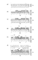
次に、このような液体吐出ヘッドの製造方法の一例を説明する。
図5(a)〜(e)は図3(a)に示す液体吐出ヘッドの製造工程を説明するための断面模式図である。
(Production method)
Next, an example of a method for manufacturing such a liquid discharge head will be described.
5A to 5E are schematic cross-sectional views for explaining a manufacturing process of the liquid discharge head shown in FIG.
トランジスタ等の駆動素子が設けられたシリコンからなる基体101の上に、基体101の一部を熱酸化して熱酸化層102を設け、さらに、スパッタ法またはCVD法を用いてSiO2等のシリコン化合物からなる蓄熱層103を設ける(図4(a))。
A part of the
次に蓄熱層103の上に、通電することで発熱する材料(例えばTaSiNやWSiNなど)からなる発熱抵抗層104を反応スパッタリング法により約50nmの厚さ設ける。さらに一対の電極層105となる、Al,Al−Si,Al−Cu等の導電材料層をスパッタリング法により約300nmの厚さに形成する。そして、フォトリソグラフィ法を用い、発熱抵抗層104および電極層105に対して同時にドライエッチング法を用いてパターニングを行う。なお、本実施形態では、ドライエッチングとしてリアクティブイオンエッチング(RIE)法を用いる。このとき隣り合うエネルギー発生素子108間で、確実に電気的に独立となるように、蓄熱層103の表面がオーバーエッチングされる程度までに、十分にドライエッチング法を用いて除去することが好ましい。
Next, a
次に、図4(b)に示すエネルギー発生素子108を形成するために、再度フォトリソグラフィ法を用いてエネルギー発生素子108に対応する部分が開口するようにレジストマスクを設け、ウエットエッチング法を用いて開口部の導電材料層を除去する。これにより、エネルギー発生素子108を構成する段差を有する一対の電極層105と発熱抵抗層104が形成される。
Next, in order to form the
次に、プラズマCVD法を用いて、図4(c)に示すように、少なくとも一対の電極層105と発熱抵抗層104の境界部の段差に対応する部分と一対の電極層105の間の発熱抵抗層104の部分の上に絶縁層106としてSiN膜を約350nmの厚みに形成する。このとき一対の電極層105と発熱抵抗層104の境界部の段差に対応する部分の絶縁層106はテーパー形状となる。
Next, using a plasma CVD method, as shown in FIG. 4C, heat generation between at least a portion corresponding to a step at the boundary between the pair of
次に、絶縁層106上にスパッタリング法により、陽極となるような電圧を印加することで電気化学反応を生じてインク中に溶出するイリジウムまたはルテニウム等の白金族の金属材料を約200nmの厚さ形成する。その後図4(d)に示す形状となるように、フォトリソグラフィ法を用いて形成したレジストマスクを用いてドライエッチングして、エネルギー発生素子108を被覆する保護層107および対向電極111のパターンとなるようにパターニングする。このとき、絶縁層106のテーパー形状に対応する保護層107のテーパー部は、膜厚が薄く、かつ、膜質が悪い状態となっている。
Next, a platinum group metal material such as iridium or ruthenium that causes an electrochemical reaction by applying a voltage to become an anode on the insulating
次に保護層107の上に、キャビテーション等の物理的衝撃や化学的衝撃に強く、かつ、電圧を印加して通電しても溶解しないタンタルまたはニオブ等を含有する金属材料で約250nmの厚さとなるようにスパッタリング法を用いて形成する。その後、図4(e)に示すような保護層107のテーパー部107aと保護層107の端部とを被覆し、かつ電極としても用いられる被覆層110となるようにドライエッチング法等を用いてパターニングする。
Next, on the
なお、コゲ除去動作を繰り返したとしても保護層107のテーパー部107aが溶出しないように、図4(e)のように被覆層110は、保護層107の膜厚と同程度の距離テーパー部107aよりも内側まで覆うようにパターニングすることが好ましい。具体的には保護層を約200nmの膜厚で設けた場合には、約200nm内側まで被覆するように被覆層110を設ける。またこの時、対向電極111の端部を約200nm覆うように被覆層110も同時にパターニングしてもよい。
In order to prevent the
次に、液体吐出ヘッド用基板100の上に図4(f)のようにエポキシ樹脂等の熱硬化性樹脂の硬化物で、液体を吐出するための吐出口113と、吐出口113に連通する流路114の面となる流路形成部材112を設ける。さらにインクを流路114に供給するために液体吐出ヘッド用基板100を貫通する供給口45を形成することで液体吐出ヘッド41が設けられる。
Next, as shown in FIG. 4F, the liquid
このような液体吐出ヘッド41を用いて、1.0×10⁷回吐出動作を行ったところ、吐出口によっては、インクがまっすぐに吐出されなかったりインク滴の量が少なくなるなど安定した吐出が行えない状態となった。このような吐出口に対応するエネルギー発生素子108の熱作用部を光学顕微鏡を用いて観察すると、コゲが付着していることが確認された。このような液体吐出ヘッド41に、電源121を用いて保護層107が陽極となるようにDC電位差10Vを30sec印加したところ、保護層107上に堆積したコゲが除去され、安定した記録動作をできるような状態に回復した。さらに、コゲの付着動作とコゲ除去動作を30回程度繰り返し行った後に液体吐出ヘッド41を分解して観察を行ったところ、テーパー部107aは被覆層110で保護されており、溶出していないことが確認された。
When such a
(第二の実施形態)
第一の実施形態においては、絶縁層106と保護層107とを直接接するように設ける構成を示したが、図6(c)に示すように絶縁層106と保護層107との間に、密着性を向上させるための密着層109を設けた構成を本実施形態において説明する。このような密着層109は、シリコン化合物からなる絶縁層106およびイリジウムやルテニウム等の白金族の金属材料からなる保護層107との密着性のよい、タンタル、クロム、チタン、ニオブ等を含む金属材料またはこれらの合金を用いて設けることが好ましい。このような密着層109を設ける以外は、第一の実施形態と同様である。
(Second embodiment)
In the first embodiment, the configuration in which the insulating
このように設けることにより、コゲ除去動作を繰り返し行っても、エネルギー発生素子108上に配置され、流路内に露出している保護層107は溶出するが、テーパー部107aは溶出しない。これによりキャビテーションによる、テーパー部を起点としたエネルギー発生素子108の破壊を防止することができる。さらに、密着層109を設けることにより、絶縁層106上の保護層107が剥離することを防止することができる。
By providing in this way, even when the kogation removing operation is repeated, the
さらに保護層107と密着層109との端部を被覆層110で被覆しておくことにより、保護層107が端部から剥離することも防止できる。
Further, by covering the end portions of the
(製造方法)
次に、このような液体吐出ヘッドの製造方法の一例を説明する。
図5(c)の絶縁層106を設ける工程までは、第一の実施形態と同様であるため省略する。
(Production method)
Next, an example of a method for manufacturing such a liquid discharge head will be described.
Since the process up to the step of providing the insulating
絶縁層106上に、タンタル、クロム、チタン、ニオブ等の金属材料またはこれらの合金を用いて密着層109となる材料層と、イリジウムやルテニウム等の白金族の金属材料を用いて保護層107となる材料層とをスパッタリング法により連続して成膜する。このとき、密着層109となる材料層は約20nm、保護層107となる材料層は約200nmの厚さとなるように連続で形成する。
On the insulating
図5(a)に示す形状となるように、フォトリソグラフィ法を用いて形成したレジストマスクを用いてドライエッチングして、エネルギー発生素子108を被覆する保護層107および対向電極111のパターンとなるようにパターニングする。このとき密着層109となる材料層も同時に同じ形状となるようにパターニングを行うことで、密着層を形成することができる。
Dry etching is performed using a resist mask formed by photolithography so that the shape shown in FIG. 5A is obtained, so that the pattern of the
次に保護層107の上に、キャビテーション等の物理的衝撃や化学的衝撃に強く、かつ、電圧を印加しても溶解しないタンタルまたはニオブ等を含む金属材料で約250nmの厚さとなるようにスパッタリング法を用いて形成する。その後、図5(b)に示すような保護層107のテーパー部107aと保護層107の端部とを被覆し、かつ電極としても用いられる被覆層110となるようにドライエッチング法等を用いてパターニングする。ここで、コゲ除去動作を繰り返したとしても保護層107のテーパー部107aが溶出しないように、図5(b)のように被覆層110は、保護層107の膜厚と同程度の距離テーパー部107aよりも内側まで覆うようにパターニングを行うことが好ましい。具体的には保護層を約200nmの膜厚で設けた場合には、約200nm内側まで被覆するように被覆層110をパターニングする。またこの時、対向電極111の端部を約200nm覆うように被覆層110も同時にパターニングしてもよい。
Next, sputtering is performed on the
次に、液体吐出ヘッド用基板100の上に図5(c)のようにエポキシ樹脂等の熱硬化性樹脂の硬化物で、液体を吐出するための吐出口113と、吐出口113に連通する流路114の面となる流路形成部材112を設ける。さらにインクを流路114に供給するために液体吐出ヘッド用基板100を貫通する供給口45を形成する。
Next, as shown in FIG. 5C, the liquid
このように製造することにより、コゲ除去動作を行うことができる液体吐出ヘッド41を設けることができる。
By manufacturing in this way, the
100 液体吐出ヘッド用基板
101 基板
104 発熱抵抗層
105 電極層
106 絶縁層
107 保護層
108 エネルギー発生素子
109 密着層
110 被覆層
111 対向電極
DESCRIPTION OF
Claims (10)
前記エネルギー発生素子に対応する位置に少なくとも設けられ、液体と電気化学反応を起こして溶出する材料からなる保護層と、
を備える液体吐出ヘッドであって、
前記保護層の表面のうちの、前記一対の電極層と前記発熱抵抗層との境界部に対応する第1の領域には被覆層が設けられており、前記保護層の前記表面のうちの、前記エネルギー発生素子に対応する第2の領域の少なくとも一部には前記被覆層が設けられていないことを特徴とする液体吐出ヘッド。 An energy generating element composed of a heating resistance layer made of a material that generates heat when energized, and a pair of electrode layers used to energize the heating resistance layer, and generates heat energy;
A protective layer made of a material that is provided at least at a position corresponding to the energy generating element and elutes by causing an electrochemical reaction with the liquid;
A liquid ejection head comprising:
A covering layer is provided in a first region corresponding to a boundary portion between the pair of electrode layers and the heating resistance layer in the surface of the protective layer, and of the surface of the protective layer, The liquid ejection head, wherein the coating layer is not provided in at least a part of the second region corresponding to the energy generating element .
前記基板の前記面に直交する方向から見て、前記被覆層の端部は前記エネルギー発生素子と重なる位置に位置している請求項1乃至請求項7のいずれか1項に記載の液体吐出ヘッド。 A substrate having a surface provided with the energy generating element;
8. The liquid ejection head according to claim 1 , wherein an end portion of the coating layer is located at a position overlapping with the energy generating element when viewed from a direction orthogonal to the surface of the substrate. .
前記保護層が前記保護層と接触する前記液体に対して陽極となるように電圧を印加する印加手段を有することを特徴とする液体吐出装置。 A liquid ejection apparatus comprising the liquid ejection head according to any one of claims 1 to 9 ,
A liquid ejecting apparatus comprising: an application unit configured to apply a voltage so that the protective layer serves as an anode for the liquid in contact with the protective layer.
Priority Applications (2)
| Application Number | Priority Date | Filing Date | Title |
|---|---|---|---|
| JP2011267153A JP5932318B2 (en) | 2011-12-06 | 2011-12-06 | Liquid discharge head and liquid discharge apparatus |
| US13/693,845 US8721050B2 (en) | 2011-12-06 | 2012-12-04 | Liquid discharge head with protective layer and liquid discharge device |
Applications Claiming Priority (1)
| Application Number | Priority Date | Filing Date | Title |
|---|---|---|---|
| JP2011267153A JP5932318B2 (en) | 2011-12-06 | 2011-12-06 | Liquid discharge head and liquid discharge apparatus |
Publications (3)
| Publication Number | Publication Date |
|---|---|
| JP2013119180A JP2013119180A (en) | 2013-06-17 |
| JP2013119180A5 JP2013119180A5 (en) | 2014-12-18 |
| JP5932318B2 true JP5932318B2 (en) | 2016-06-08 |
Family
ID=48523696
Family Applications (1)
| Application Number | Title | Priority Date | Filing Date |
|---|---|---|---|
| JP2011267153A Expired - Fee Related JP5932318B2 (en) | 2011-12-06 | 2011-12-06 | Liquid discharge head and liquid discharge apparatus |
Country Status (2)
| Country | Link |
|---|---|
| US (1) | US8721050B2 (en) |
| JP (1) | JP5932318B2 (en) |
Families Citing this family (6)
| Publication number | Priority date | Publication date | Assignee | Title |
|---|---|---|---|---|
| JP6143483B2 (en) * | 2013-02-01 | 2017-06-07 | キヤノン株式会社 | Liquid ejection apparatus and liquid ejection head cleaning method |
| CN104859029B (en) * | 2014-02-20 | 2017-11-14 | 研能科技股份有限公司 | Ceramic rapid molding device |
| JP6833410B2 (en) * | 2015-09-07 | 2021-02-24 | キヤノン株式会社 | Liquid discharge head cleaning method, liquid discharge device |
| JP2018176697A (en) * | 2017-04-21 | 2018-11-15 | キヤノン株式会社 | Method of disconnecting fuse part of liquid discharge head, and liquid discharge device |
| JP7023650B2 (en) * | 2017-09-27 | 2022-02-22 | キヤノン株式会社 | Liquid discharge head and its manufacturing method |
| JP2022146318A (en) * | 2021-03-22 | 2022-10-05 | キヤノン株式会社 | Method of manufacturing substrate for liquid discharge head |
Family Cites Families (4)
| Publication number | Priority date | Publication date | Assignee | Title |
|---|---|---|---|---|
| DE3446968A1 (en) * | 1983-12-26 | 1985-07-04 | Canon K.K., Tokio/Tokyo | LIQUID JET RECORDING HEAD |
| JPS60137663A (en) * | 1983-12-26 | 1985-07-22 | Canon Inc | Liquid jet recording head |
| JP4926669B2 (en) | 2005-12-09 | 2012-05-09 | キヤノン株式会社 | Inkjet head cleaning method, inkjet head, and inkjet recording apparatus |
| JP5328607B2 (en) * | 2008-11-17 | 2013-10-30 | キヤノン株式会社 | Substrate for liquid discharge head, liquid discharge head having the substrate, cleaning method for the head, and liquid discharge apparatus using the head |
-
2011
- 2011-12-06 JP JP2011267153A patent/JP5932318B2/en not_active Expired - Fee Related
-
2012
- 2012-12-04 US US13/693,845 patent/US8721050B2/en not_active Expired - Fee Related
Also Published As
| Publication number | Publication date |
|---|---|
| US8721050B2 (en) | 2014-05-13 |
| US20130141494A1 (en) | 2013-06-06 |
| JP2013119180A (en) | 2013-06-17 |
Similar Documents
| Publication | Publication Date | Title |
|---|---|---|
| JP5932318B2 (en) | Liquid discharge head and liquid discharge apparatus | |
| US8491087B2 (en) | Circuit board for ink jet head, ink jet head having the same, method for cleaning the head and ink jet printing apparatus using the head | |
| JP5312202B2 (en) | Liquid discharge head and manufacturing method thereof | |
| US20090244198A1 (en) | Ink jet recording head, manufacturing method thereof, and electron device | |
| US20120047737A1 (en) | Method for manufacturing substrate for liquid ejection head and method for manufacturing liquid ejection head | |
| JP5006663B2 (en) | Liquid discharge head | |
| JP4995355B2 (en) | Inkjet head and inkjet recording apparatus | |
| JP6327982B2 (en) | Cleaning method for liquid discharge head | |
| JP5921142B2 (en) | Liquid discharge head and method of manufacturing liquid discharge head | |
| JP6230290B2 (en) | Liquid discharge head substrate, liquid discharge head, and method for manufacturing liquid discharge head substrate | |
| US9179503B2 (en) | Method for manufacturing liquid ejection head | |
| KR100856412B1 (en) | Method of manufacturing inkjet printhead | |
| EP3392044B1 (en) | Method of disconnecting fuse portion of liquid-discharging head and liquid discharge apparatus | |
| JP6921698B2 (en) | Liquid discharge head and its manufacturing method | |
| CN110181945B (en) | Liquid discharge head substrate and liquid discharge head | |
| JP7191669B2 (en) | SUBSTRATE FOR LIQUID EJECTION HEAD AND MANUFACTURING METHOD THEREOF | |
| US20090141083A1 (en) | Inkjet printhead and method of manufacturing the same | |
| US10538085B2 (en) | Liquid discharge head substrate, liquid discharge head, and method for disconnecting fuse portion in liquid discharge head substrate | |
| JP7346119B2 (en) | Liquid ejection head cleaning method and liquid ejection device | |
| US9427953B2 (en) | Method of manufacturing liquid ejection head | |
| JP7071067B2 (en) | A method for manufacturing a substrate for a liquid discharge head, a liquid discharge head, and a substrate for a liquid discharge head. | |
| JP2012245675A (en) | Liquid ejection head, substrate for liquid ejection head, and method for manufacturing the same | |
| JP2019142216A (en) | Substrate of liquid ejection head and liquid ejection head | |
| JP2005081585A (en) | Inkjet recording head, its manufacturing method, and inkjet recording apparatus | |
| JP2017109389A (en) | Liquid discharge head, method for manufacturing liquid discharge head and recovery method |
Legal Events
| Date | Code | Title | Description |
|---|---|---|---|
| A521 | Request for written amendment filed |
Free format text: JAPANESE INTERMEDIATE CODE: A523 Effective date: 20141031 |
|
| A621 | Written request for application examination |
Free format text: JAPANESE INTERMEDIATE CODE: A621 Effective date: 20141031 |
|
| A977 | Report on retrieval |
Free format text: JAPANESE INTERMEDIATE CODE: A971007 Effective date: 20150824 |
|
| A131 | Notification of reasons for refusal |
Free format text: JAPANESE INTERMEDIATE CODE: A131 Effective date: 20150901 |
|
| A521 | Request for written amendment filed |
Free format text: JAPANESE INTERMEDIATE CODE: A523 Effective date: 20151102 |
|
| TRDD | Decision of grant or rejection written | ||
| A01 | Written decision to grant a patent or to grant a registration (utility model) |
Free format text: JAPANESE INTERMEDIATE CODE: A01 Effective date: 20160405 |
|
| A61 | First payment of annual fees (during grant procedure) |
Free format text: JAPANESE INTERMEDIATE CODE: A61 Effective date: 20160428 |
|
| R151 | Written notification of patent or utility model registration |
Ref document number: 5932318 Country of ref document: JP Free format text: JAPANESE INTERMEDIATE CODE: R151 |
|
| LAPS | Cancellation because of no payment of annual fees |