JP5928383B2 - Light source device and display device - Google Patents
Light source device and display device Download PDFInfo
- Publication number
- JP5928383B2 JP5928383B2 JP2013060060A JP2013060060A JP5928383B2 JP 5928383 B2 JP5928383 B2 JP 5928383B2 JP 2013060060 A JP2013060060 A JP 2013060060A JP 2013060060 A JP2013060060 A JP 2013060060A JP 5928383 B2 JP5928383 B2 JP 5928383B2
- Authority
- JP
- Japan
- Prior art keywords
- light
- light source
- wavelength
- wavelength range
- emits
- Prior art date
- Legal status (The legal status is an assumption and is not a legal conclusion. Google has not performed a legal analysis and makes no representation as to the accuracy of the status listed.)
- Active
Links
Images


Classifications
-
- G—PHYSICS
- G02—OPTICS
- G02B—OPTICAL ELEMENTS, SYSTEMS OR APPARATUS
- G02B27/00—Optical systems or apparatus not provided for by any of the groups G02B1/00 - G02B26/00, G02B30/00
- G02B27/10—Beam splitting or combining systems
- G02B27/1006—Beam splitting or combining systems for splitting or combining different wavelengths
-
- F—MECHANICAL ENGINEERING; LIGHTING; HEATING; WEAPONS; BLASTING
- F21—LIGHTING
- F21V—FUNCTIONAL FEATURES OR DETAILS OF LIGHTING DEVICES OR SYSTEMS THEREOF; STRUCTURAL COMBINATIONS OF LIGHTING DEVICES WITH OTHER ARTICLES, NOT OTHERWISE PROVIDED FOR
- F21V13/00—Producing particular characteristics or distribution of the light emitted by means of a combination of elements specified in two or more of main groups F21V1/00 - F21V11/00
- F21V13/02—Combinations of only two kinds of elements
- F21V13/08—Combinations of only two kinds of elements the elements being filters or photoluminescent elements and reflectors
-
- F—MECHANICAL ENGINEERING; LIGHTING; HEATING; WEAPONS; BLASTING
- F21—LIGHTING
- F21V—FUNCTIONAL FEATURES OR DETAILS OF LIGHTING DEVICES OR SYSTEMS THEREOF; STRUCTURAL COMBINATIONS OF LIGHTING DEVICES WITH OTHER ARTICLES, NOT OTHERWISE PROVIDED FOR
- F21V9/00—Elements for modifying spectral properties, polarisation or intensity of the light emitted, e.g. filters
- F21V9/30—Elements containing photoluminescent material distinct from or spaced from the light source
-
- G—PHYSICS
- G02—OPTICS
- G02B—OPTICAL ELEMENTS, SYSTEMS OR APPARATUS
- G02B27/00—Optical systems or apparatus not provided for by any of the groups G02B1/00 - G02B26/00, G02B30/00
- G02B27/10—Beam splitting or combining systems
- G02B27/14—Beam splitting or combining systems operating by reflection only
- G02B27/141—Beam splitting or combining systems operating by reflection only using dichroic mirrors
-
- G—PHYSICS
- G03—PHOTOGRAPHY; CINEMATOGRAPHY; ANALOGOUS TECHNIQUES USING WAVES OTHER THAN OPTICAL WAVES; ELECTROGRAPHY; HOLOGRAPHY
- G03B—APPARATUS OR ARRANGEMENTS FOR TAKING PHOTOGRAPHS OR FOR PROJECTING OR VIEWING THEM; APPARATUS OR ARRANGEMENTS EMPLOYING ANALOGOUS TECHNIQUES USING WAVES OTHER THAN OPTICAL WAVES; ACCESSORIES THEREFOR
- G03B21/00—Projectors or projection-type viewers; Accessories therefor
- G03B21/14—Details
- G03B21/20—Lamp housings
- G03B21/2006—Lamp housings characterised by the light source
- G03B21/2033—LED or laser light sources
- G03B21/204—LED or laser light sources using secondary light emission, e.g. luminescence or fluorescence
-
- G—PHYSICS
- G03—PHOTOGRAPHY; CINEMATOGRAPHY; ANALOGOUS TECHNIQUES USING WAVES OTHER THAN OPTICAL WAVES; ELECTROGRAPHY; HOLOGRAPHY
- G03B—APPARATUS OR ARRANGEMENTS FOR TAKING PHOTOGRAPHS OR FOR PROJECTING OR VIEWING THEM; APPARATUS OR ARRANGEMENTS EMPLOYING ANALOGOUS TECHNIQUES USING WAVES OTHER THAN OPTICAL WAVES; ACCESSORIES THEREFOR
- G03B33/00—Colour photography, other than mere exposure or projection of a colour film
- G03B33/06—Colour photography, other than mere exposure or projection of a colour film by additive-colour projection apparatus
-
- H—ELECTRICITY
- H04—ELECTRIC COMMUNICATION TECHNIQUE
- H04N—PICTORIAL COMMUNICATION, e.g. TELEVISION
- H04N9/00—Details of colour television systems
- H04N9/12—Picture reproducers
- H04N9/31—Projection devices for colour picture display, e.g. using electronic spatial light modulators [ESLM]
- H04N9/3141—Constructional details thereof
- H04N9/315—Modulator illumination systems
- H04N9/3158—Modulator illumination systems for controlling the spectrum
Description
本開示は、プロジェクター等の表示装置に用いられる光源装置およびこれを備える表示装置に関する。 The present disclosure relates to a light source device used in a display device such as a projector and a display device including the same.
プロジェクター用の光源としては、明るさやコストパフォーマンスの観点から超高圧水銀ランプが主として用いられているが、長寿命性、高機能付加等の観点から、長寿命であり色域の広い固体光源が注目されている。固体光源は、半導体のp/n接合による発光現象を用いた光源であり、LEDやレーザ(LD)等がある。近年では、例えば特許文献1のような、特定の波長域の光を照射すると当該光とは異なる波長域の光を発光する蛍光体材料に対して固体光源により光を照射し、蛍光発光した光を利用する光源装置がプロジェクター等に利用されている。 As a light source for projectors, ultra-high pressure mercury lamps are mainly used from the viewpoints of brightness and cost performance, but solid-state light sources with long life and wide color gamut are attracting attention from the viewpoints of long life and high functionality. Has been. The solid light source is a light source using a light emission phenomenon caused by a semiconductor p / n junction, and includes an LED, a laser (LD), and the like. In recent years, for example, as disclosed in Patent Document 1, when a light of a specific wavelength region is irradiated, a phosphor material that emits light of a wavelength region different from the light is irradiated with light by a solid light source, and the fluorescence emitted light A light source device that uses the projector is used for a projector or the like.
例えば図9に示すように、第1の光源11から出射された光を、蛍光体材料13が設けられたガラス等の透過部材14aにレンズ12を用いて集光し、透過部材14aを通過した光をレンズ15にて平行光にして出力する透過型の光源装置10Aがある。あるいは、図10に示すように、第1の光源11から出射された光を、蛍光体材料13が設けられた反射部材14dにレンズ17を用いて集光し、反射部材14dにより反射された光をダイクロイックミラー16にて反射して出力する反射型の光源装置10Bがある。
For example, as shown in FIG. 9, the light emitted from the
このような蛍光体材料を用いた光源装置は、従来プロジェクターに用いられている高圧水銀ランプに比べて長寿命というメリットがある。また、蛍光体材料を用いることで、被照射物の表面でギラギラと輝く斑点が発生するスペックルノイズを低減することも可能である。 A light source device using such a phosphor material has an advantage of a long life compared to a high-pressure mercury lamp used in a conventional projector. In addition, by using a phosphor material, it is also possible to reduce speckle noise in which bright spots occur on the surface of the irradiated object.
一方で、プロジェクター用に適切な発光スペクトルを持つ蛍光体材料がいまだ実用されていないという現状がある。 On the other hand, there is a current situation that a phosphor material having an appropriate emission spectrum for a projector has not yet been put into practical use.
プロジェクター用の光源としては、図11に示すようなDCI規格やsRGB等に基づく映像表示機器の規格色域と白色を表示できることが望ましい。このような色域を表示するためには、図12に示すように、青色波長域、緑色波長域および赤色波長域のそれぞれについて発光スペクトルを持つ光源が理想の1つである。このような発光スペクトルを有する光源は、赤、緑、青の各原色およびこれらの原色を同時に点灯したときの白において規格の近傍の色を表示することができる。 As a light source for a projector, it is desirable that the standard color gamut and white color of a video display device based on the DCI standard, sRGB, or the like as shown in FIG. 11 can be displayed. In order to display such a color gamut, as shown in FIG. 12, a light source having an emission spectrum for each of the blue wavelength range, the green wavelength range, and the red wavelength range is an ideal one. A light source having such an emission spectrum can display red, green, and blue primary colors and colors near the standard in white when these primary colors are simultaneously turned on.
このスペクトルを蛍光体で実現する方法としては、個別の発光スペクトルを持つ蛍光体を混ぜ合わせて使用する方法がある。例えば図13に示すように、青色の発光波長域を有する蛍光体A、緑色の発光波長域を有する蛍光体B、および赤色の発光波長域を有する蛍光体Cを混ぜ合わせて使用する。しかし、蛍光体の発光には輝度飽和や温度消光という現象が存在する。これは、蛍光体へ強い光を入射した場合、図14に示すように蛍光発光の効率が下がってしまうというものである。発光効率が低い状態では、効率のよい明るい光源は実現できない。 As a method of realizing this spectrum with a phosphor, there is a method of using a mixture of phosphors having individual emission spectra. For example, as shown in FIG. 13, a phosphor A having a blue emission wavelength range, a phosphor B having a green emission wavelength range, and a phosphor C having a red emission wavelength range are used in combination. However, there are phenomena such as luminance saturation and temperature quenching in the light emission of the phosphor. This is because when the strong light is incident on the phosphor, the efficiency of the fluorescence emission decreases as shown in FIG. In a state where the luminous efficiency is low, an efficient bright light source cannot be realized.
このように、高効率で色再現性のよい光源装置を実現することが求められていた。 Thus, it has been desired to realize a light source device with high efficiency and good color reproducibility.
本開示によれば、第1波長域の光を出射する第1の光源と、第1波長域と異なる第2波長域の光を出射する第2の光源と、蛍光体材料からなり、第1波長域の光が照射されて異なる波長域の蛍光発光光を出射する波長変換部と、第2波長域に対応する特定波長域に対する波長選択性を有し、入射する第1の光源からの第1波長域の光、第2の光源からの第2波長域の光、および蛍光発光光を合波する合波器と、を備える、光源装置が提供される。 According to the present disclosure, the first light source that emits light in the first wavelength region, the second light source that emits light in the second wavelength region different from the first wavelength region, and the phosphor material, A wavelength conversion unit that emits fluorescence emission light in a different wavelength range when irradiated with light in the wavelength range; and a wavelength selectivity for a specific wavelength range corresponding to the second wavelength range, and the first light source from the incident first light source There is provided a light source device including a light of one wavelength region, a light of a second wavelength region from a second light source, and a multiplexer that multiplexes the fluorescence emission light.
また、本開示によれば、第1波長域の光を出射する第1の光源と、第1波長域と異なる第2波長域の光を出射する第2の光源と、蛍光体材料からなり、第1波長域の光が照射されて異なる波長域の蛍光発光光を出射する波長変換部と、第1波長域および第2波長域に対応する特定波長域に対する波長選択性を有し、入射する第1の光源からの第1波長域の光、第2の光源からの第2波長域の光、および蛍光発光光を合波する合波器と、を備える、光源装置が提供される。 Further, according to the present disclosure, the first light source that emits light in the first wavelength range, the second light source that emits light in the second wavelength range different from the first wavelength range, and a phosphor material, A wavelength conversion unit that emits fluorescence emission light in a different wavelength range when irradiated with light in the first wavelength range, and has wavelength selectivity with respect to a specific wavelength range corresponding to the first wavelength range and the second wavelength range, and is incident There is provided a light source device comprising: a first wavelength range light from a first light source; a second wavelength range light from a second light source; and a multiplexer that combines fluorescence emission light.
さらに、本開示によれば、光源部と、入射された光を変調し合成する光変調合成系と、光源部から出射された光を光変調合成系へ導く照明光学系と、光変調合成系から出射された画像を投射する投射光学系と、からなり、光源部は、第1波長域の光を出射する第1の光源と、第1波長域と異なる第2波長域の光を出射する第2の光源と、蛍光体材料からなり、第1波長域の光が照射されて異なる波長域の蛍光発光光を出射する波長変換部と、第2波長域に対応する特定波長域に対する波長選択性を有し、入射する第1の光源からの第1波長域の光、第2の光源からの第2波長域の光、および蛍光発光光を合波する合波器と、を備える、表示装置が提供される。 Furthermore, according to the present disclosure, a light source unit, a light modulation synthesis system that modulates and combines incident light, an illumination optical system that guides light emitted from the light source unit to the light modulation synthesis system, and a light modulation synthesis system And a light source unit that emits light in a first wavelength range and light in a second wavelength range different from the first wavelength range. A wavelength conversion unit that is made of a phosphor material and emits fluorescence emission light in a different wavelength range when irradiated with light in the first wavelength range, and wavelength selection for a specific wavelength range corresponding to the second wavelength range And a combiner that combines the light in the first wavelength range from the incident first light source, the light in the second wavelength range from the second light source, and the fluorescence emission light. An apparatus is provided.
また、本開示によれば、光源部と、入射された光を変調し合成する光変調合成系と、光源部から出射された光を光変調合成系へ導く照明光学系と、光変調合成系から出射された画像を投射する投射光学系と、からなり、光源部は、第1波長域の光を出射する第1の光源と、第1波長域と異なる第2波長域の光を出射する第2の光源と、蛍光体材料からなり、第1波長域の光が照射されて異なる波長域の蛍光発光光を出射する波長変換部と、第1波長域および第2波長域に対応する特定波長域に対する波長選択性を有し、入射する第1の光源からの第1波長域の光、第2の光源からの第2波長域の光、および蛍光発光光を合波する合波器と、を備える、表示装置が提供される。 In addition, according to the present disclosure, a light source unit, a light modulation synthesis system that modulates and combines incident light, an illumination optical system that guides light emitted from the light source unit to the light modulation synthesis system, and a light modulation synthesis system And a light source unit that emits light in a first wavelength range and light in a second wavelength range different from the first wavelength range. A second light source, a wavelength conversion unit that is made of a phosphor material and emits fluorescent emission light in a different wavelength range when irradiated with light in the first wavelength range, and a specification corresponding to the first wavelength range and the second wavelength range A multiplexer having wavelength selectivity with respect to a wavelength range, and combining light of a first wavelength range from an incident first light source, light of a second wavelength range from a second light source, and fluorescence emission light; A display device is provided.
本開示によれば、波長変換部により第1波長域の光から変換された蛍光発光光および第1の光源からの第1波長域の光と、第2の光源による第2波長域の光とが合波器により合成する。合成された光は、第1波長域、第2波長域および蛍光発光光の各波長スペクトルを有するものとなる。これにより、第1の光源からの第1波長域の光と蛍光発光光との発光スペクトルで足りない第2波長域の光を第2の光源を用いて効率よく補うことができる。 According to the present disclosure, the fluorescence emission light converted from the light in the first wavelength range by the wavelength conversion unit, the light in the first wavelength range from the first light source, and the light in the second wavelength range from the second light source Is synthesized by a multiplexer. The synthesized light has the first wavelength region, the second wavelength region, and each wavelength spectrum of the fluorescence emission light. Thereby, the light of the 2nd wavelength range which is insufficient in the emission spectrum of the light of the 1st wavelength range from the 1st light source and fluorescence emitted light can be efficiently supplemented using the 2nd light source.
以上説明したように本開示によれば、高効率で色再現性のよい光源装置を実現することができる。 As described above, according to the present disclosure, a light source device with high efficiency and good color reproducibility can be realized.
以下に添付図面を参照しながら、本開示の好適な実施の形態について詳細に説明する。なお、本明細書及び図面において、実質的に同一の機能構成を有する構成要素については、同一の符号を付することにより重複説明を省略する。 Hereinafter, preferred embodiments of the present disclosure will be described in detail with reference to the accompanying drawings. In addition, in this specification and drawing, about the component which has the substantially same function structure, duplication description is abbreviate | omitted by attaching | subjecting the same code | symbol.
なお、説明は以下の順序で行うものとする。
1.第1の実施形態(2つのダイクロイックミラーを備える光源部)
1.1.表示装置の構成
1.2.光源部の構成
2.第2の実施形態(1つのダイクロイックミラーを備える光源部)
The description will be made in the following order.
1. 1st Embodiment (light source part provided with two dichroic mirrors)
1.1. Configuration of display device 1.2. 1. Configuration of light source unit Second embodiment (light source unit including one dichroic mirror)
<1.第1の実施形態>
[1.1.表示装置の構成]
まず、図1を参照して、本開示の第1の実施形態に係る光源部100を備える表示装置1の一構成例について説明する。図1は、本実施形態に係る光源部100を備える表示装置1の一構成例を示す概略構成図である。
<1. First Embodiment>
[1.1. Configuration of display device]
First, a configuration example of the display device 1 including the
本実施形態に係る表示装置1は、光を発する光源からの光を集め、画像を表示させるデバイスを通して投影レンズから光を出射し、スクリーンS等の表示面に画像を投影するプロジェクターの一構成例を示している。図1に示す表示装置1は、マイクロディスプレイとして3LCDを用いたプロジェクターの一構成例である。 The display device 1 according to the present embodiment collects light from a light source that emits light, emits light from a projection lens through a device that displays an image, and projects an image on a display surface such as a screen S. Is shown. A display device 1 shown in FIG. 1 is a configuration example of a projector using a 3LCD as a micro display.
光源部100から出射された光は、表示画像の端部まで明るさを維持するように第1レンズアレイ2aおよび第2レンズアレイ2bからなるインテグレータレンズ2を通過した後、偏光変換素子3a、集光レンズ3bを通過し、波長域毎に分離される。
The light emitted from the
集光レンズ3bを通過した光は、赤色の波長域の光のみを反射し、その他の波長域の光を通過させる第1反射ダイクロイックミラー4aに入射する。これにより、赤色の波長域の光は第1反射ダイクロイックミラー4aにより反射されて反射ミラー5a側へ進行する。赤色の波長域の光は、反射ミラー5aによりさらに反射されて赤色用液晶パネル6aに入射する。
The light that has passed through the
第1反射ダイクロイックミラー4aを通過したその他の波長域の光は第2反射ダイクロイックミラー4bへ入射する。第2反射ダイクロイックミラー4bは、緑色の波長域の光のみを反射し、その他の波長域の光、すなわち青色の波長域の光を通過させる。第2反射ダイクロイックミラー4bにより反射された緑色の波長域の光は緑色用液晶パネル6bに入射する。また、第2反射ダイクロイックミラー4bを通過した青色の波長域の光は、反射ミラー5b、5cにより反射された後、青色用液晶パネル6cへ入射する。
Light in other wavelength regions that has passed through the first reflective
各色用の液晶パネル6a〜6cは、入力画像信号に応じてそれぞれに入射した光を変調し、RGBに対応する画像の信号光を生成する。液晶パネル6a〜6cには、例えば高温ポリシリコンTFTを用いた透過型液晶素子を使用してもよい。各液晶パネル6a〜6cにより変調された信号光は、ダイクロイックプリズム7に入射され、合成される。ダイクロイックプリズム7は、赤色の信号光および青色の信号光を反射し、緑色の信号光を透過させるように、4つの三角柱を組み合わせた直方体に形成されている。ダイクロイックプリズム7により合成された各色の信号光は投射レンズ8へ入射されて、スクリーンS等の表示面に画像として投影される。
The
表示装置1において、液晶パネル6a〜6cおよびダイクロイックプリズム7は入射された光を変調して合成する光変調合成系として機能するものである。また、インテグレータレンズ2、偏光変換素子3a、集光レンズ3b、反射ダイクロイックミラー4a、4b、反射ミラー5a〜5cは、光変調合成系を構成する液晶パネル6a〜6cに光源部100からの光を導く照明光学系として機能するものである。そして、および投射レンズ8は、ダイクロイックプリズム7から出射された画像を投射する投射光学系として機能するものである。
In the display device 1, the
[1.2.光源部の構成]
このような表示装置1の光源部100として、本技術では蛍光体材料に対して固体光源から光を照射し、蛍光発光した光を利用する光源装置を用いる。しかし、蛍光体材料は、発光効率に関して、耐熱性と耐光性とに関して良好なものが少なく、輝度飽和や温度消光により蛍光発光効率が低下するものもある。例えば図13に示した原色の発光スペクトルを有するSCASN系やCASN系の蛍光体材料では、輝度飽和や温度消光が早く発生するため明るい光源を実現することができない。すなわち、蛍光体材料にレーザ等により光を強く照射すると蛍光発光効率が低下してしまい、光の照射量を少なくすると蛍光発光光量が少なく、光源部100から出射される光が暗くなってしまう。
[1.2. Configuration of light source section]
As the
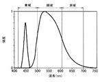
輝度飽和や温度消光が起こりにくく、明るく光源を実現できる蛍光体材料としてはYAG系の蛍光体材料がある。YAG系の蛍光体材料の代表的な発光スペクトルを図2に示す。YAG系の蛍光体材料の照射光(励起光)には通常青色系の光が使用され、青色系の光とYAG系の蛍光体材料の蛍光発光光とを光源として利用できる。すなわち、図2の青色波長域の発光スペクトル(実線)は照射光の発光スペクトルであり、緑色波長域の発光スペクトル(一点鎖線)はYAG系の蛍光体材料の蛍光発光光による発光スペクトルである。図2に示す発光スペクトルを図12に示した理想の発光スペクトルと比較すると、赤色の波長域の光が弱く、3原色のバランスが悪い。したがって、このまま白色を表示しようとすると、かなり水色に近い白色となってしまう。 As a phosphor material that is less susceptible to luminance saturation and temperature quenching and can realize a bright light source, there is a YAG-based phosphor material. A typical emission spectrum of a YAG-based phosphor material is shown in FIG. Usually, blue light is used as the irradiation light (excitation light) of the YAG phosphor material, and blue light and fluorescent light emitted from the YAG phosphor material can be used as light sources. That is, the emission spectrum in the blue wavelength range (solid line) in FIG. 2 is the emission spectrum of the irradiation light, and the emission spectrum in the green wavelength range (one-dot chain line) is the emission spectrum of the fluorescent emission light of the YAG phosphor material. When the emission spectrum shown in FIG. 2 is compared with the ideal emission spectrum shown in FIG. 12, the light in the red wavelength region is weak and the balance of the three primary colors is poor. Therefore, if the white color is displayed as it is, the white color is very close to light blue.
そこで、本実施形態に係る光源部100では、蛍光体材料の発光スペクトルで不足する色の波長域の光を効率よく補う構成とすることで、図12に示した理想の発光スペクトルに近づける。図3に、本実施形態に係る光源部100の構成を示す。図3に示す光源部100は、反射型の蛍光体材料を用いた光源装置である。
Therefore, the
図3に示すように、本実施形態に係る光源部100は、光源として、第1の光源112と、第2の光源114とを備える。第1の光源112は、蛍光体材料に対する照射用(励起用)の光源であり、例えばレーザを用いてもよい。第1の光源112は波長変換部である蛍光体材料を効率よく発光させるためのものであり、本実施形態では青色波長域(約420〜500nm)のレーザを使用している。第2の光源114は、第1の光源112と蛍光体材料による蛍光発光光とで不足する色の波長域の光を出射する。本実施形態では、第1の光源112に青色波長域のレーザを使用し、蛍光体材料としてYAG系の蛍光体材料を用いることから、図2に示したような波長スペクトルの光が得られる。赤色波長域(約610〜700nm)の光が弱いため、本実施形態に係る第2の光源114は例えば図4に示すような赤色波長域の光を出射するレーザとする。
As illustrated in FIG. 3, the
第1の光源112から出射された光は、光源部100を構成する第1のダイクロイックミラー120と、レンズ130と、回転ホイール部150に設けられた蛍光体材料140とにより、2つの波長域の光とされる。レンズ130は第1の光源112と同一光路上に配置され、第1の光源112とレンズ130との間に第1のダイクロイックミラー120が配置される。第1のダイクロイックミラー120は、例えば第1の光源112とレンズ130との間の光路に対して約45°の傾斜を有して設けられる。また、レンズ130による集光が蛍光体材料140上に行われるように蛍光体材料140は配置される。このとき、後述するようにホイール152の冷却性能を高めるために、レンズ130による集光はホイール152の中心付近よりも周縁部近くに行われるのがよい。
The light emitted from the first
第1の光源112から出射された光は、第1のダイクロイックミラー120の第1面120aに入射する。第1のダイクロイックミラー120は、第1面120aから入射する第1の光源112の光を透過させる。また、第1のダイクロイックミラー120は、当該第1のダイクロイックミラー120およびレンズ130を介して第1の光源112と対向して配置された蛍光体材料140による蛍光発光光および第1の光源112の反射光を第2面120bで反射する。第1の光源112から出射された光は第1のダイクロイックミラー120を通過して、レンズ130により集光されて蛍光体材料140に照射される。
The light emitted from the first
蛍光体材料140は、YAG系の蛍光体材料であり、第1の光源112より青色波長域の光が照射されると、当該光を吸収し、青色波長域と異なる波長域の光を発光する。蛍光体材料140は、図3に示すように、例えばアルミニウム等の金属からなる円板状のホイール152に塗布されている。蛍光体材料140は全面に塗布されていてもよく、周縁部にのみ塗布されていてもよい。
The
ホイール152はその中心に設けられた回転軸154を回転中心としてモータ等の駆動部156により回転される回転ホイール部150を構成している。これは、光の照射によりホイール152が熱を持ち蛍光体材料140の発光効率が低下するのを防止するとともに、ホイール152と蛍光体材料140との接着に用いられる樹脂が溶けてしまうのを防止するための機構である。回転ホイール部150によりホイール152を回転させ、蛍光体材料140を回転させることで、ホイール152の冷却性能を上げ、蛍光体材料140の発光効率を向上させることができる。
The
蛍光体材料140により発せられる蛍光発光光は、例えば緑色波長域の光であり、蛍光体材料140により吸収されずにホイール152により反射された青色波長域の光とともにレンズ130を通過して第1のダイクロイックミラー120の第2面120bへ入射される。その際、ホイール152の表面での青色波長域の光の反射の際に、偏光を回転させるもしくは乱す機能を設けておくことにより効率よく第1のダイクロイックミラー120で反射することができる。第1のダイクロイックミラー120は第2面120bに入射した蛍光発光光および反射光を、第2のダイクロイックミラー180側へ反射する。
The fluorescent emission light emitted by the
一方、第2の光源114から出射された光は、光源部100を構成する拡散レンズ160と、レンズ170とを介して、第2のダイクロイックミラー180に入射する。拡散レンズ160、レンズ170は第2の光源114と同一光路上に順に配置され、その延長線上に第2のダイクロイックミラー180が配置される。第2のダイクロイックミラー180は、第1のダイクロイックミラー120による反射光も入射されるため、この反射光の入射方向と第2の光源114、拡散レンズ160およびレンズ170の光路とが交差する位置に設けられる。このとき第2のダイクロイックミラー180は、例えば第1のダイクロイックミラー120と略平行に、第2の光源114、拡散レンズ160およびレンズ170の光路に対して約45°の傾斜を有して設けられる。
On the other hand, the light emitted from the second
第2のダイクロイックミラー180は、第1面180aから入射する第1のダイクロイックミラー120により反射された蛍光発光光および反射光を通過させ、第2面180bから入射する第2の光源114の光を反射する。すなわち、第2のダイクロイックミラー180は、合成する特定波長域の光は反射し、その他の波長域の光は透過する特性を有するフィルタとして機能する。第2のダイクロイックミラー180は、例えば図5に示すようなノッチフィルタの特性を有するように構成される。これにより、第2面180bから入射する図4に示すような第2の光源114の波長域の光のみを反射する。
The second
第2のダイクロイックミラー180は、補強用の第2の光源114の波長域に対応する部分に絞って光を反射するように構成する。第2のダイクロイックミラー180のフィルタをかける波長域を狭めることで、第1のダイクロイックミラー120から入射される光のうち蛍光体材料140による蛍光発光光に含まれる赤色波長域の光がなるべく反射されないようにする。本実施形態において赤色波長域の光を補強する第2の光源114は、一般に出力が弱く、第2の光源114からの補強のみでは十分ではないこともある。したがって、蛍光発光光に含まれる赤色波長域の光を有効に活用するため、第2のダイクロイックミラー180をノッチフィルタ等の狭帯域フィルタとして構成している。
The second
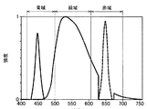
こうして第2のダイクロイックミラー180は、蛍光発光光および反射光からなる第1の光源112による出射光線上に、第2の光源114による赤色波長域の光を合成する。その結果、最終的に構成された光は、例えば図6に示すような波長スペクトルを有するものとなる。図6の赤色波長域の発光スペクトル(破線)は、第2の光源114の光によるものである。このように、本実施形態にかかる光源部100は、第1の光源112と蛍光体材料140による蛍光発光光との発光スペクトルで足りない赤色波長域の光を第2の光源114を用いて効率よく補うことができる。
In this way, the second
また、本実施形態に係る光源部100のように、補強用の第2の光源114にレーザを用いることで、発光スペクトルの幅を狭くすることで、蛍光発光光の赤色波長域の光をなるべくカットせず、カットされた赤色波長域の光を第2の光源114により補強できる。
Further, as in the
<2.第2の実施形態>
次に、図7および図8に基づいて、本開示の第2の実施形態に係る光源部200の一構成例について説明する。図7は、本実施形態に係る光源部200の一構成例を示す概略構成図である。図8は、本実施形態に係るダイクロイックミラー220の特性の一例を示す説明図である。なお、図7において、第1の実施形態に係る光源部100の構成要素と同一のものについては同一の符号を付し、詳細な説明は省略する。
<2. Second Embodiment>
Next, a configuration example of the
本実施形態に係る光源部200は、第1の実施形態のように、例えば図1に示すような表示装置1の光源部として設けられる。光源部200は、第1の実施形態に係る光源部100と比較して、蛍光体材料による蛍光発光光を反射する第1のダイクロイックミラー120に合成用フィルタとして機能する第2のダイクロイックミラー180の特性を持たせ1つの部材とした点で相違する。これにより、構成部品点数を少なくすることができ、光源部200、さらには表示装置1の小型化とコスト低減をすることができる。
The
光源部200は、図7に示すように、光源として、第1の実施形態に係る光源部100と同様、第1の光源112と、第2の光源114とを備える。第1の光源112は、蛍光体材料に対する照射用(励起用)の光源であり、例えばレーザを用いてもよい。第1の光源112は蛍光体材料を効率よく発光させるためのものであり、本実施形態においても青色波長域のレーザを使用している。第2の光源114は、第1の光源112と蛍光体材料による蛍光発光光とで不足する色の波長域の光を出射する。本実施形態でも、第1の実施形態と同様、第1の光源112に青色波長域のレーザを使用し、蛍光体材料としてYAG系の蛍光体材料を用いることから、赤色波長域の光が弱くなる。このため、本実施形態に係る第2の光源114も、例えば図4に示すような赤色波長域の光を出射するレーザとする。
As illustrated in FIG. 7, the
第1の光源112から出射された光は、光源部200を構成するダイクロイックミラー220と、レンズ130と、回転ホイール部150に設けられた蛍光体材料140とにより、2つの波長域の光とされる。レンズ130は第1の光源112と同一光路上に配置され、第1の光源112とレンズ130との間にダイクロイックミラー220が配置される。また、レンズ130による集光が蛍光体材料140上に行われるように蛍光体材料140は配置される。このとき、第1の実施形態と同様、ホイール152の冷却性能を高めるために、レンズ130による集光はホイール152の中心付近よりも周縁部近くに行われるのがよい。
The light emitted from the first
また、ダイクロイックミラー220には第2の光源114からの光も入射されるため、ダイクロイックミラー220は、この入射光の入射方向と第1の光源112およびレンズ130の間の光路とが交差する位置に設けられる。ダイクロイックミラー220は、例えば第1の光源112とレンズ130との間の光路および第2の光源114の入射方向に対して約45°の傾斜を有して設けられる。
Further, since the light from the second
ダイクロイックミラー220は、第1面220aから入射した第1の光源112の光を通過させる。さらに、ダイクロイックミラー220は、第1面220aに入射する第2の光源114も通過させる。また、ダイクロイックミラー220は、当該ダイクロイックミラー220およびレンズ130を介して第1の光源112と対向して配置された蛍光体材料140による蛍光発光光および第1の光源112の反射光を第2面220bで反射する。すなわち、ダイクロイックミラー220は、図8に示すように、青色波長域および赤色波長域の光を通過させ、緑色波長域等のその他の波長域の光は通過させない特性を有するように構成されている。
The
第1の光源112から出射された光はダイクロイックミラー220を通過して、レンズ130により集光されて蛍光体材料140に照射される。蛍光体材料140は、YAG系の蛍光体材料であり、第1の光源112より青色波長域の光が照射されると、当該光を吸収し、青色波長域と異なる波長域の光を発光する。蛍光体材料140は、冷却性能を上げ、発光効率を向上させるために回転ホイール部150のホイール152に設けて回転させてもよい。
The light emitted from the first
蛍光体材料140により発せられる蛍光発光光は、例えば緑色波長域の光であり、蛍光体材料140により吸収されずにホイール152により反射された青色波長域の光とともにレンズ130を通過してダイクロイックミラー220の第2面220bへ入射される。ダイクロイックミラー220は第2面220bに入射した蛍光発光光および反射光を、光源部200の光の出射方向へ反射する。
The fluorescent emission light emitted by the
一方、第2の光源114は、第1の光源112に対して各光の出射方向が略直交するように配置される。第2の光源114から出射した光はダイクロイックミラー220の第1面220aに入射する。ダイクロイックミラー220の第1面220aは、第2の光源114の波長域の光も通過させる。したがって、第2の光源114の光はダイクロイックミラー220を通過して、そのまま光源部200の光の出射方向へ進む。
On the other hand, the second
このように、ダイクロイックミラー220は、蛍光発光光および反射光からなる第1の光源112による出射光線上に、第2の光源114による赤色波長域の光を合成する。その結果、最終的に構成された光は、例えば図6に示したような波長スペクトルを有するものとなる。このような光源部200の構成により、第1の光源112と蛍光体材料140による蛍光発光光との発光スペクトルで足りない波長域を第2の光源114を用いて効率よく補うことができる。
In this way, the
以上、添付図面を参照しながら本開示の好適な実施形態について詳細に説明したが、本開示の技術的範囲はかかる例に限定されない。本開示の技術分野における通常の知識を有する者であれば、特許請求の範囲に記載された技術的思想の範疇内において、各種の変更例または修正例に想到し得ることは明らかであり、これらについても、当然に本開示の技術的範囲に属するものと了解される。 The preferred embodiments of the present disclosure have been described in detail above with reference to the accompanying drawings, but the technical scope of the present disclosure is not limited to such examples. It is obvious that a person having ordinary knowledge in the technical field of the present disclosure can come up with various changes or modifications within the scope of the technical idea described in the claims. Of course, it is understood that it belongs to the technical scope of the present disclosure.
例えば、上記実施形態では、光源部100、200を適用する表示装置1として図1に示すような3LCD方式のプロジェクターを例示したが、本技術はかかる例に限定されない。光源部100、200を適用する表示装置1の方式は特に限定されず、例えば、DLP方式やLCOS方式等の表示装置に適用してもよい。
For example, in the above-described embodiment, the 3LCD projector as illustrated in FIG. 1 is illustrated as the display device 1 to which the
また、上記実施形態では、第1の光源112は、特定波長域(上記実施形態では青色波長域)の光および蛍光体材料への照射用光を得るための光源であったが、本技術はかかる例に限定されない。例えば、特定波長域の光と蛍光体材料への照射用光とを別の光源により得るようにしてもよい。この場合、例えば、図3に示す光源部100の構成において、第1の光源112を蛍光体材料への照射用光として利用する。そして、青色波長域の光を得るための青色波長域用光源を、別途、第1の光源112の光の入射方向が略直交し、第1のダイクロイックミラー120の第1面120aに入射するように設ける。すなわち、青色波長域用光源は、光軸が光源部110の光の出射方向と同軸となるように設けられる。このように構成することで、上記実施形態と同様の効果を得ることができる。
Moreover, in the said embodiment, although the 1st
さらに、上記実施形態では、第1の光源112および第2の光源114はレーザを用いたが、本技術はかかる例に限定されず、例えばLED等の固体光源であればよい。レーザは、直進性を有することから本技術の光源部100、200への利用に適している。
Furthermore, in the said embodiment, although the 1st
また、図3、図7に示した上記実施形態の光源部100、200の構成に、本技術は限定されない。各光学系の配置は適宜変更可能であり、それに応じて各光学系の特性を変化させてもよい。例えば、上記第1の実施形態にて第2のダイクロイックミラー180は、合成する特定波長域(赤色波長域)の光を反射し、その他の波長域の光は透過する特性を有した。この際、第2の光源114の光の入射方向や出射方向等に応じて、合成する特定波長域(赤色波長域)の光を透過し、その他の波長域の光は反射する特性を有するようにしてもよい。なお、光源部100、200の配置に関しては、光源部100、200の光の出射方向に青色波長域、緑色波長域、赤色波長域の各光が同一軸上に重畳された後、出射されるように構成するのがよい。
Further, the present technology is not limited to the configuration of the
さらに、上記実施形態では、光源部100、200の赤色波長域の光を発する第2の光源114は光源部100、200の基台にそのまま設けることを想定して説明したが、本技術はかかる例に限定されない。赤色波長域の光を発するレーザの波長は波長域が使用温度等に応じて変化しやすい。このため、例えば第1の実施形態に係る第2のダイクロイックミラー180を赤色波長域の光を反射する狭帯域フィルタとして構成した際に、第2の光源114の波長域がずれて第2のダイクロイックミラー180で反射される波長域とのずれが生じる可能性がある。そうすると、第2の光源114の波長域の光が適切に補強されず、色域のバランスが悪化してしまう。
Furthermore, in the above-described embodiment, the second
そこで、例えば第2の光源114をペルチェ素子等により構成される温度保持機構を介して基台に設けて、第2の光源114の使用温度を一定に保持して当該光源114の光の波長域を一定にしてもよい。これにより、使用環境によらず、第2の光源114の光の波長域のばらつきを低減することができる。また、第2のダイクロイックミラー180の製造ばらつきにより反射する波長域が第2の光源114の光の波長域とずれが生じている場合にも、第2の光源114の光の波長域を第2のダイクロイックミラー180の特性に合わせ込むこともできる。
Therefore, for example, the second
なお、以下のような構成も本開示の技術的範囲に属する。
(1)第1波長域の光を出射する第1の光源と、
前記第1波長域と異なる第2波長域の光を出射する第2の光源と、
蛍光体材料からなり、前記第1波長域の光が照射されて異なる波長域の蛍光発光光を出射する波長変換部と、
前記第2波長域に対応する特定波長域に対する波長選択性を有し、入射する前記第1の光源からの前記第1波長域の光、前記第2の光源からの前記第2波長域の光、および前記蛍光発光光を合波する合波器と、
を備える、光源装置。
(2)前記第1波長域の光、前記第2波長域の光、および前記蛍光発光光は同軸上で合成される、前記(1)に記載の光源装置。
(3)前記波長変換部は、前記第1の光源の光の入射方向に対して交差する平面上を回動可能に設けられる、前記(1)または(2)に記載の光源装置。
(4)前記第1波長域は、青色波長域である、前記(1)〜(3)のいずれか1項に記載の光源装置。
(5)前記第2波長域は、赤色波長域である、前記(1)〜(4)のいずれか1項に記載の光源装置。
(6)前記第1の光源または第2の光源の少なくともいずれか一方はレーザダイオードである、前記(1)〜(5)のいずれか1項に記載の光源装置。
(7)前記第1の光源と前記波長変換部との間に、前記第1波長域の光を通過させ、前記蛍光発光光を前記合波器側へ反射する蛍光反射器をさらに備える、前記(1)〜(6)のいずれか1項に記載の光源装置。
(8)第1波長域の光を出射する第1の光源と、
前記第1波長域と異なる第2波長域の光を出射する第2の光源と、
蛍光体材料からなり、前記第1波長域の光が照射されて異なる波長域の蛍光発光光を出射する波長変換部と、
前記第1波長域および前記第2波長域に対応する特定波長域に対する波長選択性を有し、入射する前記第1の光源からの前記第1波長域の光、前記第2の光源からの前記第2波長域の光、および前記蛍光発光光を合波する合波器と、
を備える、光源装置。
(9)光源部と、
入射された光を変調し合成する光変調合成系と、
前記光源部から出射された光を前記光変調合成系へ導く照明光学系と、
前記光変調合成系から出射された画像を投射する投射光学系と、
からなり、
前記光源部は、
第1波長域の光を出射する第1の光源と、
前記第1波長域と異なる第2波長域の光を出射する第2の光源と、
蛍光体材料からなり、前記第1波長域の光が照射されて異なる波長域の蛍光発光光を出射する波長変換部と、
前記第2波長域に対応する特定波長域に対する波長選択性を有し、入射する前記第1の光源からの前記第1波長域の光、前記第2の光源からの前記第2波長域の光、および前記蛍光発光光を合波する合波器と、
を備える、表示装置。
(10)光源部と、
入射された光を変調し合成する光変調合成系と、
前記光源部から出射された光を前記光変調合成系へ導く照明光学系と、
前記光変調合成系から出射された画像を投射する投射光学系と、
からなり、
前記光源部は、
第1波長域の光を出射する第1の光源と、
前記第1波長域と異なる第2波長域の光を出射する第2の光源と、
蛍光体材料からなり、前記第1波長域の光が照射されて異なる波長域の蛍光発光光を出射する波長変換部と、
前記第1波長域および前記第2波長域に対応する特定波長域に対する波長選択性を有し、入射する前記第1の光源からの前記第1波長域の光、前記第2の光源からの前記第2波長域の光、および前記蛍光発光光を合波する合波器と、
を備える、表示装置。
The following configurations also belong to the technical scope of the present disclosure.
(1) a first light source that emits light in a first wavelength range;
A second light source that emits light in a second wavelength range different from the first wavelength range;
A wavelength conversion unit made of a phosphor material, which emits fluorescent emission light in a different wavelength range when irradiated with light in the first wavelength range; and
Light having a wavelength selectivity with respect to a specific wavelength range corresponding to the second wavelength range, and incident light in the first wavelength range from the first light source and light in the second wavelength range from the second light source. And a multiplexer for multiplexing the fluorescent emission light,
A light source device.
(2) The light source device according to (1), wherein the light in the first wavelength range, the light in the second wavelength range, and the fluorescent emission light are synthesized on the same axis.
(3) The light source device according to (1) or (2), wherein the wavelength conversion unit is rotatably provided on a plane that intersects with the light incident direction of the first light source.
(4) The light source device according to any one of (1) to (3), wherein the first wavelength range is a blue wavelength range.
(5) The light source device according to any one of (1) to (4), wherein the second wavelength range is a red wavelength range.
(6) The light source device according to any one of (1) to (5), wherein at least one of the first light source and the second light source is a laser diode.
(7) The apparatus further includes a fluorescent reflector that transmits the light in the first wavelength region and reflects the fluorescent light emission to the multiplexer side between the first light source and the wavelength converter. The light source device according to any one of (1) to (6).
(8) a first light source that emits light in a first wavelength range;
A second light source that emits light in a second wavelength range different from the first wavelength range;
A wavelength conversion unit made of a phosphor material, which emits fluorescent emission light in a different wavelength range when irradiated with light in the first wavelength range; and
It has wavelength selectivity with respect to a specific wavelength range corresponding to the first wavelength range and the second wavelength range, and the light in the first wavelength range from the incident first light source, the light from the second light source A multiplexer that multiplexes the light in the second wavelength region and the fluorescent emission light;
A light source device.
(9) a light source unit;
A light modulation and synthesis system for modulating and synthesizing incident light; and
An illumination optical system for guiding the light emitted from the light source unit to the light modulation and synthesis system;
A projection optical system for projecting an image emitted from the light modulation and synthesis system;
Consists of
The light source unit is
A first light source that emits light in a first wavelength range;
A second light source that emits light in a second wavelength range different from the first wavelength range;
A wavelength conversion unit made of a phosphor material, which emits fluorescent emission light in a different wavelength range when irradiated with light in the first wavelength range; and
Light having a wavelength selectivity with respect to a specific wavelength range corresponding to the second wavelength range, and incident light in the first wavelength range from the first light source and light in the second wavelength range from the second light source. And a multiplexer for multiplexing the fluorescent emission light,
A display device comprising:
(10) a light source unit;
A light modulation and synthesis system for modulating and synthesizing incident light; and
An illumination optical system for guiding the light emitted from the light source unit to the light modulation and synthesis system;
A projection optical system for projecting an image emitted from the light modulation and synthesis system;
Consists of
The light source unit is
A first light source that emits light in a first wavelength range;
A second light source that emits light in a second wavelength range different from the first wavelength range;
A wavelength conversion unit made of a phosphor material, which emits fluorescent emission light in a different wavelength range when irradiated with light in the first wavelength range; and
It has wavelength selectivity with respect to a specific wavelength range corresponding to the first wavelength range and the second wavelength range, and the light in the first wavelength range from the incident first light source, the light from the second light source A multiplexer that multiplexes the light in the second wavelength region and the fluorescent emission light;
A display device comprising:
1 表示装置
2 インテグレータレンズ
3a 偏光変換素子
3b 集光レンズ
4a 第1反射ダイクロイックミラー
4b 第2反射ダイクロイックミラー
5a、5b、5c 反射ミラー
6a、6b、6c 液晶パネル
7 ダイクロイックプリズム
8 投射レンズ
100 発光部
112 第1の光源
114 第2の光源
120 第1のダイクロイックミラー
130、170 レンズ
140 蛍光体材料
150 回転ホイール部
160 拡散レンズ
180 第2のダイクロイックミラー
DESCRIPTION OF SYMBOLS 1 Display apparatus 2
Claims (9)
赤色である第2波長域の光を出射する第2の光源と、
蛍光体材料からなり、照射された前記第1波長域の光の一部を異なる波長域の蛍光発光光に変換して出射する波長変換部と、
前記第2波長域に対応する特定波長域に対する波長選択性を有し、かつ、前記蛍光発光光のうち前記第2の光源が発光する波長に対応する第2波長域の一部をフィルタリングする特性を有し、入射する前記第1の光源からの前記第1波長域の光、前記第2の光源からの前記第2波長域の光、およびフィルタリングされた前記蛍光発光光を合波するダイクロイックミラーである合波器と、
を備え、
前記第2の光源からの前記第2波長域の光は、フィルタリングされた前記蛍光発光光を、フィルタリングされた波長帯域において補強する、光源装置。 A first light source that emits light in a first wavelength range that is blue ;
A second light source that emits light in a second wavelength range that is red ;
A wavelength conversion unit that is made of a phosphor material, converts a part of the irradiated light in the first wavelength range to fluorescent emission light in a different wavelength range, and emits the converted light.
A characteristic of filtering a part of the second wavelength range corresponding to the wavelength emitted by the second light source of the fluorescent light, having wavelength selectivity with respect to a specific wavelength range corresponding to the second wavelength range. has the first wavelength range of the light from the first light source incident, the dichroic mirror wherein from the second light source a second wavelength band of light, and filtered the fluorescence light multiplexes A combiner,
With
The light of the second wavelength band from the second light source, the fluorescence emission light filtered to reinforce the filtered wavelength range, the light source device.
赤色である第2波長域の光を出射する第2の光源と、
蛍光体材料からなり、照射された前記第1波長域の光の一部を異なる波長域の蛍光発光光に変換して出射する波長変換部と、
前記第1波長域および前記第2波長域に対応する特定波長域に対する波長選択性を有し、かつ、前記蛍光発光光のうち前記第2の光源が発光する波長に対応する第2波長域の一部をフィルタリングする特性を有し、入射する前記第1の光源からの前記第1波長域の光、前記第2の光源からの前記第2波長域の光、およびフィルタリングされた前記蛍光発光光を合波するダイクロイックミラーである合波器と、
を備え、
前記第2の光源からの前記第2波長域の光は、フィルタリングされた前記蛍光発光光を、フィルタリングされた波長帯域において補強する、光源装置。 A first light source that emits light in a first wavelength range that is blue ;
A second light source that emits light in a second wavelength range that is red ;
A wavelength conversion unit that is made of a phosphor material, converts a part of the irradiated light in the first wavelength range to fluorescent emission light in a different wavelength range, and emits the converted light.
A second wavelength region corresponding to a wavelength emitted by the second light source of the fluorescent emission light , and having wavelength selectivity with respect to a specific wavelength region corresponding to the first wavelength region and the second wavelength region; The first wavelength light from the incident first light source, the second wavelength light from the second light source, and the filtered fluorescence emission light having a characteristic of filtering a part A multiplexer, which is a dichroic mirror that combines
With
The light of the second wavelength band from the second light source, the fluorescence emission light filtered to reinforce the filtered wavelength range, the light source device.
入射された光を変調し合成する光変調合成系と、
前記光源部から出射された光を前記光変調合成系へ導く照明光学系と、
前記光変調合成系から出射された画像を投射する投射光学系と、
からなり、
前記光源部は、
青色である第1波長域の光を出射する第1の光源と、
赤色である第2波長域の光を出射する第2の光源と、
蛍光体材料からなり、照射された前記第1波長域の光の一部を異なる波長域の蛍光発光光に変換して出射する波長変換部と、
前記第2波長域に対応する特定波長域に対する波長選択性を有し、かつ、前記蛍光発光光のうち前記第2の光源が発光する波長に対応する第2波長域の一部をフィルタリングする特性を有し、入射する前記第1の光源からの前記第1波長域の光、前記第2の光源からの前記第2波長域の光、およびフィルタリングされた前記蛍光発光光を合波するダイクロイックミラーである合波器と、
を備え、
前記第2の光源からの前記第2波長域の光は、フィルタリングされた前記蛍光発光光を、フィルタリングされた波長帯域において補強する、表示装置。 A light source unit;
A light modulation and synthesis system for modulating and synthesizing incident light; and
An illumination optical system for guiding the light emitted from the light source unit to the light modulation and synthesis system;
A projection optical system for projecting an image emitted from the light modulation and synthesis system;
Consists of
The light source unit is
A first light source that emits light in a first wavelength range that is blue ;
A second light source that emits light in a second wavelength range that is red ;
A wavelength conversion unit that is made of a phosphor material, converts a part of the irradiated light in the first wavelength range to fluorescent emission light in a different wavelength range, and emits the converted light.
A characteristic of filtering a part of the second wavelength range corresponding to the wavelength emitted by the second light source of the fluorescent light, having wavelength selectivity with respect to a specific wavelength range corresponding to the second wavelength range. has the first wavelength range of the light from the first light source incident, the dichroic mirror wherein from the second light source a second wavelength band of light, and filtered the fluorescence light multiplexes A combiner,
With
The light of the second wavelength band from the second light source, the fluorescence emission light filtered to reinforce the filtered wavelength range, the display device.
入射された光を変調し合成する光変調合成系と、
前記光源部から出射された光を前記光変調合成系へ導く照明光学系と、
前記光変調合成系から出射された画像を投射する投射光学系と、
からなり、
前記光源部は、
青色である第1波長域の光を出射する第1の光源と、
赤色である前記第1波長域と異なる第2波長域の光を出射する第2の光源と、
蛍光体材料からなり、照射された前記第1波長域の光の一部を異なる波長域の蛍光発光光に変換して出射する波長変換部と、
前記第1波長域および前記第2波長域に対応する特定波長域に対する波長選択性を有し、かつ、前記蛍光発光光のうち前記第2の光源が発光する波長に対応する第2波長域の一部をフィルタリングする特性を有し、入射する前記第1の光源からの前記第1波長域の光、前記第2の光源からの前記第2波長域の光、およびフィルタリングされた前記蛍光発光光を合波するダイクロイックミラーである合波器と、
を備え、
前記第2の光源からの前記第2波長域の光は、フィルタリングされた前記蛍光発光光を、フィルタリングされた波長帯域において補強する、表示装置。 A light source unit;
A light modulation and synthesis system for modulating and synthesizing incident light; and
An illumination optical system for guiding the light emitted from the light source unit to the light modulation and synthesis system;
A projection optical system for projecting an image emitted from the light modulation and synthesis system;
Consists of
The light source unit is
A first light source that emits light in a first wavelength range that is blue ;
A second light source that emits light in a second wavelength range different from the first wavelength range, which is red ;
A wavelength conversion unit that is made of a phosphor material, converts a part of the irradiated light in the first wavelength range to fluorescent emission light in a different wavelength range, and emits the converted light.
A second wavelength region corresponding to a wavelength emitted by the second light source of the fluorescent emission light , and having wavelength selectivity with respect to a specific wavelength region corresponding to the first wavelength region and the second wavelength region; The first wavelength light from the incident first light source, the second wavelength light from the second light source, and the filtered fluorescence emission light having a characteristic of filtering a part A multiplexer, which is a dichroic mirror that combines
With
The light of the second wavelength band from the second light source, the fluorescence emission light filtered to reinforce the filtered wavelength range, the display device.
Priority Applications (6)
| Application Number | Priority Date | Filing Date | Title |
|---|---|---|---|
| JP2013060060A JP5928383B2 (en) | 2013-03-22 | 2013-03-22 | Light source device and display device |
| US14/205,401 US9869867B2 (en) | 2013-03-22 | 2014-03-12 | Light source device and display device |
| CN201410097281.7A CN104062837A (en) | 2013-03-22 | 2014-03-14 | Light source device and display device |
| CN201810372393.7A CN108710257A (en) | 2013-03-22 | 2014-03-14 | Light supply apparatus |
| US15/837,129 US10444523B2 (en) | 2013-03-22 | 2017-12-11 | Light source device and display device |
| US16/562,670 US10732425B2 (en) | 2013-03-22 | 2019-09-06 | Light source device and display device |
Applications Claiming Priority (1)
| Application Number | Priority Date | Filing Date | Title |
|---|---|---|---|
| JP2013060060A JP5928383B2 (en) | 2013-03-22 | 2013-03-22 | Light source device and display device |
Publications (3)
| Publication Number | Publication Date |
|---|---|
| JP2014186115A JP2014186115A (en) | 2014-10-02 |
| JP2014186115A5 JP2014186115A5 (en) | 2015-04-02 |
| JP5928383B2 true JP5928383B2 (en) | 2016-06-01 |
Family
ID=51550617
Family Applications (1)
| Application Number | Title | Priority Date | Filing Date |
|---|---|---|---|
| JP2013060060A Active JP5928383B2 (en) | 2013-03-22 | 2013-03-22 | Light source device and display device |
Country Status (3)
| Country | Link |
|---|---|
| US (3) | US9869867B2 (en) |
| JP (1) | JP5928383B2 (en) |
| CN (2) | CN108710257A (en) |
Cited By (2)
| Publication number | Priority date | Publication date | Assignee | Title |
|---|---|---|---|---|
| US10768518B2 (en) | 2018-09-27 | 2020-09-08 | Canon Kabushiki Kaisha | Light source apparatus and image projection apparatus having the same |
| US11561461B2 (en) | 2019-06-12 | 2023-01-24 | Canon Kabushiki Kaisha | Light source apparatus and image projection apparatus |
Families Citing this family (23)
| Publication number | Priority date | Publication date | Assignee | Title |
|---|---|---|---|---|
| JP6717197B2 (en) * | 2014-11-19 | 2020-07-01 | コニカミノルタ株式会社 | Light source device and projector |
| CN204593250U (en) | 2015-04-29 | 2015-08-26 | 深圳市光峰光电技术有限公司 | A kind of light guide member and light supply apparatus |
| KR102317105B1 (en) | 2016-05-24 | 2021-10-26 | 소니그룹주식회사 | light source unit and projection display unit |
| JP6206696B1 (en) | 2016-07-04 | 2017-10-04 | パナソニックIpマネジメント株式会社 | Phosphor and light emitting device |
| CN107851950B (en) | 2016-07-04 | 2021-11-09 | 松下知识产权经营株式会社 | Optical fiber light source, endoscope, and endoscope system |
| EP3480904B1 (en) * | 2016-07-04 | 2020-11-11 | Panasonic Intellectual Property Management Co., Ltd. | Projector device |
| EP3480281A4 (en) | 2016-07-04 | 2019-07-31 | Panasonic Intellectual Property Management Co., Ltd. | Fluorescent substance and light-emitting device |
| WO2018008282A1 (en) | 2016-07-04 | 2018-01-11 | パナソニックIpマネジメント株式会社 | Light-emitting device using fluorophore |
| CN106444248B (en) * | 2016-09-13 | 2019-10-22 | 合肥鑫晟光电科技有限公司 | A kind of fluorescent wheel, projection light source, projector and its control method |
| JP7131120B2 (en) * | 2018-06-22 | 2022-09-06 | セイコーエプソン株式会社 | Lighting system and projector |
| JP7212843B2 (en) * | 2018-12-19 | 2023-01-26 | カシオ計算機株式会社 | Light source device and projection device |
| EP3910416A4 (en) | 2019-01-07 | 2022-03-09 | Sony Group Corporation | Light source device and image display device |
| TW202121011A (en) * | 2019-09-24 | 2021-06-01 | 日商索尼股份有限公司 | Illumination device and display apparatus |
| CN110673430A (en) * | 2019-10-11 | 2020-01-10 | 山西汉威激光科技股份有限公司 | Large-color-gamut laser light source system integrated through trapped wave beam combination |
| CN112711164A (en) * | 2019-10-25 | 2021-04-27 | 青岛海信激光显示股份有限公司 | Laser projection light source and laser projection equipment |
| CN113126404B (en) * | 2019-12-31 | 2023-08-18 | 深圳光峰科技股份有限公司 | Light source device |
| CN113900332B (en) * | 2020-06-22 | 2023-02-24 | 青岛海信激光显示股份有限公司 | Light source assembly and projection equipment |
| CN113900340A (en) * | 2020-06-22 | 2022-01-07 | 青岛海信激光显示股份有限公司 | Light source assembly and projection equipment |
| CN113900333B (en) * | 2020-06-22 | 2023-02-24 | 青岛海信激光显示股份有限公司 | Light source assembly and projection equipment |
| CN113900341A (en) * | 2020-06-22 | 2022-01-07 | 青岛海信激光显示股份有限公司 | Light source assembly and projection equipment |
| JP2022142948A (en) | 2021-03-17 | 2022-10-03 | 株式会社リコー | Light source device and image projection device |
| CN114397793A (en) * | 2021-12-30 | 2022-04-26 | 无锡羿飞教育科技有限公司 | Hybrid light source device and projection system |
| WO2023189351A1 (en) * | 2022-03-30 | 2023-10-05 | パナソニックIpマネジメント株式会社 | Light source system |
Family Cites Families (25)
| Publication number | Priority date | Publication date | Assignee | Title |
|---|---|---|---|---|
| JP2000347292A (en) * | 1999-03-30 | 2000-12-15 | Canon Inc | Display device |
| JP2000305040A (en) * | 1999-04-19 | 2000-11-02 | Toshiba Corp | Projection type display device |
| US6648475B1 (en) * | 2002-05-20 | 2003-11-18 | Eastman Kodak Company | Method and apparatus for increasing color gamut of a display |
| US7547114B2 (en) * | 2007-07-30 | 2009-06-16 | Ylx Corp. | Multicolor illumination device using moving plate with wavelength conversion materials |
| JP5429697B2 (en) * | 2009-06-08 | 2014-02-26 | 日本電気株式会社 | Communication network management system, method, and management computer |
| JP4711154B2 (en) * | 2009-06-30 | 2011-06-29 | カシオ計算機株式会社 | Light source device and projector |
| JP4711156B2 (en) * | 2009-06-30 | 2011-06-29 | カシオ計算機株式会社 | Light source device and projector |
| JP4711021B2 (en) * | 2009-06-30 | 2011-06-29 | カシオ計算機株式会社 | Projection device |
| JP5370764B2 (en) * | 2009-09-15 | 2013-12-18 | カシオ計算機株式会社 | Light source device and projector |
| WO2011092842A1 (en) * | 2010-01-29 | 2011-08-04 | Necディスプレイソリューションズ株式会社 | Illuminating optical system and projector using same |
| JP5671806B2 (en) * | 2010-02-01 | 2015-02-18 | カシオ計算機株式会社 | Projection apparatus and projection method |
| CN102213384A (en) * | 2010-04-01 | 2011-10-12 | 中强光电股份有限公司 | Light source module and projection device |
| US9039187B2 (en) * | 2010-05-21 | 2015-05-26 | Nec Display Solutions, Ltd. | Illumination optical system and a projector using the same |
| JP2012008549A (en) * | 2010-05-27 | 2012-01-12 | Panasonic Corp | Light source device and illuminating device using the same, and image display device |
| JP5605047B2 (en) | 2010-07-20 | 2014-10-15 | パナソニック株式会社 | Light source device and projection display device using the same |
| JP2012108486A (en) * | 2010-10-21 | 2012-06-07 | Panasonic Corp | Light source device and image display |
| US20120106126A1 (en) * | 2010-11-01 | 2012-05-03 | Seiko Epson Corporation | Wavelength conversion element, light source device, and projector |
| JP5874058B2 (en) * | 2010-12-06 | 2016-03-01 | パナソニックIpマネジメント株式会社 | Light source device and projection display device |
| TWI410740B (en) * | 2010-12-14 | 2013-10-01 | Delta Electronics Inc | Illumination system and projection device comprising the same |
| TWI432780B (en) * | 2011-01-19 | 2014-04-01 | 台達電子工業股份有限公司 | Illumination system |
| JP5223941B2 (en) * | 2011-03-28 | 2013-06-26 | カシオ計算機株式会社 | Projection device |
| JP5979416B2 (en) * | 2011-04-20 | 2016-08-24 | パナソニックIpマネジメント株式会社 | Light source device and image display device |
| CN202330989U (en) * | 2011-11-21 | 2012-07-11 | 深圳市光峰光电技术有限公司 | Light-emitting device and protection system |
| JPWO2017033369A1 (en) * | 2015-08-24 | 2018-06-07 | ソニー株式会社 | Image display device, image display method, and program |
| JP6911391B2 (en) * | 2017-03-06 | 2021-07-28 | セイコーエプソン株式会社 | Lighting equipment and projectors |
-
2013
- 2013-03-22 JP JP2013060060A patent/JP5928383B2/en active Active
-
2014
- 2014-03-12 US US14/205,401 patent/US9869867B2/en active Active
- 2014-03-14 CN CN201810372393.7A patent/CN108710257A/en active Pending
- 2014-03-14 CN CN201410097281.7A patent/CN104062837A/en active Pending
-
2017
- 2017-12-11 US US15/837,129 patent/US10444523B2/en active Active
-
2019
- 2019-09-06 US US16/562,670 patent/US10732425B2/en active Active
Cited By (2)
| Publication number | Priority date | Publication date | Assignee | Title |
|---|---|---|---|---|
| US10768518B2 (en) | 2018-09-27 | 2020-09-08 | Canon Kabushiki Kaisha | Light source apparatus and image projection apparatus having the same |
| US11561461B2 (en) | 2019-06-12 | 2023-01-24 | Canon Kabushiki Kaisha | Light source apparatus and image projection apparatus |
Also Published As
| Publication number | Publication date |
|---|---|
| JP2014186115A (en) | 2014-10-02 |
| US20180101017A1 (en) | 2018-04-12 |
| CN108710257A (en) | 2018-10-26 |
| US9869867B2 (en) | 2018-01-16 |
| CN104062837A (en) | 2014-09-24 |
| US10732425B2 (en) | 2020-08-04 |
| US10444523B2 (en) | 2019-10-15 |
| US20190391404A1 (en) | 2019-12-26 |
| US20140285772A1 (en) | 2014-09-25 |
Similar Documents
| Publication | Publication Date | Title |
|---|---|---|
| JP5928383B2 (en) | Light source device and display device | |
| US8915597B2 (en) | Light source apparatus and image display apparatus | |
| US20180080627A1 (en) | Light sources system and projection device using the same | |
| US8593580B2 (en) | Projection-type display apparatus | |
| JP6056001B2 (en) | Light source device and projection display device | |
| JP2014160227A (en) | Illumination device and video display apparatus | |
| US9740014B2 (en) | Projection display apparatus | |
| CN111123631B (en) | Illumination device and projection type image display device | |
| JP6269037B2 (en) | Fluorescent light emitting device, light source device and projector | |
| JP2015228312A (en) | Optical device and image display device using the same | |
| TWI720157B (en) | Light source device and projection display device | |
| CN109564377A (en) | Projector | |
| EP3460570B1 (en) | Light source device and projection display device | |
| CN115128892B (en) | Light source device and projector | |
| JP2023116230A (en) | Light source device and projection device |
Legal Events
| Date | Code | Title | Description |
|---|---|---|---|
| A521 | Written amendment |
Free format text: JAPANESE INTERMEDIATE CODE: A523 Effective date: 20150212 |
|
| A621 | Written request for application examination |
Free format text: JAPANESE INTERMEDIATE CODE: A621 Effective date: 20150212 |
|
| A977 | Report on retrieval |
Free format text: JAPANESE INTERMEDIATE CODE: A971007 Effective date: 20150612 |
|
| A131 | Notification of reasons for refusal |
Free format text: JAPANESE INTERMEDIATE CODE: A131 Effective date: 20150616 |
|
| A521 | Written amendment |
Free format text: JAPANESE INTERMEDIATE CODE: A523 Effective date: 20150731 |
|
| A02 | Decision of refusal |
Free format text: JAPANESE INTERMEDIATE CODE: A02 Effective date: 20151104 |
|
| A521 | Written amendment |
Free format text: JAPANESE INTERMEDIATE CODE: A523 Effective date: 20160204 |
|
| A911 | Transfer of reconsideration by examiner before appeal (zenchi) |
Free format text: JAPANESE INTERMEDIATE CODE: A911 Effective date: 20160212 |
|
| TRDD | Decision of grant or rejection written | ||
| A01 | Written decision to grant a patent or to grant a registration (utility model) |
Free format text: JAPANESE INTERMEDIATE CODE: A01 Effective date: 20160329 |
|
| A61 | First payment of annual fees (during grant procedure) |
Free format text: JAPANESE INTERMEDIATE CODE: A61 Effective date: 20160411 |
|
| R151 | Written notification of patent or utility model registration |
Ref document number: 5928383 Country of ref document: JP Free format text: JAPANESE INTERMEDIATE CODE: R151 |
|
| R250 | Receipt of annual fees |
Free format text: JAPANESE INTERMEDIATE CODE: R250 |
|
| R250 | Receipt of annual fees |
Free format text: JAPANESE INTERMEDIATE CODE: R250 |