JP5924700B2 - Deblocking filtering control - Google Patents
Deblocking filtering control Download PDFInfo
- Publication number
- JP5924700B2 JP5924700B2 JP2013556574A JP2013556574A JP5924700B2 JP 5924700 B2 JP5924700 B2 JP 5924700B2 JP 2013556574 A JP2013556574 A JP 2013556574A JP 2013556574 A JP2013556574 A JP 2013556574A JP 5924700 B2 JP5924700 B2 JP 5924700B2
- Authority
- JP
- Japan
- Prior art keywords
- pixels
- pixel
- block
- line
- value
- Prior art date
- Legal status (The legal status is an assumption and is not a legal conclusion. Google has not performed a legal analysis and makes no representation as to the accuracy of the status listed.)
- Active
Links
- 238000001914 filtration Methods 0.000 title claims description 139
- 238000000034 method Methods 0.000 claims description 45
- 238000004590 computer program Methods 0.000 claims description 13
- 238000013139 quantization Methods 0.000 claims description 12
- 239000003607 modifier Substances 0.000 claims description 2
- 238000010586 diagram Methods 0.000 description 17
- 238000004364 calculation method Methods 0.000 description 15
- 230000006870 function Effects 0.000 description 11
- 230000000903 blocking effect Effects 0.000 description 6
- 238000012937 correction Methods 0.000 description 6
- 238000012545 processing Methods 0.000 description 6
- 239000013598 vector Substances 0.000 description 5
- 238000013459 approach Methods 0.000 description 3
- 230000005540 biological transmission Effects 0.000 description 3
- 238000004891 communication Methods 0.000 description 3
- 230000006978 adaptation Effects 0.000 description 2
- 230000003044 adaptive effect Effects 0.000 description 2
- 230000008901 benefit Effects 0.000 description 2
- 230000000694 effects Effects 0.000 description 2
- 238000005516 engineering process Methods 0.000 description 2
- 230000008569 process Effects 0.000 description 2
- 238000012360 testing method Methods 0.000 description 2
- 230000008859 change Effects 0.000 description 1
- 230000001419 dependent effect Effects 0.000 description 1
- 238000006073 displacement reaction Methods 0.000 description 1
- 238000011156 evaluation Methods 0.000 description 1
- 229910052739 hydrogen Inorganic materials 0.000 description 1
- 239000001257 hydrogen Substances 0.000 description 1
- 125000004435 hydrogen atom Chemical class [H]* 0.000 description 1
- 238000012986 modification Methods 0.000 description 1
- 230000004048 modification Effects 0.000 description 1
- 238000012805 post-processing Methods 0.000 description 1
- 238000012546 transfer Methods 0.000 description 1
Images


Classifications
-
- H—ELECTRICITY
- H04—ELECTRIC COMMUNICATION TECHNIQUE
- H04N—PICTORIAL COMMUNICATION, e.g. TELEVISION
- H04N19/00—Methods or arrangements for coding, decoding, compressing or decompressing digital video signals
-
- H—ELECTRICITY
- H04—ELECTRIC COMMUNICATION TECHNIQUE
- H04N—PICTORIAL COMMUNICATION, e.g. TELEVISION
- H04N19/00—Methods or arrangements for coding, decoding, compressing or decompressing digital video signals
- H04N19/85—Methods or arrangements for coding, decoding, compressing or decompressing digital video signals using pre-processing or post-processing specially adapted for video compression
- H04N19/86—Methods or arrangements for coding, decoding, compressing or decompressing digital video signals using pre-processing or post-processing specially adapted for video compression involving reduction of coding artifacts, e.g. of blockiness
-
- H—ELECTRICITY
- H04—ELECTRIC COMMUNICATION TECHNIQUE
- H04N—PICTORIAL COMMUNICATION, e.g. TELEVISION
- H04N19/00—Methods or arrangements for coding, decoding, compressing or decompressing digital video signals
- H04N19/10—Methods or arrangements for coding, decoding, compressing or decompressing digital video signals using adaptive coding
- H04N19/102—Methods or arrangements for coding, decoding, compressing or decompressing digital video signals using adaptive coding characterised by the element, parameter or selection affected or controlled by the adaptive coding
- H04N19/117—Filters, e.g. for pre-processing or post-processing
-
- H—ELECTRICITY
- H04—ELECTRIC COMMUNICATION TECHNIQUE
- H04N—PICTORIAL COMMUNICATION, e.g. TELEVISION
- H04N19/00—Methods or arrangements for coding, decoding, compressing or decompressing digital video signals
- H04N19/10—Methods or arrangements for coding, decoding, compressing or decompressing digital video signals using adaptive coding
- H04N19/134—Methods or arrangements for coding, decoding, compressing or decompressing digital video signals using adaptive coding characterised by the element, parameter or criterion affecting or controlling the adaptive coding
- H04N19/136—Incoming video signal characteristics or properties
- H04N19/14—Coding unit complexity, e.g. amount of activity or edge presence estimation
-
- H—ELECTRICITY
- H04—ELECTRIC COMMUNICATION TECHNIQUE
- H04N—PICTORIAL COMMUNICATION, e.g. TELEVISION
- H04N19/00—Methods or arrangements for coding, decoding, compressing or decompressing digital video signals
- H04N19/10—Methods or arrangements for coding, decoding, compressing or decompressing digital video signals using adaptive coding
- H04N19/169—Methods or arrangements for coding, decoding, compressing or decompressing digital video signals using adaptive coding characterised by the coding unit, i.e. the structural portion or semantic portion of the video signal being the object or the subject of the adaptive coding
- H04N19/17—Methods or arrangements for coding, decoding, compressing or decompressing digital video signals using adaptive coding characterised by the coding unit, i.e. the structural portion or semantic portion of the video signal being the object or the subject of the adaptive coding the unit being an image region, e.g. an object
- H04N19/176—Methods or arrangements for coding, decoding, compressing or decompressing digital video signals using adaptive coding characterised by the coding unit, i.e. the structural portion or semantic portion of the video signal being the object or the subject of the adaptive coding the unit being an image region, e.g. an object the region being a block, e.g. a macroblock
-
- H—ELECTRICITY
- H04—ELECTRIC COMMUNICATION TECHNIQUE
- H04N—PICTORIAL COMMUNICATION, e.g. TELEVISION
- H04N19/00—Methods or arrangements for coding, decoding, compressing or decompressing digital video signals
- H04N19/80—Details of filtering operations specially adapted for video compression, e.g. for pixel interpolation
- H04N19/82—Details of filtering operations specially adapted for video compression, e.g. for pixel interpolation involving filtering within a prediction loop
Description
本実施形態は、一般的には、フィルタリング制御に係わり、詳しくは、映像フレーム内のブロック境界を越えるデブロッキング・フィルタリングの制御に関する。 The present embodiment generally relates to filtering control, and more particularly to control of deblocking filtering across block boundaries in a video frame.
デブロッキング・フィルタは、ブロッキング・アーティファクトを減らすために映像符号化標準で使用される。ブロッキング・アーティファクトは、元の映像フレームが相対的に独立に処理されるブロックに分割されるので現れる。ブロッキング・アーティファクトは、例えば、様々なブロックのイントラ予測、量子化効果及び動き補償に起因して現れる可能性がある。デブロッキングの2つの特有の変形が後述される。 Deblocking filters are used in video coding standards to reduce blocking artifacts. Blocking artifacts appear because the original video frame is divided into blocks that are processed relatively independently. Blocking artifacts can appear due to, for example, intra prediction of various blocks, quantization effects, and motion compensation. Two specific variants of deblocking are described below.
H.264のような最新式映像符号化では、予測及び残差再構成の後で、しかし、後続のフレームを符号化又は復号化するときに後で参照するための再構成物の記憶の前に、ループフィルタとも称されるデブロッキング・フィルタが存在する。デブロッキング・フィルタリングは、フィルタ決定、フィルタリング演算、クリッピング機能及び画素値の変更のようないくつかのステップで構成される。境界をフィルタ処理すべきか否かの決定は、いくつかの条件の評価に基づいて行われる。フィルタ決定は、マクロブロック(MB)タイプ、近傍ブロック間の動きベクトル(MV)差分、近傍ブロックが残差を符号化したか否か、及び、現在の及び/又は近傍ブロックの局所構造に依存する。 H. In modern video coding such as H.264, after prediction and residual reconstruction, but before storing the reconstruction for later reference when encoding or decoding subsequent frames, There is a deblocking filter, also called a loop filter. Deblocking filtering consists of several steps such as filter determination, filtering operation, clipping function and pixel value change. The decision whether to filter the boundary is made based on the evaluation of several conditions. Filter decisions depend on macroblock (MB) type, motion vector (MV) difference between neighboring blocks, whether neighboring blocks encoded residuals, and current and / or local structure of neighboring blocks .
画素のフィルタリングの量は、とりわけ、ブロックボーダー又は境界に相対的なこの画素の位置、及び、残差符号化のため使用される量子化パラメータ(QP)値に依存する。 The amount of pixel filtering depends on, among other things, the location of this pixel relative to the block border or boundary and the quantization parameter (QP) value used for residual encoding.
フィルタ決定は、3つの画素差分を閾値と比較することに基づいている。閾値は、量子化パラメータ(QP)に適応している。例えば、a、b、c及びdが現在のブロック内の画素からなる行の中の画素の画素値を表し、e、f、g及びhが近傍ブロック内の画素からなる対応する行の中の対応する画素の画素値を表すとすると、
abcd|efgh
からなる垂直ブロック境界を仮定する。以下の条件が満たされる場合、フィルタ決定は肯定的であり、例えば、thr1及びthr2がQPに基づいて適応しているとき、abs(d−e)<thr1、abs(c−d)<thr2、及びabs(e−f)<thr2である。
The filter decision is based on comparing the three pixel differences with a threshold. The threshold is adapted to the quantization parameter (QP). For example, a, b, c and d represent the pixel values of the pixels in the row consisting of pixels in the current block, and e, f, g and h are in the corresponding row consisting of pixels in the neighboring block. Given the pixel value of the corresponding pixel,
abcd | efgh
Assume a vertical block boundary consisting of The filter decision is affirmative if the following conditions are met, for example, when thr1 and thr2 are adapted based on QP, abs (d−e) <thr1, abs (cd) <thr2, And abs (ef) <thr2.
H.264には、2つのフィルタリングモードがある。標準フィルタリングと称される第1のフィルタリングモードでは、フィルタリングは、フィルタリングが現在値を変化させる際に用いるdelta値を使って記述され得る。ブロック境界に最も近接している画素に対するフィルタリングは、d’=d+delta及びe’=e−deltaであり、deltaは、QPにより制約される値に対する閾値±thr3にクリッピングされる。それによって、低QPのときより多くのフィルタリングが高QPに対して許容される。クリッピングは、thr3がフィルタ強度を制御するとき、delta_clipped=max(−thr3,min(thr3,delta))として記述され得る。より大きいthr3の値は、フィルタリングがより強いこと、即ち、より強い低域通過フィルタリング効果が発生することがあることを意味する。 H. H.264 has two filtering modes. In a first filtering mode, referred to as standard filtering, filtering can be described using the delta value that is used when filtering changes the current value. The filtering for the pixel closest to the block boundary is d '= d + delta and e' = e-delta, and delta is clipped to the threshold ± thr3 for values constrained by QP. Thereby, more filtering is allowed for high QP than for low QP. Clipping may be described as delta_clipped = max (−thr3, min (thr3, delta)) when thr3 controls the filter strength. A larger value of thr3 means that filtering is stronger, that is, a stronger low-pass filtering effect may occur.
フィルタ強度は、以下の2つの条件、例えば、abs(b−d)<thr2及びabs(e−g)<thr2のうちのいずれかが成立した場合にも増加させられる可能性がある。フィルタ強度は、デルタをあまりクリッピングしないことにより、例えば、より多くの変動を可能にさせることにより適応させられる。 The filter strength may be increased even when one of the following two conditions is satisfied, for example, abs (b−d) <thr2 and abs (eg−g) <thr2. The filter strength is adapted by not clipping the delta too much, for example by allowing more variation.
強いフィルタリングと称される第2のフィルタリングモードは、以下の条件abs(d−e)<thr1/4が満たされるとき、イントラ・マクロブロック境界だけのため適用される。 A second filtering mode, referred to as strong filtering, is applied only for intra macroblock boundaries when the following condition abs (d−e) <thr 1/4 is satisfied.
H.264におけるデブロッキング・フィルタリングのより多くの情報のため、List他著、「Adaptive Deblocking Filter」、IEEE Transactions on Circuits and Systems for Video Technology、vol.13、no.7、2003年7月を参照する。 H. For more information on deblocking filtering in H.264, see List et al., “Adaptive Deblocking Filter”, IEEE Transactions on Circuits and Systems for Video Technology, vol. 13, no. 7, Refer to July 2003.
HEVC(高効率映像符号化)仕様案“Test Model under Considerration”、ITUT SG16 WP3ドキュメント、JCTVC−B205、第6.5章 ループ内フィルタプロセスでは、デブロッキング・フィルタは、H.264とは異なった働きをする。フィルタリングは、境界の側のブロックのうちの少なくとも1つがイントラであるか、若しくは、非零係数を有する場合、又は、ブロックの動きベクトル成分の間の差分が1整数画素以上である場合に実行される。例えば、i=0・・・7、j=0・・・3に対し、pjiが現在のブロック内の行番号iの画素番号jの画素値を表し、qjiが近傍ブロック内の行番号iの画素番号jの画素値を表すとすると、垂直ブロック境界が
p3ip2ip1ip0i|q0iq1iq2iq3i
であるブロックの間のボーダーをフィルタリングするとき、βがQPに依存するとして、以下の条件:
d=|p22−2×p12+p02|+|q22−2×q12+q02|+|p25−2×p15+p05|+|q25−2×q15+q05|<β
がさらに満たされるべきである。前述のHEVC仕様では、βの表が存在し、βはQPと共に増加する。
HEVC (High Efficiency Video Coding) Specification Proposal “Test Model under Consideration”, ITUT SG16 WP3 Document, JCTVC-B205, Chapter 6.5 In the in-loop filter process, the deblocking filter is H.264. It works differently from H.264. Filtering is performed if at least one of the blocks on the boundary side is intra or has non-zero coefficients, or if the difference between the motion vector components of the block is greater than one integer pixel. The For example, for i = 0... 7 and j = 0... 3, pj i represents the pixel value of pixel number j of row number i in the current block, and qj i is the row number in the neighboring block. If the pixel value of pixel number j of i is represented, the vertical block boundary is
p3 i p2 i p1 i p0 i | q0 i q1 i q2 i q3 i
When filtering the borders between blocks that are β as QP dependent, the following conditions:
d = | p2 2 −2 × p1 2 + p0 2 | + | q2 2 −2 × q1 2 + q0 2 | + | p2 5 −2 × p1 5 + p0 5 | + | q2 5 −2 × q1 5 + q0 5 | < β
Should be satisfied further. In the above-mentioned HEVC specification, there is a table of β, and β increases with QP.
条件が満たされ、フィルタリングが現在のブロックと近傍ブロックとの間で行われる場合、弱フィルタリング及び強フィルタリングとそれぞれ称される2種類のフィルタリングのうちの一方が実行される。強フィルタリングと弱フィルタリングとの間の選択は、以下の条件に依存してライン毎に別個に行われる。各ラインi=0・・・7に対し、強フィルタリングは、tc及びβがQPに依存し、>>が右シフト演算子を表すとすると、以下の全ての条件:
d<(β>>2)
(|p3i−p0i|+|q0i−q3i|)<(β>>3)
|p0i−q0i|<((5×tc+1)>>1)
が真である場合に実行され、そうではない場合、弱フィルタリグが実行される。
If the condition is met and filtering is performed between the current block and neighboring blocks, one of two types of filtering, referred to as weak filtering and strong filtering, respectively, is performed. The choice between strong filtering and weak filtering is done separately for each line depending on the following conditions: For each line i = 0... 7, strong filtering means that t c and β depend on QP and if >> represents a right shift operator, all of the following conditions:
d <(β >> 2)
(| P3 i −p0 i | + | q0 i −q3 i |) <(β >> 3)
| P0 i −q0 i | <((5 × t c +1) >> 1)
If is true, a weak filter rig is performed otherwise.
弱フィルタリングは、上記条件に基づいて実行される。実際のフィルタリングは、オフセット(Δ)を計算し、このオフセットを元の画素値に加算し、合計を0〜255のレンジにあるフィルタ処理された出力画素値にクリッピングすることにより働く:
Δ=Clip(−tc,tc,(13×(q0i−p0i)+4×(q1i−p1i)−5×(q2i−p2i)+16)>>5))
p0i=Clip0−255(p0i+Δ)
q0i=Clip0−255(q0i−Δ)
p1i=Clip0−255(p1i+Δ/2)
q0i=Clip0−255(q1i−Δ/2)
ここで、クリップ関数Clip(A,B,x)は、x<Aであるならば、Clip(A,B,x)=Aであり、x>Bであるならば、Clip(A,B,x)=Bであり、A≦x≦Bであるならば、Clip(A,B,x)=xとして定義され、Clip0−255(x)は、Clip(0,255,x)として定義される。
Weak filtering is performed based on the above conditions. The actual filtering works by calculating an offset (Δ), adding this offset to the original pixel value, and clipping the sum to the filtered output pixel value in the range 0-255:
Δ = Clip (−t c , t c , (13 × (q0 i −p0 i ) + 4 × (q1 i −p1 i ) −5 × (q2 i −p2 i ) +16) >> 5))
p0 i = Clip 0-255 (p0 i + Δ)
q0 i = Clip 0-255 (q0 i -Δ)
p1 i = Clip 0-255 (p1 i + Δ / 2)
q0 i = Clip 0-255 (q1 i −Δ / 2)
Here, the clip function Clip (A, B, x) is Clip (A, B, x) = A if x <A, and Clip (A, B, x) if x> B. If x) = B and A ≦ x ≦ B, then Clip (A, B, x) = x is defined, and Clip 0-255 (x) is defined as Clip (0, 255, x). Is done.
強フィルタリングモードは、以下の演算のステップ:
p0i=Clip0−255((p2i+2×p1i+2×p0i+2×q0i+q1i+4)>>3)
q0i=Clip0−255((p1i+2×p0i+2×q0i+2×q1i+q2i+4)>>3)
p1i=Clip0−255((p2i+p1i+p0i+q0i+2)>>2)
q1i=Clip0−255((p0i+q0i+q1i+q2i+2)>>2)
p2i=Clip0−255((2×p3i+3×p2i+p1i+p0i+q0i+4)>>3)
q2i=Clip0−255((p0i+q0i+q1i+3×q2i+2×q3i+4)>>3)
により実行される。
The strong filtering mode has the following calculation steps:
p0 i = Clip 0-255 ((p2 i + 2 × p1 i + 2 × p0 i + 2 × q0 i + q1 i +4) >> 3)
q0 i = Clip 0-255 ((p1 i + 2 × p0 i + 2 × q0 i + 2 × q1 i + q2 i +4) >> 3)
p1 i = Clip 0-255 ((p2 i + p1 i + p0 i + q0 i +2) >> 2)
q1 i = Clip 0-255 ((p0 i + q0 i + q1 i + q2 i +2) >> 2)
p2 i = Clip 0-255 ((2 × p3 i + 3 × p2 i + p1 i + p0 i + q0 i +4) >> 3)
q2 i = Clip 0-255 ((p0 i + q0 i + q1 i + 3 × q2 i + 2 × q3 i +4) >> 3)
It is executed by.
HEVCによるデブロッキング・フィルタリング決定は、ある特定のブロックに対するブロック境界を越える不正確なデブロッキング・フィルタリングを引き起こす可能性がある。詳しくは、様々なレベルの局所構造を有する近傍ブロックは、HEVCでは、ブロックのうちの1つを過度にフィルタリングし、それによって、ブロック内の局所構造を抑制し、フィルタで取り除くことにより、不正確に取り扱われる可能性がある。 HEVC deblocking filtering decisions can cause inaccurate deblocking filtering across block boundaries for a particular block. Specifically, neighboring blocks with various levels of local structure are inaccurate in HEVC by over-filtering one of the blocks, thereby suppressing and filtering out local structures in the block. May be handled.
ブロック境界でブロッキング・アーティファクトを低減するために使用されることが可能であり、かつ、前述の欠点がない効率的なデブロッキング・フィルタリング制御の必要性がある。 There is a need for an efficient deblocking filtering control that can be used to reduce blocking artifacts at block boundaries and does not have the aforementioned drawbacks.
効率的なデブロッキング・フィルタリング制御を提供することは、一般的な目的である。 It is a general goal to provide efficient deblocking filtering control.
ブロック境界を越えて非対称のフィルタリング決定を提供することは、特有の目的である。 Providing asymmetric filtering decisions across block boundaries is a particular goal.
実施形態の態様は、各画素がそれぞれの画素値を有する映像フレーム内の複数の画素からなるブロックに適用できるフィルタリング制御の方法に関係する。この方法は、p0iがこのブロック内の画素からなる第1のラインの中で、映像フレーム内の複数の画素からなる近傍ブロックへのブロック境界に最も近接している画素の画素値を表し、p1iが画素からなる第1のラインの中で、ブロック境界に2番目に近接している画素の画素値を表し、p2iが画素からなる第1のラインの中で、ブロック境界に3番目に近接している画素の画素値を表すとすると、少なくとも|p2i−2p1i+p0i|に基づいてブロックに対する第1のフィルタ決定値を計算するステップを備える。この方法は、q0iが近傍ブロック内の画素からなる対応する第1のラインの中で、ブロック境界に最も近接している近傍ブロック内の画素の画素値を表し、q1iが画素からなる対応する第1のラインの中で、ブロック境界に2番目に近接している近傍ブロックの画素の画素値を表し、q2iが画素からなる対応する第1のラインの中で、ブロック境界に3番目に近接している近傍ブロック内の画素の画素値を表すとすると、少なくとも|q2i−2q1i+q0i|に基づいてブロックに対する第2のフィルタ決定値を計算するステップをさらに備える。第1のフィルタ決定値は、ブロック境界に対してフィルタ処理すべきブロック内の画素からなるラインの中の画素の個数を判定するために使用され、第2のフィルタ決定値は、ブロック境界に対してフィルタ処理すべき近傍ブロック内の画素からなる対応するラインの中の画素の個数を判定するために同様に使用される。 An aspect of the embodiment relates to a filtering control method that can be applied to a block including a plurality of pixels in a video frame in which each pixel has a respective pixel value. In this method, p0 i represents the pixel value of the pixel closest to the block boundary to the neighboring block consisting of a plurality of pixels in the video frame in the first line consisting of the pixels in this block; p1 i represents the pixel value of the second closest pixel to the block boundary in the first line of pixels, and p2 i is the third pixel in the block boundary of the first line of pixels. The first filter decision value for the block is calculated based on at least | p2 i -2p1 i + p0 i |. In this method, q0 i represents the pixel value of the pixel in the neighboring block closest to the block boundary in the corresponding first line consisting of the pixels in the neighboring block, and q1 i represents the correspondence consisting of the pixel. Represents the pixel value of the pixel in the neighboring block that is second closest to the block boundary, and q2 i is the third pixel at the block boundary in the corresponding first line of pixels. The second filter decision value for the block is further calculated based on at least | q2 i -2q1 i + q0 i |. The first filter decision value is used to determine the number of pixels in the line of pixels in the block to be filtered with respect to the block boundary, and the second filter decision value is relative to the block boundary. Similarly, it is used to determine the number of pixels in the corresponding line of pixels in neighboring blocks to be filtered.
実施形態の別の態様は、p0iがこのブロック内の画素からなる第1のラインの中で、映像フレーム内の複数の画素からなる近傍ブロックへのブロック境界に最も近接している画素の画素値を表し、p1iが画素からなる第1のラインの中で、ブロック境界に2番目に近接している画素の画素値を表し、p2iが画素からなる第1のラインの中で、ブロック境界に3番目に近接している画素の画素値を表すとすると、少なくとも|p2i−2p1i+p0i|に基づいて映像フレーム内の複数の画素からなるブロックに対する第1のフィルタ決定値を計算するように構成されている第1の決定値計算器を備えるフィルタリング制御装置を規定する。フィルタリング制御装置は、q0iが近傍ブロック内の画素からなる対応する第1のラインの中で、ブロック境界に最も近接している近傍ブロック内の画素の画素値を表し、q1iが画素からなる対応する第1のラインの中で、ブロック境界に2番目に近接している近傍ブロックの画素の画素値を表し、q2iが画素からなる対応する第1のラインの中で、ブロック境界に3番目に近接している近傍ブロック内の画素の画素値を表すとすると、少なくとも|q2i−2q1i+q0i|に基づいてブロックに対する第2のフィルタ決定値を計算するように構成されている第2の決定値計算器をさらに備える。第1の画素判定器は、第1の決定値計算器により計算された第1のフィルタ決定値に基づいてブロック境界に対してフィルタ処理すべきブロック内の画素からなるラインの中の画素の個数を判定するように構成されている。フィルタリング制御装置は、第2の決定値計算器により計算された第2のフィルタ決定値に基づいてブロック境界に対してフィルタ処理すべき近傍ブロック内の画素からなる対応するラインの中の画素の個数を判定するように構成されている第2の画素判定器をさらに備える。 Another aspect of the embodiment is that a pixel of a pixel whose p0 i is closest to a block boundary to a neighboring block composed of a plurality of pixels in a video frame in a first line composed of pixels in this block. P1 i represents the pixel value of the pixel second closest to the block boundary in the first line of pixels, and p2 i represents the block in the first line of pixels. If the pixel value of the pixel closest to the boundary is expressed, the first filter determination value for the block composed of a plurality of pixels in the video frame is calculated based on at least | p2 i -2p1 i + p0 i | A filtering control device comprising a first decision value calculator configured to do is defined. In the filtering control device, q0 i represents the pixel value of the pixel in the neighboring block closest to the block boundary in the corresponding first line consisting of the pixels in the neighboring block, and q1 i consists of the pixel. In the corresponding first line, the pixel value of the pixel in the neighboring block that is second closest to the block boundary is represented, and q2 i is 3 in the block boundary in the corresponding first line of pixels. The second filter decision value for the block is calculated based on at least | q2 i -2q1 i + q0 i | if the pixel value of the pixel in the nearest neighboring block is represented. And 2 decision value calculators. The first pixel determination unit is configured to determine the number of pixels in a line including pixels in a block to be filtered with respect to a block boundary based on the first filter determination value calculated by the first determination value calculator. Is configured to determine. The filtering control apparatus counts the number of pixels in a corresponding line including pixels in neighboring blocks to be filtered with respect to the block boundary based on the second filter determination value calculated by the second determination value calculator. A second pixel determiner configured to determine.
実施形態のさらなる態様は、前述された通りのフィルタリング制御装置を備える符号化器と、前述された通りのフィルタリング制御装置を備える復号化器とに関係する。さらに別の態様は、映像フレームを記憶するように構成されているメモリと、映像フレームをメモリに記憶される符号化された映像フレームに符号化するため前述された通りのフィルタリング制御装置付きの符号化器とを備えるユーザ機器を規定する。さらなる態様は、符号化された映像フレームを記憶するように構成されているメモリと、符号化された映像フレームを復号化された映像フレームに復号化するため前述された通りのフィルタリング制御装置付きの復号化器とを備えるユーザ機器を規定する。ユーザ機器のメディアプレーヤーは、復号化された映像フレームをディスプレイに表示可能な映像データ表現にするように構成されている。 A further aspect of the embodiment relates to an encoder comprising a filtering controller as described above and a decoder comprising a filtering controller as described above. Yet another aspect is a memory configured to store a video frame and a code with a filtering controller as described above for encoding the video frame into an encoded video frame stored in the memory. A user equipment comprising a generator. A further aspect comprises a memory configured to store an encoded video frame and a filtering controller as described above for decoding the encoded video frame into a decoded video frame. A user equipment comprising a decoder is defined. The media player of the user equipment is configured to render the decoded video frame into video data representation that can be displayed on the display.
さらに別の態様は、各画素がそれぞれの画素値を有する映像フレーム内の複数の画素からなるブロックのフィルタリング制御のためのコンピュータプログラムに関係する。コンピュータプログラムは、コンピュータ上で動くとき、p0iがこのブロック内の画素からなる第1のラインの中で、映像フレーム内の複数の画素からなる近傍ブロックへのブロック境界に最も近接している画素の画素値を表し、p1iが画素からなる第1のラインの中で、ブロック境界に2番目に近接している画素の画素値を表し、p2iが画素からなる第1のラインの中で、ブロック境界に3番目に近接している画素の画素値を表すとすると、コンピュータに、少なくとも|p2i−2p1i+p0i|に基づいてブロックに対する第1のフィルタ決定値を計算させるコード手段を備える。コンピュータは、q0iが近傍ブロック内の画素からなる対応する第1のラインの中で、ブロック境界に最も近接している近傍ブロック内の画素の画素値を表し、q1iが画素からなる対応する第1のラインの中で、ブロック境界に2番目に近接している近傍ブロックの画素の画素値を表し、q2iが画素からなる対応する第1のラインの中で、ブロック境界に3番目に近接している近傍ブロック内の画素の画素値を表すとすると、コンピュータに、少なくとも|q2i−2q1i+q0i|に基づいてブロックに対する第2のフィルタ決定値を計算させるコード手段をさらに備える。コンピュータプログラムは、コンピュータに、第1のフィルタ決定値に基づいてブロック境界に対してフィルタ処理すべきブロック内の画素からなるラインの中の画素の個数を判定させ、第2のフィルタ決定値に基づいてブロック境界に対してフィルタ処理すべき近傍ブロック内の画素からなる対応するラインの中の画素の個数を判定させるコード手段を備える。 Yet another aspect relates to a computer program for filtering control of a block consisting of a plurality of pixels in a video frame in which each pixel has a respective pixel value. When the computer program runs on the computer, the pixel whose p0 i is closest to the block boundary to the neighboring block consisting of a plurality of pixels in the video frame in the first line consisting of the pixels in this block In the first line consisting of pixels, p1 i represents the pixel value of the second closest pixel to the block boundary, and p2 i in the first line consisting of pixels If the pixel value of the pixel closest to the block boundary is represented, the code means for causing the computer to calculate the first filter decision value for the block based on at least | p2 i -2p1 i + p0 i | Prepare. The computer in the first line q0 i corresponding consists pixels in neighboring blocks represent pixel values of pixels neighboring block that is closest to the block boundary, the corresponding q1 i is composed of pixels In the first line, the pixel value of the pixel in the neighboring block that is second closest to the block boundary is represented, and q2 i is third in the block boundary in the corresponding first line of pixels. Assuming that the pixel values of pixels in neighboring blocks that are close to each other are expressed, the computer further includes code means for calculating a second filter decision value for the block based on at least | q2 i -2q1 i + q0 i |. The computer program causes the computer to determine the number of pixels in a line composed of pixels in the block to be filtered with respect to the block boundary based on the first filter determination value, and based on the second filter determination value Code means for determining the number of pixels in the corresponding line made up of pixels in neighboring blocks to be filtered with respect to the block boundary.
実施形態は、ブロック境界の両側の構造に適応するようにデブロッキング・フィルタリングを制御する非対称のデブロッキング決定を実現する。この非対称の決定は、ブロック境界の一方側に適用されるフィルタリングの量がブロック境界のもう一方側に適用されるフィルタリングの量と異なる可能性があり、従って、局所構造へのさらなる適応を行うことを意味する。これは、客観的及び主観的な映像品質を改善する。 Embodiments implement asymmetric deblocking decisions that control deblocking filtering to accommodate structures on both sides of the block boundary. This asymmetry determination can cause the amount of filtering applied to one side of the block boundary to differ from the amount of filtering applied to the other side of the block boundary, thus making further adaptation to the local structure. Means. This improves objective and subjective video quality.
発明は、発明のさらなる目的及び利点と一緒に、添付図面と共に挙げられた以下の説明を参照することにより最もよく理解されることがある。 The invention, together with further objects and advantages of the invention, may be best understood by referring to the following description, taken in conjunction with the accompanying drawings.
図面全体を通じて、同じ符号が類似又は対応する要素に使用される。 Throughout the drawings, the same reference numerals are used for similar or corresponding elements.
実施形態は、一般に、映像フレーム内のブロック境界を越えるフィルタリング制御及びデブロッキング・フィルタリングの制御に関係する。実施形態のフィルタリング制御は、ブロック境界によって分離された画素からなるブロックに対して独立したフィルタリング決定を行うことによりブロック境界に関する非対称のデブロッキング決定を提供する。これは、デブロッキング・フィルタリングが様々なレベルの局所構造を有する近傍ブロックを取り扱うことが可能であり、それによって、特有のデブロッキング・フィルタリングを各ブロックでこの各ブロックの局所構造に基づいて適応させることを意味する。 Embodiments generally relate to filtering control and deblocking filtering control across block boundaries in a video frame. The filtering control of the embodiment provides an asymmetric deblocking decision with respect to block boundaries by making independent filtering decisions on blocks of pixels separated by block boundaries. This allows deblocking filtering to handle neighboring blocks with various levels of local structure, thereby adapting the specific deblocking filtering in each block based on the local structure of each block Means that.
技術的によく知られているように、映像フレームは、様々な利用可能なイントラ符号化モード及びインター符号化モードに応じて符号化及び復号化される画素からなる重なりのないブロックに分割される。一般に、映像フレームは、16×16画素からなる重なりのないマクロブロックに分割される。このようなマクロブロックは、次に、様々なサイズ、例えば、4×4又は8×8画素からなるより小規模なブロックに分割される可能性がある。しかし、実施形態によれば、4×8、8×4、8×16又は16×8のような矩形ブロックも考えられる。実施形態は、マクロブロック又はより一層大規模な画素からなるブロックを含む何らかのこのような画素からなるブロックに適用され得る。 As is well known in the art, a video frame is divided into non-overlapping blocks of pixels that are encoded and decoded according to various available intra and inter coding modes. . In general, a video frame is divided into 16 × 16 pixel non-overlapping macroblocks. Such a macroblock may then be divided into smaller blocks of various sizes, eg 4 × 4 or 8 × 8 pixels. However, according to the embodiment, rectangular blocks such as 4 × 8, 8 × 4, 8 × 16 or 16 × 8 are also conceivable. Embodiments can be applied to blocks of any such pixels, including macroblocks or blocks of larger pixels.
新たに出現する高効率映像符号化(HEVC)標準では、符号化単位(CU)、予測単位(PU)及び変換単位(TU)が使用される。予測単位は、符号化単位の内部に定義され、イントラ又はインター予測モードを含む。変換単位は、符号化単位の内部に定義され、最大変換サイズは、32×32画素であり、最小サイズは、4×4画素である。CUサイズは、現在のところ、64×64画素(最大)から8×8画素(最小)まで変化している。このようにして、最大CUは、フレームの局所特性に依存する「粒度」を使ってより小さいCU群に分割され得る。即ち、最大CUは、様々なサイズのより小さいCU群に分割され得る。実施形態は、このような符号化単位と共に使用されることも可能であり、これらの符号化単位は、本書で使用されているように「画素からなるブロック」という表現により網羅されているとみなされる。 In the emerging high efficiency video coding (HEVC) standard, a coding unit (CU), a prediction unit (PU) and a transform unit (TU) are used. The prediction unit is defined inside the coding unit and includes an intra or inter prediction mode. The transform unit is defined inside the coding unit, the maximum transform size is 32 × 32 pixels, and the minimum size is 4 × 4 pixels. The CU size currently varies from 64 × 64 pixels (maximum) to 8 × 8 pixels (minimum). In this way, the maximum CU can be divided into smaller CUs using a “granularity” that depends on the local characteristics of the frame. That is, the maximum CU can be divided into smaller CU groups of various sizes. Embodiments can also be used with such coding units, and these coding units are considered to be covered by the expression “block of pixels” as used herein. It is.
ブロック内の各画素は、それぞれの画素値を有する。映像フレームは、一般に、色値が画素に割り当てられ、色値は明確な色形式で表現されている。よく用いられる色形式のうちの1つは、画素毎に赤成分、緑成分及び青成分を使用するようなその他の形式が存在するが、画素毎に1つの輝度成分と2つの色成分とを使用する。 Each pixel in the block has a respective pixel value. In a video frame, generally, color values are assigned to pixels, and the color values are expressed in a clear color format. One commonly used color format is one that uses a red, green, and blue component for each pixel, but one luminance component and two color components for each pixel. use.
従来的に、輝度成分フィルタリング及び色差成分フィルタリングは、別々に行われ、可能であれば、様々なフィルタリング決定及び様々なデブロッキング・フィルタを利用する。しかし、輝度フィルタリング決定がH.264の場合と同様に色差フィルタリングで使用されることが可能である。実施形態は、輝度成分、色差成分、又は、輝度成分及び色差成分の両方のためフィルタリング制御に適用され得る。特有の実施形態では、実施形態は、輝度又は色差フィルタリングを制御するために適用される。輝度のような1つの成分に対するフィルタリング決定、又は、フィルタリング決定の一部分は、その結果、色差のようなその他の成分に対するフィルタリング決定を行うときに使用され得る。 Traditionally, luminance component filtering and chrominance component filtering are performed separately, utilizing different filtering decisions and different deblocking filters if possible. However, the luminance filtering decision is H.264. As with H.264, it can be used in color difference filtering. Embodiments can be applied to filtering control for luminance components, chrominance components, or both luminance and chrominance components. In a specific embodiment, the embodiment is applied to control luminance or chrominance filtering. A filtering decision for one component, such as luminance, or a portion of the filtering decision can then be used when making a filtering decision for other components, such as color differences.
デブロッキング・フィルタリングは、近傍ブロック間の境界、エッジ又はボーダーを越えて実施される。その結果として、このような境界は、映像フレーム内で横並びに存在する2つの近傍ブロック10、20の間の垂直境界1である可能性があり、図2Aを参照されたい。代替的に、境界は、映像フレーム内で一方のブロック10がもう一方のブロック20の上方に位置付けられている2つの近傍ブロック10、20の間の水平境界1であり、図2Bを参照されたい。特有の実施形態では、垂直境界は、最初に幾何学的順序で最も左の境界から始まり、右手側に向かって境界を進みながら、フィルタ処理される。次に、水平境界が幾何学的順序で上端の境界から始まり、下端に向かって進みながら、フィルタ処理される。実施形態は、しかし、この特有のフィルタリング順序に限定されることなく、実際には、どのような予め定められた順序にも適用され得る。特有の実施形態では、映像フレームのエッジにある境界は、好ましくは、フィルタ処理されず、その結果、デブロッキング・フィルタリングから除外される。
Deblocking filtering is performed across boundaries, edges or borders between neighboring blocks. As a result, such a boundary may be a vertical boundary 1 between two neighboring
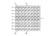
図1は、実施形態による映像フレーム内の複数の画素からなるブロックに適用可能であるフィルタリング制御の方法のフローチャートである。図1の方法は、一般に、ステップS1で始まり、ここで、p0iがブロック10内の画素11、13、15、17からなる第1ラインの中で、映像フレーム内の複数の画素21、23、25、27からなる近傍ブロック20へのブロック境界1に最も近接している画素11の画素値を表し、p1iが画素11、13、15、17からなる第1のライン12の中で、ブロック境界1に2番目に近接している画素13の画素値を表し、p2iが画素11、13、15、17からなる第1のライン12の中で、ブロック境界10に3番目に近接している画素15の画素値を表すとすると、第1のフィルタ決定値が少なくとも|p2i−2p1i+p0i|に基づいて計算される。
FIG. 1 is a flowchart of a filtering control method applicable to a block composed of a plurality of pixels in a video frame according to an embodiment. The method of FIG. 1 generally begins at step S1, where p0 i is a plurality of
ステップS2は、少なくとも|q2i−2q1i+q0i|に基づいてブロックに対する第2のフィルタ決定値を同様に計算し、ここで、q0iは、近傍ブロック20内の画素21、23、25、27からなる対応する第1のライン22の中で、ブロック境界1に最も近接している近傍ブロック20内の画素21の画素値を表し、q1iは、画素21、23、25、27からなる対応する第1のライン22の中で、ブロック境界1に2番目に近接している近傍ブロック20の画素23の画素値を表し、q2iは、画素21、23、25、27からなる対応する第1のライン22の中で、ブロック境界1に3番目に近接している近傍ブロック20内の画素25の画素値を表す。
Step S2 similarly calculates a second filter decision value for the block based on at least | q2 i -2q1 i + q0 i |, where q0 i is the
ブロック10内の画素11、13、15、17からなる第1のライン12と、近傍ブロック20内の画素21、23、25、27からなる対応する第1のライン22とは、垂直境界1の上に広がる同じ画素からなる水平ライン、即ち、画素からなる行に属する、図2Aを参照されたい、又は、水平境界1の上に広がる同じ画素からなる垂直ライン、即ち、画素の列に属する、図2Bを参照されたい。それ故に、画素11、13、15、17からなる第1のライン12と、画素21、23、25、27からなる対応する第1のライン22とは、ブロック10と近傍ブロック20との間のブロック境界1に垂直である。さらに、ブロック10内の画素11、13、15、17からなる第1のライン12と、近傍ブロック20内の画素21、23、25、27からなる対応する第1のライン22とは、同じライン番号を有する。例えば、ブロック10及び近傍ブロック20がそれぞれ、8本のような、行又は列番号i=0・・・N−1を有するN本の画素からなる行又は列を備える場合、画素11、13、15、17からなる第1のライン10は、ブロック10においてライン番号iを有し、画素21、23、25、27からなる対応する第1のライン20は、近傍ブロック20において同様にライン番号iを有する。このようにして、ブロック内の画素11、13、15、17からなる第1のライン12と、近傍ブロック20内の画素21、23、25、27からなる対応する第1のライン22とは、ブロック境界1に関して対向するラインである。
The
実施形態によれば、「画素からなるライン」及び「画素からなる対応するライン」は、図2Aのように垂直ブロック境界の場合には「画素からなる行」及び「画素からなる対応する行」を表し、図2Bのように水平ブロック境界の場合には「画素からなる列」及び「画素からなる対応する列」を表す。 According to the embodiment, the “line consisting of pixels” and the “corresponding line consisting of pixels” are “rows consisting of pixels” and “corresponding rows consisting of pixels” in the case of a vertical block boundary as shown in FIG. 2A. In the case of a horizontal block boundary as shown in FIG. 2B, “columns composed of pixels” and “corresponding columns composed of pixels” are represented.
画素11、13、15、17からなる第1のライン12及び画素21、23、25、27からなる対応するライン22は、それぞれブロック10及び近傍ブロック20内の所定のラインである可能性がある。このように、画素11、13、15、17からなる第1のライン12及び画素21、23、25、27からなる対応するライン22は、フィルタリング制御が適用される各ブロック境界1に関して所定の、かつ、固定のライン番号iを有する。代替的に、画素11、13、15、17からなる第1のライン12及び画素21、23、25、27からなる対応する第1のライン22は、それぞれ現在のライン及び現在の対応するラインを表す可能性があり、このことは本書でさらに説明される。
The
ステップS1における第1のフィルタ決定値の計算とステップS2における第2のフィルタ決定値の計算とは、どんな順序でも直列に実行されることが可能であり、即ち、ステップS1がステップS2に先行するか、若しくは、ステップS2がステップS1に先行し、又は、少なくとも部分的に並列する。これらの2つのステップS1、S2の結果は、かくして、ブロック10内の画素値に基づいて計算された第1の決定値及びブロック10に対してブロック境界1の反対側にある近傍ブロック20内の画素値に基づいて計算された第2のフィルタ決定値である。より好ましくは、第1の決定値の計算は、ブロック10内の画素値だけに基づいて、従って、近傍ブロック20内のいずれの画素値にも基づくことなく実行される。同様に、第2のフィルタ決定値は、好ましくは、近傍ブロック20内の画素値だけに基づいて、従って、ブロック10内のいずれの画素値にも基づくことなく実行される。
The calculation of the first filter decision value in step S1 and the calculation of the second filter decision value in step S2 can be performed in series in any order, ie step S1 precedes step S2. Alternatively, step S2 precedes step S1, or at least partially parallel. The result of these two steps S1, S2 is thus the first decision value calculated based on the pixel values in
ステップS1において計算された第1のフィルタ決定値は、その後、ブロック境界1に対してフィルタ処理すべきブロック10内の画素11、13、15、17のライン12の中の画素の個数を判定するためにステップS3において使用される。第2のフィルタ決定値は、ブロック境界1に対してフィルタ処理すべき近傍ブロック20内の画素21、23、25、27からなる対応するライン22の中の画素の個数を判定するためにステップS4において同様に使用される。このようにして、別個のフィルタ決定値がブロック境界1の上に広がる画素の行若しくは列のどちらの側若しくはどちらの部分に対しても計算され、それぞれのフィルタ決定がそれぞれの側若しくは部分に対して計算された特有のフィルタ決定値に基づいてそれぞれの側若しくは部分に対して採用される。
The first filter decision value calculated in step S1 then determines the number of pixels in the
これは、単一又は1組のフィルタ決定値が画素からなるライン及び画素からなる対応するラインに対して計算され、このフィルタ決定値又はフィルタ決定値の組がブロック境界の両側でフィルタ処理すべき画素の個数を決定するために使用される従来技術と比較されるべきである。このようにして、従来技術では、ブロック内のマッチングする画素からなるラインに対して行われた場合と同じ個数の画素が近傍ブロック内の画素からなる対応するラインに対して常にフィルタ処理される。 This is a single or set of filter decision values calculated for a line of pixels and a corresponding line of pixels, and this filter decision value or set of filter decision values should be filtered on both sides of the block boundary It should be compared with the prior art used to determine the number of pixels. In this way, in the prior art, the same number of pixels is always filtered for the corresponding line of pixels in the neighboring block as performed for the line of matching pixels in the block.
本実施形態は、その代わりに、ブロック10内の画素11、13、15、17のライン12に対する別個のフィルタ決定と、近傍ブロック20内の画素21、23、25、27からなる対応するライン22に対する別の様々なフィルタ決定とを行うことにより、非対称のフィルタリング制御及びデブロッキング・フィルタリングを可能にする。これは、特有の第1及び第2のフィルタ決定値に基づいて、デブロッキング・フィルタリング及び修正のため選択された画素21、23、25、27からなる対応するライン22の中の画素の個数と異なるか、又は、同数である画素11、13、15、17からなるライン12の中の画素の個数がデブロッキング・フィルタリング及び修正に対して選択され得ることを意味する。
This embodiment instead has a separate filter decision for
一般に、本書では、pXyは、ブロック10内のライン番号yを有する画素からなるラインの中のブロック境界1に相対的な画素番号Xの画素値を表す。同様に、qXyは、近傍ブロック20内のライン番号yを有する画素からなる対応するラインの中のブロック境界1に相対的な画素番号Xの画素値を表す。
In general, in this document, pX y represents the pixel value of pixel number X relative to block boundary 1 in a line consisting of pixels having line number y in
ステップS3及びS4は、どんな順序でも直列に、又は、少なくとも部分的に並列に実行されることが可能である。 Steps S3 and S4 can be performed in any order in series or at least partially in parallel.
第1の実施形態では、ステップS1及びS2は、ブロック10と近傍ブロック20との間の所与のブロック境界1に対して1回実行されることが可能であり、それによって、ブロック10内の画素11、13、15、17からなる全てのライン12、及び、近傍ブロック20内の画素21、23、25、27からなる対応する全てのライン22にそれぞれ適用できる第1のフィルタ決定値及び第2のフィルタ決定値を計算する。このようなアプローチでは、同じ第1の個数の画素が、好ましくは、ブロック境界1に関してブロック10内の画素11、13、15、17からなる各ライン12の中でフィルタ処理され、修正され、ここで、この第1の個数は、ステップS1において計算された第1のフィルタ決定値に基づいて判定される。同様に、同じ第2の個数の画素が、好ましくは、ブロック境界1に関して近傍ブロック20内の画素21、23、25、27からなる1つずつの対応するライン22の中でフィルタ処理され、修正され、ここで、この第2の個数は、ステップS2において計算された第2のフィルタ決定値に基づいて判定される。
In the first embodiment, steps S1 and S2 can be performed once for a given block boundary 1 between
代替的に、第2の実施形態では、第1のフィルタ決定値及び第2のフィルタ決定値は、ブロック10内の画素11、13、15、17からなるライン12のサブセット及び近傍ブロック20内の画素21、23、25、27からなる対応するライン22の対応するサブセットに適用できる。例えば、フィルタ決定値のペアは、ブロック内の画素11、13、15、17からなる最初の4本のライン12と、近傍ブロック20内の画素21、23、25、27からなる最初の4本の対応するライン22とのため使用されることが可能であり、フィルタ決定値の別のペアは、ブロック内の画素11、13、15、17からなる残りの4本のライン12と、近傍ブロック20内の画素21、23、25、27からなる残りの4本の対応するライン22とのため使用される。
Alternatively, in the second embodiment, the first filter decision value and the second filter decision value are a subset of the
第3の実施形態では、ステップS1における計算は、ブロック10内の画素11、13、15、17からなるライン12毎に実行され、ステップS3における別個の判定が次に画素11、13、15、17からなるこのようなライン12毎に実行される。このような場合、ステップS2における計算は、近傍ブロック20内の画素21、23、25、27からなる対応するライン22毎に同様に実行され、ステップS4における別個の判定は、画素21、23、25、27からなるこのような対応するライン22毎に実行される。
In the third embodiment, the calculation in step S1 is performed for each
このようにして、第3の実施形態では、ステップS3は、ステップS1において計算された第1のフィルタ決定値に基づいてブロック境界1に対してフィルタ処理すべきブロック10内の画素11、13、15、17からなる第1のライン12の中の画素の個数を決定するステップを備える。ステップS4は、ステップS2において計算された第2のフィルタ決定値に基づいてブロック境界1に対してフィルタ処理すべき近傍ブロック20内の画素21、23、25、27からなる対応する第1のライン22の中の画素の個数を決定するステップを備える。
In this manner, in the third embodiment, step S3 includes the
以下の部分は、どのようにして第3の実施形態がブロック境界1を横断するライン(行又は列)毎に別々に適用されるかを説明する。本例では、第1のフィルタ決定値は、
dpi=|p2i−2p1i+p0i|
として定義され、第2のフィルタ決定値は、
dqi=|q2i−2q1i+q0i|
として定義される。この方法は、その結果、以下を備える:
●ブロック境界を横断する各ラインiに対して、dpiを計算し、dqiを計算する。
●dpi<thr1である場合、
○現在のブロック10のラインiの標準フィルタリングを行う、例えば、ブロックボーダー又は境界からの2個の画素をフィルタ処理し、修正する。
●そうではない場合、即ち、dpi≧thr1である場合、
○現在のブロック10のラインiのブロックボーダー又は境界からの第2の画素をフィルタ処理しない、又は、現在のブロック10のラインi上の画素を全くフィルタ処理しない。
●dqi<thr2である場合、
○近傍ブロック20のラインiの標準フィルタリングを行い、例えば、ブロックボーダー又は境界1からの2個の画素をフィルタ処理し、修正する。
●そうではない場合、即ち、dqi≧thr2である場合、
○近傍ブロック20のラインiのブロックボーダー又は境界1からの第2の画素をフィルタ処理しない、又は、近傍ブロック20のラインi上の画素を全くフィルタ処理しない。
The following part explains how the third embodiment is applied separately for each line (row or column) crossing the block boundary 1. In this example, the first filter decision value is
d pi = | p2 i -2p1 i + p0 i |
And the second filter decision value is
d qi = | q2 i -2q1 i + q0 i |
Is defined as This method consequently comprises:
Calculate d pi and d qi for each line i that crosses the block boundary.
If d pi <thr1,
O Perform standard filtering on line i of the
If not, i.e. d pi ≥ thr1,
O Do not filter the second pixel from the block border or boundary of line i of
If d qi <thr2,
Perform standard filtering of line i of neighboring
If not, i.e. d qi ≥ thr2,
O Do not filter the second pixel from the block border or boundary 1 of line i of neighboring
上記例により示されるように、図1における方法の第3の実施形態は、別個の第1及び第2のフィルタ決定値を計算し、その結果、ブロック境界1に対しては、ブロック10及び近傍ブロック20内の各行又は列に対してフィルタ処理すべき画素の個数の別個の決定を行うことが可能である。このように、第3の実施形態では、第1及び第2のフィルタ決定値は、ラインに固有のフィルタ決定値であり、即ち、ブロック10内の画素11、13、15、17からなる各ライン12に対して、及び、近傍ブロック20内の画素21、23、25、27からなる対応する各ライン22に対して計算される。
As shown by the above example, the third embodiment of the method in FIG. 1 computes separate first and second filter decision values, so that for block boundary 1, block 10 and the neighborhood A separate determination of the number of pixels to be filtered for each row or column in
第1の実施形態では、ブロックに固有のフィルタ決定値が使用される。かくして、このような場合、単一の第1のフィルタ決定値がブロック境界1についてはブロック10に対して計算され、特有のブロック境界1に関してブロック10内の画素11、13、15、17からなる全てのライン12に適用することが可能である。同様に、単一の第2のフィルタ決定値がブロック境界1については近傍ブロック20に対して計算され、特有のブロック境界1に関して近傍ブロック20内の画素21、23、25、27からなる全ての対応するライン22に適用することが可能である。
In the first embodiment, block specific filter decision values are used. Thus, in such a case, a single first filter decision value is calculated for block boundary 1 for
第1の実施形態の第1の例は、|p22−2p12+p02|+|p25−2p15+p05|として第1のフィルタ決定値を計算するステップを含み、ここで、p02は、画素からなる第1のラインの中で、ブロック境界1に最も近接している画素の画素値を表し、p12は、画素からなる第1のラインの中で、ブロック境界1に2番目に近接している画素の画素値を表し、p22は、画素からなる第1のラインの中で、ブロック境界1に3番目に近接している画素の画素値を表し、p05は、ブロック10内の画素からなる第2のラインの中で、ブロック境界1に最も近接している画素の画素値を表し、p15は、画素からなる第2のラインの中で、ブロック境界1に2番目に近接している画素の画素値を表し、p25は、画素からなる第2のラインの中で、ブロック境界1に3番目に近接している画素の画素値を表す。
The first example of the first embodiment includes calculating a first filter decision value as | p2 2 −2p1 2 + p0 2 | + | p2 5 −2p1 5 + p0 5 |, where p0 2 Represents the pixel value of the pixel closest to the block boundary 1 in the first line of pixels, and p12 is the second value on the block boundary 1 in the first line of pixels. It represents a pixel value of a pixel in proximity to, p2 2, within the first line of pixels represents the pixel values of pixels that are close to the third block boundary 1, p0 5 is
第2のフィルタ決定値は、次に、好ましくは、|q22−2q12+q02|+|q25−2q15+q05|として計算され、ここで、q02は、画素からなる対応する第1のラインの中で、ブロック境界1に最も近接している近傍ブロック20内の画素の画素値を表し、q12は、画素からなる対応する第1のラインの中で、ブロック境界1に2番目に近接している近傍ブロック20の画素の画素値を表し、q22は、画素からなる対応する第1のラインの中で、ブロック境界1に3番目に近接している近傍ブロック20内の画素の画素値を表し、q05は、近傍ブロック20内の画素からなる対応する第2のラインの中で、ブロック境界1に最も近接している近傍ブロック20内の画素の画素値を表し、q15は、画素からなる対応する第2のラインの中で、ブロック境界1に2番目に近接している近傍ブロック20の画素の画素値を表し、q25は、画素からなる対応する第2のラインの中で、ブロック境界1に3番目に近接している近傍ブロック20内の画素の画素値を表す。
The second filter decision value is then preferably calculated as | q2 2 −2q1 2 + q0 2 | + | q2 5 −2q1 5 + q0 5 |, where q0 2 corresponds to the corresponding second number of pixels. 1 represents the pixel value of the pixel in the neighboring
第1のフィルタ決定値は、その結果、フィルタ処理すべき画素の個数を判定するときにブロック10内の画素11、13、15、17からなる全てのライン12のため使用され、第2のフィルタ決定値は、フィルタ処理すべき画素の個数を決定するときに近傍ブロック20内の画素21、23、25、27からなる全ての対応するライン22のため使用される。
The first filter decision value is then used for all
第1の実施形態のこの第1の例では、画素からなる第1のラインは、ラインi=2に対応し、対応する第1のラインは、対応するラインi=2に対応し、画素からなる第2のラインは、ラインi=5に対応し、第2の対応するラインは、対応するラインi=5に対応する。この場合、ブロック10は、好ましくは、8本のラインからなり、近傍ブロック20は、好ましくは、同様に、8本のラインからなり、即ち、i=0〜7である。
In this first example of the first embodiment, the first line of pixels corresponds to line i = 2, the corresponding first line corresponds to the corresponding line i = 2, and from the pixel This second line corresponds to line i = 5, and the second corresponding line corresponds to corresponding line i = 5. In this case, the
以下の部分は、第1の実施形態の実装例を示す。本実装例では、第1のフィルタ決定値は、dp=|p22−2p12+p02|+|p25−2p15+p05|として定義され、第2のフィルタ決定値は、dq=|q22−2q12+q02|+|q25−2q15+q05|として定義される。
●dpを計算し、dqを計算する。
●dp<thr1である場合、
○現在のブロック10の標準フィルタリングを行う、例えば、ブロックボーダー又は境界からの2個の画素をフィルタ処理し、修正する。
●そうではない場合、即ち、dp≧thr1である場合、
○ブロックボーダー又は境界1からの第2の画素をフィルタ処理しない、又は、画素を全くフィルタ処理しない。
●dq<thr2である場合、
○近傍ブロック20の標準フィルタリングを行い、例えば、ブロックボーダー又は境界1からの2個の画素をフィルタ処理し、修正する。
●そうではない場合、即ち、dq≧thr2である場合、
○ブロックボーダー又は境界1からの第2の画素をフィルタ処理しない、又は、画素を全くフィルタ処理しない。
The following part shows an implementation example of the first embodiment. In this implementation example, the first filter decision value is defined as d p = | p2 2 −2p1 2 + p0 2 | + | p2 5 −2p1 5 + p0 5 |, and the second filter decision value is d q = | Q2 2 −2q1 2 + q0 2 | + | q2 5 −2q1 5 + q0 5 |
● Calculate the d p, to calculate the d q.
If d p <thr1,
O Perform standard filtering of the
● Otherwise, that is, when d p ≧ thr1,
O Do not filter the second pixel from the block border or boundary 1, or do not filter the pixel at all.
If d q <thr2,
Perform standard filtering of neighboring
If not, i.e. d q ≥ thr2,
O Do not filter the second pixel from the block border or boundary 1, or do not filter the pixel at all.
第1の実施形態の第2の例では、第1のフィルタ決定値は、ラインi=2及びラインi=5の代わりにラインi=3及びラインi=4の中の画素値に基づいてブロックに固有のフィルタ決定値として計算される。近傍ブロック20内の対応するラインi=3及びi=4は、好ましくは、その結果、第2のフィルタ決定値を計算するため使用される。第1のフィルタ決定値は、その結果、|p23−2p13+p03|+|p24−2p14+p04|として計算される可能性があり、第2のフィルタ決定値は、|q23−2q13+q03|+|q24−2q14+q04|として計算され、ここで、p03は、画素からなる第1のラインの中で、ブロック境界1に最も近接している画素の画素値を表し、p13は、画素からなる第1のラインの中で、ブロック境界1に2番目に近接している画素の画素値を表し、p23は、画素からなる第1のラインの中で、ブロック境界1に3番目に近接している画素の画素値を表し、p04は、ブロック10内の画素からなる第2のラインの中で、ブロック境界1に最も近接している画素の画素値を表し、p14は、画素からなる第2のラインの中で、ブロック境界1に2番目に近接している画素の画素値を表し、p24は、画素からなる第2のラインの中で、ブロック境界1に3番目に近接している画素の画素値を表し、q03は、画素からなる対応する第1のラインの中で、ブロック境界1に最も近接している近傍ブロック20内の画素の画素値を表し、q13は、画素からなる対応する第1のラインの中で、ブロック境界1に2番目に近接している近傍ブロック20の画素の画素値を表し、q23は、画素からなる対応する第1のラインの中で、ブロック境界1に3番目に近接している近傍ブロック20内の画素の画素値を表し、q04は、近傍ブロック20内の画素からなる対応する第2のラインの中で、ブロック境界1に最も近接している近傍ブロック20内の画素の画素値を表し、q14は、画素からなる対応する第2のラインの中で、ブロック境界1に2番目に近接している近傍ブロック20の画素の画素値を表し、q24は、画素からなる対応する第2のラインの中で、ブロック境界1に3番目に近接している近傍ブロック20内の画素の画素値を表す。
In the second example of the first embodiment, the first filter decision value is blocked based on the pixel values in line i = 3 and line i = 4 instead of line i = 2 and line i = 5. It is calculated as a filter decision value specific to. The corresponding lines i = 3 and i = 4 in the
第2の実施形態では、第1のフィルタ決定値及び第2のフィルタ決定値は、画素からなる4本のライン及び画素からなる4本の対応するラインのグループに対して計算される。この第2の実施形態は、ブロック及び近傍ブロックがそれぞれ4×4画素のサイズを有する場合に適当である可能性がある。さらに、第2の実施形態は、8×8画素のような画素からなるより大きいブロックのため使用される可能性もある。後者の場合、フィルタ決定のペアは、最初の4本のライン画素及び画素からなる最初の4本の対応するラインに対して計算され、フィルタ決定の別のペアは、画素からなる残りの4本のライン及び画素からなる残りの4本の対応するラインに対して計算される。 In the second embodiment, the first filter decision value and the second filter decision value are calculated for a group of four lines of pixels and four corresponding lines of pixels. This second embodiment may be appropriate when the blocks and neighboring blocks each have a size of 4 × 4 pixels. Furthermore, the second embodiment may be used for larger blocks of pixels such as 8x8 pixels. In the latter case, a filter decision pair is calculated for the first four line pixels and the first four corresponding lines of pixels, and another pair of filter decisions is the remaining four pixels. For the remaining four corresponding lines of pixels and pixels.
第2の実施形態の第1の例は、|p20−2p10+p00|+|p23−2p13+p03|として第1のフィルタ決定値を計算し、|q20−2q10+q00|+|q23−2q13+q03|として第2のフィルタ決定値を計算する。この場合、画素からなるライン及び画素からなる対応するラインは、ライン番号i=0からライン番号i=3まで続く可能性がある。図2A及び2Bに示されるようにi=0〜7のような画素からなるより大規模なブロックに対し、第1のフィルタ決定値及び第2のフィルタ決定値の第1のペアは、|p20−2p10+p00|+|p23−2p13+p03|及び|q20−2q10+q00|+|q23−2q13+q03|として計算される。フィルタ決定値のこの第1のペアは、画素からなる最初の4本のラインと画素からなる最初の4本の対応するライン、即ち、i=0〜3に適用可能である。第1のフィルタ決定値及び第2のフィルタ決定値の第2のペアは、その結果、|p24−2p14+p04|+|p27−2p17+p07|及び|q24−2q14+q04|+|q27−2q17+q07|として計算される。フィルタ決定値の第2のペアは、その結果、画素からなる4本の最後のラインと画素からなる4本の最後の対応するライン、即ち、i=4〜7に適用可能である。 In the first example of the second embodiment, the first filter determination value is calculated as | p2 0 −2p1 0 + p0 0 | + | p2 3 −2p1 3 + p0 3 |, and | q2 0 −2q1 0 + q0 0 The second filter determination value is calculated as | + | q2 3 −2q1 3 + q0 3 |. In this case, the line consisting of pixels and the corresponding line consisting of pixels may continue from line number i = 0 to line number i = 3. For larger blocks of pixels such as i = 0-7 as shown in FIGS. 2A and 2B, the first pair of first filter decision value and second filter decision value is | p2 0 −2p1 0 + p0 0 | + | p2 3 −2p1 3 + p0 3 | and | q2 0 −2q1 0 + q0 0 | + | q2 3 −2q1 3 + q0 3 | This first pair of filter decision values is applicable to the first four lines of pixels and the first four corresponding lines of pixels, i = 0-3. The second pair of the first filter decision value and the second filter decision value results in | p2 4 -2p1 4 + p0 4 | + | p2 7 -2p1 7 + p0 7 | and | q2 4 -2q1 4 + q0 4 | + | q2 7 -2q1 7 + q0 7 | The second pair of filter decision values is consequently applicable to the four last lines of pixels and the four last corresponding lines of pixels, i = 4-7.
第2の実施形態の第2の例は、|p21−2p11+p01|+|p22−2p12+p02|として第1のフィルタ決定値を計算し、|q21−2q11+q01|+|q22−2q12+q02|として第2のフィルタ決定値を計算する。この場合、画素からなるライン及び画素からなる対応するラインは、ライン番号i=0からライン番号i=3まで続く可能性がある。図2A及び2Bに示されるようにi=0〜7のような画素からなるより大規模なブロックに対し、第1のフィルタ決定値及び第2のフィルタ決定値の第1のペアは、|p21−2p11+p01|+|p22−2p12+p02|及び|q21−2q11+q01|+|q22−2q12+q02|として計算される。フィルタ決定値のこの第1のペアは、画素からなる最初の4本のラインと画素からなる最初の4本の対応するライン、即ち、i=0〜3に適用可能である。第1のフィルタ決定値及び第2のフィルタ決定値の第2のペアは、その結果、|p25−2p15+p05|+|p26−2p16+p06|及び|q25−2q15+q05|+|q26−2q16+q06|として計算される。フィルタ決定値の第2のペアは、その結果、画素からなる4本の最後のラインと画素からなる4本の最後の対応するライン、即ち、i=4〜7に適用可能である。 In the second example of the second embodiment, the first filter determination value is calculated as | p2 1 −2p1 1 + p0 1 | + | p2 2 −2p1 2 + p0 2 |, and | q2 1 −2q1 1 + q0 1 The second filter decision value is calculated as | + | q2 2 −2q1 2 + q0 2 |. In this case, the line consisting of pixels and the corresponding line consisting of pixels may continue from line number i = 0 to line number i = 3. For larger blocks of pixels such as i = 0-7 as shown in FIGS. 2A and 2B, the first pair of first filter decision value and second filter decision value is | p2 1 −2p1 1 + p0 1 | + | p2 2 −2p1 2 + p0 2 | and | q2 1 −2q1 1 + q0 1 | + | q2 2 −2q1 2 + q0 2 | This first pair of filter decision values is applicable to the first four lines of pixels and the first four corresponding lines of pixels, i = 0-3. The second pair of first and second filter decision values results in | p2 5 -2p1 5 + p0 5 | + | p2 6 -2p1 6 + p0 6 | and | q2 5 -2q1 5 + q0 5 | + | q2 6 -2q1 6 + q0 6 | The second pair of filter decision values is consequently applicable to the four last lines of pixels and the four last corresponding lines of pixels, i = 4-7.
第2の実施形態のこの概念は、第1のフィルタ決定値がブロック内の画素からなるラインのサブセットに存在する画素の画素値に基づいて計算され、第2のフィルタ決定値が近傍ブロック内の画素からなる対応するラインのサブセットに存在する画素の画素値に基づいて計算される場合に拡張され得る。このようにして、第2の実施形態のこの一般的概念では、第1のフィルタ決定値は、|p2i−2p1i+p0i|+|p2j−2p1j+p0j|として計算される可能性があり、ここで、i、jは、区間0からN−1における異なるライン番号を表現し、Nは、ブロック及び近傍ブロック内の画素からなるラインの総数を表し、i≠jである。第2のフィルタ決定値は、その結果、好ましくは、|q2i−2q1i+q0i|+|q2j−2q1j+q0j|として計算される。この概念は、当然ながら、画素からなるライン又は画素からなる対応するラインのうちの3本以上を格納するサブセットを用いて拡張され得る。 This concept of the second embodiment is that the first filter decision value is calculated based on the pixel values of the pixels present in the subset of lines consisting of the pixels in the block, and the second filter decision value is calculated in the neighboring block. It can be extended if it is calculated based on the pixel values of the pixels present in the corresponding subset of lines of pixels. Thus, in this general concept of the second embodiment, the first filter decision value may be calculated as | p2 i −2p1 i + p0 i | + | p2 j −2p1 j + p0 j |. Here, i and j represent different line numbers in the sections 0 to N−1, and N represents the total number of lines composed of pixels in the block and neighboring blocks, where i ≠ j. The second filter decision value is therefore preferably calculated as | q2 i −2q1 i + q0 i | + | q2 j −2q1 j + q0 j |. This concept can, of course, be extended with a subset that stores three or more of the lines of pixels or the corresponding lines of pixels.
第1又は第3の実施形態の関連例では、第1のフィルタ決定値は、

第4の実施形態では、ブロックに固有のフィルタ決定値及びラインに固有のフィルタ決定値の組み合わせがブロック内の画素からなるライン及び近傍ブロック内の画素からなる対応するラインに対してフィルタ処理すべき画素の個数を判定するために使用される。図3は、このような実施形態を概略的に示す。この方法は、第3のフィルタ決定値が|p22−2p12+p02|+|p25−2p15+p05|として計算されるステップS10で始まり、ここで、p02は、ブロック10内の画素からなる第2のラインの中で、ブロック境界1に最も近接している画素の画素値を表し、p12は、画素からなる第2のラインの中で、ブロック境界1に2番目に近接している画素の画素値を表し、p22は、画素からなる第2のラインの中で、ブロック境界1に3番目に近接している画素の画素値を表し、p05は、ブロック10内の画素からなる第3のラインの中で、ブロック境界1に最も近接している画素の画素値を表し、p15は、画素からなる第3のラインの中で、ブロック境界1に2番目に近接している画素の画素値を表し、p25は、画素からなる第3のラインの中で、ブロック境界1に3番目に近接している画素の画素値を表す。画素からなる第2のラインは、好ましくは、ブロック10内のライン番号2に対応し、画素からなる第3のラインは、好ましくは、ブロック10内のライン番号5に対応する。図2A及び2Bを参照されたい。
In the fourth embodiment, a combination of a filter determination value specific to a block and a filter determination value specific to a line should be filtered for a line made up of pixels in the block and a corresponding line made up of pixels in a neighboring block. Used to determine the number of pixels. FIG. 3 schematically illustrates such an embodiment. The method begins at step S10 where the third filter decision value is calculated as | p2 2 −2p1 2 + p0 2 | + | p2 5 −2p1 5 + p0 5 |, where p0 2 Represents the pixel value of the pixel closest to block boundary 1 in the second line of pixels, and p12 is the second closest to block boundary 1 in the second line of pixels to and represents a pixel value of the pixel, p2 2, within the second line of pixels represents the pixel values of pixels that are close to the third block boundary 1, p0 5 is
次のステップS11は、第4のフィルタ決定値を|q22−2q12+q02|+|q25−2q15+q05|として計算し、ここで、q02は、近傍ブロック20内の画素からなる対応する第2のラインの中で、ブロック境界1に最も近接している近傍ブロック20内の画素の画素値を表し、q12は、画素からなる対応する第2のラインの中で、ブロック境界1に2番目に近接している近傍ブロック20の画素の画素値を表し、q22は、画素からなる対応する第2のラインの中で、ブロック境界1に3番目に近接している近傍ブロック20内の画素の画素値を表し、q05は、近傍ブロック20内の画素からなる対応する第3のラインの中で、ブロック境界1に最も近接している近傍ブロック20内の画素の画素値を表し、q15は、画素からなる対応する第3のラインの中で、ブロック境界20に2番目に近接している近傍ブロック20の画素の画素値を表し、q25は、画素からなる対応する第3のラインの中で、ブロック境界1に3番目に近接している近傍ブロック20内の画素の画素値を表す。画素からなる第2の対応するラインは、好ましくは、近傍ブロック20内のライン番号2に対応し、画素からなる第3の対応するラインは、好ましくは、近傍ブロック20内のライン番号5に対応する。図2A及び2Bを参照されたい。
The next step S11 calculates the fourth filter decision value as | q2 2 −2q1 2 + q0 2 | + | q2 5 −2q1 5 + q0 5 |, where q0 2 is calculated from the pixels in the neighboring
ステップS10及びS11は、どんな順序でも直列に、又は、少なくとも部分的に並列に実行されることが可能である。 Steps S10 and S11 can be performed in any order in series or at least partially in parallel.
次のステップS12は、ステップS10で計算された第3のフィルタ決定値を第3の閾値(T3)と比較する。第3のフィルタ決定値が第3の閾値未満である場合、この方法は、図1のステップS1とその後にステップS3とに続く。従って、このような場合、それぞれのラインに固有の、又は、第1のフィルタ決定値は、ブロック10内のラインi毎に計算され、ここで、iは、好ましくは、0から7までである。この第1のフィルタ決定値は、その結果、図1のステップS1において|p2i−2p1i+p0i|として計算される。図1のステップS3は、ステップS1において画素からなるラインiに対して計算された第1のフィルタ決定値に基づいてブロック境界1に対してフィルタ処理すべきブロック10内の画素からなるラインiの中の画素の個数を判定する。この手順は、ブロック10内の画素からなるライン毎に実行される。このようにして、図2A又は2Bに示されるようなブロック10を使って、ステップS1及びS3は、8回実行されることになる。この方法は、その後、図3のステップS13に続く。同様に、第3のフィルタ決定値がステップS12において第3の閾値未満ではない場合、この方法は、ステップS13に続く。
In the next step S12, the third filter determination value calculated in step S10 is compared with the third threshold value (T 3 ). If the third filter decision value is less than the third threshold value, the method continues to step S1 in FIG. 1 followed by step S3. Thus, in such a case, a unique or first filter decision value for each line is calculated for each line i in the
ステップS13は、ステップS11で計算された第4のフィルタ決定値を第4の閾値(T4)と比較する。第4のフィルタ決定値が第4の閾値未満である場合、この方法は、図1のステップS2及びS4に続く。それぞれのラインに固有の、又は、第2のフィルタ決定値は、近傍ブロック20内の対応するラインi毎に図1のステップS2において|q2i−2q1i+q0i|として計算される。図3のステップS4は、ステップS2において画素からなる対応するラインiに対して計算された第2のフィルタ決定値に基づいてブロック境界1に対してフィルタ処理すべき近傍ブロック20内の画素からなる対応するラインiの中の画素の個数を判定する。この手順は、近傍ブロック20内の画素からなる対応するライン毎に実行される。この方法は、その後、終了する。同様に、第4のフィルタ決定値がステップS13において第4の閾値未満ではない場合、この方法は、終了する。
In step S13, the fourth filter determination value calculated in step S11 is compared with a fourth threshold value (T 4 ). If the fourth filter decision value is less than the fourth threshold, the method continues to steps S2 and S4 of FIG. A unique or second filter decision value for each line is calculated as | q2 i -2q1 i + q0 i | for each corresponding line i in the
ステップS12、S1及びS3により形成されるループは、ステップS13、S2及びS4により形成されるループに対してどのような順序でも順次に、又は、少なくとも部分的に並列に実行され得る。
The loop formed by steps S12, S1 and S3 can be executed in any order sequentially or at least partially in parallel with the loop formed by steps S13, S2 and S4.
この第4の実施形態の例では、ブロックベースの非対称フィルタ決定とラインベースの非対称フィルタ決定との組み合わせが使用される。本例では、第3のフィルタ決定値は、dp=|p22−2p12+p02|+|p25−2p15+p05|として計算され、第4のフィルタ決定値は、dq=|q22−2q12+q02|+|q25−2q15+q05|として計算される。ラインに固有のフィルタ決定値、即ち、第1及び第2のフィルタ決定値は、ライン及び対応するライン番号iに対してそれぞれdpi=|p2i−2p1i+p0i|及びdqi=|q2i−2q1i+q0i|として計算される。
●dpを計算し、dqを計算する。
●dp<thr1である場合、
○ラインi毎に
■ラインiに対するdpiを計算する。
■dpi<thr1である場合、
●現在のブロック10内のラインi、例えば、ブロックボーダー又は境界1からの2個の画素の標準フィルタリングを行う。
■そうではない場合、即ち、dpi≧thr1である場合、
●現在のブロック10のラインiのブロックボーダー又は境界1からの第2の画素をフィルタ処理しない、又は、現在のブロック10のラインi上の画素を全くフィルタ処理しない。
●そうではない場合、即ち、dp≧thr1である場合、
○ブロックボーダー又は境界1からの第2の画素をフィルタ処理しない、又は、画素を全くフィルタ処理しない。
●dq<thr2である場合、
○ラインi毎に
■ラインiに対するdqiを計算する。
■dqi<thr2である場合、
●近傍ブロック20内のラインi、例えば、ブロックボーダー又は境界1からの2個の画素の標準フィルタリングを実行する。
■そうではない場合、即ち、dqi≧thr2である場合、
●近傍ブロック20のラインiのブロックボーダー又は境界1からの第2の画素をフィルタ処理しない、又は、近傍ブロック20のラインi上の画素を全くフィルタ処理しない。
●そうではない場合、即ち、dq≧thr2である場合、
○ブロックボーダー又は境界1からの第2の画素をフィルタ処理しない、又は、画素を全くフィルタ処理しない。
In the fourth embodiment example, a combination of block-based asymmetric filter determination and line-based asymmetric filter determination is used. In this example, the third filter decision value is calculated as d p = | p2 2 -2p1 2 + p0 2 | + | p2 5 -2p1 5 + p0 5 |, and the fourth filter decision value is d q = | q2 2 −2q1 2 + q0 2 | + | q2 5 −2q1 5 + q0 5 | The line specific filter decision values, i.e. the first and second filter decision values, are d pi = | p2 i -2p1 i + p0 i | and d qi = | q2 for the line and the corresponding line number i, respectively. i −2q1 i + q0 i |
● Calculate the d p, to calculate the d q.
If d p <thr1,
○ For each line i (1) Calculate d pi for line i.
When d pi <thr1,
Perform standard filtering of the two pixels from line i in the
■ Otherwise, that is, when d pi ≥ thr1
Do not filter the second pixel from the block border or boundary 1 of line i of
● Otherwise, that is, when d p ≧ thr1,
O Do not filter the second pixel from the block border or boundary 1, or do not filter the pixel at all.
If d q <thr2,
○ For each line i (1) Calculate d qi for line i.
When d qi <thr2,
Perform standard filtering of two pixels from a line i in the
■ Otherwise, that is, when d qi ≧ thr2
Do not filter the second pixel from the block border or boundary 1 of line i of neighboring
If not, i.e. d q ≥ thr2,
O Do not filter the second pixel from the block border or boundary 1, or do not filter the pixel at all.
上記開示された例では、第3のフィルタ決定値及び第1のフィルタ決定値を比較するときに同じ閾値、即ち、thr1が使用され、そして、第4のフィルタ決定値及び第2のフィルタ決定値を比較するときに同じ閾値、即ち、thr2が使用されている。代替的なアプローチでは、第3の閾値は、第3のフィルタ決定値のため使用され、第1の閾値は、第1のフィルタ決定値のため使用され、第4の閾値は、第4のフィルタ決定値のため使用され、第2の閾値は、第2のフィルタ決定値のため使用される。特有の実施形態では、第3の閾値及び第4の閾値は等しく、第1の閾値及び第2の閾値は等しい。 In the example disclosed above, the same threshold, ie thr1, is used when comparing the third filter decision value and the first filter decision value, and the fourth filter decision value and the second filter decision value. The same threshold, ie thr2, is used when comparing. In an alternative approach, the third threshold is used for the third filter decision value, the first threshold is used for the first filter decision value, and the fourth threshold is the fourth filter value. A second threshold is used for the decision value and a second threshold is used for the second filter decision value. In a specific embodiment, the third threshold and the fourth threshold are equal, and the first threshold and the second threshold are equal.
図4は、図1の判定ステップS3及びS4の特有の実施形態を示すフローチャートである。この方法は、図1におけるステップS2から続く。次のステップS20は、図1のステップS1で計算された第1のフィルタ決定値(dp)を第1の閾値(T1)と比較する。第1のフィルタ決定値が第1の閾値未満である場合、この方法は、ステップS20からステップS21に続く。ステップS21は、ブロック境界1に対してブロック10内の画素11、13、15、17からなるライン12の中の2個の画素をフィルタ処理することを判定する。これらの2個の画素は、好ましくは、画素11、13、15、17からなるライン12の中で、ブロック境界1に最も近接している画素11、及び、ブロック境界1に2番目に近接している画素13である。しかし、第1のフィルタ決定値がステップS20において第1の閾値未満ではない場合、この方法は、その代わりにステップS22に続く。ステップS22の第1の実施形態は、ブロック境界1に対してブロック10内の画素11、13、15、17からなるライン12の中の1個の画素をフィルタ処理することを判定する。この画素11は、好ましくは、画素11、13、15、17からなるライン12の中でブロック境界1に最も近接している画素11である。ステップS22の第2の実施形態は、ブロック境界1に対してブロック10内の画素11、13、15、17からなるライン12の中の画素をフィルタ処理しないことを判定する。
FIG. 4 is a flowchart showing a specific embodiment of the determination steps S3 and S4 of FIG. This method continues from step S2 in FIG. In the next step S20, the first filter determination value (d p ) calculated in step S1 in FIG. 1 is compared with the first threshold value (T 1 ). If the first filter decision value is less than the first threshold, the method continues from step S20 to step S21. In step S21, it is determined that two pixels in the
ステップS23からS25は、近傍ブロック20内の画素21、23、25、27からなる対応するライン22に対する対応する判定を実行する。このようにして、ステップS23は、図1のステップS2で計算された第2のフィルタ決定値(dq)を第2閾値(T2)と比較する。第2のフィルタ決定値が第2の閾値未満である場合、この方法は、ステップS24に続く。ステップS24は、ブロック境界1に対して近傍ブロック20内の画素21、23、25、27からなる対応するライン22の中の2個の画素をフィルタ処理することを判定する。これらの2個の画素21、23は、好ましくは、画素21、23、25からなる対応するライン22の中で、ブロック境界1に最も近接している画素21、及び、ブロック境界1に2番目に近接している画素23である。第2のフィルタ決定値が第2の閾値未満ではない場合、この方法は、代わりにステップS23からステップS25に続く。ステップS25の第1の実施形態は、ブロック境界1に対して近傍ブロック20内の画素21、23、25、27からなる対応するライン22の中で1個の画素をフィルタ処理することを判定する。この画素21は、好ましくは、画素21、23、25、27からなる対応するライン22の中で、ブロック境界1に最も近接している画素21である。ステップS25の第2の実施形態は、ブロック境界1に対して近傍ブロック内の画素21、23、25、27からなる対応するライン22の中の画素をフィルタ処理しないことを判定する。
Steps S <b> 23 to S <b> 25 execute a corresponding determination on the
ステップS20、S21及びS22は、ステップS23、S24及びS25より前に、より後に、又は、少なくとも部分的に並列に実行され得る。 Steps S20, S21 and S22 may be performed before, after or at least partially in parallel with steps S23, S24 and S25.
この概念は、1個のフィルタ決定値当たり2個以上の閾値を使用することにより拡張され得る。例えば、dp<T1である場合、2個の画素が画素11、13、15、17からなるライン12の中でフィルタ処理され、T1≦dp<T1’である場合、1個の画素が画素11、13、15、17からなるライン12の中でフィルタ処理され、dp≧T1’である場合、画素11、13、15、17からなるライン12の中で画素はフィルタ処理されない。この場合、T1<T1’である。同様に、dq<T2である場合、2個の画素が画素21、23、25、27からなる対応するライン22の中でフィルタ処理され、T2≦dq<T2’である場合、1個の画素が画素21、23、25、27からなる対応するライン22の中でフィルタ処理され、dq≧T2’である場合、画素21、23、25、27からなる対応するライン22の中で画素はフィルタ処理されない。この場合、T2<T2’である。
This concept can be extended by using more than one threshold per filter decision value. For example, if d p <T 1 , two pixels are filtered in the
このように、一般的な態様では、第1又は第2のフィルタ決定値がゼロに接近するほど、より大きい第1又は第2のフィルタ決定値と比べると、画素からなるライン又は対応するラインの中のより多くの画素をフィルタリングし、そして、もしかすると修正することにより、より多くのフィルタリングが画素からなる特有のライン又は対応するラインに適用されるべきである。これは、ゼロ又は小さい第1又は第2のフィルタ決定値が全く又は殆ど構造を暗示することなく、むしろ、映像フレーム内にかなり均一なエリアを暗示することを意味する。同様に、大きい第1又は第2のフィルタ決定値は、一般に、映像フレーム内のエリア内の局所構造を反映し、この局所構造は、抑制される若しくはフィルタで取り除かれるべきではない。 Thus, in a general aspect, the closer the first or second filter decision value is to zero, the more the first or second filter decision value is compared to the line of pixels or the corresponding line. By filtering and possibly modifying more pixels in it, more filtering should be applied to a specific line of pixels or a corresponding line. This means that a zero or small first or second filter decision value implies no or little structure, but rather implies a fairly uniform area within the video frame. Similarly, a large first or second filter decision value generally reflects a local structure within an area in the video frame, and this local structure should not be suppressed or filtered out.
本実施形態は、ブロックボーダーからの第2の画素のフィルタリングが従来技術のHEVC解決策と比べるとあまり頻繁に行われない可能性があるので、デブロッキング・フィルタリングとの関連において計算的複雑性を減少させる。 This embodiment reduces the computational complexity in the context of deblocking filtering because the filtering of the second pixel from the block border may not be performed as often as compared to the prior art HEVC solution. Decrease.
前述され、様々なフィルタ決定値を比較するために使用された閾値は、好ましくは、ブロック又は近傍ブロックに割り当てられた量子化パラメータ(QP)に依存する。図5は、このようなアプローチを概略的に示す。この方法は、ステップS30で開始し、ここで、第1のフィルタ決定値が比較される(図4のステップS20を参照)第1の閾値がブロック10に関連付けられた量子化パラメータに基づいて判定される。同様に、ステップS31は、近傍ブロック20に関連付けられた量子化パラメータ及び/又はブロック10に関連付けられた量子化パラメータに基づいて、第2のフィルタ決定値が比較される(図4のステップ23を参照)第2の閾値を決定する。
The threshold described above and used to compare the various filter decision values preferably depends on the quantization parameter (QP) assigned to the block or neighboring block. FIG. 5 schematically illustrates such an approach. The method starts at step S30, where the first filter decision values are compared (see step S20 in FIG. 4) and the first threshold is determined based on the quantization parameter associated with
例えば、T1及びT2は、ブロック10又は近傍ブロック20のQP値から判定されるパラメータβに基づいて判定される。特有の実施形態では、パラメータβは、QP値に基づいて表から読み取られる。以下の表1を参照されたい。
特定の実施形態では、T1=T2=β/6又はT1=T2=(β+β>>1)>>3である。実施形態の別の変形として、閾値は、別個の表から読み取られることが可能であり、即ち、T1=function(QP)、T2=function(QP)である。さらに、前述の第3及び第4の閾値は、好ましくは、ブロック及び近傍ブロックにそれぞれ関連付けられた量子化パラメータに基づいて判定される。 In certain embodiments, T 1 = T 2 = β / 6 or T 1 = T 2 = (β + β >> 1) >> 3. As another variation of the embodiment, the threshold can be read from a separate table, ie T 1 = function (QP), T 2 = function (QP). Further, the third and fourth thresholds are preferably determined based on quantization parameters associated with the block and neighboring blocks, respectively.
図6は、実施形態のフィルタリング制御がフィルタリングプロセスとの関連においてどのように使用され得るかを示すフローチャートである。この方法は、ステップS40で開始し、ここで、第1のオフセット又はデルタ値Δが
(9×(q0j−p0j)−3×(q1j−p1j))/16
に基づいて計算され、ここで、p0jは、画素11、13、15、17からなるライン12の中で、ブロック境界1に最も近接している画素11の画素値を表し、p1jは、画素11、13、15、17からなるライン12の中で、ブロック境界1に2番目に近接している画素13の画素値を表し、q0jは、画素21、23、25、27からなる対応するライン22の中で、ブロック境界1に最も近接している近傍ブロック20内の画素21の画素値を表し、q1jは、画素21、23、25、27からなる対応するライン22の中で、ブロック境界1に2番目に近接している近傍ブロック20の画素23の画素値を表す。
FIG. 6 is a flow chart illustrating how the filtering control of the embodiment may be used in the context of a filtering process. The method starts at step S40, where the first offset or delta value Δ is (9 × (q0 j −p0 j ) −3 × (q1 j −p1 j )) / 16.
Where p0 j represents the pixel value of the
この第1のオフセットは、第1のオフセットを画素値に加算することにより、即ち、p0’j=p0j+Δにより、画素11、13、15、17からなるライン12の中でブロック境界1に最も近接している画素11の画素値を修正するためにステップS41で使用される。ステップS41は、画素値から第1のオフセットを減算することにより、即ち、q0’j=q0j−Δにより、画素21、23、25、27からなる対応するライン22の中でブロック境界1に最も近接している画素21の画素値をさらに修正する。この方法は、次に、第1のフィルタ決定値(dp)及び第2のフィルタ決定値(dq)が計算される図1のステップS1及びS2に続く。次のステップS42は、第1のフィルタ決定値を第1の閾値(T1)と比較する。このステップS42は、図4のステップS20に対応する。第1のフィルタ決定値が閾値未満である場合、この方法は、ステップS43に続く。
This first offset is obtained by adding the first offset to the pixel value, i.e., p0 ′ j = p0 j + Δ, so that the block boundary 1 in the
ステップS43は、
(p0j+p2j−2p1j+2Δ)/4
に基づいて第2のオフセット又はデルタ値Δpを計算し、ここで、p2jは、画素11、13、15、17からなるライン12の中で、ブロック境界1に3番目に近接している画素15の画素値を表す。第2のオフセットは、その後、第2のオフセットを画素値に加算することにより、即ち、p1’j=p1j+Δpにより、画素11、13、15、17からなるライン12の中でブロック境界1に2番目に近接している画素13の画素値を修正するためにステップS44で使用される。
Step S43
(P0 j + p2 j -2p1 j + 2Δ) / 4
To calculate a second offset or delta value Δ p , where p 2 j is third closest to block boundary 1 in
この方法は、その後、ステップS45に続く。この方法は、第1のフィルタ決定値が第1の閾値未満ではない場合、図6においてステップS42からステップS45に同様に続く。 The method then continues to step S45. This method continues similarly from step S42 to step S45 in FIG. 6 if the first filter decision value is not less than the first threshold.
ステップS45は、第2のフィルタ決定値を第2の閾値(T2)と比較する。このステップS45は、図4のステップS23に対応する。第2のフィルタ決定値が第2の閾値未満である場合、この方法は、ステップS46に続く。ステップS46は、
(q0j+q2j−2q1j−2Δ)/4
に基づいて第3のオフセットΔqを計算し、ここで、q2jは、画素21、23、25、27からなる対応するライン22の中で、ブロック境界1に3番目に近接している近傍ブロック20内の画素25の画素値を表す。第3のオフセットは、第3のオフセットを画素値に加算することにより、即ち、q1’j=q1j+Δqにより、画素21、23、25、27からなる対応するライン22の中で、ブロック境界1に2番目に近接している画素23の画素値を修正するためにステップS47で使用される。
A step S45 compares the second filter decision value with the second threshold value (T 2 ). This step S45 corresponds to step S23 in FIG. If the second filter decision value is less than the second threshold, the method continues to step S46. Step S46
(Q0 j + q2 j -2q1 j -2Δ) / 4
To calculate a third offset Δ q , where q 2 j is the neighborhood closest to block boundary 1 in the
ステップS42、S43及びS44は、どんな順序でも直列に、又は、ステップS45、S46及びS47と少なくとも部分的に並列に実行されることが可能である。 Steps S42, S43 and S44 may be performed in any order in series or at least partially in parallel with steps S45, S46 and S47.
上記において、第1、第2及び第3のオフセットは、画素値の特有の方程式に基づいて計算される。これは、第1のオフセットが
(9×(q0j−p0j)−3×(q1j−p1j))/16
の関数として計算され、第2のオフセットが
(p0j+p2j−2p1j+2Δ)/4
の関数として計算され、第3のオフセットが
(q0j+q2j−2q1j−2Δ)/4
の関数として計算されることを意味する。様々なこのような関数が考えられ、ステップS40、S43及びS46で使用され得る。このような関数は、従って、オフセットの計算がハードウェアで効率的に実行されるように定義されることが可能である。このような場合、除算を含まないこと、及び/又は、オフセットが整数値であるように関数を定義しないことが一般的に好ましい。実施形態では、(X+8)>>4がX/16の整数表現として使用され、ここで、>>は、右シフト演算を表す。このように、特定の実施形態では、ステップS40は、
(9×(q0j−p0j)−3×(q1j−p1j)+8)>>4
に基づくように、かつ、好ましくは、一致するように第1のオフセットを計算する。第2及び第3のオフセットの対応する整数表現は、
(((p0j+p2j+1)>>1)−p1j+Δ)>>1
及び
(((q0j+q2j+1)>>1)−q1j−Δ)>>1
とすることができる。
In the above, the first, second and third offsets are calculated based on a specific equation for pixel values. This is because the first offset is (9 × (q0 j −p0 j ) −3 × (q1 j −p1 j )) / 16
And the second offset is (p0 j + p2 j -2p1 j + 2Δ) / 4
And the third offset is (q0 j + q2 j -2q1 j -2Δ) / 4
It is calculated as a function of. Various such functions are conceivable and can be used in steps S40, S43 and S46. Such a function can therefore be defined so that the calculation of the offset is performed efficiently in hardware. In such cases, it is generally preferred not to include division and / or not define the function such that the offset is an integer value. In an embodiment, (X + 8) >> 4 is used as an integer representation of X / 16, where >> represents a right shift operation. Thus, in certain embodiments, step S40 is
(9 × (q0 j −p0 j ) −3 × (q1 j −p1 j ) +8) >> 4
And, preferably, the first offset is calculated to match. The corresponding integer representation of the second and third offsets is
(((P0 j + p2 j +1) >> 1) −p1 j + Δ) >> 1
And (((q0 j + q2 j +1) >> 1) -q1 j -Δ) >> 1
It can be.
例として、デブロッキングの結果として修正された画素値は、以下のように計算される。本例では、第1のフィルタ決定値は、dp=|p22−2p12+p02|+|p25−2p15+p05|として定義され、第2のフィルタ決定値は、dq=|q22−2q12+q02|+|q25−2q15+q05|として定義される。
●Δ=(9×(q0−p0)−3×(q1−p1))/16
●p’0=p0+Δ
●q’0=q0−Δ
●dp<thrPである場合、
○Δp=(p0+p2−2p1+2Δ)/4
○p’1=p1+Δp
●dq<thrQである場合、
○Δq=(q0+q2−2q1−2Δ)/4
○q’1=q1+Δq
As an example, pixel values modified as a result of deblocking are calculated as follows: In this example, the first filter decision value is defined as d p = | p2 2 -2p1 2 + p0 2 | + | p2 5 -2p1 5 + p0 5 |, and the second filter decision value is d q = | q2 2 −2q1 2 + q0 2 | + | q2 5 −2q1 5 + q0 5 |
Δ = (9 × (q0−p0) −3 × (q1−p1)) / 16
● p ′ 0 = p 0 + Δ
Q ′ 0 = q 0 −Δ
If d p <thrP,
○ Δ p = (p0 + p2-2p1 + 2Δ) / 4
○ p ′ 1 = p 1 + Δ p
If d q <thrQ,
○ Δ q = (q0 + q2-2q1-2Δ) / 4
○ q ′ 1 = q 1 + Δ q
プログラミング言語による上記例の計算の正確な式は、以下のテキストのように見える可能性がある。ここで、Clip3関数は、2個の最初の関数引数の間のレンジへの出力値のクリッピングである。
Int xCalcDP(Pel* piSrc, Int iOffset)
{
return abs(piSrc[−iOffset*3]−2*piSrc[−iOffiset*2]+piSrc[−iOffset]);
}
Int xCalcDQ(Pel* piSrc, Int iOffset)
{
return abs(piSrc[0]−2*piSrc[iOffset]+piSrc[iOffset*2]);
}
Int iDP=xCalcDP(piTmpSrc+iSrcstep*(iIdx*uiPelsInPart+iBlkIdx*DEBLOCK_SMALLEST_BLOCK+2), iOffset)+xCalcDP(piTmpSrc+iSrcStep*(iIdx*uiPelsInpart+iBlkIdx*DEBLOCK_SMALLEST_BLOCK+5), iOffset);
Int iDQ=xCalcDQ(piTmpSrc+iSrcstep*(iIdx*uiPelsInPart+iBlkIdx*DEBLOCK_SMALLEST_BLOCK+2), iOffset)+xCalcDQ(piTmpSrc+iSrcStep*(iIdx*uiPelsInpart+iBlkIdx*DEBLOCK_SMALLEST_BLOCK+5), iOffset);
Int iSideThreshold=iBeta/6;
Bool bFilterP=(iDP<iSideThreshold);
Bool bFilterQ=(iDQ<iSideThreshold);
delta=(9*(m4−m3)−3*(m5−m2)+8)>>4;
if (abs(delta)<iThrCut)
{
Int tc2=tc>>1;
delta=Clip3(−tc, tc, delta);
piSrc[−iOffset]=Clip((m3+delta));
piSrc[0]=Clip((m4−delta));
if (bFilterP)
{
Int delta1=Clip3(−tc2, tc2, ((((m1+m3+1)>>1)−m2+delta)>>1));
piSrc[−iOffset*2]=Clip((m2+delta1));
}
if (bFilterQ)
{
{
Int delta2=Clip3(−tc2, tc2, ((((m6+m4+1)>>1)−m5−delta)>>1));
piSrc[iOffset*2]=Clip((m5+delta2));
}
}
The exact formula for the above example calculation in a programming language may look like the following text: Here, the Clip3 function is a clipping of the output value to the range between the two first function arguments.
Int xCalcDP (Pel * piSrc, Int iOffset)
{
return abs (piSrc [-iOffset * 3] -2 * piSrc [-iOffset * 2] + piSrc [-iOffset]);
}
Int xCalcDQ (Pel * piSrc, Int iOffset)
{
return abs (piSrc [0] -2 * piSrc [iOffset] + piSrc [iOffset * 2]);
}
Int iDP = xCalcDP (piTmpSrc + iSrcstep * (iIdx * uiPelsInPart + iBlkIdx * DEBLOCK_SMALLEST_BLOCK + 2), iOffset) + xCalcDP (piTmpSrc + iSrcStep * (iIdx * uiPelsInpart + iBlkIdx * DEBLOCK_SMALLEST_BLOCK + 5), iOffset);
Int iDQ = xCalcDQ (piTmpSrc + iSrcstep * (iIdx * uiPelsInPart + iBlkIdx * DEBLOCK_SMALLEST_BLOCK + 2), iOffset) + xCalcDQ (piTmpSrc + iSrcStep * (iIdx * uiPelsInpart + iBlkIdx * DEBLOCK_SMALLEST_BLOCK + 5), iOffset);
Int iSideThreshold = iBeta / 6;
Bool bFilterP = (iDP <iSideThreshold);
Bool bFilterQ = (iDQ <iSideThreshold);
delta = (9 * (m4-m3) -3 * (m5-m2) +8) >>4;
if (abs (delta) <iThrCut)
{
Int tc2 = tc >>1;
delta = Clip3 (−tc, tc, delta);
piSrc [-iOffset] = Clip ((m3 + delta));
piSrc [0] = Clip ((m4-delta));
if (bFilterP)
{
Int delta1 = Clip3 (−tc2, tc2, ((((m1 + m3 + 1) >> 1) −m2 + delta) >>1));
piSrc [-iOffset * 2] = Clip ((m2 + delta1));
}
if (bFilterQ)
{
{
Int delta2 = Clip3 (−tc2, tc2, ((((m6 + m4 + 1) >> 1) −m5-delta) >>1));
piSrc [iOffset * 2] = Clip ((m5 + delta2));
}
}
図7は、図1における方法の付加的な選択可能なステップを示したフローチャートである。この方法は、図1におけるステップS2から続く。次のステップS50は、第1の決定値と第2の決定値との合計を閾値(T)と比較する。合計が閾値未満ではない場合、この方法は終了する。かくして、このような場合、フィルタリングは、特有のブロック境界1に関してブロック10及び近傍ブロック20に全く適用されない。ブロック10及び近傍ブロック20は、その結果、フィルタで取り除かれるべきではない多数の局所構造を備える。しかし、合計が閾値未満である場合、この方法は、図1におけるステップS3及びS4に続き、ここで、フィルタ処理すべき画素の個数の判定が第1のフィルタ決定値(ステップS3)又は第2のフィルタ決定値(ステップS4)に基づいて実行される。
FIG. 7 is a flowchart illustrating additional selectable steps of the method in FIG. This method continues from step S2 in FIG. The next step S50 compares the sum of the first determined value and the second determined value with a threshold value (T). If the sum is not less than the threshold, the method ends. Thus, in such a case, no filtering is applied to block 10 and neighboring
本実施形態は、第1及び第2のフィルタ決定に対する値がブロック境界を少しでもフィルタ処理すべきか否かを決定するためさらに使用されるので、多くの追加的な計算を必要としないという利点を有する。 This embodiment has the advantage that it does not require a lot of additional computation since the values for the first and second filter decisions are further used to determine if any block boundaries should be filtered. Have.
本書に開示された実施形態は、ブロック境界の両側で構造に適応するようにデブロッキング・フィルタリングを制御する非対称のデブロッキング決定を実現する。非対称の決定は、ブロック境界の一方側に適用されるフィルタリングの量がブロック境界のもう一方側に適用されるフィルタリングの量と異なることが可能であり、よって、局所構造へのさらなる適応を行うことを意味する。これは、客観的及び主観的な映像品質を改善する。 The embodiments disclosed herein implement asymmetric deblocking decisions that control deblocking filtering to accommodate the structure on both sides of the block boundary. The asymmetry determination allows the amount of filtering applied to one side of the block boundary to be different from the amount of filtering applied to the other side of the block boundary, thus making further adaptation to the local structure Means. This improves objective and subjective video quality.
図8は、フィルタリング制御装置100の実施形態の概略ブロック図である。フィルタリング制御装置100は、少なくとも|p2i−2p1i+p0i|に基づいて映像フレーム内のブロック10に対する第1のフィルタ決定値を計算するように構成されている第1の決定値計算器110を備える。フィルタリング制御装置100は、|q2i−2q1i+q0i|に基づいてブロック10に対する第2の異なるフィルタ決定値を計算するように構成されている第2の決定値計算器120をさらに備える。
FIG. 8 is a schematic block diagram of an embodiment of the
第1の画素判定器130又は第1の画素判定ユニット若しくはプロセッサは、第1の決定値計算器110により計算された第1のフィルタ決定値に基づいて、ブロック境界1に対してフィルタ処理すべきブロック10内の画素11、13、15、17からなるライン12の中の画素の個数を判定するように構成されている。第2の画素判定器140又は第2の画素判定ユニット若しくはプロセッサは、第2の決定値計算器120により計算された第2のフィルタ決定値に基づいて、ブロック境界に対してフィルタ処理すべき映像フレームの近傍ブロック20内の画素21、23、25、27からなる対応するライン22の中の画素の個数を判定するためにフィルタリング制御装置100に設けられている。
The first
実施形態では、第1の画素判定器130は、画素11、13、15、17からなる第1のライン12に対し第1の決定値計算器110により計算された第1のフィルタ決定値に基づいて、ブロック境界1に対してフィルタ処理すべきブロック10内の画素11、13、15、17からなる第1のライン12の中の画素の個数を判定するように構成されている。第2の画素判定器140は、画素21、23、25、27からなる対応する第1のライン22に対し第2の決定値計算器120により計算された第2のフィルタ決定値に基づいて、ブロック境界1に対してフィルタ処理すべき近傍ブロック20内の画素21、23、25、27からなる対応する第1のライン22の中の画素の個数を同様に判定する。
In the embodiment, the first
別の実施形態では、第1の決定値計算器110は、|p22−2p12+p02|+|p25−2p15+p05|として第1のフィルタ決定値を計算するように構成され、第2の決定値計算器120は、|q22−2q12+q02|+|q25−2q15+q05|として第2のフィルタ決定値を計算するように構成されている。
In another embodiment, the first
さらに別の実施形態では、第1の決定値計算器110は、|p20−2p10+p00|+|p23−2p13+p03|として第1のペアの中の第1のフィルタ決定値を計算するように構成され、第2の決定値計算器120は、|q20−2q10+q00|+|q23−2q13+q03|として第1のペアの中の第2のフィルタ決定値を計算するように構成されている。第1のフィルタ決定値計算器110は、|p24−2p14+p04|+|p27−2p17+p07|として第2のペアの中の第1のフィルタ決定値を計算するようにさらに構成され、第2のフィルタ決定値計算器120は、|q24−2q14+q04|+|q27−2q17+q07|として第2のペアの中の第2のフィルタ決定値を計算するようにさらに構成されている。
In yet another embodiment, the first
図9は、フィルタリング制御装置100の別の実施形態の概略ブロック図である。フィルタリング制御装置100は、本実施形態では、第1の決定値計算器110に加えて、第2の決定値計算器120と、第1の画素判定器130と、第2の画素判定器140と、第3の決定値計算器150とを備える。第3の決定値計算器150は、その結果、|p22−2p12+p02|+|p25−2p15+p05|として第3のフィルタ決定値を計算するように構成されている。第4の決定値計算器160は、さらにフィルタリング制御装置100内に実装され、|q22−2q12+q02|+|q25−2q15+q05|として第4のフィルタ決定値を計算するように構成されている。
FIG. 9 is a schematic block diagram of another embodiment of the
本実施形態では、第1のフィルタ決定値計算器110は、第3の決定値計算器150により計算された第3のフィルタ決定値が第3の閾値未満である場合、第1のフィルタ決定値を計算するように構成されている。第3の決定値が第3の閾値未満である場合、第1の決定値計算器110は、|p2i−2p1i+p0i|としてブロック10内の画素11、13、15、17からなる各ラインi 12に対する第1の閾値を計算する。第1の画素判定器130は、その後、第3のフィルタ決定値が第3の閾値未満であるか否かと、ブロック10内の画素11、13、15、17からなるラインi 12毎に、画素11、13、15、17からなるラインi 12に対し第1の決定値計算器110により計算された第1のフィルタ決定値に基づいて、ブロック境界1に対してフィルタ処理すべきブロック10内の画素11、13、15、17からなるラインi 12の中の画素の個数とを判定する。
In the present embodiment, the first filter
第2の決定値計算器120は、好ましくは、第4のフィルタ決定値と第4の閾値との間の比較に反応する。このように、第4の決定値計算器160により計算された第4のフィルタ決定値が第4の閾値未満である場合、第2の決定値計算器120は、近傍ブロック20内の画素21、23、25、27からなる対応するラインi 22毎に|q2i−2q1i+q0i|として第2のフィルタ決定値を計算する。第2の画素判定器240は、第4のフィルタ決定値が第4の閾値未満であるか否かと、近傍ブロック20内の画素21、23、25、27からなる対応するラインi 22毎に、画素21、23、25、27からなる対応するラインi 22に対し計算された第2のフィルタ決定値に基づいて、ブロック境界1に対してフィルタ処理すべき近傍ブロック20内の画素21、23、25、27からなる対応するラインi 22の中の画素の個数とを判定する。
The second
図10は、フィルタリング制御装置100のさらなる実施形態の概略ブロック図である。図8に示された実施形態のユニット110〜140に加えて、フィルタリグ制御装置100は、第1の決定値計算器110により計算された第1のフィルタ決定値を第1の閾値と比較するように構成されている第1の比較器180を備える。第2の比較器182は、第2の決定値計算器120により計算された第2のフィルタ決定値を第2の閾値と比較するように同様に構成されている。
FIG. 10 is a schematic block diagram of a further embodiment of the
本実施形態では、第1の画素判定器130は、第1のフィルタ決定値が第1の比較器180により判定されるように第1の閾値未満である場合、ブロック境界1に対してブロック10内の画素11、13、15、17からなるライン12の中の2個の画素をフィルタ処理することを判定するように構成されている。しかし、第1のフィルタ決定値が第1の閾値未満ではない場合、第1の画素判定器130は、代わりに、ブロック境界1に対してブロック10内の画素11、13、15、17からなるライン12の中の1個の画素をフィルタ処理することを判定するように構成されている。代替的に、第1の画素判定器130は、代わりに、ブロック境界1に対してブロック10内の画素11、13、15、17からなるライン12の中で画素をフィルタ処理しないことを判定するように構成されている。
In the present embodiment, the
第2の画素判定器140は、第2のフィルタ決定値が第2の比較器182により判定されるように第2の閾値未満である場合、ブロック境界1に対して近傍ブロック20内の画素21、23、25、27からなる対応するライン22の中の2個の画素をフィルタ処理することを判定するように構成されている。しかし、第2のフィルタ決定値が第2の閾値未満ではない場合、第2の画素判定器140は、代わりに、ブロック境界1に対して近傍ブロック20内の画素21、23、25、27からなる対応するライン22の中の1個の画素をフィルタ処理することを判定するように構成されている。代替的に、第2の画素判定器140は、代わりに、ブロック境界1に対して近傍ブロック20内の画素21、23、25、27からなる対応するライン22の中で画素をフィルタ処理しないことを判定するように構成されている。
The second
実施形態では、図10のフィルタリング制御装置100は、
(9×(q0j−p0j)−3×(q1j−p1j))/16
に基づいて第1のオフセットを計算するように構成されている第1のオフセット計算器181を備える。フィルタリング制御装置100の第1の画素修正器190は、第1のオフセットを画素11の画素値に加算することにより、画素11、13、15、17からなるライン12の中で、ブロック境界1に最も近接している画素11の画素値を修正するように構成されている。第2の画素値修正器192は、第1のオフセットを画素21の画素値から減算することにより、画素21、23、25、27からなる対応するライン12の中で、ブロック境界1に最も近接している画素21の画素値を修正するように構成されている。
In the embodiment, the
(9 × (q0 j −p0 j ) −3 × (q1 j −p1 j )) / 16
A first offset
第2のオフセット計算器183は、好ましくは、第1のフィルタ決定値が第1の比較器180により判定されるように第1の閾値未満である場合、第2のオフセットを計算するためにフィルタリング制御装置100に実装される。第2のオフセットは、このとき、
(p0j+p2j−2p1j+2Δ)/4
に基づいて計算される。第3の画素修正器194は、第1のフィルタ決定値が第1の閾値未満である場合に作動される。このような場合、第3の画素修正器194は、第2のオフセットを画素13の画素値に加算することにより、画素11、13、15、17からなるライン12の中で、ブロック境界1に2番目に近接している画素13の画素値を修正するように構成されている。
The second offset
(P0 j + p2 j -2p1 j + 2Δ) / 4
Calculated based on The
第3のオフセット計算器185は、第2のフィルタ決定値が第2の比較器182により判定されるように第2の閾値未満である場合、
(q0j+q2j−2q1j−2Δ)/4
に基づいて第3のオフセットを計算するように構成されている。第2のフィルタ決定値が第2の閾値未満である場合、フィルタリング制御装置100の第4の画素修正器196は、第3のオフセットを画素23の画素値に加算することにより、画素21、23、25、27からなる対応するライン22の中で、ブロック境界1に2番目に近接している画素23の画素値を修正するように構成されている。
The third offset
(Q0 j + q2 j -2q1 j -2Δ) / 4
Is configured to calculate a third offset based on. When the second filter determination value is less than the second threshold value, the
図9及び10に関連して前述されたフィルタリング制御装置100の実施形態は、フィルタ決定値をそれぞれの閾値と比較する。実施形態では、このような閾値は、特有のブロック境界1に対してフィルタリング制御装置100により計算される。フィルタリング制御装置100は、従って、好ましくは、ブロック10に関連付けられた量子化パラメータに基づいて、図10において第1の比較器180により使用される第1の閾値と、図9においてフィルタリング制御装置100により使用される第3の閾値とを判定するように構成されている閾値判定器170又は閾値判定プロセッサ若しくはユニットを備える。同様に、閾値判定器170は、同様に好ましくは、近傍ブロック20に関連付けられた量子化パラメータに基づいて、図10において第2の比較器182により使用される第2の閾値と、図9においてフィルタリング制御装置100により使用される第4の閾値とを判定する。
The embodiment of the
図11は、フィルタリング制御装置100のさらに別の実施形態の概略ブロック図である。図8に示された実施形態のユニット110〜140に加えて、フィルタリング制御装置100は、本実施形態では、第1のフィルタ決定値と第2のフィルタ決定値との合計を閾値と比較するように構成されている第3の比較器184を備える。この合計が閾値以上である場合、フィルタリングは、特有のブロック境界1に関してブロック10及び近傍ブロック20に適用されるべきではないので、第1及び第2の画素判定器130、140は、フィルタ処理すべき画素の個数を少しも判定しないであろう。しかし、合計が閾値未満である場合、第1及び第2の画素判定器130、140は、それぞれ第1又は第2のフィルタ決定値に基づいてフィルタ処理すべき画素の個数を判定するために作動される。
FIG. 11 is a schematic block diagram of still another embodiment of the
図8〜11において前述され、開示されたフィルタリング制御装置100の実施形態は、組み合わされる可能性がある。例えば、図9の第3の値計算器150及び第4の値計算器160は、図10又は11に開示された実施形態のいずれかで実装され得る。同様に、図11の第3の比較器184は、図9又は10に開示された実施形態のいずれかで実装され得る。
The embodiments of the
図8〜11に関連して開示されたそれぞれのユニット110〜196は、フィルタリング制御装置100において物理的に別個のユニット110〜196として開示されているが、全ては、ASIC(特定用途向け集積回路)のような専用回路でもよく、ユニット110〜196の一部又は全部が汎用プロセッサの上で動くコンピュータ・プログラム・モジュールとして実装されるフィルタリング制御装置100の代替的な実施形態が考えられる。このような実施形態は、図12に開示される。
Each of the units 110-196 disclosed in connection with FIGS. 8-11 are disclosed as physically separate units 110-196 in the
図12は、DSP(デジタル信号プロセッサ)又はCPU(中央処理ユニット)のような処理ユニット72を有するコンピュータ70の実施形態を概略的に示す。処理ユニット72は、本書に記載された方法の様々なステップを実行する単一のユニット又は複数のユニットである可能性がある。コンピュータ70は、記録若しくは生成された映像フレーム又は符号化された映像フレームを受け取り、符号化された映像フレーム又は復号化された映像データを出力する入力/出力(I/O)ユニット71をさらに備える。I/Oユニット71は、図12では単一のユニットとして示されているが、同様に、別個の入力ユニット及び別個の出力ユニットの形式である可能性がある。
FIG. 12 schematically illustrates an embodiment of a
さらに、コンピュータ70は、例えば、EEPROM(電気的消去可能プログラマブル・リード・オンリー・メモリ)、フラッシュメモリ、又はディスクドライブのような不揮発性メモリの形をした少なくとも1つのコンピュータ・プログラム・プロダクト73を備える。コンピュータ・プログラム・プロダクト73は、処理ユニット72のようなコンピュータ70により動かされた又は実行されたとき、コンピュータ70に図1に関連して前述された方法のステップを実行させるコード手段を備えるコンピュータプログラム74を備える。従って、実施形態では、コンピュータプログラム74におけるコード手段は、ブロックに対する第1のフィルタ決定値を計算する第1の決定値計算(DVC)モジュール310と、ブロックに対する第2のフィルタ決定値を計算する第2の画素値計算モジュール320と、画素11、13、15、17からなるライン12の中でフィルタ処理すべき画素の個数を判定する第1の画素判定(PD)モジュール330と、画素21、23、25、27からなる対応するライン22の中でフィルタ処理すべき画素の個数を判定する第2の画素判定モジュール340と、を備える。これらのモジュール310〜340は、処理ユニット72上で動くとき、図1のフローチャートのステップを原則的に実行する。このようにして、様々なモジュール310〜340が処理ユニット72上で動かされるとき、これらは、図8〜11の対応するユニット110〜140に対応する。
Furthermore, the
コンピュータプログラム74は、図9から11における対応するユニット150〜196の動作を実行するために、第3の決定値計算モジュール、第4の決定値計算モジュール、閾値判定モジュール、第1の比較モジュール、第2の比較モジュール、第3の比較モジュール、第1のオフセット計算モジュール、第2のオフセット計算モジュール、第3のオフセット計算モジュール、第1の画素修正モジュール、第2の画素修正モジューと、第3の画素修正モジュール、及び/又は、第4の画素修正モジュールをさらに備えることがある。
The
図12のコンピュータ70は、ユーザ機器である、又は、ユーザ機器内に存在する可能性がある。このような場合、ユーザ機器は、映像データを表示するディスプレイをさらに備える、又は、ディスプレイに接続されていることがある。
The
図8〜11のフィルタリング制御装置は、好ましくは、映像符号化で使用される。これは、機能し、その結果、好ましくは、映像符号化器及び映像復号化器の両方に実装される。映像復号化器は、好ましくは、ハードウェアで実施される可能性があるが、ソフトウェアで実装される可能性もある。同じことが映像符号化器についても成り立つ。 The filtering control devices of FIGS. 8 to 11 are preferably used in video coding. This works and, as a result, is preferably implemented in both the video encoder and video decoder. The video decoder is preferably implemented in hardware, but may also be implemented in software. The same is true for the video encoder.
図13は、実施形態による映像シーケンスの映像フレーム内の画素からなるブロックを符号化する符号化器40の概略ブロック図である。
FIG. 13 is a schematic block diagram of an
画素からなる現在のブロックは、同じフレーム又は前のフレーム内の既に供給された画素からなるブロックから、動き推定器50により動き推定を実行することにより予測される。動き推定の結果は、インター予測の場合、参照ブロックに関連付けられた動き又は変位ベクトルである。動きベクトルは、画素からなるブロックのインター予測を出力する動き補償器50により利用される。
A current block of pixels is predicted by performing motion estimation by the
イントラ予測器49は、画素からなる現在のブロックのイントラ予測を計算する。動き推定器/補償器50、及び、イントラ予測器49からの出力は、画素からなる現在のブロックに対するイントラ予測又はインター予測のいずれかを選択する選択器51に入力される。選択器51からの出力は、画素からなる現在のブロックの画素値をさらに受け取る加算器41の形式である誤差計算器に入力される。加算器41は、画素からなるブロックとこれの予測との間の画素値の差分として残差誤差を計算し、出力する。
The
誤差は、離散コサイン変換などにより、変換器42において変換され、量子化器43により量子化され、エントロピー符号化器などによる符号化器44における符号化が後に続けられる。インター符号化では、同様に推定された動きベクトルが画素からなる現在のブロックの符号化表現を生成する符号化器44に送り込まれる。
The error is converted by the converter 42 by discrete cosine transform or the like, quantized by the quantizer 43, and subsequently encoded by the
画素からなる現在のブロックに対する変換され、量子化された残差誤差は、元の残差誤差を取り出すために、逆量子化器45及び逆変換器46にさらに供給される。この誤差は、画素からなる次のブロックの予測及び符号化に使用され得る画素からなる参照ブロックを作成するために、動き補償器50から出力されたブロック予測に、又は、イントラ予測49に加算器47によって加算される。この新しい参照ブロックは、ブロッキング・アーティファクトを減らすため参照ブロックに適用される何らかのデブロッキング・フィルタリングを制御するために実施形態によるフィルタリング制御装置100により最初に処理される。処理された新しい参照ブロックが、次に、フレームバッファ48に一時的に記憶され、新しい参照ブロックは、このフレームバッファでイントラ予測器49及び動き推定器/補償器50から利用可能である。
The transformed and quantized residual error for the current block of pixels is further supplied to an
図14は、実施形態によるフィルタリング制御装置100を備える復号化器60の対応する概略ブロック図である。復号化器60は、変換され、量子化された残差誤差の組を取得するために画素からなるブロックの符号化表現を復号化するエントロピー復号化器のような復号化器61を備える。これらの残差誤差は、残差誤差の組を取得するために、逆量子化器62において逆量子化され、逆変換器63により逆変換される。
FIG. 14 is a corresponding schematic block diagram of a
これらの残差誤差は、加算器64において、画素からなる参照ブロックの画素値に加算される。参照ブロックは、インター予測が実行されるか、又は、イントラ予測が実行されるかに依存して動き推定器/補償器67又はイントラ予測器66により判定される。選択器68が、それによって、加算器64と動き推定器/補償器67及びイントラ予測器66とに相互接続されている。加算器64から出力された、結果として得られる復号化された画素からなるブロックは、ブロッキング・アーティファクトを減らすため適用される何らかのデブロッキング・フィルタを制御するために実施形態によるフィルタリング制御装置100に入力される。フィルタ処理された画素からなるブロックは、復号化器60から出力され、さらに好ましくは一時的にフレームバッファ65に供給され、復号化されるべき後続の画素からなるブロックに対する画素からなる参照ブロックとして使用され得る。フレームバッファ65は、それによって、記憶された画素からなるブロックが動き推定器/補償器67で利用可能にするために動き推定器/補償器67に接続されている。
These residual errors are added in the
加算器64からの出力は、好ましくは、フィルタ処理されていない画素からなる参照ブロックとして使用されるようにイントラ予測器66にも入力される。
The output from
図13及び14に開示された実施形態では、フィルタリング制御装置100は、いわゆるループ内フィルタリングの形式でデブロッキング・フィルタリングを制御する。復号化器60での代替的な実装では、フィルタリング制御装置100は、いわゆる処理後フィルタリングを実行するように配置構成されている。このような場合、フィルタリング制御装置100は、加算器64、フレームバッファ65、イントラ予測器66、動き推定器/補償器67、及び選択器68によって形成されるループの外側で出力フレームを操作する。デブロッキング無しのフィルタリング及びフィルタリング制御が、その結果、典型的に符号化器で行われる。
In the embodiment disclosed in FIGS. 13 and 14, the
図15は、フィルタリグ制御装置付きの復号化器60を収容するユーザ機器又はメディア端末80の概略ブロック図である。ユーザ機器80は、符号化された映像フレームの符号化された映像ストリームを操作し、それによって、映像フレームを復号化し、映像データを利用できるようにするメディア復号化機能を有するどんな装置でもよい。このような装置の非限定的な例は、携帯電話機及びその他の携帯型メディアプレーヤー、タブレット、デスクトップ、ノートブック、パーソナル・ビデオ・レコーダ、マルチメディアプレーヤー、映像ストリーミングサーバ、セット・トップ・ボックス、TV、コンピュータ、復号化器、ゲームコンソールなどを含む。ユーザ機器80は、符号化された映像フレームを記憶するように構成されているメモリ84を備える。これらの符号化された映像フレームは、ユーザ機器80自体により生成されている可能性がある。代替的に、符号化された映像フレームは、その他の装置により生成され、ユーザ機器80に無線送信又は有線送信される。ユーザ機器80は、その結果、データ転送を実現するためにトランシーバ(送信機及び受信機)又は入出力ポート82を備える。
FIG. 15 is a schematic block diagram of a user equipment or
符号化された映像フレームは、メモリ84から、図14に示された復号化器のような復号化器60に運ばれる。復号化器60は、実施形態によるフィルタリング制御装置100を備える。復号化器60は、その結果、符号化された映像フレームを復号化された映像フレームに復号化する。復号化された映像フレームは、復号化された映像フレームをユーザ機器80の、又は、ユーザ機器80に接続されているディスプレイ又はスクリーン88に表示可能な映像データ表現にするように構成されているメディアプレーヤー86に供給される。
The encoded video frame is carried from the
図15において、ユーザ機器80は、復号化器60及びメディアプレーヤー86を共に備え、復号化器60がメディアプレーヤー86の一部として実装されているように示されている。しかし、これは、ユーザ機器80についての実装実施例の単なる例示であり、非限定的な例として捉えられるべきである。さらに、復号化器60及びメディアプレーヤー86が2つの物理的に分離した装置に設けられ、本書で使用されるようなユーザ機器80の範囲に含まれる分散型実装が考えられる。ディスプレイ88は、実際のデータ処理が行われるユーザ機器80に接続されている別個の装置として同様に設けられる可能性がある。
In FIG. 15,
図16は、図13の符号化器のような、実施形態によるフィルタリング制御装置を備える符号化器を供えるユーザ機器80の別の実施形態を示す。符号化器40は、その結果、I/Oユニット82により受信された、及び/又は、ユーザ機器80自体により生成された映像フレームを符号化するために構成されている。後者の場合、ユーザ機器80は、好ましくは、例えば、(ビデオ)カメラの形をしている、又は、(ビデオ)カメラに接続されているメディアエンジン又はレコーダを備える。ユーザ機器80は、場合によっては、復号化器及び実施形態によるフィルタリング制御装置付きのメディアプレーヤー86のようなメディアプレーヤー86と、ディスプレイ88とをさらに備えることがある。
FIG. 16 shows another embodiment of
図17に示されるように、図13及び14に示されるような符号化器40及び/又は復号化器60は、送信ユニット34と受信ユーザ機器36との間の通信ネットワーク32内のネットワークノードである、又は、ネットワークノードに属しているネットワーク装置30で実装されることがある。このようなネットワーク装置30は、例えば、受信ユーザ機器36が送信ユニット34により送信された映像符号化標準ではなく別の映像符号化標準の能力だけをもつか、又は、別の映像符号化標準を優先することが確立されている場合、1つの映像符号化標準による映像を別の映像符号化標準に変換する装置でもよい。ネットワーク装置30は、無線ベースネットワークのような通信ネットワーク32内の無線基地局、Node−B、又はいずれかのその他のネットワークノードの形をしていること、又は、含まれていることが可能である。
As shown in FIG. 17, an
前述の実施形態は、本発明のいくつかの例示として理解されるべきである。種々の変形、組み合わせ及び変更が本発明の範囲から逸脱することなく実施形態に対してなされてもよいことが当業者により理解されるであろう。詳しくは、様々な実施形態における様々な部分的解決策は、技術的に可能である場合、その他の構成に組み合わされることが可能である。しかし、本発明の範囲は、請求項により定められる。 The foregoing embodiments are to be understood as some illustrations of the invention. It will be appreciated by those skilled in the art that various modifications, combinations and changes may be made to the embodiments without departing from the scope of the invention. Specifically, the various partial solutions in the various embodiments can be combined with other configurations where technically possible. However, the scope of the invention is defined by the claims.
Claims (15)
p0iが前記ブロック(10)内の画素(11、13、15、17)からなる第1のライン(12)の中で、前記映像フレーム内の複数の画素(21、23、25、27)からなる近傍ブロック(20)へのブロック境界(1)に最も近接している画素(11)の画素値を表し、p1iが画素(11、13、15、17)からなる前記第1のライン(12)の中で、前記ブロック境界(1)に2番目に近接している画素(13)の画素値を表し、p2iが画素(11、13、15、17)からなる前記第1のライン(12)の中で、前記ブロック境界(1)に3番目に近接している画素(15)の画素値を表すとすると、
|p2i−2p1i+p0i|
に基づいて、画素値p2i、p1i、およびp0iのみを使用して、前記ブロック(10)に対する第1のフィルタ決定値を計算するステップ(S1)と、
q0iが前記近傍ブロック(20)内の画素(21、23、25、27)からなる対応する第1のライン(22)の中で、前記ブロック境界(1)に最も近接している前記近傍ブロック(20)内の画素(21)の画素値を表し、q1iが画素(21、23、25、27)からなる前記対応する第1のライン(22)の中で、前記ブロック境界(1)に2番目に近接している前記近傍ブロック(20)の画素(23)の画素値を表し、q2iが画素(21、23、25、27)からなる前記対応する第1のライン(22)の中で、前記ブロック境界(1)に3番目に近接している前記近傍ブロック(20)内の画素(25)の画素値を表すとすると、
|q2i−2q1i+q0i|
に基づいて、画素値q2i、q1i、およびq0iのみを使用して、前記近傍ブロック(20)に対する第2のフィルタ決定値を計算するステップ(S2)と、
前記第1のフィルタ決定値と第1の閾値の比較(S20)に基づいて前記ブロック境界(1)に対してフィルタ処理すべき前記ブロック(10)内の画素(11、13、15、17)からなる前記第1のライン(12)の中の画素の個数を判定するステップ(S3)と、
前記第2のフィルタ決定値と第2の閾値の比較(S23)に基づいて前記ブロック境界(1)に対してフィルタ処理すべき前記近傍ブロック(20)内の画素(21、23、25、27)からなる前記対応する第1のライン(22)の中の画素の個数を判定するステップ(S4)と、
を備え、
前記第1のフィルタ決定値を計算するステップ(S1)は、p0 0 が複数の画素からなる前記第1のラインの中で、前記ブロック境界(1)に最も近接している前記画素の前記画素値を表し、p1 0 が複数の画素からなる前記第1のラインの中で、前記ブロック境界(1)に2番目に近接している前記画素の前記画素値を表し、p2 0 が複数の画素からなる前記第1のラインの中で、前記ブロック境界(1)に3番目に近接している前記画素の前記画素値を表し、p0 3 が前記ブロック(10)内の複数の画素からなる第2のラインの中で、前記ブロック境界(1)に最も近接している画素の画素値を表し、p1 3 が複数の画素からなる前記第2のラインの中で、前記ブロック境界(1)に2番目に近接している画素の画素値を表し、p2 3 が複数の画素からなる前記第2のラインの中で、前記ブロック境界(1)に3番目に近接している画素の画素値を表すとすると、
|p2 0 −2p1 0 +p0 0 |+|p2 3 −2p1 3 +p0 3 |
として前記第1のフィルタ決定値を計算するステップ(S1)を備え、
前記第2のフィルタ決定値を計算するステップ(S2)は、q0 0 が複数の画素からなる前記対応する第1のラインの中で、前記ブロック境界(1)に最も近接している前記近傍ブロック(20)内の前記画素の前記画素値を表し、q1 0 が複数の画素からなる前記対応する第1のラインの中で、前記ブロック境界(1)に2番目に近接している前記近傍ブロック(20)の前記画素の前記画素値を表し、q2 0 が複数の画素からなる前記対応する第1のラインの中で、前記ブロック境界(1)に3番目に近接している前記近傍ブロック(20)内の前記画素の前記画素値を表し、q0 3 が前記近傍ブロック(20)内の複数の画素からなる対応する第2のラインの中で、前記ブロック境界(1)に最も近接している前記近傍ブロック(20)内の画素の画素値を表し、q1 3 が複数の画素からなる前記対応する第2のラインの中で、前記ブロック境界(1)に2番目に近接している前記近傍ブロック(20)の画素の画素値を表し、q2 3 が複数の画素からなる前記対応する第2のラインの中で、前記ブロック境界(1)に3番目に近接している前記近傍ブロック(20)内の画素の画素値を表すとすると、
|q2 0 −2q1 0 +q0 0 |+|q2 3 −2q1 3 +q0 3 |
として前記第2のフィルタ決定値を計算するステップ(S2)を備える、
方法。 A filtering control method applicable to a block (10) comprising a plurality of pixels (11, 13, 15, 17) in a video frame in which each pixel (11, 13, 15, 17) has a respective pixel value. ,
p0 i is a plurality of pixels (21, 23, 25, 27) in the video frame in the first line (12) consisting of pixels (11, 13, 15, 17) in the block (10). Represents the pixel value of the pixel (11) closest to the block boundary (1) to the neighboring block (20) consisting of the first line, where p1 i is composed of the pixels (11, 13, 15, 17) In (12), the pixel value of the pixel (13) that is second closest to the block boundary (1) is represented, and p2 i is composed of the pixels (11, 13, 15, 17). If the pixel value of the pixel (15) third closest to the block boundary (1) in the line (12) is represented,
| P2 i -2p1 i + p0 i |
(S1) calculating a first filter decision value for the block (10) using only the pixel values p2 i , p1 i , and p0 i based on
The neighborhood where q0 i is closest to the block boundary (1) in the corresponding first line (22) consisting of the pixels (21, 23, 25, 27) in the neighborhood block (20) The pixel value of the pixel (21) in the block (20) is represented, and q1 i is the block boundary (1) in the corresponding first line (22) including the pixels (21, 23, 25, 27). ) Represents the pixel value of the pixel (23) of the neighboring block (20) that is second closest, and q2 i is the corresponding first line (22) consisting of the pixels (21, 23, 25, 27). ) Represents the pixel value of the pixel (25) in the neighboring block (20) that is third closest to the block boundary (1).
| Q2 i -2q1 i + q0 i |
(S2) calculating a second filter decision value for the neighboring block (20) using only the pixel values q2 i , q1 i , and q0 i based on
Pixels (11, 13, 15, 17) in the block (10) to be filtered with respect to the block boundary (1) based on the comparison (S20) between the first filter decision value and the first threshold value Determining (S3) the number of pixels in the first line (12) comprising:
The pixels (21, 23, 25, 27 in the neighboring block (20) to be filtered with respect to the block boundary (1) based on the comparison between the second filter decision value and the second threshold value (S23). A step (S4) of determining the number of pixels in the corresponding first line (22) consisting of:
Equipped with a,
The step (S1) of calculating the first filter determination value includes the pixel of the pixel closest to the block boundary (1) in the first line in which p0 0 is composed of a plurality of pixels. P1 0 represents the pixel value of the pixel second closest to the block boundary (1) in the first line composed of a plurality of pixels, and p2 0 represents a plurality of pixels Represents the pixel value of the pixel that is third closest to the block boundary (1) in the first line consisting of: p0 3 is the number of pixels in the block (10). 2 represents the pixel value of the pixel closest to the block boundary (1), and p1 3 represents the block boundary (1) in the second line composed of a plurality of pixels. Represents the pixel value of the second closest pixel, p 3 is in the second line comprising a plurality of pixels, when representing pixel values of pixels that are close to the third to the block boundary (1),
| P2 0 -2p1 0 + p0 0 | + | p2 3 -2p1 3 + p0 3 |
A step (S1) of calculating the first filter decision value as
The step (S2) of calculating the second filter decision value includes the neighboring block closest to the block boundary (1) in the corresponding first line in which q0 0 is composed of a plurality of pixels. represents the pixel value of the pixel in the (20), q1 0 is in the first line of the corresponding a plurality of pixels, the neighboring block which is close to the second to the block boundary (1) represents the pixel value of the pixel of (20), q2 0 is in the first line of the corresponding a plurality of pixels, said block the neighboring blocks in proximity to the third to the boundary (1) ( represents the pixel value of the pixel in the 20), in the second line corresponding q0 3 consists of a plurality of pixels of the neighboring blocks (20), closest to the block boundary (1) The neighboring block (2 0) represents the pixel values of the pixels in, q1 3 is in the second line the corresponding a plurality of pixels, said block boundary (1) to the neighboring blocks in proximity to the second (20) The pixel in the neighboring block (20) that is third closest to the block boundary (1) in the corresponding second line consisting of a plurality of pixels is represented by the pixel value of q2 3 If the pixel value of
| Q2 0 -2q1 0 + q0 0 | + | q2 3 -2q1 3 + q0 3 |
A step (S2) of calculating the second filter decision value as
METHODS.
前記第1のフィルタ決定値を第1の閾値と比較するステップ(S20)と、
前記第1のフィルタ決定値が前記第1の閾値未満である場合、前記ブロック境界(1)に対して前記ブロック(10)内の画素(11、13、15、17)からなる前記第1のライン(12)の中の2個の画素をフィルタ処理することを判定するステップ(S21)と、
前記第1のフィルタ決定値が前記第1の閾値以上である場合、前記ブロック境界(1)に対して前記ブロック(10)内の画素(11、13、15、17)からなる前記第1のライン(12)の中の1個の画素をフィルタ処理することを判定するステップ(S22)と、
を備え、
フィルタ処理すべき前記近傍ブロック(20)内の画素(21、23、25、27)からなる前記対応する第1のライン(22)の中の画素の個数を判定するステップ(S4)は、
前記第2のフィルタ決定値を第2閾値と比較するステップ(S23)と、
前記第2のフィルタ決定値が前記第2の閾値未満である場合、前記ブロック境界(1)に対して前記近傍ブロック(20)内の画素(21、23、25、27)からなる前記対応する第1のライン(22)の中の2個の画素をフィルタ処理することを判定するステップ(S24)と、
前記第2のフィルタ決定値が前記第2の閾値以上である場合、前記ブロック境界(1)に対して前記近傍ブロック(20)内の画素(21、23、25、27)からなる前記対応する第1のライン(22)の中で1個の画素をフィルタ処理することを判定するステップ(S25)と、
を備える、請求項1に記載の方法。 The step (S3) of determining the number of pixels in the first line (12) consisting of the pixels (11, 13, 15, 17) in the block (10) to be filtered,
Comparing the first filter decision value with a first threshold value (S20);
If the first filter decision value is less than the first threshold, the first filter comprising pixels (11, 13, 15, 17) in the block (10) with respect to the block boundary (1) Determining to filter two pixels in line (12) (S21);
When the first filter determination value is greater than or equal to the first threshold value, the first filter comprising the pixels (11, 13, 15, 17) in the block (10) with respect to the block boundary (1) Determining (S22) to filter one pixel in the line (12);
With
The step (S4) of determining the number of pixels in the corresponding first line (22) consisting of the pixels (21, 23, 25, 27) in the neighboring block (20) to be filtered,
Comparing the second filter decision value with a second threshold value (S23);
If the second filter decision value is less than the second threshold, the corresponding consisting of pixels (21, 23, 25, 27) in the neighboring block (20) with respect to the block boundary (1) Determining to filter two pixels in the first line (22) (S24);
If the second filter decision value is greater than or equal to the second threshold, the corresponding consisting of pixels (21, 23, 25, 27) in the neighboring block (20) with respect to the block boundary (1) Determining to filter one pixel in the first line (22) (S25);
The method of claim 1, comprising :
前記第1のフィルタ決定値を第1の閾値と比較するステップ(S20)と、
前記第1のフィルタ決定値が前記第1の閾値未満である場合、前記ブロック境界(1)に対して前記ブロック(10)内の画素(11、13、15、17)からなる前記第1のライン(12)の中の2個の画素をフィルタ処理することを判定するステップ(S21)と、
前記第1のフィルタ決定値が前記第1の閾値以上である場合、前記ブロック境界(1)に対して前記ブロック(10)内の画素(11、13、15、17)からなる前記第1のライン(12)の中の画素をフィルタ処理しないことを判定するステップ(S22)と、
を備え、
フィルタ処理すべき前記近傍ブロック(20)内の画素(21、23、25、27)からなる前記対応する第1のライン(22)の中の画素の個数を判定するステップ(S4)は、
前記第2のフィルタ決定値を第2閾値と比較するステップ(S23)と、
前記第2のフィルタ決定値が前記第2の閾値未満である場合、前記ブロック境界(1)に対して前記近傍ブロック(20)内の画素(21、23、25、27)からなる前記対応する第1のライン(22)の中の2個の画素をフィルタ処理することを判定するステップ(S24)と、
前記第2のフィルタ決定値が前記第2の閾値以上である場合、前記ブロック境界(1)に対して前記近傍ブロック(20)内の画素(21、23、25、27)からなる前記対応する第1のライン(22)の中の画素をフィルタ処理しないことを決定するステップ(S25)と、
を備える、請求項1に記載の方法。 The step (S3) of determining the number of pixels in the first line (12) consisting of the pixels (11, 13, 15, 17) in the block (10) to be filtered,
Comparing the first filter decision value with a first threshold value (S20);
If the first filter decision value is less than the first threshold, the first filter comprising pixels (11, 13, 15, 17) in the block (10) with respect to the block boundary (1) Determining to filter two pixels in line (12) (S21);
When the first filter determination value is greater than or equal to the first threshold value, the first filter comprising the pixels (11, 13, 15, 17) in the block (10) with respect to the block boundary (1) Determining not to filter the pixels in line (12) (S22);
With
The step (S4) of determining the number of pixels in the corresponding first line (22) consisting of the pixels (21, 23, 25, 27) in the neighboring block (20) to be filtered,
Comparing the second filter decision value with a second threshold value (S23);
If the second filter decision value is less than the second threshold, the corresponding consisting of pixels (21, 23, 25, 27) in the neighboring block (20) with respect to the block boundary (1) Determining to filter two pixels in the first line (22) (S24);
If the second filter decision value is greater than or equal to the second threshold, the corresponding consisting of pixels (21, 23, 25, 27) in the neighboring block (20) with respect to the block boundary (1) Determining (S25) not to filter the pixels in the first line (22);
The method of claim 1, comprising :
|p2i−2p1i+p0i|
に基づいて、画素値p2i、p1i、およびp0iのみを使用して、前記ブロック(10)に対する第1のフィルタ決定値を計算するように構成されている第1の決定値計算器(110)と、
q0iが前記近傍ブロック(20)内の画素(21、23、25、27)からなる対応する第1のライン(22)の中で、前記ブロック境界(1)に最も近接している前記近傍ブロック(20)内の画素(21)の画素値を表し、q1iが画素(21、23、25、27)からなる前記対応する第1のライン(22)の中で、前記ブロック境界(1)に2番目に近接している前記近傍ブロック(20)の画素(23)の画素値を表し、q2iが画素(21、23、25、27)からなる前記対応する第1のライン(22)の中で、前記ブロック境界(1)に3番目に近接している前記近傍ブロック(20)内の画素(25)の画素値を表すとすると、
|q2i−2q1i+q0i|
に基づいて、画素値q2i、q1i、およびq0iのみを使用して、前記近傍ブロック(20)に対する第2のフィルタ決定値を計算するように構成されている第2の決定値計算器(120)と、
前記第1の決定値計算器(110)により計算された前記第1のフィルタ決定値に基づいて前記ブロック境界(1)に対してフィルタ処理すべき前記ブロック(10)内の画素(11、13、15、17)からなる第1のライン(12)の中の画素の個数を判定するように構成されている第1の画素判定器(130)と、
前記第2の決定値計算器(120)により計算された前記第2のフィルタ決定値に基づいて前記ブロック境界(1)に対してフィルタ処理すべき前記近傍ブロック(20)内の画素(21、23、25、27)からなる対応する第1のライン(22)の中の画素の個数を判定するように構成されている第2の画素判定器(140)と、 前記第1の決定値計算器(110)により計算された前記第1のフィルタ決定値を第1の閾値と比較するように構成されている第1の比較器(180)と、
前記第2の決定値計算器(120)により計算された前記第2のフィルタ決定値を第2の閾値と比較するように構成されている第2の比較器(182)と、
を備え、
前記第1の決定値計算器(110)は、p00が複数の画素からなる前記第1のラインの中で、前記ブロック境界(1)に最も近接している前記画素の前記画素値を表し、p10が複数の画素からなる前記第1のラインの中で、前記ブロック境界(1)に2番目に近接している前記画素の前記画素値を表し、p20が複数の画素からなる前記第1のラインの中で、前記ブロック境界(1)に3番目に近接している前記画素の前記画素値を表し、p03が前記ブロック(10)内の複数の画素からなる第2のラインの中で、前記ブロック境界(1)に最も近接している画素の画素値を表し、p13が複数の画素からなる前記第2のラインの中で、前記ブロック境界(1)に2番目に近接している画素の画素値を表し、p23が複数の画素からなる前記第2のラインの中で、前記ブロック境界(1)に3番目に近接している画素の画素値を表すとすると、
|p20−2p10+p00|+|p23−2p13+p03|
として前記第1のフィルタ決定値を計算するように構成され、
前記第2の決定値計算器(120)は、q00が複数の画素からなる前記対応する第1のラインの中で、前記ブロック境界(1)に最も近接している前記近傍ブロック(20)内の前記画素の前記画素値を表し、q10が複数の画素からなる前記対応する第1のラインの中で、前記ブロック境界(1)に2番目に近接している前記近傍ブロック(20)の前記画素の前記画素値を表し、q20が複数の画素からなる前記対応する第1のラインの中で、前記ブロック境界(1)に3番目に近接している前記近傍ブロック(20)内の前記画素の前記画素値を表し、q03が前記近傍ブロック(20)内の複数の画素からなる対応する第2のラインの中で、前記ブロック境界(1)に最も近接している前記近傍ブロック(20)内の画素の画素値を表し、q13が複数の画素からなる前記対応する第2のラインの中で、前記ブロック境界(1)に2番目に近接している前記近傍ブロック(20)の画素の画素値を表し、q23が複数の画素からなる前記対応する第2のラインの中で、前記ブロック境界(1)に3番目に近接している前記近傍ブロック(20)内の画素の画素値を表すとすると、
|q20−2q10+q00|+|q23−2q13+q03|
として前記第2のフィルタ決定値を計算するように構成されている、
フィルタリング制御装置(100)。 In a first line (12) consisting of pixels (11, 13, 15, 17) in a block (10) consisting of a plurality of pixels (11, 13, 15, 17) in a video frame, p0 i The pixel value of the pixel (11) closest to the block boundary (1) to the neighboring block (20) composed of a plurality of pixels (21, 23, 25, 27) in the video frame is represented, and p1 i is Represents the pixel value of the pixel (13) second closest to the block boundary (1) in the first line (12) consisting of pixels (11, 13, 15, 17), and p2 i Represents the pixel value of the pixel (15) third closest to the block boundary (1) in the first line (12) composed of pixels (11, 13, 15, 17). ,
| P2 i -2p1 i + p0 i |
Based on a first decision value calculator configured to calculate a first filter decision value for the block (10) using only the pixel values p2 i , p1 i , and p0 i 110)
The neighborhood where q0 i is closest to the block boundary (1) in the corresponding first line (22) consisting of the pixels (21, 23, 25, 27) in the neighborhood block (20) The pixel value of the pixel (21) in the block (20) is represented, and q1 i is the block boundary (1) in the corresponding first line (22) including the pixels (21, 23, 25, 27). ) Represents the pixel value of the pixel (23) of the neighboring block (20) that is second closest, and q2 i is the corresponding first line (22) consisting of the pixels (21, 23, 25, 27). ) Represents the pixel value of the pixel (25) in the neighboring block (20) that is third closest to the block boundary (1).
| Q2 i -2q1 i + q0 i |
A second decision value calculator configured to calculate a second filter decision value for the neighboring block (20) using only the pixel values q2 i , q1 i , and q0 i based on (120),
The pixels (11, 13) in the block (10) to be filtered with respect to the block boundary (1) based on the first filter decision value calculated by the first decision value calculator (110). , 15, 17) a first pixel determiner (130) configured to determine the number of pixels in the first line (12) comprising:
Pixels (21, 21) in the neighboring block (20) to be filtered with respect to the block boundary (1) based on the second filter decision value calculated by the second decision value calculator (120). A second pixel determiner (140) configured to determine the number of pixels in the corresponding first line (22) comprising 23, 25, 27); A first comparator (180) configured to compare the first filter decision value calculated by the first decision value calculator (110) with a first threshold;
A second comparator (182) configured to compare the second filter decision value calculated by the second decision value calculator (120) with a second threshold;
Bei to give a,
The first decision value calculator (110) represents the pixel value of the pixel closest to the block boundary (1) in the first line having p0 0 of a plurality of pixels. , P1 0 represents the pixel value of the pixel second closest to the block boundary (1) in the first line composed of a plurality of pixels, and p2 0 represents the pixel composed of a plurality of pixels. in the first line, the represents the pixel value of the pixel that is adjacent to the third block boundary (1), p0 3 is a second line comprising a plurality of pixels of the block (10) Represents the pixel value of the pixel closest to the block boundary (1), and p1 3 is the second to the block boundary (1) in the second line composed of a plurality of pixels. It represents a pixel value of a pixel in proximity, p2 3 Do plurality of pixels Among consisting of the second line, when representing pixel values of pixels that are close to the third to the block boundary (1),
| P2 0 -2p1 0 + p0 0 | + | p2 3 -2p1 3 + p0 3 |
Is configured to calculate the first filter decision value as
The second determined value calculator (120) includes the neighboring block (20) closest to the block boundary (1) in the corresponding first line in which q0 0 includes a plurality of pixels. represents the pixel value of the pixel in the, q1 0 is in the first line of the corresponding a plurality of pixels, said block boundary (1) to the neighboring blocks in proximity to the second (20) represent the pixel values of the pixel, q2 0 is in the first line of the corresponding a plurality of pixels, said block boundary (1) to the neighboring blocks in proximity to the third (20) The pixel value of the pixel in the neighborhood, and q0 3 is the neighborhood closest to the block boundary (1) in the corresponding second line comprising a plurality of pixels in the neighborhood block (20) Pixel of pixel in block (20) Q1 3 represents the pixel value of the pixel in the neighboring block (20) that is second closest to the block boundary (1) in the corresponding second line composed of a plurality of pixels. , Q2 3 represent the pixel value of the pixel in the neighboring block (20) third closest to the block boundary (1) in the corresponding second line composed of a plurality of pixels. ,
| Q2 0 -2q1 0 + q0 0 | + | q2 3 -2q1 3 + q0 3 |
Is configured to calculate the second filter decision value as
Filtering control device (100) .
前記第2の画素判定器(140)は、i)前記第2のフィルタ決定値が前記第2の比較器(182)により判定されるように前記第2の閾値未満である場合、前記ブロック境界(1)に対して前記近傍ブロック(20)内の画素(21、23、25、27)からなる前記対応する第1のライン(22)の中の2個の画素をフィルタ処理することを判定し、ii)前記第2のフィルタ決定値が前記第2の比較器(182)により判定されるように前記第2の閾値以上である場合、前記ブロック境界(1)に対して前記近傍ブロック(20)内の画素(21、23、25、27)からなる前記対応する第1のライン(22)の中の1個の画素をフィルタ処理することを判定するように構成されている、
請求項4に記載の装置。 The first pixel determiner (130) is: i) if the first filter decision value is less than the first threshold as determined by the first comparator (180), the block boundary Determine (2) that two pixels in the first line (12) consisting of the pixels (11, 13, 15, 17) in the block (10) are to be filtered, and ii ) If the first filter decision value is greater than or equal to the first threshold as determined by the first comparator (180), then the block boundary (1) is within the block (10) Configured to determine to filter one pixel in the first line (12) of pixels (11, 13, 15, 17);
The second pixel determiner (140) is: i) if the second filter decision value is less than the second threshold as determined by the second comparator (182), the block boundary It is determined that the two pixels in the corresponding first line (22) composed of the pixels (21, 23, 25, 27) in the neighboring block (20) are filtered with respect to (1). And ii) if the second filter decision value is greater than or equal to the second threshold as determined by the second comparator (182), the neighboring block (1) with respect to the block boundary (1) 20) is configured to determine to filter one pixel in the corresponding first line (22) consisting of the pixels (21, 23, 25, 27) in
The apparatus according to claim 4 .
前記第2の決定値計算器(120)により計算された前記第2のフィルタ決定値を第2の閾値と比較するように構成されている第2の比較器(182)と、
をさらに備え、
前記第1の画素判定器(130)は、i)前記第1のフィルタ決定値が前記第1の比較器(180)により判定されるように前記第1の閾値未満である場合、前記ブロック境界(1)に対して前記ブロック(10)内の画素(11、13、15、17)からなる前記第1のライン(12)の中の2個の画素をフィルタ処理することを判定し、ii)前記第1のフィルタ決定値が前記第1の比較器(180)により判定されるように前記第1の閾値以上である場合、前記ブロック境界(1)に対して前記ブロック(10)内の画素(11、13、15、17)からなる前記第1のライン(12)の中の画素をフィルタ処理しないことを判定するように構成され、
前記第2の画素判定器(140)は、i)前記第2のフィルタ決定値が前記第2の比較器(182)により判定されるように前記第2の閾値未満である場合、前記ブロック境界(1)に対して前記近傍ブロック(20)内の画素(21、23、25、27)からなる前記対応する第1のライン(22)の中の2個の画素をフィルタ処理することを判定し、ii)前記第2のフィルタ決定値が前記第2の比較器(182)により判定されるように前記第2の閾値以上である場合、前記ブロック境界(1)に対して前記近傍ブロック(20)内の画素(21、23、25、27)からなる前記対応する第1のライン(22)の中の画素をフィルタ処理しないことを判定するように構成されている、
請求項4または5に記載の装置。 A first comparator (180) configured to compare the first filter decision value calculated by the first decision value calculator (110) with a first threshold;
A second comparator (182) configured to compare the second filter decision value calculated by the second decision value calculator (120) with a second threshold;
Further comprising
The first pixel determiner (130) is: i) if the first filter decision value is less than the first threshold as determined by the first comparator (180), the block boundary Determine (2) that two pixels in the first line (12) consisting of the pixels (11, 13, 15, 17) in the block (10) are to be filtered, and ii ) If the first filter decision value is greater than or equal to the first threshold as determined by the first comparator (180), then the block boundary (1) is within the block (10) Configured to determine not to filter pixels in the first line (12) of pixels (11, 13, 15, 17);
The second pixel determiner (140) is: i) if the second filter decision value is less than the second threshold as determined by the second comparator (182), the block boundary It is determined that the two pixels in the corresponding first line (22) composed of the pixels (21, 23, 25, 27) in the neighboring block (20) are filtered with respect to (1). And ii) if the second filter decision value is greater than or equal to the second threshold as determined by the second comparator (182), the neighboring block (1) with respect to the block boundary (1) 20) configured to determine not to filter the pixels in the corresponding first line (22) consisting of the pixels (21, 23, 25, 27) in
Apparatus according to claim 4 or 5 .
(9×(q0j−p0j)−3×(q1j−p1j))/16
に基づいて第1のオフセットΔを計算するように構成されている第1のオフセット計算器(181)と、
前記第1のオフセット計算器(181)により計算された前記第1のオフセットを画素(11、13、15、17)からなる前記第1のライン(12)の中で前記ブロック境界(1)に最も近接している前記画素(11)の前記画素値に加算することにより、画素(11、13、15、17)からなる前記第1のライン(12)の中で前記ブロック境界(1)に最も近接している前記画素(11)の前記画素値を修正するように構成されている第1の画素修正器(190)と、
前記第1のオフセット計算器(181)により計算された前記第1のオフセットを画素(21、23、25、27)からなる前記対応する第1のライン(22)の中で前記ブロック境界(1)に最も近接している前記近傍ブロック(20)内の前記画素(21)の前記画素値から減算することにより、画素(21、23、25、27)からなる前記対応する第1のライン(22)の中で前記ブロック境界(1)に最も近接している前記近傍ブロック(20)内の前記画素(21)の前記画素値を修正するように構成されている第2の画素修正器(192)と、
前記第1のフィルタ決定値が前記第1の比較器(180)により判定されるように前記第1の閾値未満である場合、p2jが画素(11、13、15、17)からなる前記第1のライン(12)の中で、前記ブロック境界(1)に3番目に近接している画素(15)の画素値を表すとすると、
(p0j+p2j−2p1j+2Δ)/4
に基づいて第2のオフセットを計算するように構成されている第2のオフセット計算器(183)と、
前記第1のフィルタ決定値が前記第1の比較器(180)により判定されるように前記第1の閾値未満である場合、前記第2のオフセット計算器(183)により計算された前記第2のオフセットを画素(11、13、15、17)からなる前記第1のライン(12)の中で前記ブロック境界(1)に2番目に近接している前記画素(13)の前記画素値に加算することにより、画素(11、13、15、17)からなる前記第1のライン(12)の中で前記ブロック境界(1)に2番目に近接している前記画素(13)の前記画素値を修正するように構成されている第3の画素修正器(194)と、
前記第2のフィルタ決定値が前記第2の比較器(182)により判定されるように前記第2の閾値未満である場合、q2jが画素(21、23、25、27)からなる前記対応する第1のライン(22)の中で、前記ブロック境界(1)に3番目に近接している前記近傍ブロック(20)内の画素(25)の画素値を表すとすると、
(q0j+q2j−2q1j−2Δ)/4
に基づいて第3のオフセットを計算するように構成されている第3のオフセット計算器(185)と、
前記第2のフィルタ決定値が前記第2の比較器(182)により判定されるように前記第2の閾値未満である場合、前記第3のオフセット計算器(185)により計算された前記第3のオフセットを画素(21、23、25、27)からなる前記対応する第1のライン(22)の中で前記ブロック境界(1)に2番目に近接している前記近傍ブロック(20)内の前記画素(23)の前記画素値に加算することにより、画素(21、23、25、27)からなる前記対応する第1のライン(22)の中で前記ブロック境界(1)に2番目に近接している前記近傍ブロック(20)内の前記画素(23)の前記画素値を修正するように構成されている第4の画素修正器(196)と、
をさらに備える、請求項4から7のいずれか一項に記載の装置。 p0 j represents the pixel value of the pixel (11) closest to the block boundary (1) in the first line (12) comprising the pixels (11, 13, 15, 17), and p1 j represents the pixel value of the pixel (13) second closest to the block boundary (1) in the first line (12) comprising pixels (11, 13, 15, 17); Pixels in the neighboring block (20) closest to the block boundary (1) in the corresponding first line (22) where q0 j is a pixel (21, 23, 25, 27) Represents the pixel value of (21), and q1 i is second closest to the block boundary (1) in the corresponding first line (22) consisting of pixels (21, 23, 25, 27). It is assumed that the pixel value of the pixel (23) of the neighboring block (20) is Then
(9 × (q0 j −p0 j ) −3 × (q1 j −p1 j )) / 16
A first offset calculator (181) configured to calculate a first offset Δ based on
The first offset calculated by the first offset calculator (181) is applied to the block boundary (1) in the first line (12) consisting of pixels (11, 13, 15, 17). By adding to the pixel value of the pixel (11) that is closest to the block boundary (1) in the first line (12) consisting of pixels (11, 13, 15, 17) A first pixel corrector (190) configured to correct the pixel value of the closest pixel (11);
The first offset calculated by the first offset calculator (181) is used as the block boundary (1) in the corresponding first line (22) consisting of pixels (21, 23, 25, 27). ) Is subtracted from the pixel value of the pixel (21) in the neighboring block (20) that is closest to the corresponding first line of pixels (21, 23, 25, 27) ( 22) a second pixel modifier (22) configured to modify the pixel value of the pixel (21) in the neighboring block (20) closest to the block boundary (1). 192),
If the first filter decision value is less than the first threshold value as determined by the first comparator (180), the second value of p2 j consisting of pixels (11, 13, 15, 17). If the pixel value of the pixel (15) that is the third closest to the block boundary (1) in the line (12) of 1 is represented,
(P0 j + p2 j -2p1 j + 2Δ) / 4
A second offset calculator (183) configured to calculate a second offset based on
If the first filter decision value is less than the first threshold as determined by the first comparator (180), the second calculated by the second offset calculator (183). To the pixel value of the pixel (13) that is second closest to the block boundary (1) in the first line (12) comprising pixels (11, 13, 15, 17). The pixel of the pixel (13) that is second closest to the block boundary (1) in the first line (12) consisting of pixels (11, 13, 15, 17) by adding A third pixel corrector (194) configured to correct the value;
If the second filter decision value is less than the second threshold as determined by the second comparator (182), the correspondence q2 j consists of pixels (21, 23, 25, 27) In the first line (22) that represents the pixel value of the pixel (25) in the neighboring block (20) that is third closest to the block boundary (1),
(Q0 j + q2 j -2q1 j -2Δ) / 4
A third offset calculator (185) configured to calculate a third offset based on
If the second filter decision value is less than the second threshold as determined by the second comparator (182), the third offset calculated by the third offset calculator (185). In the neighboring block (20) that is second closest to the block boundary (1) in the corresponding first line (22) consisting of pixels (21, 23, 25, 27). By adding to the pixel value of the pixel (23), the block boundary (1) is second in the corresponding first line (22) consisting of pixels (21, 23, 25, 27). A fourth pixel corrector (196) configured to correct the pixel value of the pixel (23) in the neighboring block (20) in proximity;
The apparatus according to any one of claims 4 to 7 , further comprising:
前記第1の画素判定器(130)は、前記第1のフィルタ決定値と前記第2のフィルタ決定値との合計が前記第3の比較器(184)により判定されるように前記閾値未満である場合、前記第1の決定値計算器(110)により計算された前記第1のフィルタ決定値に基づいて前記ブロック境界(1)に対してフィルタ処理すべき前記ブロック(10)内の画素(11、13、15、17)からなる前記第1のライン(12)の中の画素の個数を判定するように構成され、
前記第2の画素判定器(140)は、前記第1のフィルタ決定値と前記第2のフィルタ決定値との合計が前記第3の比較器(184)により判定されるように前記閾値未満である場合、前記第2の決定値計算器(120)により計算された前記第2のフィルタ決定値に基づいて前記ブロック境界(1)に対してフィルタ処理すべき前記近傍ブロック(20)内の画素(21、23、25、27)からなる前記対応する第1のライン(22)の中の画素の個数を判定するように構成されている、
請求項4から8のいずれか一項に記載の装置。 A third comparator (184) configured to compare a sum of the first filter decision value and the second filter decision value with a threshold;
The first pixel determiner (130) is less than the threshold so that a sum of the first filter determined value and the second filter determined value is determined by the third comparator (184). If there are pixels in the block (10) to be filtered with respect to the block boundary (1) based on the first filter decision value calculated by the first decision value calculator (110) 11, 13, 15, 17) configured to determine the number of pixels in the first line (12) comprising:
The second pixel determiner (140) is less than the threshold so that a sum of the first filter determined value and the second filter determined value is determined by the third comparator (184). If there are, pixels in the neighboring block (20) to be filtered with respect to the block boundary (1) based on the second filter decision value calculated by the second decision value calculator (120) Configured to determine the number of pixels in the corresponding first line (22) comprising (21, 23, 25, 27);
Apparatus according to any one of claims 4 to 8 .
前記映像フレームを符号化された映像フレームに符号化するように構成されている請求項10に記載の符号化器(40)と、
を備え、前記メモリ(84)は前記符号化された映像フレームを記憶するようにさらに構成されている、ユーザ機器(80)。 A memory (84) configured to store video frames;
An encoder (40) according to claim 10 , configured to encode the video frame into an encoded video frame;
The user equipment (80), wherein the memory (84) is further configured to store the encoded video frame.
前記符号化された映像フレームを復号化された映像フレームに復号化するように構成されている請求項12に記載の復号化器(60)と、
前記復号化された映像フレームをディスプレイ(88)に表示可能な映像データ表現にするように構成されているメディアプレーヤー(86)と、
を備えるユーザ機器(80)。 A memory (84) configured to store encoded video frames;
The decoder (60) according to claim 12 , configured to decode the encoded video frame into a decoded video frame;
A media player (86) configured to render the decoded video frame into a video data representation that can be displayed on a display (88);
User equipment (80) comprising:
p0iが前記ブロック(10)内の画素(11、13、15、17)からなる第1のライン(12)の中で、前記映像フレーム内の複数の画素(21、23、25、27)からなる近傍ブロック(20)へのブロック境界(1)に最も近接している画素(11)の画素値を表し、p1iが画素(11、13、15、17)からなる前記第1のライン(12)の中で、前記ブロック境界(1)に2番目に近接している画素(13)の画素値を表し、p2iが画素(11、13、15、17)からなる前記第1のライン(12)の中で、前記ブロック境界(1)に3番目に近接している画素(15)の画素値を表すとすると、
|p2i−2p1i+p0i|
に基づいて、画素値p2i、p1i、およびp0iのみを使用して、前記ブロック(10)に対する第1のフィルタ決定値を計算させ、
q0iが前記近傍ブロック(20)内の画素(21、23、25、27)からなる対応する第1のライン(22)の中で、前記ブロック境界(1)に最も近接している前記近傍ブロック(20)内の画素(21)の画素値を表し、q1iが画素(21、23、25、27)からなる前記対応する第1のライン(22)の中で、前記ブロック境界(1)に2番目に近接している前記近傍ブロック(20)の画素(23)の画素値を表し、q2iが画素(21、23、25、27)からなる前記対応する第1のライン(22)の中で、前記ブロック境界(1)に3番目に近接している前記近傍ブロック(20)内の画素(25)の画素値を表すとすると、
|q2i−2q1i+q0i|
に基づいて、画素値q2i、q1i、およびq0iのみを使用して、前記近傍ブロック(20)に対する第2のフィルタ決定値を計算させ、
前記第1のフィルタ決定値に基づいて前記ブロック境界(1)に対してフィルタ処理すべき前記ブロック(10)内の画素(11、13、15、17)からなる第1のライン(12)の中の画素の個数を判定させ、
前記第2のフィルタ決定値に基づいて前記ブロック境界(1)に対してフィルタ処理すべき前記近傍ブロック(20)内の画素(21、23、25、27)からなる対応する第1のライン(22)の中の画素の個数を判定させるコード手段を備え、
フィルタ処理すべき前記ブロック(10)内の画素(11、13、15、17)からなる前記第1のライン(12)の中の画素の個数の判定は、前記第1のフィルタ決定値と第1の閾値の比較(S20)に基づいて前記ブロック境界(1)に対してフィルタ処理すべき前記ブロック(10)内の画素(11、13、15、17)からなる前記第1のライン(12)の中の画素の個数を判定するステップを備え、
フィルタ処理すべき前記近傍ブロック(20)内の画素(21、23、25、27)からなる前記対応する第1のライン(12)の中の画素の個数の判定は、前記第2のフィルタ決定値と第2の閾値の比較(S23)に基づいて前記ブロック境界(1)に対してフィルタ処理すべき前記近傍ブロック(20)内の画素(21、23、25、27)からなる前記対応する第1のライン(22)の中の画素の個数を判定するステップを備え、
前記第1のフィルタ決定値を計算するステップ(S1)は、p0 0 が複数の画素からなる前記第1のラインの中で、前記ブロック境界(1)に最も近接している前記画素の前記画素値を表し、p1 0 が複数の画素からなる前記第1のラインの中で、前記ブロック境界(1)に2番目に近接している前記画素の前記画素値を表し、p2 0 が複数の画素からなる前記第1のラインの中で、前記ブロック境界(1)に3番目に近接している前記画素の前記画素値を表し、p0 3 が前記ブロック(10)内の複数の画素からなる第2のラインの中で、前記ブロック境界(1)に最も近接している画素の画素値を表し、p1 3 が複数の画素からなる前記第2のラインの中で、前記ブロック境界(1)に2番目に近接している画素の画素値を表し、p2 3 が複数の画素からなる前記第2のラインの中で、前記ブロック境界(1)に3番目に近接している画素の画素値を表すとすると、
|p2 0 −2p1 0 +p0 0 |+|p2 3 −2p1 3 +p0 3 |
として前記第1のフィルタ決定値を計算するステップ(S1)を備え、
前記第2のフィルタ決定値を計算するステップ(S2)は、q0 0 が複数の画素からなる前記対応する第1のラインの中で、前記ブロック境界(1)に最も近接している前記近傍ブロック(20)内の前記画素の前記画素値を表し、q1 0 が複数の画素からなる前記対応する第1のラインの中で、前記ブロック境界(1)に2番目に近接している前記近傍ブロック(20)の前記画素の前記画素値を表し、q2 0 が複数の画素からなる前記対応する第1のラインの中で、前記ブロック境界(1)に3番目に近接している前記近傍ブロック(20)内の前記画素の前記画素値を表し、q0 3 が前記近傍ブロック(20)内の複数の画素からなる対応する第2のラインの中で、前記ブロック境界(1)に最も近接している前記近傍ブロック(20)内の画素の画素値を表し、q1 3 が複数の画素からなる前記対応する第2のラインの中で、前記ブロック境界(1)に2番目に近接している前記近傍ブロック(20)の画素の画素値を表し、q2 3 が複数の画素からなる前記対応する第2のラインの中で、前記ブロック境界(1)に3番目に近接している前記近傍ブロック(20)内の画素の画素値を表すとすると、
|q2 0 −2q1 0 +q0 0 |+|q2 3 −2q1 3 +q0 3 |
として前記第2のフィルタ決定値を計算するステップ(S2)を備える、
コンピュータプログラム(74)。 A computer program (74) for filtering control of a block (10) comprising a plurality of pixels (11, 13, 15, 17) in a video frame in which each pixel (11, 13, 15, 17) has a respective pixel value. And when the computer program runs on the computer (70), the computer program (70)
p0 i is a plurality of pixels (21, 23, 25, 27) in the video frame in the first line (12) consisting of pixels (11, 13, 15, 17) in the block (10). Represents the pixel value of the pixel (11) closest to the block boundary (1) to the neighboring block (20) consisting of the first line, where p1 i is composed of the pixels (11, 13, 15, 17) In (12), the pixel value of the pixel (13) that is second closest to the block boundary (1) is represented, and p2 i is composed of the pixels (11, 13, 15, 17). In the line (12), if it represents the pixel value of the pixel ( 15 ) third closest to the block boundary (1),
| P2 i -2p1 i + p0 i |
To calculate a first filter decision value for the block (10) using only the pixel values p2 i , p1 i , and p0 i ,
The neighborhood where q0 i is closest to the block boundary (1) in the corresponding first line (22) consisting of the pixels (21, 23, 25, 27) in the neighborhood block (20) The pixel value of the pixel (21) in the block (20) is represented, and q1 i is the block boundary (1) in the corresponding first line (22) including the pixels (21, 23, 25, 27). ) Represents the pixel value of the pixel (23) of the neighboring block (20) that is second closest, and q2 i is the corresponding first line (22) consisting of the pixels (21, 23, 25, 27). ) Represents the pixel value of the pixel ( 25 ) in the neighboring block (20) that is third closest to the block boundary (1),
| Q2 i -2q1 i + q0 i |
To calculate a second filter decision value for the neighboring block (20) using only pixel values q2 i , q1 i , and q0 i ,
Based on the first filter decision value, the first line (12) of pixels (11, 13, 15, 17) in the block (10) to be filtered with respect to the block boundary (1) Let me determine the number of pixels inside,
A corresponding first line (21, 23, 25, 27) consisting of pixels (21, 23, 25, 27) in the neighboring block (20) to be filtered with respect to the block boundary (1) based on the second filter decision value. 22) comprising code means for determining the number of pixels in
The number of pixels in the first line (12) consisting of the pixels (11, 13, 15, 17) in the block (10) to be filtered is determined by the first filter determination value and the first filter determination value. The first line (12) consisting of the pixels (11, 13, 15, 17) in the block (10) to be filtered with respect to the block boundary (1) based on the comparison of the threshold values of 1 (S20) And determining the number of pixels in
The determination of the number of pixels in the corresponding first line (12) consisting of the pixels (21, 23, 25, 27) in the neighboring block (20) to be filtered is determined by the second filter decision. The corresponding consisting of the pixels (21, 23, 25, 27) in the neighboring block (20) to be filtered with respect to the block boundary (1) based on the comparison of the value and the second threshold (S23) Determining the number of pixels in the first line (22) ;
The step (S1) of calculating the first filter determination value includes the pixel of the pixel closest to the block boundary (1) in the first line in which p0 0 is composed of a plurality of pixels. P1 0 represents the pixel value of the pixel second closest to the block boundary (1) in the first line composed of a plurality of pixels, and p2 0 represents a plurality of pixels Represents the pixel value of the pixel that is third closest to the block boundary (1) in the first line consisting of: p0 3 is the number of pixels in the block (10). 2 represents the pixel value of the pixel closest to the block boundary (1), and p1 3 represents the block boundary (1) in the second line composed of a plurality of pixels. Represents the pixel value of the second closest pixel, p 3 is in the second line comprising a plurality of pixels, when representing pixel values of pixels that are close to the third to the block boundary (1),
| P2 0 -2p1 0 + p0 0 | + | p2 3 -2p1 3 + p0 3 |
A step (S1) of calculating the first filter decision value as
The step (S2) of calculating the second filter decision value includes the neighboring block closest to the block boundary (1) in the corresponding first line in which q0 0 is composed of a plurality of pixels. represents the pixel value of the pixel in the (20), q1 0 is in the first line of the corresponding a plurality of pixels, the neighboring block which is close to the second to the block boundary (1) represents the pixel value of the pixel of (20), q2 0 is in the first line of the corresponding a plurality of pixels, said block the neighboring blocks in proximity to the third to the boundary (1) ( represents the pixel value of the pixel in the 20), in the second line corresponding q0 3 consists of a plurality of pixels of the neighboring blocks (20), closest to the block boundary (1) The neighboring block (2 0) represents the pixel values of the pixels in, q1 3 is in the second line the corresponding a plurality of pixels, said block boundary (1) to the neighboring blocks in proximity to the second (20) The pixel in the neighboring block (20) that is third closest to the block boundary (1) in the corresponding second line consisting of a plurality of pixels is represented by the pixel value of q2 3 If the pixel value of
| Q2 0 -2q1 0 + q0 0 | + | q2 3 -2q1 3 + q0 3 |
A step (S2) of calculating the second filter decision value as
Computer program (74).
Applications Claiming Priority (3)
| Application Number | Priority Date | Filing Date | Title |
|---|---|---|---|
| US201161447862P | 2011-03-01 | 2011-03-01 | |
| US61/447,862 | 2011-03-01 | ||
| PCT/SE2011/051526 WO2012118421A1 (en) | 2011-03-01 | 2011-12-16 | Deblocking filtering control |
Publications (3)
| Publication Number | Publication Date |
|---|---|
| JP2014511632A JP2014511632A (en) | 2014-05-15 |
| JP2014511632A5 JP2014511632A5 (en) | 2015-09-03 |
| JP5924700B2 true JP5924700B2 (en) | 2016-05-25 |
Family
ID=45496239
Family Applications (1)
| Application Number | Title | Priority Date | Filing Date |
|---|---|---|---|
| JP2013556574A Active JP5924700B2 (en) | 2011-03-01 | 2011-12-16 | Deblocking filtering control |
Country Status (11)
| Country | Link |
|---|---|
| US (6) | US9641841B2 (en) |
| EP (2) | EP3001682B1 (en) |
| JP (1) | JP5924700B2 (en) |
| KR (1) | KR101584420B1 (en) |
| CN (1) | CN103430537B (en) |
| AU (1) | AU2011361032C1 (en) |
| DK (2) | DK2681913T3 (en) |
| ES (2) | ES2562009T3 (en) |
| PL (1) | PL3001682T3 (en) |
| PT (1) | PT3001682T (en) |
| WO (1) | WO2012118421A1 (en) |
Families Citing this family (27)
| Publication number | Priority date | Publication date | Assignee | Title |
|---|---|---|---|---|
| US9413477B2 (en) * | 2010-05-10 | 2016-08-09 | Microsoft Technology Licensing, Llc | Screen detector |
| PL3001682T3 (en) | 2011-03-01 | 2017-07-31 | Telefonaktiebolaget Lm Ericsson (Publ) | Deblocking filtering control |
| US20120230423A1 (en) * | 2011-03-10 | 2012-09-13 | Esenlik Semih | Line memory reduction for video coding and decoding |
| US8767824B2 (en) * | 2011-07-11 | 2014-07-01 | Sharp Kabushiki Kaisha | Video decoder parallelization for tiles |
| CN103718556B (en) * | 2011-07-22 | 2017-06-16 | Sk电信有限公司 | Using the encoding/decoding device and method of flexible de-blocking filter |
| KR102032000B1 (en) * | 2011-11-04 | 2019-10-14 | 선 페이턴트 트러스트 | Deblocking filtering with modified image block boundary strength derivation |
| KR20140053448A (en) * | 2012-10-25 | 2014-05-08 | 에스케이텔레콤 주식회사 | Method and appartus for deblocking filtering first-view image using encoding information of second-view iamge in steroscopic image |
| US9906790B2 (en) * | 2014-03-14 | 2018-02-27 | Qualcomm Incorporated | Deblock filtering using pixel distance |
| US9924175B2 (en) * | 2014-06-11 | 2018-03-20 | Qualcomm Incorporated | Determining application of deblocking filtering to palette coded blocks in video coding |
| US10136141B2 (en) | 2014-06-11 | 2018-11-20 | Qualcomm Incorporated | Determining quantization parameter (QP) values and delta QP values for palette coded blocks in video coding |
| CN105992011B (en) * | 2015-02-26 | 2019-04-09 | 扬智科技股份有限公司 | The calculation method and device of loop filtering |
| KR102437742B1 (en) | 2016-08-21 | 2022-08-29 | 엘지전자 주식회사 | Video encoding/decoding method and apparatus therefor |
| CN106604039B (en) * | 2016-12-28 | 2020-07-31 | 北京奇艺世纪科技有限公司 | Filtering method and device |
| CN114449267A (en) * | 2016-12-28 | 2022-05-06 | 索尼公司 | Image processing apparatus, image processing method, and program |
| EP3609182A4 (en) * | 2017-04-06 | 2020-04-08 | Panasonic Intellectual Property Corporation of America | Encoding device, decoding device, encoding method, and decoding method |
| JP6831005B2 (en) * | 2017-04-06 | 2021-02-17 | パナソニック インテレクチュアル プロパティ コーポレーション オブ アメリカPanasonic Intellectual Property Corporation of America | Encoding device, decoding device, coding method and decoding method |
| CN114071139B (en) | 2017-04-06 | 2023-12-12 | 松下电器(美国)知识产权公司 | Decoding device and encoding device |
| TW201842781A (en) * | 2017-04-06 | 2018-12-01 | 美商松下電器(美國)知識產權公司 | Encoding device, decoding device, encoding method, and decoding method |
| TW201842768A (en) | 2017-04-06 | 2018-12-01 | 美商松下電器(美國)知識產權公司 | Encoding device, decoding device, encoding method, and decoding method |
| TWI774750B (en) * | 2017-04-06 | 2022-08-21 | 美商松下電器(美國)知識產權公司 | Encoding device, decoding device, encoding method, and decoding method |
| TW201842782A (en) * | 2017-04-06 | 2018-12-01 | 美商松下電器(美國)知識產權公司 | Encoding device, decoding device, encoding method, and decoding method |
| JP6902094B2 (en) | 2017-04-06 | 2021-07-14 | パナソニック インテレクチュアル プロパティ コーポレーション オブ アメリカPanasonic Intellectual Property Corporation of America | Coding device and decoding device |
| EP3739887A4 (en) * | 2018-01-08 | 2021-10-06 | Samsung Electronics Co., Ltd. | Encoding method and apparatus therefor, and decoding method and apparatus therefor |
| JP7293460B2 (en) | 2018-03-28 | 2023-06-19 | 華為技術有限公司 | Image processing device and method for performing efficient deblocking |
| JP7087101B2 (en) * | 2018-03-28 | 2022-06-20 | 華為技術有限公司 | Image processing devices and methods for performing efficient deblocking |
| CA3109201A1 (en) | 2018-08-10 | 2020-02-13 | Huawei Technologies Co., Ltd. | Apparatus and method for performing deblocking |
| US11245896B1 (en) * | 2021-02-26 | 2022-02-08 | Realtek Semiconductor Corporation | Deblocking filter level decision method |
Family Cites Families (12)
| Publication number | Priority date | Publication date | Assignee | Title |
|---|---|---|---|---|
| JPS5492133A (en) * | 1977-12-29 | 1979-07-21 | Fujitsu Ltd | Image data filtering system |
| US7227901B2 (en) * | 2002-11-21 | 2007-06-05 | Ub Video Inc. | Low-complexity deblocking filter |
| EP1507415A3 (en) * | 2003-07-16 | 2005-05-04 | Samsung Electronics Co., Ltd. | Video encoding/decoding apparatus and method for color image |
| JP2005123732A (en) | 2003-10-14 | 2005-05-12 | Matsushita Electric Ind Co Ltd | Apparatus and method for deblocking filter processing |
| US7430336B2 (en) * | 2004-05-06 | 2008-09-30 | Qualcomm Incorporated | Method and apparatus for image enhancement for low bit rate video compression |
| NO322722B1 (en) * | 2004-10-13 | 2006-12-04 | Tandberg Telecom As | Video encoding method by reducing block artifacts |
| US8503521B2 (en) * | 2007-01-16 | 2013-08-06 | Chih-Ta Star SUNG | Method of digital video reference frame compression |
| CN101321276B (en) * | 2007-06-10 | 2012-06-20 | 华为技术有限公司 | Method and apparatus for removing block effect |
| US20090285308A1 (en) * | 2008-05-14 | 2009-11-19 | Harmonic Inc. | Deblocking algorithm for coded video |
| US8761538B2 (en) * | 2008-12-10 | 2014-06-24 | Nvidia Corporation | Measurement-based and scalable deblock filtering of image data |
| BR112013006832A2 (en) * | 2010-09-28 | 2017-05-23 | Samsung Electronics Co Ltd | adaptive filtering method, and adaptive filtering apparatus |
| PL3001682T3 (en) * | 2011-03-01 | 2017-07-31 | Telefonaktiebolaget Lm Ericsson (Publ) | Deblocking filtering control |
-
2011
- 2011-12-16 PL PL15192776T patent/PL3001682T3/en unknown
- 2011-12-16 KR KR1020137025374A patent/KR101584420B1/en active IP Right Grant
- 2011-12-16 ES ES11808966.3T patent/ES2562009T3/en active Active
- 2011-12-16 AU AU2011361032A patent/AU2011361032C1/en active Active
- 2011-12-16 ES ES15192776.1T patent/ES2627285T3/en active Active
- 2011-12-16 WO PCT/SE2011/051526 patent/WO2012118421A1/en active Application Filing
- 2011-12-16 CN CN201180068822.8A patent/CN103430537B/en active Active
- 2011-12-16 EP EP15192776.1A patent/EP3001682B1/en active Active
- 2011-12-16 DK DK11808966.3T patent/DK2681913T3/en active
- 2011-12-16 US US14/001,627 patent/US9641841B2/en active Active
- 2011-12-16 DK DK15192776.1T patent/DK3001682T3/en active
- 2011-12-16 EP EP11808966.3A patent/EP2681913B1/en active Active
- 2011-12-16 PT PT151927761T patent/PT3001682T/en unknown
- 2011-12-16 JP JP2013556574A patent/JP5924700B2/en active Active
-
2017
- 2017-03-31 US US15/476,656 patent/US9955188B2/en active Active
-
2018
- 2018-03-21 US US15/927,258 patent/US10623780B2/en active Active
-
2020
- 2020-04-13 US US16/847,616 patent/US11134277B2/en active Active
-
2021
- 2021-09-27 US US17/486,584 patent/US11575945B2/en active Active
-
2023
- 2023-01-05 US US18/150,393 patent/US20230156237A1/en active Pending
Also Published As
| Publication number | Publication date |
|---|---|
| CN103430537B (en) | 2016-10-12 |
| EP3001682A1 (en) | 2016-03-30 |
| US20180213262A1 (en) | 2018-07-26 |
| US20220014794A1 (en) | 2022-01-13 |
| EP2681913A1 (en) | 2014-01-08 |
| US9955188B2 (en) | 2018-04-24 |
| EP3001682B1 (en) | 2017-03-01 |
| CN103430537A (en) | 2013-12-04 |
| AU2011361032A1 (en) | 2013-09-12 |
| AU2011361032B2 (en) | 2014-10-02 |
| DK2681913T3 (en) | 2016-02-29 |
| WO2012118421A1 (en) | 2012-09-07 |
| US20230156237A1 (en) | 2023-05-18 |
| US11134277B2 (en) | 2021-09-28 |
| KR20130139341A (en) | 2013-12-20 |
| PT3001682T (en) | 2017-05-18 |
| PL3001682T3 (en) | 2017-07-31 |
| EP2681913B1 (en) | 2015-11-25 |
| JP2014511632A (en) | 2014-05-15 |
| US20170272781A1 (en) | 2017-09-21 |
| US20200244999A1 (en) | 2020-07-30 |
| DK3001682T3 (en) | 2017-06-06 |
| ES2562009T3 (en) | 2016-03-02 |
| KR101584420B1 (en) | 2016-01-22 |
| US20130329814A1 (en) | 2013-12-12 |
| US9641841B2 (en) | 2017-05-02 |
| US10623780B2 (en) | 2020-04-14 |
| US11575945B2 (en) | 2023-02-07 |
| AU2011361032C1 (en) | 2015-04-09 |
| ES2627285T3 (en) | 2017-07-27 |
Similar Documents
| Publication | Publication Date | Title |
|---|---|---|
| JP5924700B2 (en) | Deblocking filtering control | |
| JP6096342B2 (en) | Method for reducing blocking artifacts, encoder, decoder, user equipment, network device |
Legal Events
| Date | Code | Title | Description |
|---|---|---|---|
| A521 | Request for written amendment filed |
Free format text: JAPANESE INTERMEDIATE CODE: A523 Effective date: 20141117 |
|
| A621 | Written request for application examination |
Free format text: JAPANESE INTERMEDIATE CODE: A621 Effective date: 20141117 |
|
| A521 | Request for written amendment filed |
Free format text: JAPANESE INTERMEDIATE CODE: A523 Effective date: 20150714 |
|
| A977 | Report on retrieval |
Free format text: JAPANESE INTERMEDIATE CODE: A971007 Effective date: 20151109 |
|
| A131 | Notification of reasons for refusal |
Free format text: JAPANESE INTERMEDIATE CODE: A131 Effective date: 20151117 |
|
| A521 | Request for written amendment filed |
Free format text: JAPANESE INTERMEDIATE CODE: A523 Effective date: 20160216 |
|
| TRDD | Decision of grant or rejection written | ||
| A01 | Written decision to grant a patent or to grant a registration (utility model) |
Free format text: JAPANESE INTERMEDIATE CODE: A01 Effective date: 20160322 |
|
| A61 | First payment of annual fees (during grant procedure) |
Free format text: JAPANESE INTERMEDIATE CODE: A61 Effective date: 20160412 |
|
| R150 | Certificate of patent or registration of utility model |
Ref document number: 5924700 Country of ref document: JP Free format text: JAPANESE INTERMEDIATE CODE: R150 |
|
| R250 | Receipt of annual fees |
Free format text: JAPANESE INTERMEDIATE CODE: R250 |
|
| S111 | Request for change of ownership or part of ownership |
Free format text: JAPANESE INTERMEDIATE CODE: R313113 |
|
| R350 | Written notification of registration of transfer |
Free format text: JAPANESE INTERMEDIATE CODE: R350 |
|
| R250 | Receipt of annual fees |
Free format text: JAPANESE INTERMEDIATE CODE: R250 |
|
| R250 | Receipt of annual fees |
Free format text: JAPANESE INTERMEDIATE CODE: R250 |
|
| R250 | Receipt of annual fees |
Free format text: JAPANESE INTERMEDIATE CODE: R250 |
|
| R250 | Receipt of annual fees |
Free format text: JAPANESE INTERMEDIATE CODE: R250 |
|
| S111 | Request for change of ownership or part of ownership |
Free format text: JAPANESE INTERMEDIATE CODE: R313113 |
|
| R350 | Written notification of registration of transfer |
Free format text: JAPANESE INTERMEDIATE CODE: R350 |
|
| R250 | Receipt of annual fees |
Free format text: JAPANESE INTERMEDIATE CODE: R250 |