EP2681913B1 - Deblocking filtering control - Google Patents
Deblocking filtering control Download PDFInfo
- Publication number
- EP2681913B1 EP2681913B1 EP11808966.3A EP11808966A EP2681913B1 EP 2681913 B1 EP2681913 B1 EP 2681913B1 EP 11808966 A EP11808966 A EP 11808966A EP 2681913 B1 EP2681913 B1 EP 2681913B1
- Authority
- EP
- European Patent Office
- Prior art keywords
- pixels
- pixel
- block
- line
- value
- Prior art date
- Legal status (The legal status is an assumption and is not a legal conclusion. Google has not performed a legal analysis and makes no representation as to the accuracy of the status listed.)
- Active
Links
- 238000001914 filtration Methods 0.000 title claims description 143
- 238000000034 method Methods 0.000 claims description 46
- 238000004590 computer program Methods 0.000 claims description 12
- 238000013139 quantization Methods 0.000 claims description 12
- 239000003607 modifier Substances 0.000 claims description 9
- 238000010586 diagram Methods 0.000 description 27
- 230000006870 function Effects 0.000 description 14
- 238000012545 processing Methods 0.000 description 7
- 230000000903 blocking effect Effects 0.000 description 6
- 238000004364 calculation method Methods 0.000 description 6
- 230000000694 effects Effects 0.000 description 4
- 230000003044 adaptive effect Effects 0.000 description 3
- 238000013459 approach Methods 0.000 description 3
- 238000004891 communication Methods 0.000 description 3
- 238000012986 modification Methods 0.000 description 3
- 230000004048 modification Effects 0.000 description 3
- 241000023320 Luma <angiosperm> Species 0.000 description 2
- 230000006978 adaptation Effects 0.000 description 2
- 230000008901 benefit Effects 0.000 description 2
- OSWPMRLSEDHDFF-UHFFFAOYSA-N methyl salicylate Chemical compound COC(=O)C1=CC=CC=C1O OSWPMRLSEDHDFF-UHFFFAOYSA-N 0.000 description 2
- 230000008569 process Effects 0.000 description 2
- 230000007423 decrease Effects 0.000 description 1
- 230000001419 dependent effect Effects 0.000 description 1
- 238000006073 displacement reaction Methods 0.000 description 1
- 238000005516 engineering process Methods 0.000 description 1
- 238000011156 evaluation Methods 0.000 description 1
- 238000012805 post-processing Methods 0.000 description 1
- 230000009467 reduction Effects 0.000 description 1
- 238000012360 testing method Methods 0.000 description 1
- 238000012546 transfer Methods 0.000 description 1
Images


Classifications
-
- H—ELECTRICITY
- H04—ELECTRIC COMMUNICATION TECHNIQUE
- H04N—PICTORIAL COMMUNICATION, e.g. TELEVISION
- H04N19/00—Methods or arrangements for coding, decoding, compressing or decompressing digital video signals
-
- H—ELECTRICITY
- H04—ELECTRIC COMMUNICATION TECHNIQUE
- H04N—PICTORIAL COMMUNICATION, e.g. TELEVISION
- H04N19/00—Methods or arrangements for coding, decoding, compressing or decompressing digital video signals
- H04N19/85—Methods or arrangements for coding, decoding, compressing or decompressing digital video signals using pre-processing or post-processing specially adapted for video compression
- H04N19/86—Methods or arrangements for coding, decoding, compressing or decompressing digital video signals using pre-processing or post-processing specially adapted for video compression involving reduction of coding artifacts, e.g. of blockiness
-
- H—ELECTRICITY
- H04—ELECTRIC COMMUNICATION TECHNIQUE
- H04N—PICTORIAL COMMUNICATION, e.g. TELEVISION
- H04N19/00—Methods or arrangements for coding, decoding, compressing or decompressing digital video signals
- H04N19/10—Methods or arrangements for coding, decoding, compressing or decompressing digital video signals using adaptive coding
- H04N19/102—Methods or arrangements for coding, decoding, compressing or decompressing digital video signals using adaptive coding characterised by the element, parameter or selection affected or controlled by the adaptive coding
- H04N19/117—Filters, e.g. for pre-processing or post-processing
-
- H—ELECTRICITY
- H04—ELECTRIC COMMUNICATION TECHNIQUE
- H04N—PICTORIAL COMMUNICATION, e.g. TELEVISION
- H04N19/00—Methods or arrangements for coding, decoding, compressing or decompressing digital video signals
- H04N19/10—Methods or arrangements for coding, decoding, compressing or decompressing digital video signals using adaptive coding
- H04N19/134—Methods or arrangements for coding, decoding, compressing or decompressing digital video signals using adaptive coding characterised by the element, parameter or criterion affecting or controlling the adaptive coding
- H04N19/136—Incoming video signal characteristics or properties
- H04N19/14—Coding unit complexity, e.g. amount of activity or edge presence estimation
-
- H—ELECTRICITY
- H04—ELECTRIC COMMUNICATION TECHNIQUE
- H04N—PICTORIAL COMMUNICATION, e.g. TELEVISION
- H04N19/00—Methods or arrangements for coding, decoding, compressing or decompressing digital video signals
- H04N19/10—Methods or arrangements for coding, decoding, compressing or decompressing digital video signals using adaptive coding
- H04N19/169—Methods or arrangements for coding, decoding, compressing or decompressing digital video signals using adaptive coding characterised by the coding unit, i.e. the structural portion or semantic portion of the video signal being the object or the subject of the adaptive coding
- H04N19/17—Methods or arrangements for coding, decoding, compressing or decompressing digital video signals using adaptive coding characterised by the coding unit, i.e. the structural portion or semantic portion of the video signal being the object or the subject of the adaptive coding the unit being an image region, e.g. an object
- H04N19/176—Methods or arrangements for coding, decoding, compressing or decompressing digital video signals using adaptive coding characterised by the coding unit, i.e. the structural portion or semantic portion of the video signal being the object or the subject of the adaptive coding the unit being an image region, e.g. an object the region being a block, e.g. a macroblock
-
- H—ELECTRICITY
- H04—ELECTRIC COMMUNICATION TECHNIQUE
- H04N—PICTORIAL COMMUNICATION, e.g. TELEVISION
- H04N19/00—Methods or arrangements for coding, decoding, compressing or decompressing digital video signals
- H04N19/80—Details of filtering operations specially adapted for video compression, e.g. for pixel interpolation
- H04N19/82—Details of filtering operations specially adapted for video compression, e.g. for pixel interpolation involving filtering within a prediction loop
Definitions
- the present embodiments generally relate to filtering control and in particular to controlling deblocking filtering over block boundaries in a video frame.
- Deblocking filters are used in the video coding standards in order to combat blocking artifacts.
- the blocking artifacts arise because the original video frames are split into blocks which are processed relatively independently.
- the blocking artifacts can, for instance, arise due to different intra predictions of the blocks, quantization effects and motion compensation. Two particular variants of deblocking are described below.
- deblocking filter also denoted loop filter, after prediction and residual reconstruction, but before storage of the reconstruction for later reference when encoding or decoding the subsequent frames.
- the deblocking filtering consists of several steps such as filter decisions, filtering operations, a clipping function and changes of pixel values. The decision to filter the border or not is made based on evaluation of several conditions. Filter decisions depend on macroblock (MB) type, motion vector (MV) difference between neighboring blocks, whether neighboring blocks have coded residuals and on the local structure of the current and/or neighboring blocks.
- MB macroblock
- MV motion vector
- the amount of filtering for a pixel depends, among others, on the position of that pixel relative to the block border or boundary and on the quantization parameter (QP) value used for residual coding.
- QP quantization parameter
- the filter decision is based on comparing three pixel differences with thresholds.
- the thresholds are adapted to the quantization parameter (QP). For instance, assume a vertical block boundary of
- filtering can be described with a delta value with which filtering changes the current value.
- the filter strength can be increased if any of the following two conditions also holds, e.g. abs(b-d) ⁇ thr2 and abs(e-g) ⁇ thr2.
- the filter strength is adapted by clipping the delta less, e.g. allow for more variation.
- the second filtering mode referred to as strong filtering, is applied for intra macroblock boundaries only, when the following condition is fulfilled abs(d-e) ⁇ thr1/4.
- the deblocking filter works differently from H.264.
- the filtering is performed if at least one of the blocks on the side of the boundary is intra, or has non-zero coefficients, or the difference between the motion vector components of the blocks is greater or equal to one integer pixel.
- filtering is done between the current block and the neighboring block, one of two types of filtering is performed, referred to as weak and strong filtering, respectively.
- weak and strong filtering are two types of filtering.
- the choice between the strong and the weak filtering is done separately for each line depending on the following conditions.
- the strong filtering is performed if all the following conditions are true, otherwise, weak filtering is performed: d ⁇ ⁇ > > 2 p ⁇ 3 i - p ⁇ 0 i + q ⁇ 0 i - q ⁇ 3 i ⁇ ⁇ > > 3 p ⁇ 0 i - q ⁇ 0 i ⁇ 5 ⁇ t c + 1 > > 1 where tc and ⁇ depend on QP and >> denotes a right shift operator.
- Deblocking filtering decisions according to HEVC can lead to inaccurate deblocking filtering over block boundaries for certain blocks.
- neighboring blocks having different levels of local structures could be handled incorrectly in HEVC by filtering one of the blocks too much to thereby represses and filter away local structures in the block.
- US 2010/142844 A1 relates to a deblocking operation wherein a region of interest is determined which determines the number of pixels that should be filtered. The number of pixels can be different on either side of the block boundary.
- the region of interest is determined based on N0 (for block B0) and N1 (for block B1) which are calculated based on an activity metric and an artifact count.
- the artifact count is determined for each block and an activity is determined for each row and for each column of each block.
- a method for filtering control applicable to a block of multiple pixels in a video frame where each pixel has a respective pixel value.
- p 1 i denotes a pixel value of a pixel next closest to, in said first line of pixels
- p 2 i denotes a pixel value of a pixel second next closest to, in said first line of pixels, said block boundary.
- q 1 i denotes a pixel value of a pixel of said neighboring block next closest to, in said corresponding first line of pixels, said block boundary and q 2 i denotes a pixel value of a pixel in said neighboring block second next closest to, in said corresponding first line of pixels, said block boundary.
- the first line of pixels and the corresponding first line in the neighboring block are opposing lines with regard to the block boundary and perpendicular to the block boundary.
- p 0 i denotes a pixel value of a pixel closest to, in a first line of pixels in said block, a block boundary to a neighboring block of multiple pixels in said video frame
- p 1 i denotes a pixel value of a pixel next closest to, in said first line of pixels
- said block boundary and
- p 2 i denotes a pixel value of a pixel second next closest to, in said first line of pixels, said block boundary.
- q 0 i denotes a pixel value of a pixel in said neighboring block closest to, in a corresponding first line of pixels in said neighboring block, said block boundary
- q 1 i denotes a pixel value of a pixel of said neighboring block next closest to, in said corresponding first line of pixels
- said block boundary and q 2 i denotes a pixel value of a pixel in said neighboring block second next closest to, in said corresponding first line of pixels, said block boundary.
- the first line of pixels and the corresponding first line in the neighboring block are opposing lines with regard to the block boundary and perpendicular to the block boundary.
- the filtering control device further comprises a first pixel determiner configured to determine how many pixels in a first line of pixels in said block to filter relative to said block boundary based on said first filter decision value calculated by said first decision value calculator and a second pixel determiner configured to determine how many pixels in a corresponding first line of pixels in said neighboring block to filter relative to said block boundary based on said second filter decision value calculated by said second decision value calculator.
- the filtering control device further comprises a first comparator configured to compare said first filter decision value calculated by said first decision value calculator to a first threshold value and a second comparator configured to compare said second filter decision value calculated by said second decision value calculator to a second threshold value.
- an encoder comprising a filtering control device according to the aspect above is provided.
- a user equipment comprising a memory configured to store video frames, and an encoder according to the aspect above configured to encode said video frames into encoded video frames, wherein said memory is further configured to store said encoded video frames.
- a decoder which comprises a filtering control device according to the aspect above.
- a user equipment which comprises a memory configured to store encoded video frames, a decoder according to an aspect above configured to decode said encoded video frames into decoded video frames, and a media player configured to render said decoded video frames into video data displayable on a display.
- a computer program for filtering control of a block of multiple pixels in a video frame where each pixel having a respective pixel value.
- p 0 i denotes a pixel value of a pixel closest to, in a first line of pixels in said block, a block boundary to a neighboring block of multiple pixels in said video frame
- p 1 i denotes a pixel value of a pixel next closest to, in said first line of pixels
- said block boundary and
- p 2 i denotes a pixel value of a pixel second next closest to, in said first line of pixels, said block boundary.
- q 0 i denotes a pixel value of a pixel in said neighboring block closest to, in a corresponding first line of pixels in said neighboring block, said block boundary
- q 1 i denotes a pixel value of a pixel of said neighboring block next closest to, in said corresponding first line of pixels
- said block boundary and q 2 i denotes a pixel value of a pixel in said neighboring block second next closest to, in said corresponding first line of pixels, said block boundary.
- the first line of pixels and the corresponding first line in the neighboring block are opposing lines with regard to the block boundary and perpendicular to the block boundary.
- the computer is further caused to determine how many pixels in a first line of pixels in said block to filer relative to said block boundary based on said first filter decision value and to determine how many pixels in a corresponding first line of pixels in said neighboring block to filter relative to said block boundary based on said second filter decision value, wherein determine how many pixels in said first line of pixels in said block to filter comprises determining how many pixels in said first line of pixels in said block to filter relative to said block boundary based on a comparison of said first filter decision value to a first threshold value and to determine how many pixels in said corresponding first line of pixels in said neighboring block to filter comprises determining how many pixels in said corresponding first line of pixels in said neighboring block to filter relative to said block boundary based on a comparison of said second filter decision value to a second threshold value.
- the embodiments achieve asymmetric deblocking decisions that control deblocking filtering to be adaptive to the structure on each side of a block boundary.
- the asymmetric decisions means that the amount of filtering applied to one side of the block boundary can differ from the amount of filtering applied to the other side of the block boundary, thus providing additional adaptation to the local structure. This improves the objective and subjective video quality.
- the embodiments generally relate to filtering control and controlling deblocking filtering over block boundaries in a video frame.
- the filtering control of the embodiments provides asymmetric deblocking decisions with regard to block boundaries by making independent filtering decisions for the blocks of pixels separated by a block boundary. This means that the deblocking filtering can handle neighboring blocks having different levels of local structures to thereby adapt the particular deblocking filtering at each block based on its local structures.
- a video frame is divided into non-overlapping blocks of pixels that are encoded and decoded according to the various available intra and inter coding modes.
- a video frame is divided into non-overlapping macroblocks of 16x16 pixels.
- Such a macroblock can in turn be divided into smaller blocks of different sizes, such as 4x4 or 8x8 pixels.
- 4x4 or 8x8 pixels such as 4x4 or 8x8 pixels.
- 4x8, 8x4, 8x16 or 16x8 are also rectangular blocks.
- the embodiments can be applied to any such block of pixels, including macroblocks or even larger blocks of pixels.
- coding units In the emerging High Efficiency Video Coding (HEVC) standard, coding units (CU), prediction units (PU) and transform units (TU) are used.
- the prediction units are defined inside a coding unit and contain the intra or inter prediction modes.
- Transform units are defined inside a coding unit and the largest transform size is 32 ⁇ 32 pixels and the smallest size is 4 ⁇ 4 pixels.
- the CU size is currently varying from 64 ⁇ 64 pixels (largest) to 8 ⁇ 8 pixels (smallest). In this way, the largest CU can be split into smaller CUs with the "level of granularity" depending on the local characteristics of the frame. That means that the largest CU may be split into smaller CUs of different sizes.
- the embodiments can also be used in connection with such coding units, which are regarded as being encompassed by the expression "block of pixels" as used herein.
- Video frames generally have color values assigned to the pixels, where the color values are represented in a defined color formats.
- One of the common color formats uses one luminance component and two chrominance components for each pixel, although other formats exist, such as using red, green and blue components for each pixel.
- luminance component filtering and chrominance component filtering are done separately, possibly employing different filtering decisions and different deblocking filters. It is, though, possible that the luminance filtering decisions are used in chroma filtering, like in H.264.
- the embodiments can be applied to filtering control for the luminance component, the chrominance component or both the luminance component and the chrominance component. In a particular embodiment, the embodiments are applied to control luminance or luma filtering. Filtering decisions, or parts of filtering decisions for one component, such as luma, can be then used when making the filtering decisions for other components, such as chroma.
- Deblocking filtering is conducted over a boundary, edge or border between neighboring blocks.
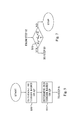
- such boundaries can be vertical boundaries 1, see Fig. 2A , between two neighboring blocks 10, 20 present side by side in the video frame.
- the boundaries are horizontal boundaries 1, see Fig. 2B , between two neighboring block 10, 20, where one block 10 is positioned above the other block 20 in the video frame.
- vertical boundaries are filtered first starting from the left-most boundary and proceeding through the boundaries towards the right-hand side in their geometrical order. Then, horizontal boundaries are filtered starting with the boundary on the top and proceeding through the boundaries towards the bottom in their geometrical order.
- the embodiments are, however, not limited to this particular filtering order and can actually be applied to any predefined filtering order.
- the boundaries at the edge of the video frame are preferably not filtered and thereby excluded from the deblocking filtering.
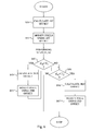
- Fig. 1 is a flow diagram of a method for filtering control applicable to a block of multiple pixels in a video frame according to an embodiment.
- the method of Fig. 1 generally starts in step S1 where a first filter decision value is calculated for the block based at least on
- p 1 i denotes a pixel value of a pixel 13 next closest to, in the first line 12 of pixels 11, 13, 15, 17, the block boundary 1 and p 2 i denotes a pixel value of a pixel 15 second next closest to, in the first line 12 of pixels 11, 13, 15, 17, the block boundary 10.
- Step S2 correspondingly calculates a second filter decision value for the block based at least on
- the first line 12 of pixels 11, 13, 15, 17 in the block 10 and the corresponding first line 22 of pixels 21, 23, 25, 27 in the neighboring block 20 belong to the same horizontal line of pixels, i.e. row of pixels, extending over a vertical boundary 1, see Fig. 2A , or belong to the same vertical line of pixels, i.e. column of pixels, extending over a horizontal boundary 1, see Fig. 2B .
- the first line 12 of pixels 11, 13, 15, 17 and the corresponding first line 22 of pixels 21, 23, 25, 27 are perpendicular to the block boundary 1 between the block 10 and the neighboring block 20.
- the first line 12 of pixels 11, 13, 15, 17 in the block 10 and the corresponding first line 22 of pixels 21, 23, 25, 27 in the neighboring block 20 have the same line number.
- first line 10 of pixels 11, 13, 15, 17 has line number i in the block 10 and the corresponding first line 20 of pixels 21, 23, 25, 27 also has line number i but in the neighboring block 20.
- first line 12 of pixels 11, 13, 15, 17 in the block and the corresponding first line 22 of pixels 21, 23, 25, 27 in the neighboring block 20 are opposing lines with regard to the block boundary 1.
- line of pixels” and “corresponding line of pixels” are employed to denote a "row of pixels” and a “corresponding row of pixels” in the case of a vertical block boundary as in Fig. 2A and denote a "column of pixels” and a “corresponding column of pixels” in the case of a horizontal block boundary as in Fig. 2B .
- the first line 12 of pixels 11, 13, 15, 17 and the corresponding first line 22 of pixels 21, 23, 25, 27 could be predefined lines in the block 10 and the neighboring block 20, respectively.
- the first line 12 of pixels 11, 13, 15, 17 and the corresponding line 22 of pixels 21, 23, 25, 27 have a predefined and fixed line number i with regard to each block boundary 1 for which a filtering control is applied.
- the first line 12 of pixels 11, 13, 15, 17 and the corresponding first line 22 of pixels 21, 23, 25, 27 could represent a current line and a current corresponding line, respectively, which is further discussed herein.
- the calculation of the first filter decision value in step S1 and the calculation of the second filter decision value in step S2 can be performed serially in any order, i.e. step S1 preceding step S2 or step S2 preceding step S1, or at least partly in parallel.
- the results of these two steps S1, S2 is, thus, a first filter decision value that is calculated based on pixel values in the block 10 and a second filter decision value that is calculated based on pixel values in the neighboring block 20 on the other side of the block boundary 1 relative to the block 10. More preferably, the calculation of the first decision value is performed only based on pixel values in the block 10 and therefore not based on any pixel values in the neighboring block 20.
- the second filter decision value is preferably calculated based only on pixel values in the neighboring block 20 and not based on any pixel values in the block 10.
- the first filter decision value calculated in step S1 is then used in step S3 to determine how many pixels in a line 12 of pixels 11, 13, 15, 17 in the block 10 to filter relative to the block boundary 1.
- the second filter decision value is correspondingly used in step S4 to determine how many pixels in a corresponding line 22 of pixels 21, 23, 25, 27 in the neighboring block 20 to filter relative to the block boundary 1.
- the present embodiments instead enable an asymmetric filtering control and deblocking filtering by making a separate filter decision for the line 12 of pixels 11, 13, 15, 17 in the block 10 and another, different filter decision for the corresponding line 22 of pixels 21, 23, 25, 27 in the neighboring block 20.
- pX y denotes the pixel value of pixel number X relative to the block boundary 1 in a line of pixels having line number y in the block 10.
- qX y denotes the pixel value of pixel number X relative to block boundary 1 in a corresponding line of pixels having line number y in the neighboring block 20.
- Steps S3 and S4 can be performed serially in any order or indeed at least partly in parallel.
- steps S1 and S2 could be performed once for a given block boundary 1 between the block 10 and the neighboring block 20 to thereby calculate a first filter decision value and a second filter decision value that applies to all lines 12 of pixels 11, 13, 15, 17 in the block 10 and to all corresponding lines 22 of pixels 21, 23, 25, 27 in the neighboring block 20, respectively.
- the same first number of pixels are preferably filtered and modified in each line 12 of pixels 11, 13, 15, 17 in the block 10 with regard to the block boundary 1, where this first number is determined based on the first filter decision value calculated in step S1.
- the same second number of pixels are preferably filtered and modified in each corresponding line 22 of pixels 21, 23, 25, 27 in the neighboring block 20 with regard to the block boundary 1, where this second number is determined based on the second filter decision value calculated in step S2.
- the first filter decision value and the second filter decision value applies to a subset of the lines 12 of pixels 11, 13, 15, 17 in the block 10 and to a corresponding subset of the corresponding lines 22 of pixels 21, 23, 25, 27 in the neighboring block 20.
- a pair of filter decision values could be used for the first four lines 12 of pixels 11, 13, 15, 17 in the block and the first four corresponding lines 22 of pixels 21, 23, 25, 27 in the neighboring block 20 and with another pair of filter decision values used for the remaining four lines 12 of pixels 11, 13, 15, 17 in the block and the remaining four corresponding lines 22 of pixels 21, 23, 25, 27 in the neighboring block 20.
- step S1 is performed for each line 12 of pixels 11, 13, 15, 17 in the block 10 and a separate determination in step S3 is then performed for each such line 12 of pixels 11, 13, 15, 17.
- step S2 is correspondingly performed for each corresponding line 22 of pixels 21, 23, 25, 27 in the neighboring block 20 and a separate determination in step S4 is performed for each such corresponding line 22 of pixels 21, 23, 25, 27.
- step S3 comprises determining how many pixels in the first line 12 of pixels 11, 13, 15, 17 in the block 10 to filter relative to the block boundary 1 based on the first filter decision value calculated in step S1.
- step S4 comprises determining how many pixels in the corresponding first line 22 of pixels 21, 23, 25, 27 in the neighboring block 20 to filter relative to the block boundary 1 based on the second filter decision value calculated in step S2.
- the third embodiment is applied separately for each line (row or column) crossing the block boundary 1.
- the third embodiment of the method in Fig. 1 can calculate separate first and second filter decision values and therefore make separate determinations of how many pixels to filter for each row or column in the block 10 and the neighboring block 20 relative to the block boundary 1.
- the first and second filter decision values are line-specific filter decision values, i.e. calculated for each line 12 of pixels 11, 13, 15, 17 in the block 10 and for each corresponding line 22 of pixels 21, 23, 25, 27 in the neighboring block 20.
- block-specific filter decision values are used.
- a single first filter decision value could be calculated for the block 10 relative to the block boundary 1 and apply to all lines 12 of pixels 11, 13, 15, 17 in the block 10 with regard to the particular block boundary 1.
- a single second filter decision value is calculated for the neighboring block 20 relative to the block boundary 1 and applies to all corresponding lines 22 of pixels 21, 23, 25, 27 in the neighboring block 20 with regard to the particular block boundary 1.
- a first example of this first embodiment involves calculating a first filter decision value as
- p 0 2 denotes the pixel value of the pixel closest to, in the first line of pixels
- the block boundary 1 denotes the pixel value of the pixel next closest to, in the first line of pixels
- p 2 2 denotes the pixel value of the pixel second next closest to, in the first line of pixels
- the block boundary 1 p 0 5 denotes a pixel value of a pixel closest to, in a second line of pixels in the block 10
- the block boundary 1, p 1 5 denotes a pixel value of a pixel next closest to, in the second line of pixels
- the block boundary 1 and p 2 5 denotes a pixel value of a pixel second next closest to, in the second line of pixels, the block boundary 1.
- the second filter decision value is then preferably calculated as
- the first filter decision value is then used for all lines 12 of pixels 11, 13, 15, 17 in the block 10 when determining how many pixels to filter and the second filter decision value is used for all corresponding line 22 of pixels 21, 23, 25, 27 in the neighboring block 20 when determining how many pixels to filter.
- the first filter decision value could then be calculated as
- a first filter decision value and a second filter decision value are calculated for a group of four lines of pixels and four corresponding lines of pixels.
- This second embodiment can be suitable if the block and the neighboring block each have a size of 4x4 pixels.
- the second embodiment could also be used for larger blocks of pixels, such as 8x8 pixels. In the latter case, a pair of filter decisions is calculated for the first four lines pixels and first four corresponding lines of pixels and another pair of filter decisions is calculated for the remaining four lines of pixels and the remaining four corresponding lines of pixels.
- a first example of the second embodiment calculates the first filter decision value as
- For larger blocks of pixels, such as i 0-7 as shown in Figs.
- the first pair of a first filter decision value and a second filter decision value is calculated as
- the second pair of a first filter decision value and a second filter decision value is then calculated as
- a second example of the second embodiment calculates the first filter decision value as
- For larger blocks of pixels, such as i 0-7 as shown in Figs.
- the first pair of a first filter decision value and a second filter decision value is calculated as
- the second pair of a first filter decision value and a second filter decision value is then calculated as
- the first filter decision value could be calculated as
- the second filter decision value is then preferably calculated as
- the first filter decision value is calculated as ⁇ i
- and the second filter decision value is calculated as ⁇ i
- ⁇ i , ⁇ j represent different line-specific weights. This concept can also be extended to the case with more than two lines of pixels and two corresponding lines of pixels.
- a line of pixels or corresponding line of pixels that is closer to the middle of the block or the neighboring block could then be assigned a comparatively higher weight as compared to a line or pixels or corresponding line of pixels that is closer to one of the edges of the block or the neighboring block.
- a combination of block-specific and line-specific filter decision values is used to determine how many pixels to filter for the lines of pixels in the block and the corresponding lines of pixels in the neighboring block.
- Fig. 3 schematically illustrates such an embodiment.
- the method starts in step S10 where a third filter decision value is calculated as
- the next step S11 calculates a fourth filter decision value as
- Steps S10 and S11 can be performed serially in any order or at least partly in parallel.
- the next step S12 compares the third filter decision value calculated in step S10 with a third threshold value (T 3 ). If the third filter decision value is below the third threshold value the method continues to steps S1 and then S3 of Fig. 1 .
- a respective line-specific or first filter decision value is calculated for each line i in the block 10, where i preferably is from 0 to 7.
- This first filter decision value is then calculated as
- Step S3 of Fig. 1 determines how many pixels in the line i of pixels in the block 10 to filter relative to the block boundary 1 based on the first filter decision value calculated for the line i of pixels in step S1.
- step S13 of Fig. 3 .
- step S13 if the third filter decision value is not below the first threshold value in step S12 the method continues to step S13.
- Step S13 compares the fourth filter decision value calculated in step S11 with a fourth threshold value (T 4 ). If the fourth filter decision value is below the fourth threshold the method continues to steps S2 and S4 of Fig. 1 .
- a respective line-specific or second filter decision value is calculated for each corresponding line i in the neighboring block 20 as
- Step S4 of Fig. 3 determines how many pixels in the corresponding line i of pixels in the neighboring block 20 to filter relative to the block boundary 1 based on the second filter decision value calculated for the corresponding line i of pixels in step S2. This procedure is performed for each corresponding line of pixels in the neighboring block 20. The method then ends. Correspondingly, if the fourth filter decision value is not below the second threshold value in step S13 the method ends.
- steps S12, S1 and S3 can be performed sequentially in any order relative to the loop formed by steps S13, S2 and S4 or at least partly in parallel.
- a combination of block-based and line-based asymmetric filter decisions is used.
- the line-specific filter decision values i.e.
- and d qi
- a third threshold value is used for the third filter decision value
- a first threshold value is used for the first filter decision values
- a fourth threshold value is used for the fourth filter decision value
- a second threshold value is used for the second threshold values.
- the third and fourth threshold values are equal and the first and second threshold values are equal.
- Fig. 4 is a flow diagram illustrating a particular embodiment of the determining steps S3 and S4 of Fig. 1 .
- the method continues from step S2 in Fig. 1 .
- a next step S20 compares the first filter decision value (d p ) calculated in step S1 in Fig. 1 to a first threshold value (T 1 ). If the first filter decision value is below the first threshold value the method continues from step S20 to step S21.
- Step S21 determines to filter two pixels in the line 12 of pixels 11, 13, 15, 17 in the block 10 relative to the block boundary 1. These two pixels are preferably the pixel 11 closest to the block boundary 1 and the pixel 13 next closest to the block boundary 1 in the line 12 of pixels 11, 13, 15, 17.
- step S22 determines to filter one pixel in the line 12 of pixels 11, 13, 15, 17 in the block 10 relative to the block boundary 1. This pixel 11 is preferably the pixel 11 closest to the block boundary 1 in the line 12 of pixels 11, 13, 15, 17.
- step S22 determines to filter no pixels in the line 12 of pixels 11, 13, 15, 17 in the block 10 relative to the block boundary 1.
- Steps S23 to S25 perform the corresponding determination for the corresponding line 22 of pixels 21, 23, 25, 27 in the neighboring block 20.
- step S23 compares the second filter decision value (dq) calculated in step S2 in Fig. 1 with a second threshold value (T 2 ). If the second filter decision value is below the second threshold value the method continues to step S24.
- Step S24 determines to filter two pixels in the corresponding line 22 of pixels 21, 23, 25, 27 in the neighboring block 20 relative to the block boundary 1. These two pixels 21, 23 are preferably the pixel 21 closest to the block boundary 1 and the pixel 23 next closest to the block boundary 1 in the corresponding line 22 of pixels 21, 23, 25, 27. If the second filter decision value is not below the second threshold the method instead continues to step S25 from step S23.
- a first embodiment of step S25 determines to filter one pixel in the corresponding line 22 of pixels 21, 23, 25, 27 in the neighboring block 20 relative to the block boundary 1. This pixel 21 is preferably the pixel 21 closest to the block boundary 1 in the corresponding line 22 of pixels 21, 23, 25, 27.
- a second embodiment of step S25 determines to filter no pixels in the corresponding line 22 of pixels 21, 23, 25, 27 in the neighboring block relative to the block boundary 1.
- Steps S20, S21 and S22 can be performed prior to, following or at least in parallel to steps S23, S24 and S25.
- This concept can be extended by using more than one threshold value per filter decision value. For instance, if d p ⁇ T 1 two pixels are filtered in the line 12 of pixels 11, 13, 15, 17, if T 1 ⁇ d p ⁇ T 1 ' one pixel is filtered in the line 12 of pixels 11, 13, 15, 17 and if d p ⁇ T 1 ' no pixels are filtered in the line 12 of pixels 11, 13,15,17. In this case T 1 ⁇ T 1 '.
- first or second filter decision value in a general aspect the closer the first or second filter decision value is to zero the more filtering is to be applied to the particular line or corresponding line of pixels by filtering and possibly modifying more pixels in the line or corresponding line of pixels as compared to a larger first or second filter decision value.
- a zero or low first or second filter decision value implies no or few structures but rather a fairly uniform area in the video frame.
- a high first or second filter decision value generally reflects local structures in the area in the video frame, which local structures should not be repressed or filtered away.
- This embodiment decreases the computational complexity in connection with deblocking filtering since the filtering of the second pixel from the block border may happen less frequently as compared to the prior art HEVC solution.
- the threshold values discussed in the foregoing and used to compare the different filter decision values are preferably dependent on the quantization parameter (QP) assigned to the block or to the neighboring block.
- Fig. 5 schematically illustrates such an approach.
- the method starts in step S30 where the first threshold value, to which the first filter decision value is compared (see step S20 in Fig. 4 ), is determined based on a quantization parameter associated with the block 10.
- step S31 determines the second threshold value, to which the second threshold value is compared (see step S23 in Fig. 4 ), based on a quantization parameter associated with the neighboring block 20 and/or a quantization parameter associated with the block 10.
- T 1 and T 2 are determined based on the parameter ⁇ , which is determined from the QP value of the block 10 or the neighboring block 20.
- the parameter ⁇ is read from a table based on the QP value, see Table 1 below.
- the above mentioned third and fourth threshold values are preferably determined based on the quantization parameter associated with the block and the neighboring block, respectively.
- Fig. 6 is a flow diagram illustrating how the filtering control of the embodiments can be used in connection with a filtering process.
- the method starts in step S40 where a first offset or delta value ⁇ is calculated based on 9 ⁇ q ⁇ 0 j - p ⁇ 0 j - 3 ⁇ q ⁇ 1 j - p ⁇ 1 j 16 , wherein p 0 j denotes a pixel value of a pixel 11 closest to, in a line 12 of pixels 11, 13, 15, 17, the block boundary 1, p 1 j denotes a pixel value of a pixel 13 next closest to, in the line 12 of pixels 11, 13, 15, 1), the block boundary 1, q 0 j denotes a pixel value of a pixel 21 in the neighboring block 20 closest to, in the corresponding line 22 of pixels 21, 23, 25, 27, the block boundary 1 and q 1 i denotes a pixel value of a pixel 23 of the neighboring block 20 next closest to,
- the method then continues to steps S1 and S2 of Fig. 1 where the first (d p ) and second (d q ) filter decision values are calculated.
- a next step S42 compares the first filter decision value to a first threshold value (T 1 ). This step S42 corresponds to step S20 in Fig. 4 . If the first filter decision value is below the threshold the method continues to step S43.
- Step S43 calculates a second offset or delta value ⁇ p based on p ⁇ 0 j + p ⁇ 2 j - 2 ⁇ p ⁇ 1 j + 2 ⁇ ⁇ 4 , wherein p 2 j denotes a pixel value of a pixel 15 second next closest to, in the line 12 of pixels 11, 13, 15, 17, the block boundary 1.
- step S45 The method then continues to step S45.
- the method also continues in Fig. 6 from step S42 to step S45 if the first threshold value is not below the first threshold.
- Step S45 compares the second filter decision value with a second threshold (T 2 ). This step S45 corresponds to step S23 of Fig. 4 . If the second filter decision value is below the second threshold the method continues to step S46.
- Step S46 calculates a third offset ⁇ q based on q ⁇ 0 j + q ⁇ 2 j - 2 ⁇ q ⁇ 1 j - 2 ⁇ ⁇ 4 , wherein q 2 j denotes a pixel value of a pixel 25 in the neighboring block 20 second next closest to, in the corresponding line 22 of pixels 21, 23, 25, 27, the block boundary 1.
- Steps S42, S43 and S44 can be performed serially in any order or at least partly in parallel with steps S45, S46 and S47.
- the first, second and third offsets are calculated based on particular equations of pixel values.
- the first offset is calculated as a function of 9 ⁇ q ⁇ 0 j - p ⁇ 0 j - 3 ⁇ q ⁇ 1 j - p ⁇ 1 j 16
- the second offset is calculated as a function of p ⁇ 0 j + p ⁇ 2 j - 2 ⁇ p ⁇ 1 j + 2 ⁇ ⁇ 4
- the third offset is calculated as a function of q ⁇ 0 j + q ⁇ 2 j - 2 ⁇ q ⁇ 1 j - 2 ⁇ ⁇ 4 .
- step S40 calculates the first offset to be based on and preferably equal to (9 ⁇ ( q 0 j - p 0 j ) - 3 ⁇ ( q 1 j - p 1 j )+ 8)>>4.
- the modified pixel values as a result of deblocking are calculated like in the following.
- and the second filter decision value is calculated as d q
- Clip3 function is clipping of the output values to the range between the two first function arguments.
- Fig. 7 is a flow diagram illustrating additional optional steps of the method in Fig. 1 .
- the method continues from step S2 in Fig. 1 .
- a next step S50 compares a sum of the first decision value and the second decision value with a threshold value (T). If the sum is not below the threshold value, the method ends. Thus, in such a case no filtering at all is applied to block 10 and neighboring block 20 with regard to the particular block boundary 1.
- the block 10 and the neighboring block 20 then comprises at lot of local structures, which should not be filtered away. However, if the sum is below the threshold value the method continues to steps S3 and S4 in Fig. 1 , where the determination of how many pixels to filter is performed based on the first filter decision value (step S3) or the second filter decision value (step S4).
- This embodiment has an advantage that it does not require many additional computations as the values for the first and second filter decisions are also used for deciding whether to filter the block boundary at all.
- the embodiments disclosed herein achieve asymmetric deblocking decisions that control deblocking filtering to be adaptive to the structure on each side of a block boundary.
- the asymmetric decisions means that the amount of filtering applied to one side of the block boundary can differ from the amount of filtering applied to the other side of the block boundary, thus providing additional adaptation to the local structure. This improves the objective and subjective video quality.
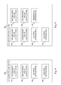
- Fig. 8 is a schematic block diagram of an embodiment of a filtering control device 100.
- the filtering control device 100 comprises a first decision value calculator 110 configured to calculate a first filter decision value for a block 10 in a video frame based at least on
- the filtering control device 100 also comprises a second decision value calculator 120 configured to calculate a second, different filter decision value for the block 10 based on
- a first pixel determiner 130 or first pixel determining unit or processor is configured to determine how many pixels in a line 12 of pixels 11, 13, 15, 17 in the block 10 to filter relative to a block boundary 1 based on the first filter decision value calculated by the first decision value calculator 110.
- a second pixel determiner 140 or second pixel determining unit or processor is provided in the filtering control device 100 to determine how many pixels in a corresponding line 22 of pixel 21, 23, 25, 27 in a neighboring block 20 of the video frame to filter relative to the block boundary based on the second filter decision value calculated by the second decision value calculator 120.
- the first pixel determiner 130 is configured to determine how many pixels in the first line 12 of pixels 11, 13, 15, 17 in the block 10 to filter relative to the block boundary 1 based on the first filter decision value calculated by the first decision value calculator 110 for the first line 12 of pixels 11, 13, 15, 17.
- the second pixel determiner 140 correspondingly determines in this embodiment how many pixels in the corresponding first line 22 of pixels 21, 23, 25, 27 in the neighboring block 20 to filter relative to the block boundary 1 based on the second filter decision value calculated by the second decision value calculator 120 for the corresponding first line 22 of pixels 21, 23, 25, 27.
- the first decision value calculator 110 is configured to calculate the first filter decision value as
- and the second decision value calculator 120 is configured to calculate the second filter decision value as
- the first decision value calculator 110 is configured to calculate the first filter decision value of a first pair as
- and the second decision value calculator 120 is configured to calculate the second filter decision value of the first pair as
- the first filter decision value calculator 110 is also configured to calculate the first filter decision value of a second pair as
- and the second filter decision value calculator 120 is also configured to calculate the second filter decision value of a the second pair as
- Fig. 9 is a schematic block diagram of another embodiment of a filtering control device 100.
- the filtering control device 100 comprises, in this embodiment and in addition to the first decision value calculator 110, the second decision value calculator 120, the first pixel determiner 130 and the second pixel determiner 140, a third decision value calculator 150.
- the third decision value calculator 150 is then configured to calculate a third filter decision value as
- a fourth decision value calculator 160 is also implemented in the filtering control device 100 and configured to calculate a fourth filter decision value as
- the first filter decision value calculator 110 is configured to calculate the first filter decision value if the third filter decision value calculated by the third decision value calculator 150 is below a third threshold value. If the third decision value is below the third threshold, the first decision value calculator 110 calculates a first threshold value for each line i 12 of pixels 11, 13, 15, 17 in the block 10 as
- the first pixel determiner 130 determines, if the third filter decision value is below the third threshold value and for each line i 12 of pixels 11, 13, 15, 17 in the block 10, how many pixels in the line i 12 of pixels 11, 13, 15, 17 in the block 10 to filter relative to the block boundary 1 based on the first filter decision value calculated by the first decision value calculator 110 for the line i 12 of pixels 11, 13, 15, 17.
- the second decision value calculator 120 is preferably responsive to a comparison between the fourth filter decision value and a fourth threshold value. Thus, if the fourth filter decision value calculated by the fourth decision value calculator 160 is below the fourth threshold the second decision value calculator 120 calculates a second filter decision value as
- the second pixel determiner 240 is configured to determine, if the fourth filter decision value is below the fourth threshold value and for each corresponding line i 22 of pixels 21, 23, 25, 27 in the neighboring block 20, how many pixels in the corresponding line i 22 of pixels 21, 23, 25, 27 in the neighboring block 20 to filter relative to the block boundary 1 based on the second filter decision value calculated for the corresponding line i 22 of pixels 21, 23, 25, 27.
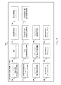
- Fig. 10 is a schematic block diagram of a further embodiment of a filtering control device 100.
- the filtering control device 100 comprises a first comparator 180 configured to compare the first filter decision value calculated by the first decision value calculator 110 to a first threshold value.
- a second comparator 182 is correspondingly configured to compare the second filter decision value calculated by the second decision value calculator 120 to a second threshold value.
- the first pixel determiner 130 is configured to determine to filter two pixels in the line 12 of pixels 11, 13, 15, 17 in the block 10 relative to the block boundary 1 if the first filter decision value is below the first threshold value as determined by the first comparator 180. However, if the first filter decision value is not below the first threshold value the first pixel determiner 130 is instead configured to determine to filter one pixel in the line 12 of pixels 11, 13, 15, 17 in the block 10 relative to the block boundary 1. Alternatively, the first pixel determiner 130 is instead configured to determine to filter no pixels in the line 12 of pixels 11, 13, 15, 17 in the block 10 relative to the block boundary 1.
- the second pixel determiner 140 is configured to determine to filter two pixels in the corresponding line 22 of pixels 21, 23, 25, 27 in the neighboring block 20 relative to the block boundary 1 if the second filter decision value is below the second threshold value as determined by the second comparator 182. However, if the second filter decision value is not below the second threshold the second pixel determiner 140 is instead configured to determine to filter one pixel in the corresponding line 22 of pixels 21, 23, 25, 27 in the neighboring block 20 relative to the block boundary 1. Alternatively, the second pixel determiner 140 is instead configured to determine to filter no pixels in the corresponding line 22 of pixels 21, 23, 25, 27 in the neighboring block 20 relative to the block boundary 1.
- the filtering control device 100 of Fig. 10 comprises a first offset calculator 181 configured to calculate a first offset based on 9 ⁇ q ⁇ 0 j - p ⁇ 0 j - 3 ⁇ q ⁇ 1 j - p ⁇ 1 j 16 ,
- a first pixel modifier 190 of the filtering control device 100 is configured to modify the pixel value of the pixel 11 closest to the block boundary 1 in the line 12 of pixels 11, 13, 15, 17 by adding the first offset to the pixel value of this pixel 11.
- a second pixel value modifier 192 is configured to modify the pixel value of the pixel 21 closest to the block boundary 1 in the corresponding line 12 of pixels 21, 23, 25, 27 by subtracting the first offset from the pixel value of this pixel 21.
- a second offset calculator 183 is preferably implemented in the filtering control device 100 to calculate a second offset if the first filter decision value is below the first threshold value as determined by the first comparator 180. The second offset is then calculated based on p ⁇ 0 j + p ⁇ 2 j - 2 ⁇ p ⁇ 1 j + 2 ⁇ ⁇ 4 .
- a third pixel modifier 194 is operated if the first filter decision value is below the first threshold value. In such a case, the third pixel modifier 194 is configured to modify the pixel value of the pixel 13 next closest to the block boundary 1 in the line 12 of pixels 11, 13, 15, 17 by adding the second offset to the pixel value of this pixel 13.
- a third offset calculator 185 is configured to calculate a third offset based on q ⁇ 0 j + q ⁇ 2 j - 2 ⁇ q ⁇ 1 j - 2 ⁇ ⁇ 4 if the second filter decision value is below the second threshold value as determined by the second comparator 182. If the second filter decision value is below the second threshold value a fourth pixel modifier 196 of the filtering control device 100 is configured to modify the pixel value of the pixel 23 next closest to the block boundary 1 in the corresponding line 22 of pixels 21, 23, 25, 27 by adding the third offset to the pixel value of this pixel 23.
- the embodiments of the filtering control device 100 discussed in the foregoing in connection with Figs. 9 and 10 compares filter decision values to respective threshold values.
- such threshold values are calculated by the filtering control device 100 for the particular block boundary 1.
- the filtering control device 100 then preferably comprises a threshold determiner 170 or threshold determining processor or unit configured to determine the first threshold value used by the first comparator 180 in Fig. 10 and the third threshold value used by the filtering control device 100 in Fig. 9 based on a quantization parameter associated with the block 10.
- the threshold determiner 170 correspondingly preferably determines the second threshold value used by the second comparator 182 in Fig. 10 and the fourth threshold value used by the filtering control device 100 in Fig. 9 based on a quantization parameter associated with the neighboring block 20.
- Fig. 11 is schematic block diagram of yet another embodiment of a filtering control device 100.
- the filtering control device 100 comprises in this embodiment a third comparator 184 configured to compare a sum of the first filter decision value and the second filter decision value to a threshold value. If the sum is equal to or exceeds the threshold value the first and second pixel determiners 130, 140 will not determine any number of pixels to filter since no filtering is to be applied to the block 10 and the neighboring block 20 with regard to the particular block boundary 1. However, if the sum is below the threshold, the first and second pixel determiners 130, 140 are operated to determine the number of pixels to filter based on the first or second filter decision values, respectively.
- the filtering control device 100 discussed in the foregoing and disclosed in Figs. 8-11 can be combined.
- the third value calculator 150 and fourth value calculator 160 of Fig. 9 can be implemented in any of the embodiments disclosed in Figs. 10 or 11 .
- the third comparator 184 of Fig. 11 can be implemented in any of the embodiments disclosed in Figs. 9 or 10 .
- the respective units 110-196 disclosed in conjunction with Figs. 8-11 have been disclosed as physically separate units 110-196 in the filtering control device 100, and all may be special purpose circuits, such as ASICs (Application Specific Integrated Circuits), alternative embodiments of the filtering control device 100 are possible where some or all of the units 110-196 are implemented as computer program modules running on a general purpose processor. Such an embodiment is disclosed in Fig. 12 .
- Fig. 12 schematically illustrates an embodiment of a computer 70 having a processing unit 72, such as a DSP (Digital Signal Processor) or CPU (Central Processing Unit).
- the processing unit 72 can be a single unit or a plurality of units for performing different steps of the method described herein.
- the computer 70 also comprises an input/output (I/O) unit 71 for receiving recorded or generated video frames or encoded video frames and outputting encoded video frame or decoded video data.
- the I/O unit 71 has been illustrated as a single unit in Fig. 12 but can likewise be in the form of a separate input unit and a separate output unit.
- the computer 70 comprises at least one computer program product 73 in the form of a non-volatile memory, for instance an EEPROM (Electrically Erasable Programmable Read-Only Memory), a flash memory or a disk drive.
- the computer program product 73 comprises a computer program 74, which comprises code means which when run on or executed by the computer 70, such as by the processing unit 72, causes the computer 70 to perform the steps of the method described in the foregoing in connection with Fig. 1 .
- the code means in the computer program 74 comprises a first decision value calculating (DVC) module 310 for calculating the first filter decision value for a block, a second pixel value calculating module 320 for calculating the second filter decision value for the block, a first pixel determining (PD) module 330 for determining how many pixels in the line 12 of pixels 11, 13, 15, 17 to filter and a second pixel determining module 340 for determining how many pixels in the corresponding line 22 of pixels 21, 23, 25, 27 to filter.
- DVC decision value calculating
- PD pixel determining
- the computer program 74 may additionally comprise a third decision value calculating module, a fourth decision value calculating module, a threshold determining module, a first comparing module, second comparing module, a third comparing module, a first offset calculating module, a second offset calculating module, a third offset calculating module, a first pixel modifying module, a second pixel modifying module, a third pixel modifying module and/or a fourth pixel modifying module to perform the operation of the corresponding units 150-196 in Figs. 9-11 .
- the computer 70 of Fig. 12 can be a user equipment or be present in a user equipment.
- the user equipment may additionally comprise or be connected to a display to display video data.
- the filtering control device of Figs. 8-11 is preferably used in video coding. It functions and is therefore preferably implemented both in a video encoder and in a video decoder.
- the video decoder can be implemented preferably in hardware but also in software. The same holds for the video encoder.
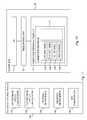
- Fig. 13 is a schematic block diagram of an encoder 40 for encoding a block of pixels in a video frame of a video sequence according to an embodiment.
- a current block of pixels is predicted by performing a motion estimation by a motion estimator 50 from an already provided block of pixels in the same frame or in a previous frame.
- the result of the motion estimation is a motion or displacement vector associated with the reference block, in the case of inter prediction.
- the motion vector is utilized by a motion compensator 50 for outputting an inter prediction of the block of pixels.
- An intra predictor 49 computes an intra prediction of the current block of pixels.
- the outputs from the motion estimator/compensator 50 and the intra predictor 49 are input in a selector 51 that either selects intra prediction or inter prediction for the current block of pixels.
- the output from the selector 51 is input to an error calculator in the form of an adder 41 that also receives the pixel values of the current block of pixels.
- the adder 41 calculates and outputs a residual error as the difference in pixel values between the block of pixels and its prediction.
- the error is transformed in a transformer 42, such as by a discrete cosine transform, and quantized by a quantizer 43 followed by coding in an encoder 44, such as by entropy encoder.
- a transformer 42 such as by a discrete cosine transform
- a quantizer 43 quantized by a quantizer 43
- an encoder 44 such as by entropy encoder.
- the estimated motion vector is brought to the encoder 44 for generating the coded representation of the current block of pixels.
- the transformed and quantized residual error for the current block of pixels is also provided to a inverse quantizer 45 and inverse transformer 46 to retrieve the original residual error.
- This error is added by an adder 47 to the block prediction output from the motion compensator 50 or the intra predictor 49 to create a reference block of pixels that can be used in the prediction and coding of a next block of pixels.
- This new reference block is first processed by a filtering control device 100 according to the embodiments in order to control any deblocking filtering that is applied to the reference block to combat any blocking artifact.
- the processed new reference block is then temporarily stored in a frame buffer 48, where it is available to the intra predictor 49 and the motion estimator/compensator 50.
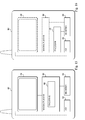
- Fig. 14 is a corresponding schematic block diagram of a decoder 60 comprising a filtering control device 100 according to the embodiments.
- the decoder 60 comprises a decoder 61, such as entropy decoder, for decoding an encoded representation of a block of pixels to get a set of quantized and transformed residual errors. These residual errors are dequantized in an inverse quantizer 62 and inverse transformed by an inverse transformer 63 to get a set of residual errors.
- the reference block is determined by a motion estimator/compensator 67 or intra predictor 66, depending on whether inter or intra prediction is performed.
- a selector 68 is thereby interconnected to the adder 64 and the motion estimator/compensator 67 and the intra predictor 66.
- the resulting decoded block of pixels output form the adder 64 is input to a filtering control device 100 according to the embodiments in order to control any deblocking filter that is applied to combat any blocking artifacts.
- the filtered block of pixels is output form the decoder 60 and is furthermore preferably temporarily provided to a frame buffer 65 and can be used as a reference block of pixels for a subsequent block of pixels to be decoded.
- the frame buffer 65 is thereby connected to the motion estimator/compensator 67 to make the stored blocks of pixels available to the motion estimator/compensator 67.
- the output from the adder 64 is preferably also input to the intra predictor 66 to be used as an unfiltered reference block of pixels.
- the filtering control device 100 controls deblocking filtering in the form of so called in-loop filtering.
- the filtering control device 100 is arranged to perform so called post-processing filtering.
- the filtering control device 100 operates on the output frames outside of the loop formed by the adder 64, the frame buffer 65, the intra predictor 66, the motion estimator/compensator 67 and the selector 68. No deblocking filtering and filtering control is then typically done at the encoder.
- Fig. 15 is a schematic block diagram of a user equipment or media terminal 80 housing a decoder 60 with a filtering control device.
- the user equipment 80 can be any device having media decoding functions that operates on an encoded video stream of encoded video frames to thereby decode the video frames and make the video data available. Non-limiting examples of such devices include mobile telephones and other portable media players, tablets, desktops, notebooks, personal video recorders, multimedia players, video streaming servers, set-top boxes, TVs, computers, decoders, game consoles, etc.
- the user equipment 80 comprises a memory 84 configured to store encoded video frames. These encoded video frames can have been generated by the user equipment 80 itself. Alternatively, the encoded video frames are generated by some other device and wirelessly transmitted or transmitted by wire to the user equipment 80.
- the user equipment 80 then comprises a transceiver (transmitter and receiver) or input and output port 82 to achieve the data transfer.
- the encoded video frames are brought from the memory 84 to a decoder 60, such as the decoder illustrated in Fig. 14 .
- the decoder 60 comprises a filtering control device 100 according to embodiments.
- the decoder 60 then decodes the encoded video frames into decoded video frames.
- the decoded video frames are provided to a media player 86 that is configured to render the decoded video frames into video data that is displayable on a display or screen 88 of or connected to the user equipment 80.
- the user equipment 80 has been illustrated as comprising both the decoder 60 and the media player 86, with the decoder 60 implemented as a part of the media player 86.
- Also distributed implementations are possible where the decoder 60 and the media player 86 are provided in two physically separated devices are possible and within the scope of user equipment 80 as used herein.
- the display 88 could also be provided as a separate device connected to the user equipment 80, where the actual data processing is taking place.
- Fig. 16 illustrates another embodiment of a user equipment 80 that comprises en encoder, such as the encoder of Fig. 13 , comprising a filtering control device according to the embodiments.
- the encoder 40 is then configured to encode video frames received by the I/O unit 82 and/or generated by the user equipment 80 itself.
- the user equipment 80 preferably comprises a media engine or recorder, such as in the form of or connected to a (video) camera.
- the user equipment 80 may optionally also comprise a media player 86, such as a media player 86 with a decoder and filtering control device according to the embodiments, and a display 88.
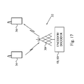
- the encoder 40 and/or decoder 60 may be implemented in a network device 30 being or belonging to a network node in a communication network 32 between a sending unit 34 and a receiving user equipment 36.
- a network device 30 may be a device for converting video according to one video coding standard to another video coding standard, for example, if it has been established that the receiving user equipment 36 is only capable of or prefers another video coding standard than the one sent from the sending unit 34.
- the network device 30 can be in the form of or comprised in a radio base station, a Node-B or any other network node in a communication network 32, such as a radio-based network.
Description
- The present embodiments generally relate to filtering control and in particular to controlling deblocking filtering over block boundaries in a video frame.
- Deblocking filters are used in the video coding standards in order to combat blocking artifacts. The blocking artifacts arise because the original video frames are split into blocks which are processed relatively independently. The blocking artifacts can, for instance, arise due to different intra predictions of the blocks, quantization effects and motion compensation. Two particular variants of deblocking are described below.
- In state of the art video coding, such as H.264, there is a deblocking filter, also denoted loop filter, after prediction and residual reconstruction, but before storage of the reconstruction for later reference when encoding or decoding the subsequent frames. The deblocking filtering consists of several steps such as filter decisions, filtering operations, a clipping function and changes of pixel values. The decision to filter the border or not is made based on evaluation of several conditions. Filter decisions depend on macroblock (MB) type, motion vector (MV) difference between neighboring blocks, whether neighboring blocks have coded residuals and on the local structure of the current and/or neighboring blocks.
- Then the amount of filtering for a pixel depends, among others, on the position of that pixel relative to the block border or boundary and on the quantization parameter (QP) value used for residual coding.
- The filter decision is based on comparing three pixel differences with thresholds. The thresholds are adapted to the quantization parameter (QP). For instance, assume a vertical block boundary of
- a b c d | e f g h
- There are two filtering modes in H.264. In the first filtering mode, referred to as normal filtering, filtering can be described with a delta value with which filtering changes the current value. The filtering for the pixels closest to the block boundary is d' = d + delta and e' = e - delta, where delta has been clipped off to a threshold ±thr3 to a value that is constrained by the QP. More filtering is thereby allowed for high QP than for low QP. Clipping can be described as delta_clipped = max(-thr3, min(thr3, delta)), where thr3 is controlling the filter strength. A larger value of thr3 means that the filtering is stronger which means that a stronger low-pass filtering effect will happen.
- The filter strength can be increased if any of the following two conditions also holds, e.g. abs(b-d)<thr2 and abs(e-g)<thr2. The filter strength is adapted by clipping the delta less, e.g. allow for more variation.
- The second filtering mode, referred to as strong filtering, is applied for intra macroblock boundaries only, when the following condition is fulfilled abs(d-e)< thr1/4.
- For more information of deblocking filtering in H.264 reference is made to List et al., Adaptive Deblocking Filter, IEEE Transactions on Circuits and Systems for Video Technology, vol. 13, no. 7, July 2003.
- In the draft HEVC (High Efficiency Video Coding) specification "Test Model under Consideration", ITU-T SG16 WP3 document, JCTVC-B205, Chapter 6.5 In-loop filter process, the deblocking filter works differently from H.264. The filtering is performed if at least one of the blocks on the side of the boundary is intra, or has non-zero coefficients, or the difference between the motion vector components of the blocks is greater or equal to one integer pixel. For example, when filtering the border between the blocks with a vertical block boundary of

with pji denoting the pixel value of pixel number j of row number i in the current block and qji denoting the pixel value of pixel number j of row number i in the neighboring block, i=0...7, j=0...3, then the following condition should also be satisfied:
- where β depends on QP. In the above mentioned HEVC specification, there is a table of β, where β increases with QP.
- If the conditions are fulfilled and filtering is done between the current block and the neighboring block, one of two types of filtering is performed, referred to as weak and strong filtering, respectively. The choice between the strong and the weak filtering is done separately for each line depending on the following conditions. For each line i=0...7, the strong filtering is performed if all the following conditions are true, otherwise, weak filtering is performed:


where tc and β depend on QP and >> denotes a right shift operator. - Weak filtering is performed based on the above conditions. The actual filtering works by computing an offset (Δ), adding it to the original pixel value and clip the sum to a filtered output pixel value in the range of 0-255:


where the clip function Clip(A, B, x) is defined as Clip(A, B, x)=A if x<A, Clip(A, B, x)=B if x>B and Clip(A, B, x)=x if A≤x≤B and Clip0-255(X) is defined as Clip(0, 255, x). - Strong filtering mode is performed by the following set of operations:


- Deblocking filtering decisions according to HEVC can lead to inaccurate deblocking filtering over block boundaries for certain blocks. In particular neighboring blocks having different levels of local structures could be handled incorrectly in HEVC by filtering one of the blocks too much to thereby represses and filter away local structures in the block.
- Matthias Narroschke et al: Reduction of operations in the critical path of the deblocking filter", 95, MPEG meeting 24-1-2011-28-1-2011; Dagu; no. m18974, 22 January 2011 relates to a method for determining filter decisions. Pixels on both sides of the block boundary are used for determining one filtering decision, i.e. how many pixels that should be considered for deblocking, but the same filter decision is used for both sides of the block boundary.
-
US 2010/142844 A1 relates to a deblocking operation wherein a region of interest is determined which determines the number of pixels that should be filtered. The number of pixels can be different on either side of the block boundary. The region of interest is determined based on N0 (for block B0) and N1 (for block B1) which are calculated based on an activity metric and an artifact count. The artifact count is determined for each block and an activity is determined for each row and for each column of each block. When determining the artifact count for N0 pixels on both side of the block boundary are used, and also when determining the artifact count for N1 pixels on both side of the block boundary are used. - Hence, there is a need for an efficient deblocking filtering control that can be used to reduce blocking artifacts at block boundaries and that does not have the above mentioned drawbacks. It is a general objective to provide an efficient deblocking filtering control. It is a particular objective to provide asymmetric filtering decisions over a block boundary.
- According to a first aspect a method for filtering control applicable to a block of multiple pixels in a video frame is provided where each pixel has a respective pixel value. In the method, a first filter decision value for said block is calculated, by only using pixels of said block, based on:

wherein i=0...N-1 and N is the number of lines of pixels of said block, a line of pixels being a row or a column of pixels, wherein p0 i denotes a pixel value of a pixel closest to, in a first line of pixels in said block, a block boundary to a neighboring block of multiple pixels in said video frame. p1 i denotes a pixel value of a pixel next closest to, in said first line of pixels, said block boundary and p2 i denotes a pixel value of a pixel second next closest to, in said first line of pixels, said block boundary. A second filter decision value for said neighboring block is calculated, by only using pixels of said neighboring block based on:
wherein i=0...N-1 and N is the number of lines of pixels of said neighboring block, a line of pixels being a row or a column of pixels, wherein q0 i denotes a pixel value of a pixel in said neighboring block closest to, in a corresponding first line of pixels in said neighboring block, said block boundary. q1 i denotes a pixel value of a pixel of said neighboring block next closest to, in said corresponding first line of pixels, said block boundary and q2 i denotes a pixel value of a pixel in said neighboring block second next closest to, in said corresponding first line of pixels, said block boundary. The first line of pixels and the corresponding first line in the neighboring block are opposing lines with regard to the block boundary and perpendicular to the block boundary. It is determined how many pixels in said first line of pixels in said block to filter relative to said block boundary based on a comparison of said first filter decision value to a first threshold value and how many pixels in said corresponding first line of pixels in said neighboring block to filter relative to said block boundary based on a comparison of said second filter decision value to a second threshold value. - According to a second aspect a filtering control device is provided. The filtering control device comprises a first decision value calculator configured to calculate a first filter decision value for a block of multiple pixels in a video frame, by only using pixels of said block, based on:

wherein i=0...N-1 and N is the number of lines of pixels of said block and a line of pixels being a row or a column of pixels. p0 i denotes a pixel value of a pixel closest to, in a first line of pixels in said block, a block boundary to a neighboring block of multiple pixels in said video frame, p1 i denotes a pixel value of a pixel next closest to, in said first line of pixels, said block boundary and p2 i denotes a pixel value of a pixel second next closest to, in said first line of pixels, said block boundary. The filtering control device further comprises a second decision value calculator configured to calculate a second filter decision value for a neighboring block, by only using pixels of said neighboring block, based on:
wherein i=0---N-1 and N is the number of lines of pixels of said neighboring block (20), a line of pixels being a row or a column of pixels. q0 i denotes a pixel value of a pixel in said neighboring block closest to, in a corresponding first line of pixels in said neighboring block, said block boundary, q1 i denotes a pixel value of a pixel of said neighboring block next closest to, in said corresponding first line of pixels, and said block boundary and q2 i denotes a pixel value of a pixel in said neighboring block second next closest to, in said corresponding first line of pixels, said block boundary. The first line of pixels and the corresponding first line in the neighboring block are opposing lines with regard to the block boundary and perpendicular to the block boundary. The filtering control device further comprises a first pixel determiner configured to determine how many pixels in a first line of pixels in said block to filter relative to said block boundary based on said first filter decision value calculated by said first decision value calculator and a second pixel determiner configured to determine how many pixels in a corresponding first line of pixels in said neighboring block to filter relative to said block boundary based on said second filter decision value calculated by said second decision value calculator. The filtering control device further comprises a first comparator configured to compare said first filter decision value calculated by said first decision value calculator to a first threshold value and a second comparator configured to compare said second filter decision value calculated by said second decision value calculator to a second threshold value. - According to a further aspect an encoder comprising a filtering control device according to the aspect above is provided.
- According to a yet further aspect a user equipment is provided. The user equipment comprises a memory configured to store video frames, and an encoder according to the aspect above configured to encode said video frames into encoded video frames, wherein said memory is further configured to store said encoded video frames.
- According to a yet further aspect a decoder is provided which comprises a filtering control device according to the aspect above.
- According to a yet further aspect a user equipment is provided which comprises a memory configured to store encoded video frames, a decoder according to an aspect above configured to decode said encoded video frames into decoded video frames, and a media player configured to render said decoded video frames into video data displayable on a display.
- According to a yet further aspect a computer program for filtering control of a block of multiple pixels in a video frame is provided where each pixel having a respective pixel value. Said computer program comprises code means which when run on a computer causes the computer to calculate a first filter decision value for said block, by only using pixels of said block, based on:

wherein i=0...N-1 and N is the number of lines of pixels of said block (10), a line of pixels being a row or a column of pixels. p0 i denotes a pixel value of a pixel closest to, in a first line of pixels in said block, a block boundary to a neighboring block of multiple pixels in said video frame, p1 i denotes a pixel value of a pixel next closest to, in said first line of pixels, said block boundary and p2 i denotes a pixel value of a pixel second next closest to, in said first line of pixels, said block boundary. The computer is further caused to calculate a second filter decision value for said neighboring block, by only using pixels of said neighboring block, based on:
wherein i=0---N-1 and N is the number of lines of pixels of said neighboring block, a line of pixels being a row or a column of pixels. q0 i denotes a pixel value of a pixel in said neighboring block closest to, in a corresponding first line of pixels in said neighboring block, said block boundary, q1 i denotes a pixel value of a pixel of said neighboring block next closest to, in said corresponding first line of pixels, said block boundary and q2 i denotes a pixel value of a pixel in said neighboring block second next closest to, in said corresponding first line of pixels, said block boundary. The first line of pixels and the corresponding first line in the neighboring block are opposing lines with regard to the block boundary and perpendicular to the block boundary. The computer is further caused to determine how many pixels in a first line of pixels in said block to filer relative to said block boundary based on said first filter decision value and to determine how many pixels in a corresponding first line of pixels in said neighboring block to filter relative to said block boundary based on said second filter decision value,
wherein determine how many pixels in said first line of pixels in said block to filter comprises determining how many pixels in said first line of pixels in said block to filter relative to said block boundary based on a comparison of said first filter decision value to a first threshold value and to determine how many pixels in said corresponding first line of pixels in said neighboring block to filter comprises determining how many pixels in said corresponding first line of pixels in said neighboring block to filter relative to said block boundary based on a comparison of said second filter decision value to a second threshold value. - The embodiments achieve asymmetric deblocking decisions that control deblocking filtering to be adaptive to the structure on each side of a block boundary. The asymmetric decisions means that the amount of filtering applied to one side of the block boundary can differ from the amount of filtering applied to the other side of the block boundary, thus providing additional adaptation to the local structure. This improves the objective and subjective video quality.
- The invention, together with further objects and advantages thereof, may best be understood by making reference to the following description taken together with the accompanying drawings, in which:
-
Fig. 1 is a flow diagram of a method for filtering control according to an embodiment; -
Figs. 2A and 2B illustrate two embodiments of neighboring blocks and a block boundary over which deblocking filtering can be applied; -
Fig. 3 is a flow diagram illustrating additional, optional steps of the method inFig. 1 according to an embodiment; -
Fig. 4 is a flow diagram illustrating an embodiment of the determining steps inFig. 1 ; -
Fig. 5 is a flow diagram illustrating additional, optional steps of the method inFig. 1 according to another embodiment; -
Fig. 6 is a flow diagram illustrating additional, optional steps of the method inFig. 1 and an embodiment of the determining steps inFig. 1 ; -
Fig. 7 is a flow diagram illustrating an additional, optional step of the method inFig. 1 according to an embodiment; -
Fig. 8 is a schematic block diagram of an embodiment of a filtering control device; -
Fig. 9 is a schematic block diagram of another embodiment of a filtering control device; -
Fig. 10 is a schematic block diagram of a further embodiment of a filtering control device; -
Fig. 11 is a schematic block diagram of yet another embodiment of a filtering control device; -
Fig. 12 is a schematic block diagram of a software implementation of a filtering control device in a computer according to an embodiment; -
Fig. 13 is a schematic block diagram of an encoder according to an embodiment; -
Fig. 14 is a schematic block diagram of a decoder according to an embodiment; -
Fig. 15 is a schematic block diagram of a user equipment according to an embodiment; -
Fig. 16 is a schematic block diagram of a user equipment according to another embodiment; and -
Fig. 17 is a schematic overview of a portion of a communication network comprising a network device according to an embodiment. - Throughout the drawings, the same reference numbers are used for similar or corresponding elements.
- The embodiments generally relate to filtering control and controlling deblocking filtering over block boundaries in a video frame. The filtering control of the embodiments provides asymmetric deblocking decisions with regard to block boundaries by making independent filtering decisions for the blocks of pixels separated by a block boundary. This means that the deblocking filtering can handle neighboring blocks having different levels of local structures to thereby adapt the particular deblocking filtering at each block based on its local structures.
- As is well-known in the art, a video frame is divided into non-overlapping blocks of pixels that are encoded and decoded according to the various available intra and inter coding modes. Generally, a video frame is divided into non-overlapping macroblocks of 16x16 pixels. Such a macroblock can in turn be divided into smaller blocks of different sizes, such as 4x4 or 8x8 pixels. However, also rectangular blocks are possible according to the embodiments, such as, 4x8, 8x4, 8x16 or 16x8. The embodiments can be applied to any such block of pixels, including macroblocks or even larger blocks of pixels.
- In the emerging High Efficiency Video Coding (HEVC) standard, coding units (CU), prediction units (PU) and transform units (TU) are used. The prediction units are defined inside a coding unit and contain the intra or inter prediction modes. Transform units are defined inside a coding unit and the largest transform size is 32×32 pixels and the smallest size is 4×4 pixels. The CU size is currently varying from 64×64 pixels (largest) to 8×8 pixels (smallest). In this way, the largest CU can be split into smaller CUs with the "level of granularity" depending on the local characteristics of the frame. That means that the largest CU may be split into smaller CUs of different sizes. The embodiments can also be used in connection with such coding units, which are regarded as being encompassed by the expression "block of pixels" as used herein.
- Each pixel in the block has a respective pixel value. Video frames generally have color values assigned to the pixels, where the color values are represented in a defined color formats. One of the common color formats uses one luminance component and two chrominance components for each pixel, although other formats exist, such as using red, green and blue components for each pixel.
- Traditionally, luminance component filtering and chrominance component filtering are done separately, possibly employing different filtering decisions and different deblocking filters. It is, though, possible that the luminance filtering decisions are used in chroma filtering, like in H.264. The embodiments can be applied to filtering control for the luminance component, the chrominance component or both the luminance component and the chrominance component. In a particular embodiment, the embodiments are applied to control luminance or luma filtering. Filtering decisions, or parts of filtering decisions for one component, such as luma, can be then used when making the filtering decisions for other components, such as chroma.
- Deblocking filtering is conducted over a boundary, edge or border between neighboring blocks. As a consequence, such boundaries can be
vertical boundaries 1, seeFig. 2A , between two neighboringblocks horizontal boundaries 1, seeFig. 2B , between two neighboringblock block 10 is positioned above theother block 20 in the video frame. In a particular embodiment, vertical boundaries are filtered first starting from the left-most boundary and proceeding through the boundaries towards the right-hand side in their geometrical order. Then, horizontal boundaries are filtered starting with the boundary on the top and proceeding through the boundaries towards the bottom in their geometrical order. The embodiments are, however, not limited to this particular filtering order and can actually be applied to any predefined filtering order. In a particular embodiment, the boundaries at the edge of the video frame are preferably not filtered and thereby excluded from the deblocking filtering. -
Fig. 1 is a flow diagram of a method for filtering control applicable to a block of multiple pixels in a video frame according to an embodiment. The method ofFig. 1 generally starts in step S1 where a first filter decision value is calculated for the block based at least on |p2 i - 2p1 i + p0 i | wherein p0 i denotes a pixel value of apixel 11 closest to, in a first line ofpixels block 10, ablock boundary 1 to a neighboringblock 20 ofmultiple pixels pixel 13 next closest to, in thefirst line 12 ofpixels block boundary 1 and p2 i denotes a pixel value of apixel 15 second next closest to, in thefirst line 12 ofpixels block boundary 10. - Step S2 correspondingly calculates a second filter decision value for the block based at least on |q2i - 2q1 i + q0i |, wherein q0 i denotes a pixel value of a
pixel 21 in the neighboringblock 20 closest to, in a correspondingfirst line 22 ofpixels block 20, theblock boundary 1, q1 i denotes a pixel value of apixel 23 of the neighboringblock 20 next closest to, in the correspondingfirst line 22 ofpixels block boundary 1 and q2i denotes a pixel value of apixel 25 in the neighboringblock 20 second next closest to, in the correspondingfirst line 22 ofpixels block boundary 1. - The
first line 12 ofpixels block 10 and the correspondingfirst line 22 ofpixels block 20 belong to the same horizontal line of pixels, i.e. row of pixels, extending over avertical boundary 1, seeFig. 2A , or belong to the same vertical line of pixels, i.e. column of pixels, extending over ahorizontal boundary 1, seeFig. 2B . Hence, thefirst line 12 ofpixels first line 22 ofpixels block boundary 1 between theblock 10 and the neighboringblock 20. Furthermore, thefirst line 12 ofpixels block 10 and the correspondingfirst line 22 ofpixels block 20 have the same line number. For instance, if theblock 10 and the neighboringblock 20 each comprises N, such as eight, rows or columns of pixels, having row or column numbers i=0...N-1 then thefirst line 10 ofpixels block 10 and the correspondingfirst line 20 ofpixels block 20. Thus,first line 12 ofpixels first line 22 ofpixels block 20 are opposing lines with regard to theblock boundary 1. - According to the embodiments, "line of pixels" and "corresponding line of pixels" are employed to denote a "row of pixels" and a "corresponding row of pixels" in the case of a vertical block boundary as in
Fig. 2A and denote a "column of pixels" and a "corresponding column of pixels" in the case of a horizontal block boundary as inFig. 2B . - The
first line 12 ofpixels first line 22 ofpixels block 10 and the neighboringblock 20, respectively. Thus, thefirst line 12 ofpixels corresponding line 22 ofpixels block boundary 1 for which a filtering control is applied. Alternatively, thefirst line 12 ofpixels first line 22 ofpixels - The calculation of the first filter decision value in step S1 and the calculation of the second filter decision value in step S2 can be performed serially in any order, i.e. step S1 preceding step S2 or step S2 preceding step S1, or at least partly in parallel. The results of these two steps S1, S2 is, thus, a first filter decision value that is calculated based on pixel values in the
block 10 and a second filter decision value that is calculated based on pixel values in the neighboringblock 20 on the other side of theblock boundary 1 relative to theblock 10. More preferably, the calculation of the first decision value is performed only based on pixel values in theblock 10 and therefore not based on any pixel values in the neighboringblock 20. Correspondingly, the second filter decision value is preferably calculated based only on pixel values in the neighboringblock 20 and not based on any pixel values in theblock 10. - The first filter decision value calculated in step S1 is then used in step S3 to determine how many pixels in a
line 12 ofpixels block 10 to filter relative to theblock boundary 1. The second filter decision value is correspondingly used in step S4 to determine how many pixels in acorresponding line 22 ofpixels block 20 to filter relative to theblock boundary 1. Thus, separate filter decision values are calculated for each side or part of a row or column of pixels extending over theblock boundary 1 and a respective filter decision is taken for each side or part based on the particular filter decision value calculated for that side or part. - This should be compared to the prior art where a single or a set of filter decision values is calculated for a line of pixels and the corresponding line of pixels and where this filter decision value or set of filter decision values is used to decide how many pixels to filter on both sides of the block boundary. Thus, in the prior art the same number of pixels is always filtered for the corresponding line of pixels in the neighboring block as is done for the matching line of pixels in the block.
- The present embodiments instead enable an asymmetric filtering control and deblocking filtering by making a separate filter decision for the
line 12 ofpixels block 10 and another, different filter decision for thecorresponding line 22 ofpixels block 20. This means that based on the particular first and second filter decision values different or the same number of pixels in theline 12 ofpixels corresponding line 22 ofpixels - Generally, herein pXy denotes the pixel value of pixel number X relative to the
block boundary 1 in a line of pixels having line number y in theblock 10. Correspondingly, qXy denotes the pixel value of pixel number X relative to blockboundary 1 in a corresponding line of pixels having line number y in the neighboringblock 20. - Steps S3 and S4 can be performed serially in any order or indeed at least partly in parallel.
- In a first embodiment, steps S1 and S2 could be performed once for a given
block boundary 1 between theblock 10 and the neighboringblock 20 to thereby calculate a first filter decision value and a second filter decision value that applies to alllines 12 ofpixels block 10 and to all correspondinglines 22 ofpixels block 20, respectively. In such approach the same first number of pixels are preferably filtered and modified in eachline 12 ofpixels block 10 with regard to theblock boundary 1, where this first number is determined based on the first filter decision value calculated in step S1. Correspondingly, the same second number of pixels are preferably filtered and modified in eachcorresponding line 22 ofpixels block 20 with regard to theblock boundary 1, where this second number is determined based on the second filter decision value calculated in step S2. - Alternatively, in a second embodiment the first filter decision value and the second filter decision value applies to a subset of the
lines 12 ofpixels block 10 and to a corresponding subset of thecorresponding lines 22 ofpixels block 20. For instance, a pair of filter decision values could be used for the first fourlines 12 ofpixels lines 22 ofpixels block 20 and with another pair of filter decision values used for the remaining fourlines 12 ofpixels corresponding lines 22 ofpixels block 20. - In a third embodiment the calculation in step S1 is performed for each
line 12 ofpixels block 10 and a separate determination in step S3 is then performed for eachsuch line 12 ofpixels corresponding line 22 ofpixels block 20 and a separate determination in step S4 is performed for each suchcorresponding line 22 ofpixels - Thus, in the third embodiment step S3 comprises determining how many pixels in the
first line 12 ofpixels block 10 to filter relative to theblock boundary 1 based on the first filter decision value calculated in step S1. Step S4 comprises determining how many pixels in the correspondingfirst line 22 ofpixels block 20 to filter relative to theblock boundary 1 based on the second filter decision value calculated in step S2. - The following part describes how the third embodiment is applied separately for each line (row or column) crossing the
block boundary 1. In this example the first filter decision value is defined as dpi = |p2 i - 2p1 i + p0 i | and the second filter decision value is defined as dqi = |q2 i - 2q1 i + q0 i |. The method then comprises: - Calculate dpi, calculate dqi for each line i crossing the block boundary.
- if dpi < thr1
- ∘ do normal filtering of line i of
current block 10, e.g. filter and modify two pixels from the block border or boundary;
- ∘ do normal filtering of line i of
- else, i.e. if dpi ≥ thr1
- ∘ do not filter the second pixel from the block border or boundary of line i of the
current block 10 or do not filter any pixels at all on line i of thecurrent block 10;
- ∘ do not filter the second pixel from the block border or boundary of line i of the
- if dqi < thr2
- ∘ do normal filtering of line i of neighboring
block 20, e.g. filter and modify two pixels from the block border orboundary 1;
- ∘ do normal filtering of line i of neighboring
- else, i.e. if dqi ≥ thr2
- ∘ do not filter the second pixel from the block border or
boundary 1 of line i of the neighboringblock 20 or do not filter any pixels at all on line i of the neighboringblock 20.
- ∘ do not filter the second pixel from the block border or
- As is illustrated by the example above, the third embodiment of the method in
Fig. 1 can calculate separate first and second filter decision values and therefore make separate determinations of how many pixels to filter for each row or column in theblock 10 and the neighboringblock 20 relative to theblock boundary 1. Thus, in this third embodiment the first and second filter decision values are line-specific filter decision values, i.e. calculated for eachline 12 ofpixels block 10 and for eachcorresponding line 22 ofpixels block 20. - In the first embodiment, block-specific filter decision values are used. Thus, in such a case a single first filter decision value could be calculated for the
block 10 relative to theblock boundary 1 and apply to alllines 12 ofpixels block 10 with regard to theparticular block boundary 1. Correspondingly a single second filter decision value is calculated for the neighboringblock 20 relative to theblock boundary 1 and applies to all correspondinglines 22 ofpixels block 20 with regard to theparticular block boundary 1. - A first example of this first embodiment involves calculating a first filter decision value as |p22 - 2p12 + p02| + |p25 - 2p15 + p05|, wherein p02 denotes the pixel value of the pixel closest to, in the first line of pixels, the
block boundary 1, p12 denotes the pixel value of the pixel next closest to, in the first line of pixels, theblock boundary 1, p22 denotes the pixel value of the pixel second next closest to, in the first line of pixels, theblock boundary 1, p05 denotes a pixel value of a pixel closest to, in a second line of pixels in theblock 10, theblock boundary 1, p15 denotes a pixel value of a pixel next closest to, in the second line of pixels, theblock boundary 1 and p25 denotes a pixel value of a pixel second next closest to, in the second line of pixels, theblock boundary 1. - The second filter decision value is then preferably calculated as |q22 - 2q12 + q02| + |q25 - 2q15 + q05|, wherein q02 denotes the pixel value of the pixel in the neighboring
block 20 closest to, in the corresponding first line of pixels, theblock boundary 1, q12 denotes the pixel value of the pixel of the neighboringblock 20 next closest to, in the corresponding first line of pixels, theblock boundary 1, q22 denotes the pixel value of the pixel in the neighboringblock 20 second next closest to, in the corresponding first line of pixels, theblock boundary 1, q05 denotes a pixel value of a pixel in the neighboringblock 20 closest to, in a corresponding second line of pixels in the neighboringblock 20, theblock boundary 1, q15 denotes a pixel value of a pixel of the neighboringblock 20 next closest to, in the corresponding second line of pixels, theblock boundary 1 and q25 denotes a pixel value of a pixel in the neighboringblock 20 second next closest to, in the corresponding second line of pixels, theblock boundary 1. - The first filter decision value is then used for all
lines 12 ofpixels block 10 when determining how many pixels to filter and the second filter decision value is used for all correspondingline 22 ofpixels block 20 when determining how many pixels to filter. - In this first example of the first embodiment, the first line of pixels corresponds to line i=2 and the corresponding first line corresponds to corresponding line i=2 and the second line of pixels corresponds to line i=5 and the second corresponding line corresponds to corresponding line i=5. In this case the
block 10 preferably comprises eight lines and the neighboringblock 20 preferably also comprises eight lines, i.e. i=0-7. - The following part illustrates an implementation example of the first embodiment. In this implementation example the first filter decision value is defined as dp = |p22 - 2p12 + p02| + p25 - 2p15 + p05| and the second filter decision value is defined as dq = |q22 - 2q12 + q02| + |q25 - 2q15 + q05|.
- Calculate dp, calculate dq ;
- if dp < thr1
- ∘ do normal filtering of
current block 10, e.g. filter and modify two pixels from the block border orboundary 1;
- ∘ do normal filtering of
- else, i.e. if dp ≥ thr1
- ∘ do not filter the second pixel from the block border or
boundary 1 or do not filter any pixels at all;
- ∘ do not filter the second pixel from the block border or
- if dq < thr2
- ∘ do normal filtering of neighboring
block 20, e.g. filter and modify two pixels from the block border orboundary 1;
- ∘ do normal filtering of neighboring
- else, i.e. if dq ≥ thr2
- ∘ do not filter the second pixel from the block border or
boundary 1 or do not filter any pixels at all.
- ∘ do not filter the second pixel from the block border or
- In a second example of the first embodiment the first filter decision value is calculated as a block-specific filter decision value based on pixel values in line i=3 and line i=4 instead of line i=2 and line i=5. The corresponding lines i=3 and i=4 in the neighboring
block 20 are preferably then used for calculating the second filter decision value. The first filter decision value could then be calculated as |p23 - 2p13 + P03| + |p24 - 2p14 + p04| and the second filter decision value is calculated as |q23 - 2q13 + q03| + |q24 - 2q14 + q04|, wherein p03 denotes the pixel value of the pixel closest to, in the first line of pixels, the block boundary 1, p13 denotes the pixel value of the pixel next closest to, in the first line of pixels, the block boundary 1, p23 denotes the pixel value of the pixel second next closest to, in the first line of pixels, the block boundary 1, p04 denotes a pixel value of a pixel closest to, in a second line of pixels in the block 10, the block boundary 1, p14 denotes a pixel value of a pixel next closest to, in the second line of pixels, the block boundary 1 and p24 denotes a pixel value of a pixel second next closest to, in the second line of pixels, the block boundary 1 and q03 denotes the pixel value of the pixel in the neighboring block 20 closest to, in the corresponding first line of pixels, the block boundary 1, q13 denotes the pixel value of the pixel of the neighboring block 20 next closest to, in the corresponding first line of pixels, the block boundary 1, q23 denotes the pixel value of the pixel in the neighboring block 20 second next closest to, in the corresponding first line of pixels, the block boundary 1, q04 denotes a pixel value of a pixel in the neighboring block 20 closest to, in a corresponding second line of pixels in the neighboring block 20, the block boundary 1, q14 denotes a pixel value of a pixel of the neighboring block 20 next closest to, in the corresponding second line of pixels, the block boundary 1 and q24 denotes a pixel value of a pixel in the neighboring block 20 second next closest to, in the corresponding second line of pixels, the block boundary 1. - In the second embodiment a first filter decision value and a second filter decision value are calculated for a group of four lines of pixels and four corresponding lines of pixels. This second embodiment can be suitable if the block and the neighboring block each have a size of 4x4 pixels. In addition, the second embodiment could also be used for larger blocks of pixels, such as 8x8 pixels. In the latter case, a pair of filter decisions is calculated for the first four lines pixels and first four corresponding lines of pixels and another pair of filter decisions is calculated for the remaining four lines of pixels and the remaining four corresponding lines of pixels.
- A first example of the second embodiment calculates the first filter decision value as |p20 - 2p10 + p00|+|p23 - 2p13 + p03| and the second filter decision value as |q20 - 2q10 + q00 + q23 - 2q13 + q03|. In such a case, the line of pixels and the corresponding line of pixels could run from line number i=0 to line number i=3. For larger blocks of pixels, such as i=0-7 as shown in
Figs. 2A and 2B , the first pair of a first filter decision value and a second filter decision value is calculated as |p20 - 2p10 + p00|+|p23 - 2p13 + p03| and |q20 - 2q10 + q00| +|q23 - 2q13 + q03|. This first pair of filter decision values is applicable to the first four lines of pixels and first four corresponding line of pixels, i.e. i=0-3. The second pair of a first filter decision value and a second filter decision value is then calculated as |p24 - 2p14 + p04|+| p27 - 2p17 + p07| and |q24 - 2q14 + q0 4|+|q2 7 -2q17 + q07|. The second pair of filter decision values is then applicable to the four last line of pixels and the four last corresponding line of pixels, i.e. i=4-7. - A second example of the second embodiment calculates the first filter decision value as |p2 1 - 2p11 + p01|+|p22 - 2p12 + p02| and the second filter decision value as |q21 - 2q11 + q0 1|+|q22 - 2q 12 + q02|. In such a case, the line of pixels and the corresponding line of pixels could run from line number i=0 to line number i=3. For larger blocks of pixels, such as i=0-7 as shown in
Figs. 2A and 2B , the first pair of a first filter decision value and a second filter decision value is calculated as |p21 - 2p11 + p01|+| p22 - 2p12 + p02| and |q21 - 2q11 + q0 1 + q22 - 2q12 + q02|. This first pair of filter decision values is applicable to the first four lines of pixels and first four corresponding line of pixels, i.e. i=0-3. The second pair of a first filter decision value and a second filter decision value is then calculated as |p25 - 2p15 + p05| + |p26 - 2p16 + p06| and |q25 - 2q1 5 + q05| + |q26 - 2q16 + q06|. The second pair of filter decision values is then applicable to the four last line of pixels and the four last corresponding line of pixels, i.e. i=4-7. - This concept of the second embodiment can be extended to the case where the first filter decision value is calculated based on the pixel values of pixels present in a subset of the lines of pixels in the block and the second filter decision value is calculated based on the pixel values of pixels present in a subset of the corresponding lines of pixels in the neighboring block. Thus, in this general concept of the second embodiment the first filter decision value could be calculated as |p2i - 2p1 i + p0i | + |p2j - 2p1 j + p0 j |, wherein i, j represent different line numbers in the interval 0 to N-1, with N denoting the total number of lines of pixels in the block and the neighboring block and i≠j. The second filter decision value is then preferably calculated as |q2i - 2q1 i + q0 j |+|q2j - 2q1 j + q0j |. This concept can of course be extended with the subset containing more than two of the lines of pixels or the corresponding lines of pixels.
- In a related example of the first or third embodiment, the first filter decision value is calculated as
ω i |p2 i - 2p1 i + p0 i | +ω j |p2 j - 2p1 j + p0 j | and the second filter decision value is calculated asω i |q2 i - 2q1 i + q0i | +ω j |q2 j - 2q1j + q0j|.ω i ,ω j represent different line-specific weights. This concept can also be extended to the case with more than two lines of pixels and two corresponding lines of pixels. In a particular example, a line of pixels or corresponding line of pixels that is closer to the middle of the block or the neighboring block could then be assigned a comparatively higher weight as compared to a line or pixels or corresponding line of pixels that is closer to one of the edges of the block or the neighboring block. - In a fourth embodiment, a combination of block-specific and line-specific filter decision values is used to determine how many pixels to filter for the lines of pixels in the block and the corresponding lines of pixels in the neighboring block.
Fig. 3 schematically illustrates such an embodiment. The method starts in step S10 where a third filter decision value is calculated as |p22 - 2p12 + p02| + |p25 - 2p15 + p0 5 |, wherein p02 denotes the pixel value of the pixel closest to, in a second line of pixels in theblock 10, theblock boundary 1, p12 denotes the pixel value of the pixel next closest to, in the second line of pixels, theblock boundary 1, p22 denotes the pixel value of the pixel second next closest to, in the second line of pixels, theblock boundary 1, p05 denotes a pixel value of a pixel closest to, in a third line of pixels in theblock 10, theblock boundary 1, p15 denotes a pixel value of a pixel next closest to, in the third line of pixels, theblock boundary 1 and p25 denotes a pixel value of a pixel second next closest to, in the third line of pixels, theblock boundary 1. The second line of pixels preferably corresponds toline number 2 in theblock 10 and the third line of pixel preferably corresponds to line number 5 in theblock 10, seeFigs. 2A and 2B . - The next step S11 calculates a fourth filter decision value as |q22 - 2q12 + q02| + |q25 - 2q15 + q0 5 |, wherein q02 denotes the pixel value of the pixel in the neighboring
block 20 closest to, in a corresponding second line of pixels in the neighboringblock 20, theblock boundary 1, q12 denotes the pixel value of the pixel of the neighboringblock 20 next closest to, in the corresponding second line of pixels, theblock boundary 1, q22 denotes the pixel value of the pixel in the neighboringblock 20 second next closest to, in the corresponding second line of pixels, theblock boundary 1, q05 denotes a pixel value of a pixel in the neighboringblock 20 closest to, in a corresponding third line of pixels in the neighboringblock 20, theblock boundary 1, q15 denotes a pixel value of a pixel of the neighboringblock 20 next closest to, in the corresponding third line of pixels, theblock boundary 20 and q25 denotes a pixel value of a pixel in the neighboringblock 20 second next closest to, in the corresponding third line of pixels, theblock boundary 1. The second corresponding line of pixels preferably corresponds toline number 2 in the neighboringblock 20 and the third corresponding line of pixel preferably corresponds to line number 5 in the neighboringblock 20, seeFigs. 2A and 2B . - Steps S10 and S11 can be performed serially in any order or at least partly in parallel.
- The next step S12 compares the third filter decision value calculated in step S10 with a third threshold value (T3). If the third filter decision value is below the third threshold value the method continues to steps S1 and then S3 of
Fig. 1 . Thus, in such a case a respective line-specific or first filter decision value is calculated for each line i in theblock 10, where i preferably is from 0 to 7. This first filter decision value is then calculated as |p2 i - 2p1 i + p0 i | in step S1 ofFig. 1 . Step S3 ofFig. 1 determines how many pixels in the line i of pixels in theblock 10 to filter relative to theblock boundary 1 based on the first filter decision value calculated for the line i of pixels in step S1. This procedure is performed for each line of pixels in theblock 10. Thus, with ablock 10 as illustrated inFigs. 2A or 2B steps S1 and S3 will be performed eight times. The method then continues to step S13 ofFig. 3 . Correspondingly, if the third filter decision value is not below the first threshold value in step S12 the method continues to step S13. - Step S13 compares the fourth filter decision value calculated in step S11 with a fourth threshold value (T4). If the fourth filter decision value is below the fourth threshold the method continues to steps S2 and S4 of
Fig. 1 . A respective line-specific or second filter decision value is calculated for each corresponding line i in the neighboringblock 20 as |q2 i - 2q1 i + q0 i | in step S2 ofFig. 1 . Step S4 ofFig. 3 determines how many pixels in the corresponding line i of pixels in the neighboringblock 20 to filter relative to theblock boundary 1 based on the second filter decision value calculated for the corresponding line i of pixels in step S2. This procedure is performed for each corresponding line of pixels in the neighboringblock 20. The method then ends. Correspondingly, if the fourth filter decision value is not below the second threshold value in step S13 the method ends. - The loop formed by steps S12, S1 and S3 can be performed sequentially in any order relative to the loop formed by steps S13, S2 and S4 or at least partly in parallel.
- In an example of this fourth embodiment a combination of block-based and line-based asymmetric filter decisions is used. In this example the third filter decision value is calculated as dp = |p22 - 2p12 + p02| + |p25 - 2p15 + p05| and the fourth filter decision value is calculated as dq = |q22 - 2q12 + q0 2 | + |q25 - 2q15 + q05|. The line-specific filter decision values, i.e. the first and second filter decision values, are calculated as dpi = |p2 i - 2p1 i + p0 i | and dqi = |q2 i - 2q1 i + q0 i | for line and corresponding line number i, respectively.
- Calculate dp , calculate dq ;
- if dp < thr1
- ∘ for each line i
- ▪ calculate dpi for line i
- ▪ if dpi < thr1
- do normal filtering of line i in
current block 10, e.g. two pixels from the block border orboundary 1;
- do normal filtering of line i in
- ▪ else, i.e. if dpi ≥ thr1
- do not filter the second pixel from the block border or
boundary 1 of line i ofcurrent block 10 or do not filter any pixels at all on line i ofcurrent block 10;
- do not filter the second pixel from the block border or
- ∘ for each line i
- else, i.e. if dp ≥ thr1
- ∘ do not filter the second pixel from the block border or
boundary 1 or do not filter any pixels at all;
- ∘ do not filter the second pixel from the block border or
- if dq < thr1
- ∘ for each line i
- ▪ calculate dqi for line i
- ▪ if dqi < thr2
- do normal filtering of line i in neighboring
block 20, e.g. two pixels from the block border orboundary 1;
- do normal filtering of line i in neighboring
- ▪ else, i.e. if dqi ≥ thr2
- do not filter the second pixel from the block border or
boundary 1 of line i of neighboringblock 20 or do not filter any pixels at all on line i of neighboringblock 20;
- do not filter the second pixel from the block border or
- ∘ for each line i
- else, i.e. if dq ≥ thr2
- ∘ do not filter the second pixel from the block border or
boundary 1 or do not filter any pixels at all.
- ∘ do not filter the second pixel from the block border or
- In the above disclosed example the same threshold value has been used when comparing the third filter decision value and the first filter decision values, i.e. thr1, and the same threshold value has been used when comparing the fourth filter decision value and the second filter decision values, i.e. thr2. In an alternative approach, a third threshold value is used for the third filter decision value, a first threshold value is used for the first filter decision values, a fourth threshold value is used for the fourth filter decision value and a second threshold value is used for the second threshold values. In a particular embodiment, the third and fourth threshold values are equal and the first and second threshold values are equal.
-
Fig. 4 is a flow diagram illustrating a particular embodiment of the determining steps S3 and S4 ofFig. 1 . The method continues from step S2 inFig. 1 . A next step S20 compares the first filter decision value (dp) calculated in step S1 inFig. 1 to a first threshold value (T1). If the first filter decision value is below the first threshold value the method continues from step S20 to step S21. Step S21 determines to filter two pixels in theline 12 ofpixels block 10 relative to theblock boundary 1. These two pixels are preferably thepixel 11 closest to theblock boundary 1 and thepixel 13 next closest to theblock boundary 1 in theline 12 ofpixels line 12 ofpixels block 10 relative to theblock boundary 1. Thispixel 11 is preferably thepixel 11 closest to theblock boundary 1 in theline 12 ofpixels line 12 ofpixels block 10 relative to theblock boundary 1. - Steps S23 to S25 perform the corresponding determination for the
corresponding line 22 ofpixels block 20. Thus, step S23 compares the second filter decision value (dq) calculated in step S2 inFig. 1 with a second threshold value (T2). If the second filter decision value is below the second threshold value the method continues to step S24. Step S24 determines to filter two pixels in thecorresponding line 22 ofpixels block 20 relative to theblock boundary 1. These twopixels pixel 21 closest to theblock boundary 1 and thepixel 23 next closest to theblock boundary 1 in thecorresponding line 22 ofpixels corresponding line 22 ofpixels block 20 relative to theblock boundary 1. Thispixel 21 is preferably thepixel 21 closest to theblock boundary 1 in thecorresponding line 22 ofpixels corresponding line 22 ofpixels block boundary 1. - Steps S20, S21 and S22 can be performed prior to, following or at least in parallel to steps S23, S24 and S25.
- This concept can be extended by using more than one threshold value per filter decision value. For instance, if dp<T1 two pixels are filtered in the
line 12 ofpixels line 12 ofpixels line 12 ofpixels corresponding line 22 ofpixels corresponding line 22 ofpixels corresponding line 22 ofpixels - Thus, in a general aspect the closer the first or second filter decision value is to zero the more filtering is to be applied to the particular line or corresponding line of pixels by filtering and possibly modifying more pixels in the line or corresponding line of pixels as compared to a larger first or second filter decision value. This means that a zero or low first or second filter decision value implies no or few structures but rather a fairly uniform area in the video frame. Correspondingly, a high first or second filter decision value generally reflects local structures in the area in the video frame, which local structures should not be repressed or filtered away.
- This embodiment decreases the computational complexity in connection with deblocking filtering since the filtering of the second pixel from the block border may happen less frequently as compared to the prior art HEVC solution.
- The threshold values discussed in the foregoing and used to compare the different filter decision values are preferably dependent on the quantization parameter (QP) assigned to the block or to the neighboring block.
Fig. 5 schematically illustrates such an approach. The method starts in step S30 where the first threshold value, to which the first filter decision value is compared (see step S20 inFig. 4 ), is determined based on a quantization parameter associated with theblock 10. Correspondingly, step S31 determines the second threshold value, to which the second threshold value is compared (see step S23 inFig. 4 ), based on a quantization parameter associated with the neighboringblock 20 and/or a quantization parameter associated with theblock 10. - For instance, T1 and T2 are determined based on the parameter β, which is determined from the QP value of the
block 10 or the neighboringblock 20. In a particular embodiment, the parameter β is read from a table based on the QP value, see Table 1 below.Table 1 - β and QP values QP 0 1 2 3 4 5 6 7 8 9 10 11 12 13 14 15 16 17 18 β 0 0 0 0 0 0 0 0 0 0 0 0 0 0 0 0 6 7 8 QP 19 20 21 22 23 24 25 26 27 28 29 30 31 32 33 34 35 36 37 β 9 10 11 12 13 14 15 16 17 18 20 22 24 26 28 30 32 34 36 QP 38 39 40 41 42 43 44 45 46 47 48 49 50 51 52 53 54 55 β 38 40 42 44 46 48 50 52 54 56 58 60 62 64 64 64 64 64 - In particular embodiments T1=T2=β/6 or T1=T2=(β + β>>1)>>3. As another variant of the embodiment, the thresholds can be read from separate tables, i.e. T1=function(QP), T2=function(QP). Also the above mentioned third and fourth threshold values are preferably determined based on the quantization parameter associated with the block and the neighboring block, respectively.
-
Fig. 6 is a flow diagram illustrating how the filtering control of the embodiments can be used in connection with a filtering process. The method starts in step S40 where a first offset or delta value Δ is calculated based on
pixel 11 closest to, in aline 12 ofpixels block boundary 1, p1 j denotes a pixel value of apixel 13 next closest to, in theline 12 ofpixels block boundary 1, q0 j denotes a pixel value of apixel 21 in the neighboringblock 20 closest to, in thecorresponding line 22 ofpixels block boundary 1 and q1 i denotes a pixel value of apixel 23 of the neighboringblock 20 next closest to, in thecorresponding line 22 ofpixels block boundary 1. - This first offset is used in step S41 to modify the pixel value of the
pixel 11 closest to theblock boundary 1 in theline 12 ofpixels pixel 21 closest to theblock boundary 1 in thecorresponding line 22 ofpixels Fig. 1 where the first (dp) and second (dq) filter decision values are calculated. A next step S42 compares the first filter decision value to a first threshold value (T1). This step S42 corresponds to step S20 inFig. 4 . If the first filter decision value is below the threshold the method continues to step S43. - Step S43 calculates a second offset or delta value Δ p based on

pixel 15 second next closest to, in theline 12 ofpixels block boundary 1. The second offset is then used in step S44 to modify the pixel value of thepixel 13 next closest to theblock boundary 1 in theline 12 ofpixels - The method then continues to step S45. The method also continues in
Fig. 6 from step S42 to step S45 if the first threshold value is not below the first threshold. - Step S45 compares the second filter decision value with a second threshold (T2). This step S45 corresponds to step S23 of
Fig. 4 . If the second filter decision value is below the second threshold the method continues to step S46. Step S46 calculates a third offset Δq based on
pixel 25 in the neighboringblock 20 second next closest to, in thecorresponding line 22 ofpixels block boundary 1. The third offset is used in step S47 to modify the pixel value of thepixel 23 next closest to theblock boundary 1 in thecorresponding line 22 ofpixels - Steps S42, S43 and S44 can be performed serially in any order or at least partly in parallel with steps S45, S46 and S47.
- In above, the first, second and third offsets are calculated based on particular equations of pixel values. This means that the first offset is calculated as a function of


- In an example the modified pixel values as a result of deblocking are calculated like in the following. In this example, the first filter decision value is defined as dp = |p22 - 2p12 + p02| + |p25 - 2p15 + p05| and the second filter decision value is calculated as dq = |q22 - 2q12 + q02| + |q25 - 2q15 + q0 5 |.
-

-

-

- if d p < thrP
- ∘

-
∘ 
- ∘
- if dq < thrQ
- ∘

-
∘ 
- ∘
- Exact formulas for computation of the example above in the programming language can look like in the text below. Here, the Clip3 function is clipping of the output values to the range between the two first function arguments.
 Int xCalcDP(Pel* piSrc, Int iOffset)
 {
   return abs (piSrc [-iOffset*3]-2*piSrc[-iOffset*2]+piSrc[-
 iOffset]);
 }

 Int xCalcDQ(Pel* piSrc, Int iOffset)
 {
   return abs(piSrc[0]-2*piSrc[iOffset]+piSrc[iOffset*2]);
 }

 Int iDP=xCalcDP(piTmpSrc+iSrcStep*(iIdx*uiPelsInPart+iBlkIdx*
 DEBLOCK_SMALLEST_BLOCK+2),iOffset)+xCalcDP(piTmpSrc+iSrcStep*
 (iIdx*uiPelsInPart+iBlkIdx*DEBLOCK_SMALLEST_BLOCK+5),iOffset);

 Int iDQ=xCalcDQ(piTmpSrc+iSrcStep*(iIdx*uiPelsInPart+iBlkIdx*
 DEBLOCK_SMALLEST_BLOCK+2),iOffset)+xCalcDQ(piTmpSrc+iSrcStep*(
 Idx*uiPelsInPart+iBlkIdx*DEBLOCK_SMALLEST_BLOCK+5),iOffset);

 Int iSideThreshold=iBeta/6;

 Bool bFilterP=(iDP<iSideThreshold);
 Bool bFilterQ=(iDQ<iSideThreshold);
 delta=(9*(m4-m3)-3*(m5-m2)+8)>>4;

 if (abs(delta)<iThrCut)
 {
   Int tc2=tc>>1;

   delta=Clip3(-tc, tc, delta);
   piSrc[-iOffset]=Clip((m3+delta));
   piSrc[0]=Clip((m4-delta));

   if(bFilterP)
   {
     Int deltal=Clip3(-tc2,tc2,((((m1+m3+1)>>1)-m2+delta)>>1));
     piSrc[-iOffset*2]=Clip((m2+delta1));
   }
  if(bFilterQ)
   {
     Int delta2=Clip3(-tc2,tc2,((((m6+m4+1)>>1)-m5-delta)>>1));
     piSrc[iOffset]=Clip((m5+delta2));
   }
 }

Claims (17)
- A method for filtering control applicable to a block (10) of multiple pixels (11, 13, 15, 17) in a video frame, each pixel (11,13,15,17) having a respective pixel value, said method comprising:calculating (S1) a first filter decision value for said block (10), by only using pixels of said block (10), based on:

wherein i=0...N-1 and N is the number of lines of pixels of said block (10), a line of pixels being a row or a column of pixels, wherein p0 i denotes a pixel value of a pixel (11) closest to, in a first line (12) of pixels (11, 13, 15, 17) in said block (10), a block boundary (1) to a neighboring block (20) of multiple pixels (21, 23, 25,27) in said video frame, p1 i denotes a pixel value of a pixel (13) next closest to, in said first line (12) of pixels (11, 13, 15, 17), said block boundary (1) and p2 i denotes a pixel value of a pixel (15) second next closest to, in said first line (12) of pixels (11, 13, 15, 17), said block boundary (1);calculating (S2) a second filter decision value for said neighboring block (20), by only using pixels of said neighboring block (20) based on:
wherein i=0---N-1 and N is the number of lines of pixels of said neighboring block (20), a line of pixels being a row or a column of pixels, wherein q0 i denotes a pixel value of a pixel (21) in said neighboring block (20) closest to, in a corresponding first line (22) of pixels (21, 23, 25, 27) in said neighboring block (20), said block boundary (1), q1 i denotes a pixel value of a pixel (23) of said neighboring block (20) next closest to, in said corresponding first line (22) of pixels (21, 23, 25, 27), said block boundary (1) and q2 i denotes a pixel value of a pixel (25) in said neighboring block (20) second next closest to, in said corresponding first line (22) of pixels (21, 23, 25, 27), said block boundary (1); wherein the first line (12) of pixels and the corresponding first line (22) in the neighboring block (20) are opposing lines with regard to the block boundary (1) and perpendicular to the block boundary (1),
determining (S3) how many pixels in said first line (12) of pixels (11, 13, 15, 17) in said block (10) to filter relative to said block boundary (1) based on a comparison (S20) of said first filter decision value to a first threshold value; and
determining (S4) how many pixels in said corresponding first line (22) of pixels (21, 23, 25, 27) in said neighboring block (20) to filter relative to said block boundary (1) based on a comparison (S23) of said second filter decision value to a second threshold value. - The method according to claim 1, wherein
calculating (S1) said first filter decision value comprises calculating (S1) said first filter decision value as:
wherein p00 denotes said pixel value of said pixel closest to, in a first line of pixels, said block boundary (1), p10 denotes said pixel value of said pixel next closest to, in said first line of pixels, said block boundary (1), p20 denotes said pixel value of said pixel second next closest to, in said first line of pixels, said block boundary (1), p03 denotes a pixel value of a pixel closest to, in a second line of pixels in said block (10), said block boundary (1), p13 denotes a pixel value of a pixel next closest to, in said second line of pixels, said block boundary (1) and p23 denotes a pixel value of a pixel second next closest to, in said second line of pixels, said block boundary (1); and
calculating (S2) said second filter decision value comprises calculating (S2) said second filter decision value as:
wherein q00 denotes said pixel value of said pixel in said neighboring block (20) closest to, in said corresponding first line of pixels, said block boundary (1), q10 denotes said pixel value of said pixel of said neighboring block (20) next closest to, in said corresponding first line of pixels, said block boundary (1), q20 denotes said pixel value of said pixel in said neighboring block (20) second next closest to, in said corresponding first line of pixels, said block boundary (1), q03 denotes a pixel value of a pixel in said neighboring block (20) closest to, in a corresponding second line of pixels in said neighboring block (20), said block boundary (1), q13 denotes a pixel value of a pixel of said neighboring block (20) next closest to, in said corresponding second line of pixels, said block boundary (1) and q23 denotes a pixel value of a pixel in said neighboring block (20) second next closest to, in said corresponding second line of pixels, said block boundary (1). - The method according to any of the claims 1 to 2, wherein
determining (S3) how many pixels in said first line (12) of pixels (11, 13, 15, 17) in said block (10) to filter comprises:comparing (S20) said first filter decision value to a first threshold value;determining (S21) to filter two pixels in said first line (12) of pixels (11, 13, 15, 17) in said block (10) relative to said block boundary (1) if said first filter decision value is below said first threshold value; anddetermining (S22) to filter one pixel in said first line (12) of pixels (11, 13, 15, 17) in said block (10) relative to said block boundary (1) if said first filter decision value is equal to or exceeds said first threshold value; anddetermining (S4) how many pixels in said corresponding first line (22) of pixels (21, 23, 25, 27) in said neighboring block (20) to filter comprises:comparing (S23) said second filter decision value to a second threshold value;determining (S24) to filter two pixels in said corresponding first line (22) of pixels (21, 23, 25, 27) in said neighboring block (20) relative to said block boundary (1) if said second filter decision value is below said second threshold value; anddetermining (S25) to filter one pixel in said corresponding first line (22) of pixels (21, 23, 25, 27) in said neighboring block (20) relative to said block boundary (1) if said second filter decision value is equal to or exceeds said second threshold value. - The method according to any of the claims 1 to 2, wherein
determining (S3) how many pixels in said first line (12) of pixels (11,13,15,17) in said block (10) to filter comprises:comparing (S20) said first filter decision value to a first threshold value;determining (S21) to filter two pixels in said first line (12) of pixels (11, 13, 15, 17) in said block (10) relative to said block boundary (1) if said first filter decision value is below said first threshold value; anddetermining (S22) to filter no pixels in said first line (12) of pixels (11, 13, 15, 17) in said block (10) relative to said block boundary (1) if said first filter decision value is equal to or exceeds said first threshold value; anddetermining (S4) how many pixels in said corresponding first line (22) of pixels (21,23,25,27) in said neighboring block (20) to filter comprises:comparing (S23) said second filter decision value to a second threshold value;determining (S24) to filter two pixels in said corresponding first line (22) of pixels (21, 23 ,25, 27) in said neighboring block (20) relative to said block boundary (1) if said second filter decision value is below said second threshold value; anddetermining (S25) to filter no pixels in said corresponding first line (22) of pixels (21, 23, 25, 27) in said neighboring block (20) relative to said block boundary (1) if said second filter decision value is equal to or exceeds said second threshold value. - A filtering control device (100) comprising:a first decision value calculator (110) configured to calculate a first filter decision value for a block (10) of multiple pixels (11, 13, 15, 17) in a video frame, by only using pixels of said block (10), based on:

wherein i=0...N-1 and N is the number of lines of pixels of said block (10), a line of pixels being a row or a column of pixels, wherein p0 i denotes a pixel value of a pixel (11) closest to, in a first line (12) of pixels (11, 13, 15, 17) in said block (10), a block boundary (1) to a neighboring block (20) of multiple pixels (21, 23, 25,27) in said video frame, p1 i denotes a pixel value of a pixel (13) next closest to, in said first line (12) of pixels (11, 13, 15, 17), said block boundary (1) and p2 i denotes a pixel value of a pixel (15) second next closest to, in said first line (12) of pixels (11, 13, 15, 17), said block boundary (1);a second decision value calculator (120) configured to calculate a second filter decision value for a neighboring block (20), by only using pixels of said neighboring block (20), based on:
wherein i=0---N-1 and N is the number of lines of pixels of said neighboring block (20), a line of pixels being a row or a column of pixels, wherein q0 i denotes a pixel value of a pixel (21) in said neighboring block (20) closest to, in a corresponding first line (22) of pixels (21, 23, 25, 27) in said neighboring block (20), said block boundary (1), q1 i denotes a pixel value of a pixel (23) of said neighboring block (20) next closest to, in said corresponding first line (22) of pixels (21, 23, 25, 27), said block boundary (1) and q2 i denotes a pixel value of a pixel (25) in said neighboring block (20) second next closest to, in said corresponding first line (22) of pixels (21, 23, 25, 27), said block boundary (1), wherein the first line (12) of pixels and the corresponding first line (22) in the neighboring block (20) are opposing lines with regard to the block boundary (1) and perpendicular to the block boundary (1);a first pixel determiner (130) configured to determine how many pixels in a first line (12) of pixels (11, 13, 15, 17) in said block (10) to filter relative to said block boundary (1) based on said first filter decision value calculated by said first decision value calculator (110); anda second pixel determiner (140) configured to determine how many pixels in a corresponding first line (22) of pixels (21, 23, 25, 27) in said neighboring block (20) to filter relative to said block boundary (1) based on said second filter decision value calculated by said second decision value calculator (120), whereinfurther comprising a first comparator (180) configured to compare said first filter decision value calculated by said first decision value calculator (110) to a first threshold value; anda second comparator (182) configured to compare said second filter decision value calculated by said second decision value calculator (120) to a second threshold value. - The device according to claim 5, wherein
said first decision value calculator (110) is configured to calculate said first filter decision value as:
wherein p00 denotes said pixel value of said pixel closest to, in said first line of pixels, said block boundary (1), p10 denotes said pixel value of said pixel next closest to, in said first line of pixels, said block boundary (1), p20 denotes said pixel value of said pixel second next closest to, in said first line of pixels, said block boundary (1), p03 denotes a pixel value of a pixel closest to, in a second line of pixels in said block (10), said block boundary (1), p13 denotes a pixel value of a pixel next closest to, in said second line of pixels, said block boundary (1) and p23 denotes a pixel value of a pixel second next closest to, in said second line of pixels, said block boundary (1); and
said second decision value calculator (120) is configured to calculate said second filter decision value as:
wherein q00 denotes said pixel value of said pixel in said neighboring block (20) closest to, in said corresponding first line of pixels, said block boundary (1), q10 denotes said pixel value of said pixel of said neighboring block (20) next closest to, in said corresponding first line of pixels, said block boundary (1), q20 denotes said pixel value of said pixel in said neighboring block (20) second next closest to, in said corresponding first line of pixels, said block boundary (1), q03 denotes a pixel value of a pixel in said neighboring block (20) closest to, in a corresponding second line of pixels in said neighboring block (20),
said block boundary (1), q13 denotes a pixel value of a pixel of said neighboring block (20) next closest to, in said corresponding second line of pixels, said block boundary (1) and q23 denotes a pixel value of a pixel in said neighboring block (20) second next closest to, in said corresponding second line of pixels, said block boundary (1). - The device according to any of the claims 5 to 6, further comprising:said first pixel determiner (130) is configured to i) determine to filter two pixels in said first line (12) of pixels (11, 13, 15, 17) in said block (10) relative to said block boundary (1) if said first filter decision value is below said first threshold value as determined by said first comparator (180) and ii) determine to filter one pixel in said first line (12) of pixels (11, 13, 15, 17) in said block (10) relative to said block boundary (1) if said first filter decision value is equal to or exceeds said first threshold value as determined by said first comparator (180); andsaid second pixel determiner (140) is configured to i) determine to filter two pixels in said corresponding first line (22) of pixels (21, 23, 25, 27) in said neighboring block (20) relative to said block boundary (1) if said second filter decision value is below said second threshold value as determined by said second comparator (182) and ii) determine to filter one pixel in said corresponding first line (22) of pixels (21, 23, 25, 27) in said neighboring block (20) relative to said block boundary (1) if said second filter decision value is equal to or exceeds said second threshold value as determined by said second comparator (182).
- The device according to any of the claims 5 to 7, further comprising:a first comparator (180) configured to compare said first filter decision value calculated by said first decision value calculator (110) to a first threshold value; anda second comparator (182) configured to compare said second filter decision value calculated by said second decision value calculator (120) to a second threshold value, whereinsaid first pixel determiner (130) is configured to i) determine to filter two pixels in said first line (12) of pixels (11, 13, 15, 17) in said block (10) relative to said block boundary (1) if said first filter decision value is below said first threshold value as determined by said first comparator (180) and ii) determine to filter no pixels in said first line (12) of pixels (11, 13, 15, 17) in said block (10) relative to said block boundary (1) if said first filter decision value is equal to or exceeds said first threshold value as determined by said first comparator (180); andsaid second pixel determiner (140) is configured to i) determine to filter two pixels in said corresponding first line (22) of pixels (21, 23, 25, 27) in said neighboring block (20) relative to said block boundary (1) if said second filter decision value is below said second threshold value as determined by said second comparator (182) and ii) determine to filter no pixels in said corresponding first line (22) of pixels (21, 23, 25, 27) in said neighboring block (20) relative to said block boundary (1) if said second filter decision value is equal to or exceeds said second threshold value as determined by said second comparator (182).
- The device according to any of the claims 5 to 8, further comprising a threshold determiner (170) configured to i) determine said first threshold value based on a quantization parameter associated with said block (10), and ii) determine said second threshold value based on a quantization parameter associated with said neighboring block (20).
- The device according to any of the claims 5-9, further comprising:a first offset calculator (181) configured to calculate a first offset Δ based on
 a first pixel modifier (190) configured to modify said pixel value of said pixel (11) closest to said block boundary (1) in said first line (12) of pixels (11, 13, 15, 17) by adding said first offset calculated by said first offset calculator (181) to said pixel value of said pixel (11) closest to said block boundary (1) in said first line (12) of pixels (11, 13, 15, 17);a second pixel modifier (192) configured to modify said pixel value of said pixel (21) in said neighboring block (20) closest to said block boundary (1) in said corresponding first line (22) of pixels (21, 23,25,27) by subtracting said first offset calculated by said first offset calculator (181) from said pixel value of said pixel (21) in said neighboring block (20) closest to said block boundary (1) in said corresponding first line (22) of pixels (21,23,25,27);a second offset calculator (183) configured to calculate, if said first filter decision value is below said first threshold value as determined by said first comparator (180), a second offset based on
 a third pixel modifier (194) configured to modify, if said first filter decision value is below said first threshold as determined by said first comparator (180), said pixel value of said pixel (13) next closest to said block boundary (1) in said first line (12) of pixels (11, 13, 15, 17) by adding said second offset calculated by said second offset calculator (183) to said pixel value of said pixel (13) next closest to said block boundary (1) in said first line (12) of pixels (11, 13, 15, 17);a third offset calculator (185) configured to calculate, if said second filter decision value is below said second threshold value as determined by said second comparator (182), a third offset based on
 a fourth pixel modifier (196) configured to modify, if said second filter decision value is below said second threshold as determined by said second comparator (182), said pixel value of said pixel (23) in said neighboring block (20) next closest to said block boundary (1) in said corresponding first line (22) of pixels (21, 23, 25, 27) by adding said third offset calculated by said third offset calculator (185) to said pixel value of said pixel (23) in said neighboring block (20) next closest to said block boundary (1) in said corresponding first line (22) of pixels (21,23,25, 27).
 - The device according to any of the claims 5 to 10, further comprising a third comparator (184) configured to compare a sum of said first filter decision value and said second filter decision value to a threshold value, wherein
said first pixel determiner (130) is configured to determine, if said sum of said first filter decision value and said second filter decision value is below said threshold value as determined by said third comparator (184), how many pixels in said first line (12) of pixels (11, 13, 15, 17) in said block (10) to filter relative to said block boundary (1) based on said first filter decision value calculated by said first decision value calculator (110); and
said second pixel determiner (140) is configured to determine, if said sum of said first filter decision value and said second filter decision value is below said threshold value as determined by said third comparator (184), how many pixels in said corresponding first line (22) of pixels (21, 23, 25, 27) in said neighboring block (20) to filter relative to said block boundary (1) based on said second filter decision value calculated by said second decision value calculator (120). - An encoder (40) comprising a filtering control device (100) according to any of the claims 5-11.
- A user equipment (80) comprising:a memory (84) configured to store video frames; andan encoder (40) according to claim 12 configured to encode said video frames into encoded video frames, wherein said memory (84) is further configured to store said encoded video frames.
- A decoder (60) comprising a filtering control device (100) according to any of the claims 5-11.
- A user equipment (80) comprising:a memory (84) configured to store encoded video frames;a decoder (60) according to claim 14 configured to decode said encoded video frames into decoded video frames; anda media player (86) configured to render said decoded video frames into video data displayable on a display (88).
- A computer program (74) for filtering control of a block (10) of multiple pixels (11, 13, 15, 17) in a video frame, each pixel (11, 13, 15, 17) having a respective pixel value, said computer program (74) comprises code means which when run on a computer (70) causes the computer (70) to:calculate a first filter decision value for said block (10), by only using pixels of said block (10), based on:

wherein i=0...N-1 and N is the number of lines of pixels of said block (10), a line of pixels being a row or a column of pixels, wherein p0 i denotes a pixel value of a pixel (11) closest to, in a first line (12) of pixels (11, 13, 15, 17) in said block (10), a block boundary (1) to a neighboring block (20) of multiple pixels (21, 23, 25,27) in said video frame, p1 i denotes a pixel value of a pixel (13) next closest to, in said first line (12) of pixels (11, 13, 15, 17, 19), said block boundary (1) and p2 i denotes a pixel value of a pixel (13) second next closest to, in said first line (12) of pixels (11, 13, 15, 17), said block boundary (1);calculate a second filter decision value for said neighboring block (20), by only using pixels of said neighboring block (20), based on:
wherein i=0---N-1 and N is the number of lines of pixels of said neighboring block (20), a line of pixels being a row or a column of pixels, wherein q0 i denotes a pixel value of a pixel (21) in said neighboring block (20) closest to, in a corresponding first line (22) of pixels (21, 23, 25, 27) in said neighboring block (20), said block boundary (1), q1 i denotes a pixel value of a pixel (23) of said neighboring block (20) next closest to,
in said corresponding first line (22) of pixels (21, 23, 25, 27), said block boundary (1) and q2 i denotes a pixel value of a pixel (23) in said neighboring block (20) second next closest to, in said corresponding first line (22) of pixels (21, 23, 25, 27), said block boundary (1), wherein the first line (12) of pixels and the corresponding first line (22) in the neighboring block (20) are opposing lines with regard to the block boundary (1) and perpendicular to the block boundary (1);determine how many pixels in a first line (12) of pixels (11, 13, 15, 17) in said block (10) to filer relative to said block boundary (1) based on said first filter decision value; anddetermine how many pixels in a corresponding first line (22) of pixels (21, 23, 25, 27) in said neighboring block (20) to filter relative to said block boundary (1) based on said second filter decision value, wherein determine how many pixels in said first line (12) of pixels (11, 13, 15, 17) in said block (10) to filter comprises determining how many pixels in said first line (12) of pixels (11, 13, 15, 17) in said block (10) to filter relative to said block boundary (1) based on a comparison (S20) of said first filter decision value to a first threshold value; anddetermine how many pixels in said corresponding first line (22) of pixels (21, 23, 25, 27) in said neighboring block (20) to filter comprises determining how many pixels in said corresponding first line (22) of pixels (21, 23, 25, 27) in said neighboring block (20) to filter relative to said block boundary (1) based on a comparison (S23) of said second filter decision value to a second threshold value. - A computer program product (73) comprising computer readable code means and a computer program (74) according to claim 16 stored on said computer readable means.
Priority Applications (2)
| Application Number | Priority Date | Filing Date | Title |
|---|---|---|---|
| DK15192776.1T DK3001682T3 (en) | 2011-03-01 | 2011-12-16 | DEBLOCK FILTERING CONTROL |
| EP15192776.1A EP3001682B1 (en) | 2011-03-01 | 2011-12-16 | Deblocking filtering control |
Applications Claiming Priority (2)
| Application Number | Priority Date | Filing Date | Title |
|---|---|---|---|
| US201161447862P | 2011-03-01 | 2011-03-01 | |
| PCT/SE2011/051526 WO2012118421A1 (en) | 2011-03-01 | 2011-12-16 | Deblocking filtering control |
Related Child Applications (1)
| Application Number | Title | Priority Date | Filing Date |
|---|---|---|---|
| EP15192776.1A Division EP3001682B1 (en) | 2011-03-01 | 2011-12-16 | Deblocking filtering control |
Publications (2)
| Publication Number | Publication Date |
|---|---|
| EP2681913A1 EP2681913A1 (en) | 2014-01-08 |
| EP2681913B1 true EP2681913B1 (en) | 2015-11-25 |
Family
ID=45496239
Family Applications (2)
| Application Number | Title | Priority Date | Filing Date |
|---|---|---|---|
| EP15192776.1A Active EP3001682B1 (en) | 2011-03-01 | 2011-12-16 | Deblocking filtering control |
| EP11808966.3A Active EP2681913B1 (en) | 2011-03-01 | 2011-12-16 | Deblocking filtering control |
Family Applications Before (1)
| Application Number | Title | Priority Date | Filing Date |
|---|---|---|---|
| EP15192776.1A Active EP3001682B1 (en) | 2011-03-01 | 2011-12-16 | Deblocking filtering control |
Country Status (11)
| Country | Link |
|---|---|
| US (6) | US9641841B2 (en) |
| EP (2) | EP3001682B1 (en) |
| JP (1) | JP5924700B2 (en) |
| KR (1) | KR101584420B1 (en) |
| CN (1) | CN103430537B (en) |
| AU (1) | AU2011361032C1 (en) |
| DK (2) | DK3001682T3 (en) |
| ES (2) | ES2562009T3 (en) |
| PL (1) | PL3001682T3 (en) |
| PT (1) | PT3001682T (en) |
| WO (1) | WO2012118421A1 (en) |
Cited By (1)
| Publication number | Priority date | Publication date | Assignee | Title |
|---|---|---|---|---|
| EP3001682A1 (en) * | 2011-03-01 | 2016-03-30 | Telefonaktiebolaget LM Ericsson (publ) | Deblocking filtering control |
Families Citing this family (26)
| Publication number | Priority date | Publication date | Assignee | Title |
|---|---|---|---|---|
| US9413477B2 (en) * | 2010-05-10 | 2016-08-09 | Microsoft Technology Licensing, Llc | Screen detector |
| US20120230423A1 (en) * | 2011-03-10 | 2012-09-13 | Esenlik Semih | Line memory reduction for video coding and decoding |
| US8767824B2 (en) * | 2011-07-11 | 2014-07-01 | Sharp Kabushiki Kaisha | Video decoder parallelization for tiles |
| KR101834541B1 (en) * | 2011-07-22 | 2018-03-07 | 에스케이텔레콤 주식회사 | Image Encoding/Decoding Method and Apparatus Using Deblocking Filtering |
| WO2013064547A1 (en) * | 2011-11-04 | 2013-05-10 | Panasonic Corporation | Deblocking filtering with modified image block boundary strength derivation |
| KR20140053448A (en) * | 2012-10-25 | 2014-05-08 | 에스케이텔레콤 주식회사 | Method and appartus for deblocking filtering first-view image using encoding information of second-view iamge in steroscopic image |
| US9906790B2 (en) * | 2014-03-14 | 2018-02-27 | Qualcomm Incorporated | Deblock filtering using pixel distance |
| US9924175B2 (en) | 2014-06-11 | 2018-03-20 | Qualcomm Incorporated | Determining application of deblocking filtering to palette coded blocks in video coding |
| US10136141B2 (en) | 2014-06-11 | 2018-11-20 | Qualcomm Incorporated | Determining quantization parameter (QP) values and delta QP values for palette coded blocks in video coding |
| CN105992011B (en) * | 2015-02-26 | 2019-04-09 | 扬智科技股份有限公司 | The calculation method and device of loop filtering |
| KR102508723B1 (en) | 2016-08-21 | 2023-03-14 | 엘지전자 주식회사 | Image coding/decoding method and apparatus therefor |
| KR20230054495A (en) * | 2016-12-28 | 2023-04-24 | 소니그룹주식회사 | Image processing device and image processing method |
| CN106604039B (en) * | 2016-12-28 | 2020-07-31 | 北京奇艺世纪科技有限公司 | Filtering method and device |
| JP6831005B2 (en) * | 2017-04-06 | 2021-02-17 | パナソニック インテレクチュアル プロパティ コーポレーション オブ アメリカPanasonic Intellectual Property Corporation of America | Encoding device, decoding device, coding method and decoding method |
| TW201842768A (en) | 2017-04-06 | 2018-12-01 | 美商松下電器(美國)知識產權公司 | Encoding device, decoding device, encoding method, and decoding method |
| CN113891077B (en) * | 2017-04-06 | 2023-12-12 | 松下电器(美国)知识产权公司 | Encoding method and decoding method |
| KR20190118660A (en) | 2017-04-06 | 2019-10-18 | 파나소닉 인텔렉츄얼 프로퍼티 코포레이션 오브 아메리카 | Coding device, decoding device, coding method and decoding method |
| TW201842781A (en) * | 2017-04-06 | 2018-12-01 | 美商松下電器(美國)知識產權公司 | Encoding device, decoding device, encoding method, and decoding method |
| EP3609185A4 (en) * | 2017-04-06 | 2020-03-18 | Panasonic Intellectual Property Corporation of America | Encoding device, decoding device, encoding method, and decoding method |
| TWI812378B (en) * | 2017-04-06 | 2023-08-11 | 美商松下電器(美國)知識產權公司 | Decoding device, encoding device, and computer-readable non-transitory media |
| TW201842782A (en) * | 2017-04-06 | 2018-12-01 | 美商松下電器(美國)知識產權公司 | Encoding device, decoding device, encoding method, and decoding method |
| CN111567050B (en) * | 2018-01-08 | 2024-03-22 | 三星电子株式会社 | Encoding method and apparatus thereof, and decoding method and apparatus thereof |
| SG11202009401YA (en) | 2018-03-28 | 2020-10-29 | Huawei Tech Co Ltd | An image processing device and method for performing efficient deblocking |
| JP7293460B2 (en) | 2018-03-28 | 2023-06-19 | 華為技術有限公司 | Image processing device and method for performing efficient deblocking |
| CN112544085A (en) * | 2018-08-10 | 2021-03-23 | 华为技术有限公司 | Apparatus and method for performing deblocking |
| US11245896B1 (en) * | 2021-02-26 | 2022-02-08 | Realtek Semiconductor Corporation | Deblocking filter level decision method |
Citations (1)
| Publication number | Priority date | Publication date | Assignee | Title |
|---|---|---|---|---|
| US20100142844A1 (en) * | 2008-12-10 | 2010-06-10 | Nvidia Corporation | Measurement-based and scalable deblock filtering of image data |
Family Cites Families (11)
| Publication number | Priority date | Publication date | Assignee | Title |
|---|---|---|---|---|
| JPS5492133A (en) * | 1977-12-29 | 1979-07-21 | Fujitsu Ltd | Image data filtering system |
| US7227901B2 (en) * | 2002-11-21 | 2007-06-05 | Ub Video Inc. | Low-complexity deblocking filter |
| KR100624429B1 (en) * | 2003-07-16 | 2006-09-19 | 삼성전자주식회사 | A video encoding/ decoding apparatus and method for color image |
| JP2005123732A (en) | 2003-10-14 | 2005-05-12 | Matsushita Electric Ind Co Ltd | Apparatus and method for deblocking filter processing |
| US7430336B2 (en) * | 2004-05-06 | 2008-09-30 | Qualcomm Incorporated | Method and apparatus for image enhancement for low bit rate video compression |
| NO322722B1 (en) * | 2004-10-13 | 2006-12-04 | Tandberg Telecom As | Video encoding method by reducing block artifacts |
| US8503521B2 (en) * | 2007-01-16 | 2013-08-06 | Chih-Ta Star SUNG | Method of digital video reference frame compression |
| CN101321276B (en) * | 2007-06-10 | 2012-06-20 | 华为技术有限公司 | Method and apparatus for removing block effect |
| US20090285308A1 (en) * | 2008-05-14 | 2009-11-19 | Harmonic Inc. | Deblocking algorithm for coded video |
| EP2624555A4 (en) * | 2010-09-28 | 2015-11-18 | Samsung Electronics Co Ltd | Adaptive filtering method and apparatus |
| EP3001682B1 (en) * | 2011-03-01 | 2017-03-01 | Telefonaktiebolaget LM Ericsson (publ) | Deblocking filtering control |
-
2011
- 2011-12-16 EP EP15192776.1A patent/EP3001682B1/en active Active
- 2011-12-16 ES ES11808966.3T patent/ES2562009T3/en active Active
- 2011-12-16 WO PCT/SE2011/051526 patent/WO2012118421A1/en active Application Filing
- 2011-12-16 EP EP11808966.3A patent/EP2681913B1/en active Active
- 2011-12-16 PL PL15192776T patent/PL3001682T3/en unknown
- 2011-12-16 US US14/001,627 patent/US9641841B2/en active Active
- 2011-12-16 JP JP2013556574A patent/JP5924700B2/en active Active
- 2011-12-16 AU AU2011361032A patent/AU2011361032C1/en active Active
- 2011-12-16 DK DK15192776.1T patent/DK3001682T3/en active
- 2011-12-16 ES ES15192776.1T patent/ES2627285T3/en active Active
- 2011-12-16 DK DK11808966.3T patent/DK2681913T3/en active
- 2011-12-16 CN CN201180068822.8A patent/CN103430537B/en active Active
- 2011-12-16 PT PT151927761T patent/PT3001682T/en unknown
- 2011-12-16 KR KR1020137025374A patent/KR101584420B1/en active IP Right Grant
-
2017
- 2017-03-31 US US15/476,656 patent/US9955188B2/en active Active
-
2018
- 2018-03-21 US US15/927,258 patent/US10623780B2/en active Active
-
2020
- 2020-04-13 US US16/847,616 patent/US11134277B2/en active Active
-
2021
- 2021-09-27 US US17/486,584 patent/US11575945B2/en active Active
-
2023
- 2023-01-05 US US18/150,393 patent/US20230156237A1/en active Pending
Patent Citations (1)
| Publication number | Priority date | Publication date | Assignee | Title |
|---|---|---|---|---|
| US20100142844A1 (en) * | 2008-12-10 | 2010-06-10 | Nvidia Corporation | Measurement-based and scalable deblock filtering of image data |
Cited By (6)
| Publication number | Priority date | Publication date | Assignee | Title |
|---|---|---|---|---|
| EP3001682A1 (en) * | 2011-03-01 | 2016-03-30 | Telefonaktiebolaget LM Ericsson (publ) | Deblocking filtering control |
| US9641841B2 (en) | 2011-03-01 | 2017-05-02 | Telefonaktiebolaget Lm Ericsson (Publ) | Deblocking filtering control |
| US9955188B2 (en) | 2011-03-01 | 2018-04-24 | Telefonaktiebolaget Lm Ericsson (Publ) | Deblocking filtering control |
| US10623780B2 (en) | 2011-03-01 | 2020-04-14 | Velos Media, Llc | Deblocking filtering control |
| US11134277B2 (en) | 2011-03-01 | 2021-09-28 | Velos Media, Llc | Deblocking filtering control |
| US11575945B2 (en) | 2011-03-01 | 2023-02-07 | Telefonaktiebolaget Lm Ericsson (Publ) | Deblocking filtering control |
Also Published As
| Publication number | Publication date |
|---|---|
| US9641841B2 (en) | 2017-05-02 |
| WO2012118421A1 (en) | 2012-09-07 |
| AU2011361032A1 (en) | 2013-09-12 |
| US11575945B2 (en) | 2023-02-07 |
| EP3001682B1 (en) | 2017-03-01 |
| CN103430537B (en) | 2016-10-12 |
| ES2562009T3 (en) | 2016-03-02 |
| US9955188B2 (en) | 2018-04-24 |
| US11134277B2 (en) | 2021-09-28 |
| AU2011361032C1 (en) | 2015-04-09 |
| CN103430537A (en) | 2013-12-04 |
| US20230156237A1 (en) | 2023-05-18 |
| ES2627285T3 (en) | 2017-07-27 |
| EP2681913A1 (en) | 2014-01-08 |
| US20170272781A1 (en) | 2017-09-21 |
| KR101584420B1 (en) | 2016-01-22 |
| EP3001682A1 (en) | 2016-03-30 |
| AU2011361032B2 (en) | 2014-10-02 |
| JP5924700B2 (en) | 2016-05-25 |
| JP2014511632A (en) | 2014-05-15 |
| DK2681913T3 (en) | 2016-02-29 |
| KR20130139341A (en) | 2013-12-20 |
| PT3001682T (en) | 2017-05-18 |
| US20200244999A1 (en) | 2020-07-30 |
| US20130329814A1 (en) | 2013-12-12 |
| DK3001682T3 (en) | 2017-06-06 |
| US10623780B2 (en) | 2020-04-14 |
| US20220014794A1 (en) | 2022-01-13 |
| PL3001682T3 (en) | 2017-07-31 |
| US20180213262A1 (en) | 2018-07-26 |
Similar Documents
| Publication | Publication Date | Title |
|---|---|---|
| US11134277B2 (en) | Deblocking filtering control | |
| US10142659B2 (en) | Deblocking filtering | |
| US10834427B2 (en) | Deblocking filtering | |
| US9565436B2 (en) | Method for filter control and a filtering control device |
Legal Events
| Date | Code | Title | Description |
|---|---|---|---|
| PUAI | Public reference made under article 153(3) epc to a published international application that has entered the european phase |
Free format text: ORIGINAL CODE: 0009012 |
|
| 17P | Request for examination filed |
Effective date: 20130930 |
|
| AK | Designated contracting states |
Kind code of ref document: A1 Designated state(s): AL AT BE BG CH CY CZ DE DK EE ES FI FR GB GR HR HU IE IS IT LI LT LU LV MC MK MT NL NO PL PT RO RS SE SI SK SM TR |
|
| DAX | Request for extension of the european patent (deleted) | ||
| 17Q | First examination report despatched |
Effective date: 20140812 |
|
| REG | Reference to a national code |
Ref country code: DE Ref legal event code: R079 Ref document number: 602011021694 Country of ref document: DE Free format text: PREVIOUS MAIN CLASS: H04N0007260000 Ipc: H04N0019176000 |
|
| GRAP | Despatch of communication of intention to grant a patent |
Free format text: ORIGINAL CODE: EPIDOSNIGR1 |
|
| RIC1 | Information provided on ipc code assigned before grant |
Ipc: H04N 19/117 20140101ALI20150428BHEP Ipc: H04N 19/14 20140101ALI20150428BHEP Ipc: H04N 19/86 20140101ALI20150428BHEP Ipc: H04N 19/82 20140101ALI20150428BHEP Ipc: H04N 19/176 20140101AFI20150428BHEP |
|
| INTG | Intention to grant announced |
Effective date: 20150521 |
|
| GRAR | Information related to intention to grant a patent recorded |
Free format text: ORIGINAL CODE: EPIDOSNIGR71 |
|
| GRAS | Grant fee paid |
Free format text: ORIGINAL CODE: EPIDOSNIGR3 |
|
| RIN1 | Information on inventor provided before grant (corrected) |
Inventor name: ANDERSSON, KENNETH Inventor name: SJOEBERG, RICKARD Inventor name: NORKIN, ANDREY |
|
| GRAA | (expected) grant |
Free format text: ORIGINAL CODE: 0009210 |
|
| INTG | Intention to grant announced |
Effective date: 20151014 |
|
| AK | Designated contracting states |
Kind code of ref document: B1 Designated state(s): AL AT BE BG CH CY CZ DE DK EE ES FI FR GB GR HR HU IE IS IT LI LT LU LV MC MK MT NL NO PL PT RO RS SE SI SK SM TR |
|
| REG | Reference to a national code |
Ref country code: GB Ref legal event code: FG4D |
|
| REG | Reference to a national code |
Ref country code: CH Ref legal event code: EP |
|
| REG | Reference to a national code |
Ref country code: AT Ref legal event code: REF Ref document number: 763101 Country of ref document: AT Kind code of ref document: T Effective date: 20151215 |
|
| REG | Reference to a national code |
Ref country code: IE Ref legal event code: FG4D |
|
| REG | Reference to a national code |
Ref country code: FR Ref legal event code: PLFP Year of fee payment: 5 |
|
| REG | Reference to a national code |
Ref country code: DE Ref legal event code: R096 Ref document number: 602011021694 Country of ref document: DE |
|
| REG | Reference to a national code |
Ref country code: SE Ref legal event code: TRGR |
|
| REG | Reference to a national code |
Ref country code: DK Ref legal event code: T3 Effective date: 20160225 |
|
| REG | Reference to a national code |
Ref country code: ES Ref legal event code: FG2A Ref document number: 2562009 Country of ref document: ES Kind code of ref document: T3 Effective date: 20160302 Ref country code: NL Ref legal event code: FP |
|
| REG | Reference to a national code |
Ref country code: LT Ref legal event code: MG4D |
|
| REG | Reference to a national code |
Ref country code: AT Ref legal event code: MK05 Ref document number: 763101 Country of ref document: AT Kind code of ref document: T Effective date: 20151125 |
|
| PG25 | Lapsed in a contracting state [announced via postgrant information from national office to epo] |
Ref country code: HR Free format text: LAPSE BECAUSE OF FAILURE TO SUBMIT A TRANSLATION OF THE DESCRIPTION OR TO PAY THE FEE WITHIN THE PRESCRIBED TIME-LIMIT Effective date: 20151125 Ref country code: IS Free format text: LAPSE BECAUSE OF FAILURE TO SUBMIT A TRANSLATION OF THE DESCRIPTION OR TO PAY THE FEE WITHIN THE PRESCRIBED TIME-LIMIT Effective date: 20160325 Ref country code: LT Free format text: LAPSE BECAUSE OF FAILURE TO SUBMIT A TRANSLATION OF THE DESCRIPTION OR TO PAY THE FEE WITHIN THE PRESCRIBED TIME-LIMIT Effective date: 20151125 Ref country code: NO Free format text: LAPSE BECAUSE OF FAILURE TO SUBMIT A TRANSLATION OF THE DESCRIPTION OR TO PAY THE FEE WITHIN THE PRESCRIBED TIME-LIMIT Effective date: 20160225 |
|
| PG25 | Lapsed in a contracting state [announced via postgrant information from national office to epo] |
Ref country code: BE Free format text: LAPSE BECAUSE OF NON-PAYMENT OF DUE FEES Effective date: 20151231 Ref country code: LV Free format text: LAPSE BECAUSE OF FAILURE TO SUBMIT A TRANSLATION OF THE DESCRIPTION OR TO PAY THE FEE WITHIN THE PRESCRIBED TIME-LIMIT Effective date: 20151125 Ref country code: PT Free format text: LAPSE BECAUSE OF FAILURE TO SUBMIT A TRANSLATION OF THE DESCRIPTION OR TO PAY THE FEE WITHIN THE PRESCRIBED TIME-LIMIT Effective date: 20160325 Ref country code: RS Free format text: LAPSE BECAUSE OF FAILURE TO SUBMIT A TRANSLATION OF THE DESCRIPTION OR TO PAY THE FEE WITHIN THE PRESCRIBED TIME-LIMIT Effective date: 20151125 Ref country code: AT Free format text: LAPSE BECAUSE OF FAILURE TO SUBMIT A TRANSLATION OF THE DESCRIPTION OR TO PAY THE FEE WITHIN THE PRESCRIBED TIME-LIMIT Effective date: 20151125 Ref country code: FI Free format text: LAPSE BECAUSE OF FAILURE TO SUBMIT A TRANSLATION OF THE DESCRIPTION OR TO PAY THE FEE WITHIN THE PRESCRIBED TIME-LIMIT Effective date: 20151125 Ref country code: GR Free format text: LAPSE BECAUSE OF FAILURE TO SUBMIT A TRANSLATION OF THE DESCRIPTION OR TO PAY THE FEE WITHIN THE PRESCRIBED TIME-LIMIT Effective date: 20160226 Ref country code: PL Free format text: LAPSE BECAUSE OF FAILURE TO SUBMIT A TRANSLATION OF THE DESCRIPTION OR TO PAY THE FEE WITHIN THE PRESCRIBED TIME-LIMIT Effective date: 20151125 |
|
| PG25 | Lapsed in a contracting state [announced via postgrant information from national office to epo] |
Ref country code: CZ Free format text: LAPSE BECAUSE OF FAILURE TO SUBMIT A TRANSLATION OF THE DESCRIPTION OR TO PAY THE FEE WITHIN THE PRESCRIBED TIME-LIMIT Effective date: 20151125 |
|
| REG | Reference to a national code |
Ref country code: CH Ref legal event code: PL |
|
| REG | Reference to a national code |
Ref country code: DE Ref legal event code: R097 Ref document number: 602011021694 Country of ref document: DE |
|
| PG25 | Lapsed in a contracting state [announced via postgrant information from national office to epo] |
Ref country code: SM Free format text: LAPSE BECAUSE OF FAILURE TO SUBMIT A TRANSLATION OF THE DESCRIPTION OR TO PAY THE FEE WITHIN THE PRESCRIBED TIME-LIMIT Effective date: 20151125 Ref country code: SK Free format text: LAPSE BECAUSE OF FAILURE TO SUBMIT A TRANSLATION OF THE DESCRIPTION OR TO PAY THE FEE WITHIN THE PRESCRIBED TIME-LIMIT Effective date: 20151125 Ref country code: EE Free format text: LAPSE BECAUSE OF FAILURE TO SUBMIT A TRANSLATION OF THE DESCRIPTION OR TO PAY THE FEE WITHIN THE PRESCRIBED TIME-LIMIT Effective date: 20151125 Ref country code: RO Free format text: LAPSE BECAUSE OF FAILURE TO SUBMIT A TRANSLATION OF THE DESCRIPTION OR TO PAY THE FEE WITHIN THE PRESCRIBED TIME-LIMIT Effective date: 20151125 |
|
| PG25 | Lapsed in a contracting state [announced via postgrant information from national office to epo] |
Ref country code: MC Free format text: LAPSE BECAUSE OF FAILURE TO SUBMIT A TRANSLATION OF THE DESCRIPTION OR TO PAY THE FEE WITHIN THE PRESCRIBED TIME-LIMIT Effective date: 20151125 |
|
| PLBE | No opposition filed within time limit |
Free format text: ORIGINAL CODE: 0009261 |
|
| STAA | Information on the status of an ep patent application or granted ep patent |
Free format text: STATUS: NO OPPOSITION FILED WITHIN TIME LIMIT |
|
| PG25 | Lapsed in a contracting state [announced via postgrant information from national office to epo] |
Ref country code: CH Free format text: LAPSE BECAUSE OF NON-PAYMENT OF DUE FEES Effective date: 20151231 Ref country code: LI Free format text: LAPSE BECAUSE OF NON-PAYMENT OF DUE FEES Effective date: 20151231 |
|
| 26N | No opposition filed |
Effective date: 20160826 |
|
| PG25 | Lapsed in a contracting state [announced via postgrant information from national office to epo] |
Ref country code: SI Free format text: LAPSE BECAUSE OF FAILURE TO SUBMIT A TRANSLATION OF THE DESCRIPTION OR TO PAY THE FEE WITHIN THE PRESCRIBED TIME-LIMIT Effective date: 20151125 |
|
| REG | Reference to a national code |
Ref country code: FR Ref legal event code: PLFP Year of fee payment: 6 |
|
| PG25 | Lapsed in a contracting state [announced via postgrant information from national office to epo] |
Ref country code: BE Free format text: LAPSE BECAUSE OF FAILURE TO SUBMIT A TRANSLATION OF THE DESCRIPTION OR TO PAY THE FEE WITHIN THE PRESCRIBED TIME-LIMIT Effective date: 20151125 |
|
| PG25 | Lapsed in a contracting state [announced via postgrant information from national office to epo] |
Ref country code: BG Free format text: LAPSE BECAUSE OF FAILURE TO SUBMIT A TRANSLATION OF THE DESCRIPTION OR TO PAY THE FEE WITHIN THE PRESCRIBED TIME-LIMIT Effective date: 20151125 Ref country code: HU Free format text: LAPSE BECAUSE OF FAILURE TO SUBMIT A TRANSLATION OF THE DESCRIPTION OR TO PAY THE FEE WITHIN THE PRESCRIBED TIME-LIMIT; INVALID AB INITIO Effective date: 20111216 |
|
| PG25 | Lapsed in a contracting state [announced via postgrant information from national office to epo] |
Ref country code: CY Free format text: LAPSE BECAUSE OF FAILURE TO SUBMIT A TRANSLATION OF THE DESCRIPTION OR TO PAY THE FEE WITHIN THE PRESCRIBED TIME-LIMIT Effective date: 20151125 |
|
| PG25 | Lapsed in a contracting state [announced via postgrant information from national office to epo] |
Ref country code: MT Free format text: LAPSE BECAUSE OF FAILURE TO SUBMIT A TRANSLATION OF THE DESCRIPTION OR TO PAY THE FEE WITHIN THE PRESCRIBED TIME-LIMIT Effective date: 20151125 |
|
| PG25 | Lapsed in a contracting state [announced via postgrant information from national office to epo] |
Ref country code: LU Free format text: LAPSE BECAUSE OF NON-PAYMENT OF DUE FEES Effective date: 20151216 |
|
| REG | Reference to a national code |
Ref country code: FR Ref legal event code: PLFP Year of fee payment: 7 |
|
| PG25 | Lapsed in a contracting state [announced via postgrant information from national office to epo] |
Ref country code: MK Free format text: LAPSE BECAUSE OF FAILURE TO SUBMIT A TRANSLATION OF THE DESCRIPTION OR TO PAY THE FEE WITHIN THE PRESCRIBED TIME-LIMIT Effective date: 20151125 |
|
| PG25 | Lapsed in a contracting state [announced via postgrant information from national office to epo] |
Ref country code: AL Free format text: LAPSE BECAUSE OF FAILURE TO SUBMIT A TRANSLATION OF THE DESCRIPTION OR TO PAY THE FEE WITHIN THE PRESCRIBED TIME-LIMIT Effective date: 20151125 |
|
| REG | Reference to a national code |
Ref country code: GB Ref legal event code: 732E Free format text: REGISTERED BETWEEN 20190131 AND 20190206 |
|
| REG | Reference to a national code |
Ref country code: GB Ref legal event code: 732E Free format text: REGISTERED BETWEEN 20190207 AND 20190213 |
|
| REG | Reference to a national code |
Ref country code: DE Ref legal event code: R082 Ref document number: 602011021694 Country of ref document: DE Representative=s name: BURCHARDI, THOMAS, DIPL.-ING. UNIV., DE Ref country code: DE Ref legal event code: R081 Ref document number: 602011021694 Country of ref document: DE Owner name: TELEFONAKTIEBOLAGET LM ERICSSON (PUBL), SE Free format text: FORMER OWNER: TELEFONAKTIEBOLAGET L M ERICSSON (PUBL), STOCKHOLM, SE Ref country code: DE Ref legal event code: R082 Ref document number: 602011021694 Country of ref document: DE Representative=s name: DEHNS, DE Ref country code: DE Ref legal event code: R081 Ref document number: 602011021694 Country of ref document: DE Owner name: VELOS MEDIA INTERNATIONAL LIMITED, IE Free format text: FORMER OWNER: TELEFONAKTIEBOLAGET L M ERICSSON (PUBL), STOCKHOLM, SE Ref country code: DE Ref legal event code: R082 Ref document number: 602011021694 Country of ref document: DE Representative=s name: DEHNS PATENT AND TRADEMARK ATTORNEYS, DE |
|
| REG | Reference to a national code |
Ref country code: NL Ref legal event code: PD Owner name: VELOS MEDIA INTERNATIONAL LIMITED; IE Free format text: DETAILS ASSIGNMENT: CHANGE OF OWNER(S), ASSIGNMENT; FORMER OWNER NAME: TELEFONAKTIEBOLAGET L M ERICSSON (PUBL) Effective date: 20191213 |
|
| REG | Reference to a national code |
Ref country code: ES Ref legal event code: PC2A Owner name: VELOS MEDIA INTERNATIONAL LIMITED Effective date: 20191230 |
|
| REG | Reference to a national code |
Ref country code: GB Ref legal event code: 732E Free format text: REGISTERED BETWEEN 20220106 AND 20220112 |
|
| REG | Reference to a national code |
Ref country code: NL Ref legal event code: PD Owner name: TELEFONAKTIEBOLAGET LM ERICSSON (PUBL); SE Free format text: DETAILS ASSIGNMENT: CHANGE OF OWNER(S), ASSIGNMENT; FORMER OWNER NAME: VELOS MEDIA INTERNATIONAL LIMITED Effective date: 20220428 |
|
| PGFP | Annual fee paid to national office [announced via postgrant information from national office to epo] |
Ref country code: ES Payment date: 20230102 Year of fee payment: 12 |
|
| PGFP | Annual fee paid to national office [announced via postgrant information from national office to epo] |
Ref country code: DE Payment date: 20221228 Year of fee payment: 12 |
|
| P01 | Opt-out of the competence of the unified patent court (upc) registered |
Effective date: 20230523 |
|
| REG | Reference to a national code |
Ref country code: DE Ref legal event code: R082 Ref document number: 602011021694 Country of ref document: DE Representative=s name: BURCHARDI, THOMAS, DIPL.-ING. UNIV., DE Ref country code: DE Ref legal event code: R081 Ref document number: 602011021694 Country of ref document: DE Owner name: TELEFONAKTIEBOLAGET LM ERICSSON (PUBL), SE Free format text: FORMER OWNER: VELOS MEDIA INTERNATIONAL LIMITED, DUBLIN, IE |
|
| PGFP | Annual fee paid to national office [announced via postgrant information from national office to epo] |
Ref country code: GB Payment date: 20231227 Year of fee payment: 13 |
|
| PGFP | Annual fee paid to national office [announced via postgrant information from national office to epo] |
Ref country code: TR Payment date: 20231201 Year of fee payment: 13 Ref country code: SE Payment date: 20231227 Year of fee payment: 13 Ref country code: NL Payment date: 20231226 Year of fee payment: 13 Ref country code: IT Payment date: 20231220 Year of fee payment: 13 Ref country code: IE Payment date: 20231227 Year of fee payment: 13 Ref country code: FR Payment date: 20231227 Year of fee payment: 13 Ref country code: DK Payment date: 20231229 Year of fee payment: 13 |