JP5922580B2 - Security device and security device manufacturing method - Google Patents
Security device and security device manufacturing method Download PDFInfo
- Publication number
- JP5922580B2 JP5922580B2 JP2012535918A JP2012535918A JP5922580B2 JP 5922580 B2 JP5922580 B2 JP 5922580B2 JP 2012535918 A JP2012535918 A JP 2012535918A JP 2012535918 A JP2012535918 A JP 2012535918A JP 5922580 B2 JP5922580 B2 JP 5922580B2
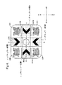
- Authority
- JP
- Japan
- Prior art keywords
- lenticular
- image
- security device
- devices
- security
- Prior art date
- Legal status (The legal status is an assumption and is not a legal conclusion. Google has not performed a legal analysis and makes no representation as to the accuracy of the status listed.)
- Active
Links
Images


Classifications
-
- B—PERFORMING OPERATIONS; TRANSPORTING
- B42—BOOKBINDING; ALBUMS; FILES; SPECIAL PRINTED MATTER
- B42D—BOOKS; BOOK COVERS; LOOSE LEAVES; PRINTED MATTER CHARACTERISED BY IDENTIFICATION OR SECURITY FEATURES; PRINTED MATTER OF SPECIAL FORMAT OR STYLE NOT OTHERWISE PROVIDED FOR; DEVICES FOR USE THEREWITH AND NOT OTHERWISE PROVIDED FOR; MOVABLE-STRIP WRITING OR READING APPARATUS
- B42D25/00—Information-bearing cards or sheet-like structures characterised by identification or security features; Manufacture thereof
- B42D25/30—Identification or security features, e.g. for preventing forgery
- B42D25/324—Reliefs
-
- B—PERFORMING OPERATIONS; TRANSPORTING
- B42—BOOKBINDING; ALBUMS; FILES; SPECIAL PRINTED MATTER
- B42D—BOOKS; BOOK COVERS; LOOSE LEAVES; PRINTED MATTER CHARACTERISED BY IDENTIFICATION OR SECURITY FEATURES; PRINTED MATTER OF SPECIAL FORMAT OR STYLE NOT OTHERWISE PROVIDED FOR; DEVICES FOR USE THEREWITH AND NOT OTHERWISE PROVIDED FOR; MOVABLE-STRIP WRITING OR READING APPARATUS
- B42D25/00—Information-bearing cards or sheet-like structures characterised by identification or security features; Manufacture thereof
- B42D25/20—Information-bearing cards or sheet-like structures characterised by identification or security features; Manufacture thereof characterised by a particular use or purpose
- B42D25/23—Identity cards
-
- B—PERFORMING OPERATIONS; TRANSPORTING
- B42—BOOKBINDING; ALBUMS; FILES; SPECIAL PRINTED MATTER
- B42D—BOOKS; BOOK COVERS; LOOSE LEAVES; PRINTED MATTER CHARACTERISED BY IDENTIFICATION OR SECURITY FEATURES; PRINTED MATTER OF SPECIAL FORMAT OR STYLE NOT OTHERWISE PROVIDED FOR; DEVICES FOR USE THEREWITH AND NOT OTHERWISE PROVIDED FOR; MOVABLE-STRIP WRITING OR READING APPARATUS
- B42D25/00—Information-bearing cards or sheet-like structures characterised by identification or security features; Manufacture thereof
- B42D25/20—Information-bearing cards or sheet-like structures characterised by identification or security features; Manufacture thereof characterised by a particular use or purpose
- B42D25/24—Passports
-
- B—PERFORMING OPERATIONS; TRANSPORTING
- B42—BOOKBINDING; ALBUMS; FILES; SPECIAL PRINTED MATTER
- B42D—BOOKS; BOOK COVERS; LOOSE LEAVES; PRINTED MATTER CHARACTERISED BY IDENTIFICATION OR SECURITY FEATURES; PRINTED MATTER OF SPECIAL FORMAT OR STYLE NOT OTHERWISE PROVIDED FOR; DEVICES FOR USE THEREWITH AND NOT OTHERWISE PROVIDED FOR; MOVABLE-STRIP WRITING OR READING APPARATUS
- B42D25/00—Information-bearing cards or sheet-like structures characterised by identification or security features; Manufacture thereof
- B42D25/20—Information-bearing cards or sheet-like structures characterised by identification or security features; Manufacture thereof characterised by a particular use or purpose
- B42D25/29—Securities; Bank notes
-
- B—PERFORMING OPERATIONS; TRANSPORTING
- B42—BOOKBINDING; ALBUMS; FILES; SPECIAL PRINTED MATTER
- B42D—BOOKS; BOOK COVERS; LOOSE LEAVES; PRINTED MATTER CHARACTERISED BY IDENTIFICATION OR SECURITY FEATURES; PRINTED MATTER OF SPECIAL FORMAT OR STYLE NOT OTHERWISE PROVIDED FOR; DEVICES FOR USE THEREWITH AND NOT OTHERWISE PROVIDED FOR; MOVABLE-STRIP WRITING OR READING APPARATUS
- B42D25/00—Information-bearing cards or sheet-like structures characterised by identification or security features; Manufacture thereof
- B42D25/30—Identification or security features, e.g. for preventing forgery
- B42D25/328—Diffraction gratings; Holograms
-
- B—PERFORMING OPERATIONS; TRANSPORTING
- B42—BOOKBINDING; ALBUMS; FILES; SPECIAL PRINTED MATTER
- B42D—BOOKS; BOOK COVERS; LOOSE LEAVES; PRINTED MATTER CHARACTERISED BY IDENTIFICATION OR SECURITY FEATURES; PRINTED MATTER OF SPECIAL FORMAT OR STYLE NOT OTHERWISE PROVIDED FOR; DEVICES FOR USE THEREWITH AND NOT OTHERWISE PROVIDED FOR; MOVABLE-STRIP WRITING OR READING APPARATUS
- B42D25/00—Information-bearing cards or sheet-like structures characterised by identification or security features; Manufacture thereof
- B42D25/30—Identification or security features, e.g. for preventing forgery
- B42D25/351—Translucent or partly translucent parts, e.g. windows
-
- G—PHYSICS
- G02—OPTICS
- G02B—OPTICAL ELEMENTS, SYSTEMS OR APPARATUS
- G02B30/00—Optical systems or apparatus for producing three-dimensional [3D] effects, e.g. stereoscopic images
- G02B30/20—Optical systems or apparatus for producing three-dimensional [3D] effects, e.g. stereoscopic images by providing first and second parallax images to an observer's left and right eyes
- G02B30/26—Optical systems or apparatus for producing three-dimensional [3D] effects, e.g. stereoscopic images by providing first and second parallax images to an observer's left and right eyes of the autostereoscopic type
- G02B30/27—Optical systems or apparatus for producing three-dimensional [3D] effects, e.g. stereoscopic images by providing first and second parallax images to an observer's left and right eyes of the autostereoscopic type involving lenticular arrays
-
- B42D2035/20—
-
- B42D2035/44—
-
- B42D2035/50—
-
- Y—GENERAL TAGGING OF NEW TECHNOLOGICAL DEVELOPMENTS; GENERAL TAGGING OF CROSS-SECTIONAL TECHNOLOGIES SPANNING OVER SEVERAL SECTIONS OF THE IPC; TECHNICAL SUBJECTS COVERED BY FORMER USPC CROSS-REFERENCE ART COLLECTIONS [XRACs] AND DIGESTS
- Y10—TECHNICAL SUBJECTS COVERED BY FORMER USPC
- Y10T—TECHNICAL SUBJECTS COVERED BY FORMER US CLASSIFICATION
- Y10T29/00—Metal working
- Y10T29/49—Method of mechanical manufacture
- Y10T29/49826—Assembling or joining
Description
本発明は、セキュリティ装置に関し、例えば、紙幣、小切手、パスポート、IDカード、内容証明書(certificate of authenticity)、収入印紙、及び価値を保護するための他の文書、又は個人IDのような貴重品における使用のためのセキュリティ装置に関する。 The present invention relates to security devices, such as banknotes, checks, passports, ID cards, certificate of authenticity, revenue stamps, and other documents for protecting value, or valuables such as personal IDs. Security device for use in
多くの種々の光学セキュリティ装置が公知であり、最も一般的な光学セキュリティ装置はホログラム及び他の回折型装置であり、これらはクレジットカード及びその均等物において見られることが多い。例えば欧州特許出願公開第1695121号明細書及び国際公開第94/27254号において記述されるようなモアレ拡大レンズ(moire magnifier)の形態においてセキュリティ装置を提供することも公知である。モアレ拡大レンズの欠点はアートワークがより制限されることであり、例えばアニメーション効果はモアレ拡大レンズでは不可能であるだろう。 Many different optical security devices are known, and the most common optical security devices are holograms and other diffractive devices, often found in credit cards and their equivalents. It is also known to provide security devices in the form of moire magnifiers, as described, for example, in EP 1 695 121 A1 and WO 94/27254. A drawback of the Moire magnifying lens is that the artwork is more limited, for example animation effects may not be possible with a Moire magnifying lens.
例えば米国特許出願公開第4892336号明細書において記述されるように、いわゆるレンチキュラー装置がセキュリティ装置として使用されうることも知られてきた。この仕様は二種類のレンチキュラー効果すなわち傾き画像効果(tilt image effect)及び動画効果を記述し、傾き画像効果では装置が傾けられると色が変化し又は画像が観察され、動画効果では観察角度が変化すると画像が装置に沿って動くように見える。二つの効果は例えば一つのセキュリティスレッド(security thread)上において互いに組み合わされることができ、このため、観察角度が変化すると、二つの異なる効果が観察されうる。しかしながら、これら装置は未熟な観察者による検証が困難であった。 It has also been known that so-called lenticular devices can be used as security devices, as described, for example, in US Pat. No. 4,892,336. This specification describes two types of lenticular effects: tilt image effect and animation effect, where the tilt image effect changes color or images when the device is tilted, and the animation effect changes the viewing angle. The image then appears to move along the device. The two effects can be combined with each other on, for example, a security thread, so that two different effects can be observed when the viewing angle changes. However, these devices have been difficult to verify by untrained observers.
本発明の第1態様によれば、セキュリティ装置が少なくとも二つのレンチキュラー装置を具備し、各レンチキュラー装置は、画像ストリップ(image strip)のそれぞれの組の上に配設された細長いレンチキュラー合焦要素の配列(array)を有し、二つのレンチキュラー装置のレンチキュラー合焦要素が延在する細長い方向は異なる。 According to a first aspect of the present invention, the security device comprises at least two lenticular devices, each lenticular device having an elongated lenticular focusing element disposed on a respective set of image strips. The elongate direction in which the lenticular focusing elements of the two lenticular devices extend is different.
本発明の第2態様によれば、セキュリティ装置を製造する方法が少なくとも二つのレンチキュラー装置を提供することを含み、各レンチキュラー装置は、画像ストリップのそれぞれの組の上に配設された細長いレンチキュラー合焦要素の配列を有し、二つのレンチキュラー装置のレンチキュラー合焦要素が延在する細長い方向は異なる。 According to a second aspect of the present invention, a method of manufacturing a security device includes providing at least two lenticular devices, each lenticular device being disposed on a respective set of image strips. Having an array of focusing elements, the elongate directions in which the lenticular focusing elements of the two lenticular devices extend are different.
本発明は、使用者によって容易に検証されうるが製造するのが困難である単純だが安全な装置を提供する。レンチキュラー合焦要素の二つの配列の細長い方向が異なる方向に延在するので、装置が一方の方向と平行な軸線回りに傾けられると、レンチキュラー効果が対応するレンチキュラー装置から観察されるであろうが、他方からは効果が観察されず又は異なる効果が観察されるであろう。 The present invention provides a simple but safe device that can be easily verified by the user but difficult to manufacture. Since the elongated direction of the two arrays of lenticular focusing elements extends in different directions, if the device is tilted about an axis parallel to one direction, the lenticular effect will be observed from the corresponding lenticular device. From the other side, no effect will be observed or a different effect will be observed.
このことは、二つの細長い方向が直交している場合に特に好都合である。この場合、装置が一方の装置の細長い軸線回りに傾けられると、他方の装置からレンチキュラー効果は観察されないであろう。 This is particularly advantageous when the two elongated directions are orthogonal. In this case, if the device is tilted about the elongated axis of one device, no lenticular effect will be observed from the other device.
二つのレンチキュラー装置は、原理上セキュリティ装置上の任意の位置において配設されることができるが、好ましくは互いに近接して構成され、最も好ましくは互いと当接する。このことによって、レンチキュラー装置を配設することと、装置が異なる方向に傾けられるときにレンチキュラー装置が生じさせる効果を比較することとが容易になる。 The two lenticular devices can in principle be arranged at any position on the security device, but are preferably constructed close to each other and most preferably abut against each other. This makes it easier to arrange the lenticular device and to compare the effects that the lenticular device produces when the device is tilted in different directions.
この場合、特に好ましい例では、セキュリティ装置は二つのレンチキュラー装置を有し、二つのレンチキュラー装置は、垂直に観察されるとき、各レンチキュラー装置からの画像部分によって作り上げられた認識可能な画像を観察者の肉眼に与え、画像ストリップはそれぞれの画像部分の種々のビューを画成し、このことによって、セキュリティ装置がレンチキュラー装置のうちのいずれかの細長い方向に対して平行な軸線回りに傾けられると、それぞれの画像部分が横方向に動くように見え、一方、他の画像部分は静止したままである。 In this case, in a particularly preferred example, the security device has two lenticular devices, and when viewed vertically, the two lenticular devices display a recognizable image created by the image portion from each lenticular device to the viewer. The image strip defines various views of the respective image portions, so that when the security device is tilted about an axis parallel to the elongated direction of any of the lenticular devices, Each image portion appears to move laterally, while the other image portions remain stationary.
以下により詳細に説明されるように、この装置は、装置を検証すべく容易に観察可能であるが製造するのが困難であるという独特な効果を与える。 As will be described in more detail below, this device provides the unique effect of being easily observable but difficult to manufacture to verify the device.
レンチキュラー合焦要素についての周期性ひいては最大基準直径(maximum base diameter)は、好ましくは5〜200μm、より好ましくは10〜60μm、更により好ましくは20〜40μmの範囲内である。レンチキュラー合焦要素についてのFナンバーは、好ましくは0.25〜16、より好ましくは0.5〜2の範囲内である。 The periodicity and thus the maximum base diameter for the lenticular focusing element is preferably in the range of 5 to 200 μm, more preferably 10 to 60 μm, even more preferably 20 to 40 μm. The F number for the lenticular focusing element is preferably in the range of 0.25-16, more preferably 0.5-2.
典型的にはレンチキュラー合焦要素はシリンドリカルレンズを具備する。しかしながら、マイクロミラーが使用されてもよい。 Typically, the lenticular focusing element comprises a cylindrical lens. However, micromirrors may be used.
画像ストリップは基材上に単純に印刷されうるが、レリーフ構造(relief structure)を使用して画像ストリップを画成することも可能である。このことによって非常に薄い装置が構築されることができ、このことは、セキュリティ文書と共に使用されるときに特に有益である。 The image strip can simply be printed on the substrate, but it is also possible to define the image strip using a relief structure. This allows a very thin device to be constructed, which is particularly beneficial when used with security documents.
レリーフ構造はエンボス加工又は鋳型硬化(cast-curing)によって形成されうる。述べられた二つのプロセスのうち、鋳型硬化は複製のより高い忠実性を提供する。 The relief structure can be formed by embossing or cast-curing. Of the two processes described, mold curing provides a higher fidelity of replication.
多様な種々のレリーフ構造が、以下により詳細に記述されるように使用されうる。しかしながら、画像ストリップは単純に回折格子領域として画像をエンボス加工し/鋳型硬化させることによって生成されうる。画像の異なる部分が、異なる回折色を備えた領域を提供する格子の異なるピッチ又は異なる方向の使用によって識別されうる。代替的な(且つ/又は追加の識別化)画像構造が、モスアイ(moth-eye)のような反射防止構造(例えば国際公開第2005/106601号参照)、0次回折構造、アステカ構造(Aztec structure)として知られている段状表面のレリーフ光学構造(例えば国際公開第2005/115119号参照)又は単純な散乱構造である。最も多くの用途について、これら構造は明るさ及びコントラストを高めるべく部分的に又は完全に金属化されうる。 A wide variety of relief structures can be used as described in more detail below. However, the image strip can be generated simply by embossing / mold curing the image as a grating area. Different parts of the image can be distinguished by the use of different pitches or different directions of the grating providing areas with different diffractive colors. Alternative (and / or additional identifying) image structures are anti-reflection structures such as moth-eye (see eg WO 2005/106601), zero-order diffractive structures, Aztec structures Stepped surface relief optical structure known as) (see eg WO 2005/115119) or a simple scattering structure. For most applications, these structures can be partially or fully metallized to increase brightness and contrast.
典型的には、各画像ストリップの幅は、50μm未満、好ましくは20μm未満、最も好ましくは5〜10μmの範囲内である。 Typically, the width of each image strip is less than 50 μm, preferably less than 20 μm, and most preferably in the range of 5-10 μm.
本発明に係るセキュリティ装置の典型的な厚みは、2〜100μm、より好ましくは1〜50μmのレンズ高さと共に20〜50μm、最も好ましくは5〜25μmである。レンチキュラー合焦要素についての周期性ひいては最大基準直径は、好ましくは5〜200μm、より好ましくは10〜60μm、更により好ましくは20〜40μmの範囲内である。レンチキュラー合焦要素についてのFナンバーは、好ましくは0.25〜16、より好ましくは0.5〜2の範囲内である。レリーフ深さはレリーフを形成するのに使用される方法に依存し、ここで、レリーフが回折格子によって提供される場合、その深さは典型的には0.05〜1μmの範囲内であり、粗い非回折レリーフ構造が使用される場合、レリーフ深さは、好ましくは0.5〜10μm、更により好ましくは1〜5μmの範囲内である。 The typical thickness of the security device according to the present invention is 20-50 μm, most preferably 5-25 μm with a lens height of 2-100 μm, more preferably 1-50 μm. The periodicity and thus the maximum reference diameter for the lenticular focusing element is preferably in the range of 5 to 200 μm, more preferably 10 to 60 μm, and even more preferably 20 to 40 μm. The F number for the lenticular focusing element is preferably in the range of 0.25-16, more preferably 0.5-2. The relief depth depends on the method used to form the relief, where if the relief is provided by a diffraction grating, the depth is typically in the range of 0.05-1 μm; When a rough non-diffractive relief structure is used, the relief depth is preferably in the range of 0.5-10 μm, even more preferably 1-5 μm.
セキュリティ装置は画像構造の一部又は追加層として金属化層を具備することができる。好ましくは、斯かる層は多数の場所において選択的に脱金属化される。加えて、装置は金属化層上にレジスト層を更に具備することができる。金属化層及び/又はレジスト層は好ましくは認証部(indicia)として構成される。 The security device can comprise a metallization layer as part of the image structure or as an additional layer. Preferably, such layers are selectively demetallized at a number of locations. In addition, the device can further comprise a resist layer on the metallization layer. The metallization layer and / or the resist layer are preferably configured as an indicia.
装置が機械可読であるように構成されることも好ましい。このことは多数の態様において実現されうる。例えば装置の少なくとも一つの層が(光学的に別個の層として)機械可読材料を更に含むことができる。好ましくは、機械可読材料はマグネタイトのような磁気材料である。機械可読材料は外的刺激に対して反応しうる。さらに、機械可読材料が層内に形成されるとき、この層は透明であってもよい。 It is also preferred that the device is configured to be machine readable. This can be realized in a number of ways. For example, at least one layer of the device can further comprise a machine-readable material (as an optically separate layer). Preferably, the machine readable material is a magnetic material such as magnetite. The machine-readable material can respond to external stimuli. Further, when the machine readable material is formed in a layer, the layer may be transparent.
セキュリティ装置は、多くの異なる用途において、例えば価値ある物への取付けによって使用されうる。好ましくは、セキュリティ装置はセキュリティ文書に付着され又はセキュリティ文書内に実質的に含まれる。このため、セキュリティ装置は斯かる文書の表面に取り付けられ又は文書内に部分的に埋め込まれてもよい。セキュリティ装置はセキュリティ文書との使用のために様々な種々の形態をとることができ、これらは、限定されるものではない例として、セキュリティスレッド、セキュリティ繊維、セキュリティパッチ、セキュリティストリップ、セキュリティストライプ又はセキュリティ箔を含む。 Security devices can be used in many different applications, for example by attachment to valuable objects. Preferably, the security device is attached to or substantially contained within the security document. Thus, the security device may be attached to the surface of such a document or partially embedded within the document. The security device can take a variety of different forms for use with security documents, such as, but not limited to, security threads, security fibers, security patches, security strips, security stripes or security Including foil.
本発明に係るセキュリティ装置及び方法のいくつかの例が、以下、添付の図面を参照して記述され且つ公知の装置と対比される。公知のレンチキュラー装置が図1〜3において示される。図1は、画像A〜Gを観察するのに使用される公知のレンチキュラー装置を通した断面を示す。シリンドリカルレンズ2の配列が透明基材4上に構成される。各画像が多数の(例えば10個の)ストリップ内にセグメント化され、画像A〜Gの特定のセグメント化された領域に対応する一組の画像ストリップがレンチキュラー配列の各レンズ2の下に存在する。第1レンズの下のストリップは各々画像A〜Gの第1セグメントに対応し、次のレンズの下のストリップは各々画像A〜Gの第2セグメントに対応し、その後も同様である。各レンズ2は、一つのみのストリップが一つの観察位置から各レンズ2を通して観察されうるようにストリップの平面内に焦点を合わせるように構成される。任意の観察角度において、画像(A、B、C等)のうちの一つに対応するストリップのみが、対応するレンズを通して見られるであろう。示されるように、画像Dの各ストリップが直線上から見られるのに対して、画像C又はEからのストリップは、軸線から数度ずらされて傾けられたときに見られるであろう。 Some examples of security devices and methods according to the present invention will now be described with reference to the accompanying drawings and contrasted with known devices. A known lenticular device is shown in FIGS. FIG. 1 shows a cross-section through a known lenticular device used to observe images AG. An array of cylindrical lenses 2 is formed on the transparent substrate 4. Each image is segmented into multiple (e.g., 10) strips, and a set of image strips corresponding to a particular segmented region of images AG are present under each lens 2 in the lenticular array. . The strip below the first lens each corresponds to the first segment of images A-G, the strip below the next lens each corresponds to the second segment of images A-G, and so on. Each lens 2 is configured to focus in the plane of the strip so that only one strip can be viewed through each lens 2 from one viewing position. At any viewing angle, only the strip corresponding to one of the images (A, B, C, etc.) will be seen through the corresponding lens. As shown, each strip of image D is seen from a straight line, whereas the strip from image C or E will be seen when tilted several degrees off the axis.
ストリップは画像の薄片として構成され、すなわちストリップAは全て一つの画像からの薄片であり、B、C等についても同様である。結果として、装置が傾けられると、一連の画像が見られるであろう。一連の画像は関連付けられ又は関連付けられなくてもよい。最も単純な装置は、装置が傾けられると互いの間で反転する二つの画像を有するであろう。代替的に、画像は、画像が動くように見えるようにレンチキュラーアニメーション効果を発生させるべくストリップからストリップへ横方向にずらされる一連の画像であってもよい。同様に画像から画像への変化はより複雑なアニメーション(画像の一部が準連続形態において変化する)、モーフィング(一つの画像が小ステップにおいて別の画像に変形する)又はズーミング(画像がステップにおいて大きくなり又は小さくなる)を生じさせうる。 The strips are configured as image flakes, that is, strips A are all flakes from one image, and so on for B, C, etc. As a result, a series of images will be seen when the device is tilted. A series of images may or may not be associated. The simplest device will have two images that flip between each other when the device is tilted. Alternatively, the images may be a series of images that are shifted laterally from strip to strip to produce a lenticular animation effect so that the images appear to move. Similarly, changes from image to image are more complex animations (part of the image changes in quasi-continuous form), morphing (one image transforms into another image in small steps) or zooming (images in step Increase or decrease).
図2は斜視図におけるレンチキュラー装置を示すが、単純化のためにレンズに付き二つの画像ストリップのみが示され且つそれぞれA、Bが付される。図2において示される装置の観察者に対する外観が図3において示される。このとき、装置がその頂部が前方に傾けられた状態(ビューTTF)で構成されると、画像ストリップAが見られ、一方、装置がその底部が前方に傾けられた状態(ビューBTF)で構成されると、その後画像ストリップBが見られるであろう。 FIG. 2 shows the lenticular device in perspective view, but for simplicity only two image strips are shown on the lens and are labeled A and B respectively. The appearance of the apparatus shown in FIG. 2 to the viewer is shown in FIG. At this time, if the device is configured with its top tilted forward (view TTF), image strip A is seen, while the device is configured with its bottom tilted forward (view BTF). Once done, image strip B will then be seen.
図4は、互いに対して90°に向けられ且つ(図1及び2と同様の態様において)それぞれの画像ストリップの上に配設される二組のシリンドリカルマイクロレンズ配列が存在する本発明に係る第1の例を示す。この実施形態では、レンチキュラー装置Aは、軸線B−B回りに東西方向に傾けられると、線A−Aに沿って動くV字模様の画像を作り出すべくその画像ストリップと結合するように、南北方向に延在するマイクロレンズ200を有し、各装置は、矢印221A、221Bによって示される相互に反対の方向に動くV字模様を生成する。レンチキュラー装置Bは、軸線A−A回りに南北方向に傾けられると、線B−Bに沿って動くV字模様の画像を生成すべくその画像ストリップと結合するように、東西方向に延在するマイクロレンズ210を有し、各装置は、相互に反対の方向に動くV字模様を生成する。この例では、軸線A−Aに沿って離間された2つのレンチキュラー装置Aと、軸線B−Bに沿って離間された2つのレンチキュラー装置Bとが存在する。一対のレンチキュラー装置A、Bはそれぞれのコーナーにおいて当接する。加えて、5つのホログラフィック発生構造(holographic generating structure)220、222、224、226、228がレンチキュラー装置AとBとの間に画成された空間において配設される。
FIG. 4 shows a first embodiment according to the present invention in which there are two sets of cylindrical microlens arrays that are oriented at 90 ° to each other and are disposed on respective image strips (in a manner similar to FIGS. 1 and 2). An example of 1 is shown. In this embodiment, when the lenticular device A is tilted east-west about the axis BB, it will be coupled to its image strip to produce a V-shaped image that moves along the line A-A. Each device produces a V-shaped pattern that moves in opposite directions as indicated by
図4における例では、セキュリティ装置が、小型シリンドリカルレンズ200、210の曲率が周期的に変動する方向に対して垂直な軸線の周りで傾けられるときにのみそれぞれのレンチキュラーアニメーションが生じることが理解されるべきである。この場合、装置を水平方向に横切るV字模様のレンチキュラーアニメーションは、装置が線B−Bの周りで傾けられるときに線A−Aに沿って生じるであろう。逆に、装置を鉛直方向に横切るV字模様のレンチキュラーアニメーションは、装置が線A−Aの周りで傾けられるときに線B−Bに沿って生じるであろう。アニメーション自体は任意の方向において起こることができ且つ純粋にアートワークに依存する。
In the example in FIG. 4, it is understood that each lenticular animation only occurs when the security device is tilted about an axis perpendicular to the direction in which the curvature of the small
図4におけるホログラフィック発生構造220〜228はホログラム又はDOVID画像要素の形態でありうる。示されるラベル構成(label construction)では、ホログラフィック装置及びレンチキュラー装置は別個の領域に存在するが、この例は単に説明のためにあり、例えばホログラフィック発生構造220〜228が中央の帯又はストリップにおいて配設され、レンチキュラー装置A、Bが両側の一つ以上の領域において配設されうることが理解されるべきである。代替的に、レンチキュラー装置によって提供される画像と、ホログラフィック発生構造によって提供される画像とは、各々単一画像の構成要素を提供することによって単一画像に統合されてもよい。 The holographic generating structures 220-228 in FIG. 4 can be in the form of holograms or DOVID image elements. In the label construction shown, the holographic device and the lenticular device are in separate areas, but this example is for illustration only, for example, the holographic generating structures 220-228 are in a central strip or strip. It should be understood that the lenticular devices A, B may be disposed in one or more regions on both sides. Alternatively, the image provided by the lenticular device and the image provided by the holographic generating structure may each be integrated into a single image by providing a single image component.
好ましい実施形態では、シリンドリカルマイクロレンズ配列及びマイクロ画像ストリップは、少なくとも一つのレンチキュラー装置について、小型シリンドリカルレンズの曲率が周期的に変動する方向がx軸(図4における線A−A)若しくはy軸(図4における線B−B)に対して45°に位置し又は有利とみなされうる角度の間の任意の角度に位置するように構成される。いくつかの装置では、文書が南北方向又は東西方向にのみ傾けられがちであり、装置が全ての傾きで動くように見えうるので、45°の角度が特に有利である。斯かる装置が図5において示され、ここでは、二組のシリンドリカルマイクロレンズ配列200、210は、互いに対して90°に向けられるが、両方ともセキュリティ装置のx軸及びy軸に対して45°にも向けられる。x軸又はy軸の周りで装置を傾けると、両方のレンチキュラー装置はアニメーションを呈し、この場合、各々の装置からのV字模様は装置の中心に向かって動くように見えるであろう。
In a preferred embodiment, the cylindrical microlens array and the micro image strip have, for at least one lenticular device, the direction in which the curvature of the small cylindrical lens varies periodically in the x-axis (line AA in FIG. 4) or y-axis ( It is arranged to lie at any angle between 45 ° with respect to line BB) in FIG. 4 or an angle that may be considered advantageous. In some devices, an angle of 45 ° is particularly advantageous because the document tends to be tilted only in the north-south or east-west direction, and the device can appear to move at all tilts. Such a device is shown in FIG. 5, where the two sets of
図6は、4つの画像ストリップA〜Dを具備する本発明における使用に適切なレンチキュラー装置の例を示し、4つの画像ストリップA〜Dは、レンチキュラーアニメーション効果を生成すべく同一画像の異なるビューである。この例では、ストリップの画像領域は、透明なPETスペーサ層24上に設けられた樹脂層26において一連の隆起領域又は隆起部を生成することによって生成される。シリンドリカルレンズ配列20は層24上の樹脂層21内に鋳型硬化せしめられ又はエンボス加工される。その後、着色されたインクが、典型的にはリソグラフィックプロセス、フレキソ印刷プロセス又はグラビア印刷プロセスを使用して隆起領域上に転写される。図6において示される例では、画像ストリップA及びBは第1の色27で印刷され、画像ストリップC及びDは第2の色28で印刷される。また、この態様では、装置がレンチキュラーアニメーション効果を生成すべく傾けられるとき、観察者がビューBからビューCに動くと、色が変化する画像が見られるであろう。異なる例では、全てのストリップA〜Dが、装置の第1領域において第1の色であり、その後、装置の第2領域において異なる色である。
FIG. 6 shows an example of a lenticular device suitable for use in the present invention comprising four image strips A-D, where the four image strips A-D are in different views of the same image to produce a lenticular animation effect. is there. In this example, the image area of the strip is generated by generating a series of raised areas or ridges in a
更なる実施形態では、ストリップの画像要素が回折格子から形成されるとき、このとき、一つのストリップ又は異なるストリップ内の異なる画像要素が異なる格子によって形成されうる。格子のピッチ又は回転において違いがあってもよい。このことは、複数の色の回折画像を実現するのに使用されることができ、複数の色の回折画像はアニメーションのようなレンチキュラー光学効果も呈するであろう。例えば、図4において示される例においてレンチキュラー装置AについてV字模様を生成する画像ストリップが、各ストリップについて異なる回折トラック(diffraction track)を書くことによって生成される場合、その後、図4における装置が線B−Bの周りで傾けられると、V字模様の色が種々の回折格子によって徐々に変化する間、V字模様のレンチキュラーアニメーションが生じるであろう。斯かる格子を書くための好ましい方法が電子ビーム書き込み技術又はドットマトリックス技術(dot matrix technique)を使用することであるだろう。 In a further embodiment, when the image elements of a strip are formed from a diffraction grating, then different image elements in one strip or different strips can be formed by different gratings. There may be differences in the pitch or rotation of the grating. This can be used to achieve multiple color diffracted images, which would also exhibit lenticular optical effects such as animation. For example, if the image strips that generate the V pattern for lenticular device A in the example shown in FIG. 4 are generated by writing a different diffraction track for each strip, then the device in FIG. When tilted around BB, a V-shaped lenticular animation will occur while the V-shaped color gradually changes with the various gratings. A preferred method for writing such a grating would be to use an electron beam writing technique or a dot matrix technique.
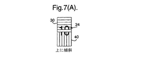
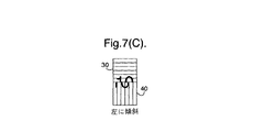
図7及び図7A〜7Hは、本発明に係る別の例を示す。この例では、二つのレンチキュラー装置30、40は互いに当接して設けられ、各々は、図1〜3において示された形態と同様の形態を有する。レンチキュラー装置30は、図7において水平方向に延在するシリンドリカルレンズ32を有し、一方、レンチキュラー装置40は、鉛直方向に延在しひいてはレンズ32に直交するシリンドリカルレンズを有する。
7 and 7A to 7H show another example according to the present invention. In this example, two
レンズ32の下の画像ストリップは、レンチキュラー装置30がレンズ32に対して平行な軸線回りに傾けられると記号「10」の半部分34が上下に又はレンチキュラー装置間の当接点から離れて若しくは当接点に向かって動くように見えるような態様において、数字「10」の上側半部分34を画成する。これら動きは図7A及び図7Bにおいてそれぞれ示される。
The image strip under the
レンチキュラーレンズ42の下では、画像ストリップは、装置がレンズ42の軸線回りに傾けられると下部44が左右にそれぞれ動く(図7C及び7D)ように、44で示されるような記号「10」の下側半部分を表すように画成される。
Under the
概して、画像ストリップがレンズに登録される(registered)が、このことは必須ではない。 Generally, the image strip is registered with the lens, but this is not essential.
図7は、図7E〜7Hそれぞれにおいて、上及び左又は右に傾く効果、並びに下及び左又は右に傾く効果も示す。 FIG. 7 also shows the effect of tilting up and left or right and the effect of tilting down and left or right in FIGS.
装置を単純に傾けることと、予め定められた単純な態様において記号「10」であるように見えるものがその後分割されることを観察することによってセキュリティ効果の存在を判別することが容易であることが図7及び図7A〜7Hから容易に分かるであろう。 It is easy to determine the existence of a security effect by simply tilting the device and observing that what appears to be the symbol “10” in a simple predetermined manner is then split. Can easily be seen from FIGS. 7 and 7A-7H.
図7において示される例では、記号「10」は装置が垂直に観察されるときに完全である。しかしながら、画像とレンズとの間の登録(registration)は、装置が傾けられるときに別の観察条件において記号「10」が完全であるように調整されうる。 In the example shown in FIG. 7, the symbol “10” is complete when the device is viewed vertically. However, the registration between the image and the lens can be adjusted so that the symbol “10” is complete in another viewing condition when the device is tilted.
典型的には、画像ストリップは公知の方法で印刷され、一方、シリンドリカルレンズは適切な樹脂層内にエンボス加工され又は鋳型硬化せしめられる。しかしながら、画像ストリップはレリーフ構造として形成されることもでき、画像ストリップに適切な多様な種々のレリーフ構造が図8において示される。 Typically, image strips are printed in a known manner, while cylindrical lenses are embossed or mold cured in a suitable resin layer. However, the image strip can also be formed as a relief structure, and a variety of different relief structures suitable for the image strip are shown in FIG.
このため、図8Aはエンボス加工された線又は凹み線の形態におけるストリップの画像領域(IM)を示し、一方、エンボス加工されていない線はストリップの非画像領域(NI)に対応する。図8Bは、デボス加工された線又は隆起部の形態におけるストリップの画像領域を示す。 Thus, FIG. 8A shows the image area (IM) of the strip in the form of an embossed or recessed line, while the unembossed line corresponds to the non-image area (NI) of the strip. FIG. 8B shows the image area of the strip in the form of a debossed line or ridge.
別のアプローチでは、レリーフ構造は回折格子(図8C)又はモスアイ格子(moth-eye grating)/ファインピッチ格子(図8D)の形態であってもよい。 In another approach, the relief structure may be in the form of a diffraction grating (FIG. 8C) or a moth-eye grating / fine pitch grating (FIG. 8D).
図8Aの凹部及び図8Bの隆起部には、図8E及び8Fにおいてそれぞれ示されるように、格子が更に設けられうる。 The recess in FIG. 8A and the ridge in FIG. 8B can be further provided with a grid, as shown in FIGS. 8E and 8F, respectively.
図8Gは、色消し効果(achromatic effect)を提供する単純な散乱構造の使用を示す。 FIG. 8G shows the use of a simple scattering structure that provides an achromatic effect.
さらに、上記に説明されるように、いくつかの場合、図8Aの凹部にはインクが提供され、又はデボス加工された領域若しくは隆起部にはインクが提供されうる。後者は図8Hにおいて示され、図8Hではインク層100が隆起部110上に設けられる。 Further, as described above, in some cases, ink may be provided in the recesses of FIG. 8A, or ink may be provided in the debossed areas or ridges. The latter is shown in FIG. 8H, where the ink layer 100 is provided on the ridge 110 in FIG. 8H.
図8Iはアステカ構造の使用を示す。 FIG. 8I illustrates the use of an aztec structure.
代替的に、画像領域及び非画像領域が種々の要素タイプの組合せによって画成され、例えば画像領域がモスアイ構造から形成され、一方、非画像領域が格子から形成されてもよい。また更には、画像領域及び非画像領域は異なるピッチ又は方向の格子によって形成されてもよい。 Alternatively, the image area and the non-image area may be defined by a combination of various element types, for example, the image area may be formed from a moth-eye structure, while the non-image area may be formed from a grid. Still further, the image area and the non-image area may be formed by grids having different pitches or directions.
隆起部/凹部の高さ又は深さは、好ましくは0.5〜10μmの範囲内であり、より好ましくは1〜5μmの範囲内である。隆起部/凹部の典型的な幅は、アートワークの性質によって定義されるであろうが、典型的には100μm未満であり、より好ましくは50μm未満であり、更により好ましくは25μm未満である。画像ストリップの幅ひいては隆起部又は凹部の幅は必要とされる光学効果のタイプに依存し、例えば合焦要素の直径が30μmである場合、このとき、二つのビューAとBとの間の単純な切り換え効果が15μm幅の画像ストリップを使用して実現されうる。代替的に、滑らかなアニメーション効果のために、典型的には少なくとも3個であるが理想的には30個のできるだけ多くのビューを有することが好ましく、この場合、画像ストリップ(及び関連付けられた隆起部又は凹部)の幅は0.1〜6μmの範囲内であるべきである。 The height or depth of the protuberance / recess is preferably in the range of 0.5 to 10 μm, more preferably in the range of 1 to 5 μm. The typical width of the ridge / recess will be defined by the nature of the artwork, but is typically less than 100 μm, more preferably less than 50 μm, and even more preferably less than 25 μm. The width of the image strip and thus the width of the ridges or recesses depends on the type of optical effect required, for example if the focusing element has a diameter of 30 μm, then the simpleness between the two views A and B A simple switching effect can be achieved using a 15 μm wide image strip. Alternatively, for smooth animation effects, it is preferable to have as many views as possible, typically at least 3 but ideally 30, in this case image strips (and associated ridges) The width of the part or recess) should be in the range of 0.1-6 μm.
レリーフ構造の場合、これらは、シリンドリカルレンズとは反対側の基材上の適切な樹脂層内にエンボス加工され又は鋳型硬化せしめられるであろう。 In the case of relief structures, these will be embossed or mold cured in a suitable resin layer on the substrate opposite the cylindrical lens.
レンチキュラー合焦要素がシリンドリカルレンズを参照して記述されるが、他の適切な要素がマイクロミラーを含む。 While lenticular focusing elements are described with reference to cylindrical lenses, other suitable elements include micromirrors.
いくつかの層における検出可能材料の導入又は別個の機械可読層(machine-readable layer)の導入によって、本発明のセキュリティ装置は機械可読にされうる。外的刺激に反応する検出可能材料は、限定されるものではないが、蛍光材料、燐光材料、赤外線吸収材料、サーモクロミック材料、フォトクロミック材料、磁気材料、エレクトロクロミック材料、導電性材料及びピエゾクロミック材料を含む。 The security device of the present invention can be machine readable by introducing a detectable material in several layers or by introducing a separate machine-readable layer. Detectable materials that respond to external stimuli include, but are not limited to, fluorescent materials, phosphorescent materials, infrared absorbing materials, thermochromic materials, photochromic materials, magnetic materials, electrochromic materials, conductive materials, and piezochromic materials including.
本発明のセキュリティ装置は任意の所望の印刷画像又は金属層のような追加のセキュリティ要素も具備することができ、これら追加のセキュリティ要素は不透明であり、半透明であり又は遮蔽されうる。斯かる金属層は、公知の脱金属プロセスによって生成される負又は正の認証部を含むことができる。 The security device of the present invention can also include additional security elements, such as any desired printed image or metal layer, which can be opaque, translucent or masked. Such a metal layer can include a negative or positive authenticator produced by a known metal removal process.
追加の光学可変材料が、薄いフィルム干渉要素(film interference element)、液晶材料及びフォトニック結晶材料のようなセキュリティ装置において含まれうる。斯かる材料は、フィルム層の形態であり、又は印刷による用途に適切な色素材料として存在しうる。 Additional optically variable materials can be included in security devices such as thin film interference elements, liquid crystal materials, and photonic crystal materials. Such a material may be in the form of a film layer or may be present as a suitable dye material for printing applications.
金属層の存在は機械可読な暗い磁気層の存在を隠すのに使用されうる。磁気材料が装置内に組み込まれるとき、磁気材料が任意の設計において適用されうるが、通常の例はコード構造を形成すべく磁気トラムライン(magnetic tramline)又は磁気ブロック(magnetic block)の使用を含む。適切な磁気材料は、酸化鉄顔料(Fe2O3又はFe3O4)、バリウムフェライト、ストロンチウムフェライト、鉄、ニッケル、コバルト及びこれらの合金を含む。この文脈では、「合金」との用語は、ニッケル・コバルト、鉄・アルミニウム・ニッケル・コバルト及びこれらの均等物のような材料を含む。フレークニッケル材料が使用されることができ、加えて鉄フレーク材料が適切である。典型的なニッケルフレークは5〜50μmの範囲内の横寸法及び2μm未満の厚みを有する。典型的な鉄フレークは10〜30μmの範囲内の横寸法及び2μm未満の厚みを有する。 The presence of the metal layer can be used to hide the presence of the machine-readable dark magnetic layer. When the magnetic material is incorporated into the device, the magnetic material can be applied in any design, but typical examples include the use of a magnetic tramline or magnetic block to form a code structure . Suitable magnetic materials include iron oxide pigments (Fe 2 O 3 or Fe 3 O 4 ), barium ferrite, strontium ferrite, iron, nickel, cobalt and alloys thereof. In this context, the term “alloy” includes materials such as nickel-cobalt, iron-aluminum-nickel-cobalt and their equivalents. A flake nickel material can be used, in addition an iron flake material is suitable. Typical nickel flakes have a lateral dimension in the range of 5-50 μm and a thickness of less than 2 μm. Typical iron flakes have a lateral dimension in the range of 10-30 μm and a thickness of less than 2 μm.
代替的な機械可読の実施形態では、透明な磁気層が装置構造内の任意の位置において組み込まれうる。適切な透明な磁気層は、所定の大きさの磁気材料の粒子の分布を含み、磁気層が透明のままである濃度において分配され、国際公開第03091953号及び国際公開第03091952号において記述される。 In alternative machine-readable embodiments, a transparent magnetic layer can be incorporated at any location within the device structure. A suitable transparent magnetic layer includes a distribution of particles of a magnetic material of a predetermined size and is distributed in a concentration at which the magnetic layer remains transparent and is described in WO 03091953 and WO 03091952. .
更なる例では、本発明のセキュリティ装置は、装置が文書の透明領域において組み込まれるように、セキュリティ文書において組み込まれうる。セキュリティ文書は、紙及びポリマーを含む任意の従来の材料から形成された基材を有することができる。これらタイプの基材の各々において透明領域を形成するための技術が当該技術分野において公知である。例えば国際公開第8300659号は、基材の両側に不透明化コーティング(opacifying coating)を具備する透明基材から形成されたポリマー紙幣を記述する。不透明化コーティングは、透明領域を形成すべく基材両側の局所的な領域において省かれる。 In a further example, the security device of the present invention can be incorporated in a security document such that the device is incorporated in a transparent area of the document. The security document can have a substrate formed from any conventional material including paper and polymers. Techniques for forming transparent regions in each of these types of substrates are known in the art. For example, WO 8300659 describes a polymer banknote formed from a transparent substrate with an opacifying coating on both sides of the substrate. The opacifying coating is omitted in local areas on both sides of the substrate to form transparent areas.
欧州特許第114180号明細書は、紙の基材において透明領域を作る方法を記述する。紙の基材において透明領域を形成するための他の方法が、欧州特許第0723501号明細書、欧州特許第0724519号明細書、欧州特許第1398174号明細書及び国際公開第03054297号において記述される。 EP 114180 describes a method for creating a transparent region in a paper substrate. Other methods for forming transparent areas in paper substrates are described in EP 0723501, EP 0724519, EP 1398174 and WO 03054297. .
Claims (22)
各々のレンチキュラー装置が、画像ストリップのそれぞれの組の上に配設された細長いレンチキュラー合焦要素の配列を有し、前記二つのレンチキュラー装置のレンチキュラー合焦要素が延在する細長い方向が異なっており、
前記細長い方向は直交しており、
当該セキュリティ装置が二つのレンチキュラー装置を有し、該二つのレンチキュラー装置は、少なくとも一つの観察条件において観察されるとき、例えば垂直に観察されるとき、各レンチキュラー装置からの画像部分によって作り上げられた認識可能な画像を観察者の肉眼に与え、画像ストリップがそれぞれの画像部分の種々のビューを画成し、このことによって、当該セキュリティ装置が前記二つのレンチキュラー装置のうちのいずれか一方の前記細長い方向に対して平行な軸線回りに傾けられると、前記それぞれの画像部分が横方向に動くように見えるのに対して、他方の画像部分が静止したままである、セキュリティ装置。 A security device comprising at least two lenticular devices,
Each lenticular device has an array of elongate lenticular focusing elements disposed on a respective set of image strips, the elongate directions in which the lenticular focusing elements of the two lenticular devices extend differ. ,
The elongated directions are orthogonal;
The security device has two lenticular devices, the two lenticular devices being recognized by the image portion from each lenticular device when viewed in at least one viewing condition, for example when viewed vertically giving a possible image to the observer's naked eye, it defines the various views of the image strips, each image portion, by this, one of the elongated direction of the security device the two lenticular device When tilted in a parallel axis line with respect, whereas the respective image portions Ru appeared to move laterally, remain the other image portion is stationary, the security device.
各々のレンチキュラー装置が、画像ストリップのそれぞれの組の上に配設された細長いレンチキュラー合焦要素の配列を有し、前記二つのレンチキュラー装置のレンチキュラー合焦要素が延在する細長い方向が異なっており、
前記画像ストリップがレリーフ構造によって画成される、セキュリティ装置。 A security device comprising at least two lenticular devices,
Each lenticular device has an array of elongate lenticular focusing elements disposed on a respective set of image strips, the elongate directions in which the lenticular focusing elements of the two lenticular devices extend differ. ,
A security device, wherein the image strip is defined by a relief structure.
前記物品が、紙幣、小切手、パスポート、IDカード、内容証明書、収入印紙、及び価値を保護するための他の文書、又は個人IDから選択されたものであり、
前記物品が、前記レンチキュラー合焦要素及び画像ストリップがそれぞれ設けられる基材の反対側に、透明部分を備えた基材を具備する、物品。 An article provided with the security device according to any one of claims 1 to 15 ,
The article is selected from banknotes, checks, passports, ID cards, content certificates, revenue stamps, and other documents to protect value, or personal IDs;
An article comprising a substrate with a transparent portion on the opposite side of the substrate on which the lenticular focusing element and image strip are each provided.
当該方法が少なくとも二つのレンチキュラー装置を提供することを含み、各レンチキュラー装置が、画像ストリップのそれぞれの組の上に配設された細長いレンチキュラー合焦要素の配列を有し、前記二つのレンチキュラー装置のレンチキュラー合焦要素が延在する細長い方向が異なっており、
前記細長い方向が直交しており、
前記セキュリティ装置が二つのレンチキュラー装置を有し、該二つのレンチキュラー装置は、少なくとも一つの観察条件において観察されるとき、例えば垂直に観察されるとき、各レンチキュラー装置からの画像部分によって作り上げられた認識可能な画像を観察者の肉眼に与え、画像ストリップがそれぞれの画像部分の種々のビューを画成し、このことによって、前記セキュリティ装置が前記二つのレンチキュラー装置のうちのいずれか一方の前記細長い方向に対して平行な軸線回りに傾けられると、前記それぞれの画像部分が横方向に動くように見えるのに対して、他方の画像部分が静止したままである、方法。 A method of manufacturing a security device, comprising:
The method includes providing at least two lenticular devices, each lenticular device having an array of elongated lenticular focusing elements disposed on a respective set of image strips, The elongated direction in which the lenticular focusing element extends is different,
The elongated directions are orthogonal,
The security device has two lenticular devices, the two lenticular devices being recognized by image portions from each lenticular device when viewed in at least one viewing condition, for example when viewed vertically giving a possible image to the observer's naked eye, it defines the various views of the image strips, each image portion, by this, one of the elongated direction of said security device the two lenticular device When tilted in a parallel axis line with respect, whereas the respective image portions Ru appeared to move laterally, remain the other image portion is stationary, manner.
当該方法が少なくとも二つのレンチキュラー装置を提供することを含み、各レンチキュラー装置が、画像ストリップのそれぞれの組の上に配設された細長いレンチキュラー合焦要素の配列を有し、前記二つのレンチキュラー装置のレンチキュラー合焦要素が延在する細長い方向が異なっており、
前記画像ストリップがレリーフ構造によって画成される、方法。 A method of manufacturing a security device, comprising:
The method includes providing at least two lenticular devices, each lenticular device having an array of elongated lenticular focusing elements disposed on a respective set of image strips, The elongated direction in which the lenticular focusing element extends is different,
The method wherein the image strip is defined by a relief structure.
Applications Claiming Priority (5)
| Application Number | Priority Date | Filing Date | Title |
|---|---|---|---|
| US27277109P | 2009-10-30 | 2009-10-30 | |
| GB0919109.9 | 2009-10-30 | ||
| US61/272,771 | 2009-10-30 | ||
| GBGB0919109.9A GB0919109D0 (en) | 2009-10-30 | 2009-10-30 | Security device |
| PCT/GB2010/001994 WO2011051669A1 (en) | 2009-10-30 | 2010-10-27 | Security device and method of manufacturing the same |
Publications (2)
| Publication Number | Publication Date |
|---|---|
| JP2013509313A JP2013509313A (en) | 2013-03-14 |
| JP5922580B2 true JP5922580B2 (en) | 2016-05-24 |
Family
ID=41434969
Family Applications (1)
| Application Number | Title | Priority Date | Filing Date |
|---|---|---|---|
| JP2012535918A Active JP5922580B2 (en) | 2009-10-30 | 2010-10-27 | Security device and security device manufacturing method |
Country Status (9)
| Country | Link |
|---|---|
| US (1) | US20120268819A1 (en) |
| EP (1) | EP2493699B1 (en) |
| JP (1) | JP5922580B2 (en) |
| CN (1) | CN102712204A (en) |
| AU (1) | AU2010311163B2 (en) |
| GB (1) | GB0919109D0 (en) |
| IN (1) | IN2012DN02747A (en) |
| MX (1) | MX2012004483A (en) |
| WO (1) | WO2011051669A1 (en) |
Families Citing this family (41)
| Publication number | Priority date | Publication date | Assignee | Title |
|---|---|---|---|---|
| GB201107657D0 (en) * | 2011-05-09 | 2011-06-22 | Rue De Int Ltd | Security device |
| EP2745165B9 (en) | 2011-08-19 | 2018-07-18 | Visual Physics, LLC | Optionally transferable optical system with a reduced thickness |
| DE102011115125B4 (en) | 2011-10-07 | 2021-10-07 | Giesecke+Devrient Currency Technology Gmbh | Manufacture of a micro-optical display arrangement |
| JP6053932B2 (en) | 2012-08-17 | 2016-12-27 | ビジュアル フィジクス エルエルシー | The process of transferring the microstructure to the final substrate |
| EP2969585B1 (en) | 2013-03-15 | 2019-04-24 | Visual Physics, LLC | Optical security device |
| US9873281B2 (en) | 2013-06-13 | 2018-01-23 | Visual Physics, Llc | Single layer image projection film |
| GB201313362D0 (en) * | 2013-07-26 | 2013-09-11 | Rue De Int Ltd | Security Devices and Methods of Manufacture |
| GB201313363D0 (en) * | 2013-07-26 | 2013-09-11 | Rue De Int Ltd | Security devices and method of manufacture |
| AU2015235889B2 (en) | 2014-03-27 | 2018-10-11 | Visual Physics, Llc | An optical device that produces flicker-like optical effects |
| US10766292B2 (en) | 2014-03-27 | 2020-09-08 | Crane & Co., Inc. | Optical device that provides flicker-like optical effects |
| KR101960202B1 (en) * | 2014-07-15 | 2019-03-19 | 도판 인사츠 가부시키가이샤 | Booklet |
| EP3169531B1 (en) | 2014-07-17 | 2019-03-06 | Visual Physics, LLC | An improved polymeric sheet material for use in making polymeric security documents such as banknotes |
| KR102497982B1 (en) * | 2014-09-16 | 2023-02-09 | 크레인 시큐리티 테크놀로지스, 인크. | Secure lens layer |
| KR20170110699A (en) | 2015-02-11 | 2017-10-11 | 크레인 앤 코, 인크 | Method for surface application of a security device to a substrate |
| GB2536877B (en) | 2015-03-23 | 2017-06-28 | De La Rue Int Ltd | Security device and method of manufacture |
| DE102015005911A1 (en) * | 2015-05-07 | 2016-11-10 | Giesecke & Devrient Gmbh | Optically variable security element |
| GB2549215B (en) | 2015-06-10 | 2018-07-25 | De La Rue Int Ltd | Security devices and methods of manufacture thereof |
| MA42904A (en) | 2015-07-10 | 2018-05-16 | De La Rue Int Ltd | PROCESSES FOR MANUFACTURING SAFETY DOCUMENTS AND SAFETY DEVICES |
| JP6564279B2 (en) * | 2015-08-27 | 2019-08-21 | 株式会社トプコン | Standard and leveling method |
| JP2017058585A (en) * | 2015-09-18 | 2017-03-23 | 株式会社エンプラス | Image display body, manufacturing method of the same, and optical component |
| GB201520085D0 (en) * | 2015-11-13 | 2015-12-30 | Rue De Int Ltd | Methods of manufacturing image element arrays for security devices |
| CN108603949B (en) * | 2015-12-18 | 2020-10-23 | 光学物理有限责任公司 | Single layer image projection film |
| GB2549724B (en) | 2016-04-26 | 2019-12-11 | De La Rue Int Ltd | Security devices and methods of manufacturing image patterns for security devices |
| JP7316791B2 (en) * | 2016-04-29 | 2023-07-28 | ヌブル インク | Monolithic visible wavelength fiber laser |
| GB2550168B (en) | 2016-05-11 | 2018-07-25 | De La Rue Int Ltd | Security device and method of manufacture |
| GB2557167B (en) | 2016-09-30 | 2020-03-04 | De La Rue Int Ltd | Security devices |
| CN110582412B (en) | 2017-02-10 | 2022-08-30 | 克瑞尼股份有限公司 | Machine readable optical security device |
| GB2564122B (en) * | 2017-07-04 | 2021-01-13 | De La Rue Int Ltd | Optical devices and methods for their manufacture |
| EP3743770A1 (en) * | 2018-01-23 | 2020-12-02 | Multi-Color Corporation | Label including a lens array |
| NL2020650B1 (en) * | 2018-03-23 | 2019-10-02 | Idemia The Netherlands B V | Security document with array of parallel semi-cylindrical lenses |
| FR3087015B1 (en) * | 2018-10-08 | 2022-11-11 | Plastic Omnium Cie | BODY PART COMPRISING A LENTICULAR WALL TO FORM A HOLOGRAPHIC IMAGE |
| GB2578117B (en) | 2018-10-16 | 2021-06-09 | De La Rue Int Ltd | Security devices and methods for their manufacture |
| GB2578773B (en) | 2018-11-08 | 2022-03-30 | De La Rue Int Ltd | Methods of manufacturing security device components |
| GB2580069B (en) | 2018-12-20 | 2022-06-15 | De La Rue Int Ltd | Security documents and methods of manufacture thereof |
| GB2584597B (en) | 2019-03-28 | 2023-01-18 | De La Rue Int Ltd | Security device and method of manufacture thereof |
| GB2588625B (en) | 2019-10-29 | 2022-12-14 | De La Rue Int Ltd | Method of forming a security device |
| JP2020173448A (en) * | 2020-06-04 | 2020-10-22 | 株式会社エンプラス | Image display body, manufacturing method of the same, and optical component |
| EP4210965A2 (en) | 2020-09-11 | 2023-07-19 | De La Rue International Limited | Security devices and methods of manufacture thereof |
| GB202101267D0 (en) | 2021-01-29 | 2021-03-17 | De La Rue Int Ltd | Security devices and methods of manufacture thereof |
| WO2023170132A1 (en) | 2022-03-10 | 2023-09-14 | Basf Se | Casting lacquer for screen printing |
| GB2621154A (en) | 2022-08-03 | 2024-02-07 | De La Rue Int Ltd | Security devices and methods of manufacture thereof |
Family Cites Families (24)
| Publication number | Priority date | Publication date | Assignee | Title |
|---|---|---|---|---|
| US4033059A (en) * | 1972-07-06 | 1977-07-05 | American Bank Note Company | Documents of value including intaglio printed transitory images |
| GB2125337B (en) | 1981-08-24 | 1985-05-01 | Commw Scient Ind Res Org | Improved banknotes and the like |
| DE3609090A1 (en) * | 1986-03-18 | 1987-09-24 | Gao Ges Automation Org | SECURITY PAPER WITH SECURED THREAD STORED IN IT AND METHOD FOR THE PRODUCTION THEREOF |
| US4869946A (en) * | 1987-12-29 | 1989-09-26 | Nimslo Corporation | Tamperproof security card |
| GB9309673D0 (en) | 1993-05-11 | 1993-06-23 | De La Rue Holographics Ltd | Security device |
| AT401365B (en) | 1993-10-11 | 1996-08-26 | Oesterr Nationalbank | SECURITIES |
| DE4334847A1 (en) | 1993-10-13 | 1995-04-20 | Kurz Leonhard Fa | Value document with window |
| GB9828770D0 (en) | 1998-12-29 | 1999-02-17 | Rue De Int Ltd | Security paper |
| BR0007172A (en) * | 1999-09-30 | 2001-09-04 | Koninkl Philips Electronics Nv | Lenticular device, and, set of lenticular devices |
| DE10163381A1 (en) | 2001-12-21 | 2003-07-03 | Giesecke & Devrient Gmbh | Security paper and method and device for its production |
| GB0209564D0 (en) | 2002-04-25 | 2002-06-05 | Rue De Int Ltd | Improvements in substrates |
| EP1398174A1 (en) | 2002-09-10 | 2004-03-17 | Kba-Giori S.A. | Reinforced substrate for securities |
| JP4287131B2 (en) * | 2002-12-09 | 2009-07-01 | 大日本印刷株式会社 | Authenticator |
| DE202004021714U1 (en) | 2003-11-21 | 2010-09-23 | Visual Physics, Llc | Micro-optical security and image presentation system |
| US20070273679A1 (en) * | 2004-03-08 | 2007-11-29 | Barton Daniel J | Orientation data collection system |
| EP2631085B1 (en) | 2004-04-30 | 2019-04-24 | De La Rue International Limited | Arrays of microlenses and arrays of microimages on transparent security substrates |
| US7262856B2 (en) | 2004-05-25 | 2007-08-28 | Hobbs Douglas S | Microstructured optical device for remote chemical sensing |
| JP2006227081A (en) * | 2005-02-15 | 2006-08-31 | Sankoo:Kk | Lenticular effect printed matter and mold for forming refraction section |
| NL1028776C2 (en) * | 2005-04-14 | 2006-10-20 | Sdu Identification Bv | Identification and method for the manufacture thereof. |
| DE102005039113A1 (en) * | 2005-08-18 | 2007-02-22 | Zintzmeyer, Jörg | Microrefraction |
| JP4978102B2 (en) * | 2006-08-07 | 2012-07-18 | セイコーエプソン株式会社 | Print media |
| GB2454752B (en) * | 2007-11-19 | 2012-05-23 | Rue De Int Ltd | Improvements in security devices |
| JP2009255320A (en) * | 2008-04-14 | 2009-11-05 | Dainippon Printing Co Ltd | Identification card |
| US8351087B2 (en) * | 2009-06-15 | 2013-01-08 | Ecole Polytechnique Federale De Lausanne (Epfl) | Authentication with built-in encryption by using moire parallax effects between fixed correlated s-random layers |
-
2009
- 2009-10-30 GB GBGB0919109.9A patent/GB0919109D0/en not_active Ceased
-
2010
- 2010-10-27 JP JP2012535918A patent/JP5922580B2/en active Active
- 2010-10-27 WO PCT/GB2010/001994 patent/WO2011051669A1/en active Application Filing
- 2010-10-27 IN IN2747DEN2012 patent/IN2012DN02747A/en unknown
- 2010-10-27 AU AU2010311163A patent/AU2010311163B2/en not_active Ceased
- 2010-10-27 MX MX2012004483A patent/MX2012004483A/en active IP Right Grant
- 2010-10-27 US US13/499,386 patent/US20120268819A1/en not_active Abandoned
- 2010-10-27 EP EP10775855.9A patent/EP2493699B1/en not_active Not-in-force
- 2010-10-27 CN CN2010800491766A patent/CN102712204A/en active Pending
Also Published As
| Publication number | Publication date |
|---|---|
| EP2493699A1 (en) | 2012-09-05 |
| MX2012004483A (en) | 2012-05-08 |
| AU2010311163A1 (en) | 2012-05-03 |
| WO2011051669A1 (en) | 2011-05-05 |
| US20120268819A1 (en) | 2012-10-25 |
| IN2012DN02747A (en) | 2015-09-18 |
| GB0919109D0 (en) | 2009-12-16 |
| AU2010311163B2 (en) | 2014-09-04 |
| EP2493699B1 (en) | 2019-06-19 |
| JP2013509313A (en) | 2013-03-14 |
| CN102712204A (en) | 2012-10-03 |
Similar Documents
| Publication | Publication Date | Title |
|---|---|---|
| JP5922580B2 (en) | Security device and security device manufacturing method | |
| US9429762B2 (en) | Security device | |
| JP5918142B2 (en) | Security device | |
| US9070237B2 (en) | Moire magnification device | |
| US9802437B2 (en) | Security device and method of manufacture | |
| CA2833951C (en) | Security device |
Legal Events
| Date | Code | Title | Description |
|---|---|---|---|
| A621 | Written request for application examination |
Free format text: JAPANESE INTERMEDIATE CODE: A621 Effective date: 20130912 |
|
| A977 | Report on retrieval |
Free format text: JAPANESE INTERMEDIATE CODE: A971007 Effective date: 20140725 |
|
| A131 | Notification of reasons for refusal |
Free format text: JAPANESE INTERMEDIATE CODE: A131 Effective date: 20140729 |
|
| A601 | Written request for extension of time |
Free format text: JAPANESE INTERMEDIATE CODE: A601 Effective date: 20141028 |
|
| A602 | Written permission of extension of time |
Free format text: JAPANESE INTERMEDIATE CODE: A602 Effective date: 20141105 |
|
| A521 | Request for written amendment filed |
Free format text: JAPANESE INTERMEDIATE CODE: A523 Effective date: 20141204 |
|
| A131 | Notification of reasons for refusal |
Free format text: JAPANESE INTERMEDIATE CODE: A131 Effective date: 20150825 |
|
| A521 | Request for written amendment filed |
Free format text: JAPANESE INTERMEDIATE CODE: A523 Effective date: 20151028 |
|
| TRDD | Decision of grant or rejection written | ||
| A01 | Written decision to grant a patent or to grant a registration (utility model) |
Free format text: JAPANESE INTERMEDIATE CODE: A01 Effective date: 20160315 |
|
| A61 | First payment of annual fees (during grant procedure) |
Free format text: JAPANESE INTERMEDIATE CODE: A61 Effective date: 20160414 |
|
| R150 | Certificate of patent or registration of utility model |
Ref document number: 5922580 Country of ref document: JP Free format text: JAPANESE INTERMEDIATE CODE: R150 |
|
| R250 | Receipt of annual fees |
Free format text: JAPANESE INTERMEDIATE CODE: R250 |