JP5922075B2 - Gripper, needle holder and attachment - Google Patents
Gripper, needle holder and attachment Download PDFInfo
- Publication number
- JP5922075B2 JP5922075B2 JP2013200150A JP2013200150A JP5922075B2 JP 5922075 B2 JP5922075 B2 JP 5922075B2 JP 2013200150 A JP2013200150 A JP 2013200150A JP 2013200150 A JP2013200150 A JP 2013200150A JP 5922075 B2 JP5922075 B2 JP 5922075B2
- Authority
- JP
- Japan
- Prior art keywords
- arm
- holding
- rotating
- driving
- rotating member
- Prior art date
- Legal status (The legal status is an assumption and is not a legal conclusion. Google has not performed a legal analysis and makes no representation as to the accuracy of the status listed.)
- Expired - Fee Related
Links
Images


Description
この発明は、狭小空間等において、対象物を垂直接線方向に安定的かつ効率的に取廻すことが可能とされる把持器、及び縫合針を垂直接線方向に安定的かつ効率的に運針することが可能とされる持針器、及び把持器、持針器を構成するためのアタッチメントに関するものである。 The present invention provides a grasper capable of stably and efficiently handling an object in a vertical tangential direction and a suture needle in a narrow space or the like, and stably and efficiently moving a suture needle in the vertical tangential direction. The present invention relates to a needle holder that can be used, a gripper, and an attachment for constituting the needle holder.
周知のように、外科手術においては、狭小空間をはじめとする種々の環境条件で、生体の把持、穿孔、縫合等が必要とされ、そのために、鉗子、持針器等をはじめとする把持器が用いられている(例えば、特許文献1、非特許文献1参照。)。
このような持針器を用いて縫合手技を行なう場合、例えば、縫合針を持針器の長手方向と直交する方向(以下、横方向という場合がある)に把持して、横方向に運針することが一般的である。
As is well known, in surgical operations, grasping, drilling, suturing, etc. of a living body is required under various environmental conditions including a narrow space. For this purpose, graspers such as forceps and needle holders are required. (For example, refer to
When performing a suturing procedure using such a needle holder, for example, the suture needle is grasped in a direction perpendicular to the longitudinal direction of the needle holder (hereinafter sometimes referred to as a lateral direction) and moved in the lateral direction. It is common.
一方、近年、外科手術の分野では、鏡視下手術を必要とする低侵襲手術が増大しており、低侵襲手術では、狭小視野における効率的な把持操作や効率的な縫合手技を行うことが必要である。 On the other hand, in recent years, in the field of surgery, minimally invasive surgery that requires endoscopic surgery is increasing, and in minimally invasive surgery, efficient grasping operations and efficient suturing techniques in a narrow visual field can be performed. is necessary.
このような狭小視野が対象とする狭小空間において、効率的な低侵襲手術を行なうためには、例えば、生体の把持や穿孔等の手技を正確に行ったり、縫合針を持針器の長手方向(以下、垂直接線方向という場合がある)に運針する等、術野の状況に応じた適切な手技をする必要がある。 In order to perform an efficient minimally invasive operation in such a narrow space targeted by such a narrow visual field, for example, a technique such as grasping or drilling a living body is accurately performed, or a suture needle is placed in the longitudinal direction of the needle holder It is necessary to perform an appropriate procedure according to the condition of the operative field, such as moving the needle (hereinafter sometimes referred to as the vertical tangential direction).
このような挟小空間における対象物の姿勢変更、持替え等における把持器による柔軟な把持や、持針器による垂直接線方向の運針は容易ではなく、縫合針を垂直接線方向に運針することが可能な把持器、持針器が開発されて、狭小視野における効率的な低侵襲手術が実用段階を迎えている(例えば、特許文献2参照。)。 Flexible gripping with a gripper when changing the posture of an object in such a pinched space, switching, etc., and moving the needle in the vertical tangential direction with the needle holder are not easy, and it is possible to move the suture needle in the vertical tangential direction. Possible grippers and needle holders have been developed, and efficient minimally invasive surgery in a narrow visual field has entered a practical stage (see, for example, Patent Document 2).
上記特許文献2に記載された把持器、持針器によって、挟小空間における対象物の姿勢変更や垂直接線方向の運針を行うことが可能となったが、挟小空間における対象物の把持や垂直接線方向の運針をさらに安定して容易に行うことが、低侵襲手術を効率的に行なううえで好適であるといえる。
The gripper and the needle holder described in
そこで、発明者らは、挟小空間において縫合針等の対象物を容易かつ安定的に把持して、対象物を垂直接線方向に安定的かつ効率的に取廻すことにより術野の状況に応じて運針等の手技を適切に行うことが可能とされる操作性の高い把持器(持針器)について鋭意研究した結果、対象物を挟持する場合に挟持機構に負荷される力が、挟持機構の姿勢を変更する駆動機構に対して影響を及ぼしにくい構成とすることによって、操作性を大きく向上させることが可能であるとの知見を得た。 Therefore, the inventors can easily and stably grasp an object such as a suture needle in a narrow space and stably and efficiently handle the object in the vertical tangential direction according to the situation of the surgical field. As a result of earnest research on grippers (needle holders) with high operability that enable appropriate handling of needles and the like, the force applied to the pinching mechanism when pinching an object It has been found that the operability can be greatly improved by adopting a configuration that hardly influences the drive mechanism that changes the posture.
本発明は、かかる事情を考慮してなされたものであり、狭小空間等において、縫合針等の対象物を容易かつ安定的に把持して、対象物を垂直接線方向に安定的かつ効率的に取廻すことが可能な把持器、及び縫合針を垂直接線方向に安定的かつ効率的に運針することが可能な持針器及びこれら把持器を構成するためのアタッチメントを提供することを目的とする。 The present invention has been made in consideration of such circumstances, and in a narrow space or the like, an object such as a suture needle can be easily and stably grasped, and the object can be stably and efficiently in the vertical tangential direction. An object of the present invention is to provide a gripper capable of being operated, a needle holder capable of stably and efficiently moving a suture needle in a vertical tangential direction, and an attachment for constructing these grippers. .
上記課題を解決するために、この発明は以下の手段を提案している。
請求項1に記載の発明は、対象物を把持する把持器であって、前記対象物を挟持する第1挟持アーム部を有し支持軸周りに回動可能とされる第1アーム回動部材と、前記第1挟持アーム部と一対とされ前記対象物を前記第1挟持アーム部と協働して挟持する第2挟持アーム部を有し支持軸周りに回動可能とされる第2アーム回動部材と、前記第1アーム回動部材に連結されて前記第1アーム回動部材を回動させる第1アーム駆動部材と、前記第2アーム回動部材に連結されて前記第2アーム回動部材を回動させる第2アーム駆動部材と、前記第1アーム駆動部材及び前記第2アーム駆動部材を介して前記第1アーム回動部材と前記第2アーム回動部材を回動することにより、前記第1挟持アーム部及び前記第2挟持アーム部を開閉させる第1駆動部と、前記支持軸の軸線と平行に形成された回動軸周りに、前記一対の挟持アーム部を回動させる第2駆動部とを備え、前記第1アーム駆動部材は、前記第1アーム回動部材に回動トルクを生じさせる第1連結部と前記第1駆動部とを連結し、前記第2アーム駆動部材は、前記第2アーム回動部材に回動トルクを生じさせる第2連結部と前記第1駆動部とを連結し、前記第1駆動部は、前記第1アーム駆動部材及び前記第2アーム駆動部材を、前記一対の挟持アーム部に対して同方向に進退させることによって、前記第1挟持アーム部と前記第2挟持アーム部とを開閉するように構成され、前記第2駆動部は、前記第1アーム駆動部材及び前記第2アーム駆動部材を互いに反対向きに進退することにより、前記一対の挟持アーム部を前記回動軸の軸線周りに回動させるように構成されていることを特徴とする。
In order to solve the above problems, the present invention proposes the following means.
The invention according to
本発明に係る把持器によれば、第1挟持アーム部を有する第1アーム回動部材と、第2挟持アーム部を有する第2アーム回動部材とが、それぞれ第1アーム駆動部材、第2アーム駆動部材を介して第1駆動部と連結され、第1駆動部を作動することにより、第1アーム回動部材及び第2アーム回動部材を、支持軸周りに回動させることで対象物(持針器の場合には縫合針、以下同じ)を挟持する。
そして、第2駆動部を作動することにより、支持軸の軸線と平行に形成された回動軸周りに一対の挟持アーム部を回動させるので、第1挟持アーム部及び第2挟持アーム部によって対象物を挟持する際の挟持力が、一対の挟持アーム部が回動するのを阻害するようなスラスト力等として、一対の挟持アーム部と回動軸との間に作用することが抑制される。その結果、対象物を安定的かつ効率的に垂直接線方向に取廻し、又は安定的かつ効率的に運針することができる。
この明細書において、対象物とは、生体(一部を含む)や組織、穿孔器具、切開器具、縫合針等を含むものとする。
本発明に係る把持器によれば、第1アーム駆動部材は、第1アーム回動部材に回動トルクを生じさせる第1連結部と第1駆動部とを連結し、第2アーム駆動部材は、第2アーム回動部材に回動トルクを生じさせる第2連結部と第1駆動部とを連結し、第1駆動部は、第1アーム駆動部材及び第2アーム駆動部材を、一対の挟持アーム部に対して同方向に進退させることによって、第1挟持アーム部と第2挟持アーム部とを開閉するので、構造が簡単であり、第1挟持アーム部及び第2挟持アーム部を容易かつ安定して開閉させることが可能となる。
本発明に係る把持器によれば、一対の挟持アーム部は支持軸の軸線と平行に形成された回動軸周りに回動可能に構成されており、第2駆動部は、第1アーム駆動部材及び第2アーム駆動部材を互いに反対向きに進退させることにより、一対の挟持アーム部を回動軸周りに回動されるので、構造が簡単であり、一対の挟持アーム部を容易かつ安定して回動軸周りに回動させることができる。
According to the gripper according to the present invention, the first arm rotating member having the first holding arm portion and the second arm rotating member having the second holding arm portion are the first arm driving member and the second arm rotating member, respectively. The object is connected to the first drive unit via the arm drive member, and the first drive unit is operated to rotate the first arm rotation member and the second arm rotation member around the support shaft. (In the case of a needle holder, a suture needle, the same applies hereinafter).
Then, by operating the second driving unit, so to rotate the pair of holding arm around a rotary shaft formed in the axial and planar row of the support shaft, a first clamping arm and the second clamping arm unit Suppressing that the clamping force when the object is clamped by the actuator acts as a thrust force or the like that inhibits the pair of clamping arm units from rotating between the pair of clamping arm units and the rotation shaft. Is done. As a result, the object can be stably and efficiently moved in the vertical tangential direction, or can be stably and efficiently moved.
In this specification, the object includes a living body (including a part), a tissue, a perforation device, an incision device, a suture needle, and the like.
According to the gripper according to the present invention, the first arm driving member connects the first connecting portion and the first driving portion that generate the rotating torque to the first arm rotating member, and the second arm driving member is The second connecting part that generates the turning torque on the second arm turning member is connected to the first driving part, and the first driving part holds the pair of the first arm driving member and the second arm driving member. By moving forward and backward in the same direction with respect to the arm portion, the first and second sandwiching arm portions are opened and closed, so that the structure is simple and the first and second sandwiching arm portions can be easily and easily opened and closed. It becomes possible to open and close stably.
According to the gripper according to the present invention, the pair of sandwiching arm portions are configured to be rotatable around a rotation shaft formed in parallel with the axis of the support shaft, and the second drive portion is configured to drive the first arm. By moving the member and the second arm driving member back and forth in opposite directions, the pair of sandwiching arm portions are rotated around the pivot shaft, so the structure is simple and the pair of sandwiching arm portions can be easily and stably operated. Can be rotated around the rotation axis.
請求項2に記載の発明は、請求項1に記載の把持器であって、前記第1駆動部は、前記第1アーム駆動部材及び前記第2アーム駆動部材の前記一対の挟持アーム部に対する進退位置を保持して、前記第1挟持アーム部と前記第2挟持アーム部との相対的な姿勢を保持する挟持アーム姿勢保持部材を備えることを特徴とする。
According to a second aspect of the invention, a gripper according to
本発明に係る把持器によれば、第1駆動部は、第1アーム駆動部材及び第2アーム駆動部材の一対の挟持アーム部に対する進退位置を保持することにより、第1挟持アーム部と第2挟持アーム部相互の位置を保持する挟持爪姿勢保持部材を備えているので、第1挟持アーム部及び第2挟持アーム部の開閉動作に引き続き、その開閉状態を保持することができる。したがって、第1挟持アーム部及び第2挟持アーム部による対象物の挟持及び保持を容易かつ安定して行うことができる。 According to the gripper according to the present invention, the first driving unit holds the first and second holding arm units and the second holding unit by holding the advancing and retracting positions of the first arm driving member and the second arm driving member with respect to the pair of holding arm units. Since the holding claw posture holding member that holds the positions of the holding arm portions is provided, the open / closed state of the first holding arm portion and the second holding arm portion can be held following the opening / closing operation of the first holding arm portion and the second holding arm portion. Therefore, it is possible to easily and stably hold and hold the object by the first holding arm portion and the second holding arm portion.
請求項3に記載の発明は、アタッチメントであって、請求項1又は2に記載の把持器に用いられ、前記第1アーム回動部材と、前記第2アーム回動部材とを備え、前記第1アーム回動部材及び前記第2アーム回動部材は、それぞれ前記第1アーム回動部材及び前記第2アーム駆動部材に対して、着脱可能な連結部を備えることを特徴とする。
Invention of Claim 3 is an attachment, Comprising: It is used for the holding device of
本発明に係るアタッチメントによれば、第1アーム回動部材及び第2アーム回動部材が、それぞれ第1アーム回動部材及び第2アーム駆動部材に対して着脱可能な連結部を備えていて、第1アーム回動部材及び第2アーム駆動部材に対して容易かつ効率的に交換することができるので、第1アーム回動部材及び第2アーム回動部材を使い捨てにして、手術における衛生状態を確保することができる。
なお、アタッチメントは、第1アーム回動部材及び第2アーム回動部材の他、回動軸や連結用部材を備えててもよく、連結用部材を備える場合には、連結用部材を介して第1アーム回動部材及び第2アーム駆動部材に連結してもよい。
According to the attachment according to the present invention, the first arm rotating member and the second arm rotating member are each provided with a detachable connecting portion with respect to the first arm rotating member and the second arm driving member, Since the first arm rotating member and the second arm driving member can be easily and efficiently exchanged, the first arm rotating member and the second arm rotating member are made disposable, and the sanitary condition in the operation can be improved. Can be secured.
The attachment may include a rotation shaft and a connection member in addition to the first arm rotation member and the second arm rotation member. When the connection member is provided, the attachment is provided via the connection member. You may connect with a 1st arm rotation member and a 2nd arm drive member.
請求項4に記載の発明は、持針器であって、請求項1又は2に記載の把持器において、前記第1挟持アーム部及び前記第2挟持アーム部により挟持する対象物が縫合針であることを特徴とする。
The invention described in claim 4 is the needle holder, the gripper according to
本発明に係る持針器によれば、第1挟持アーム部及び第2挟持アーム部により縫合針を安定して把持するとともに、狭小空間等において垂直接線方向に安定的かつ効率的に運針することができる。その結果、狭小空間における縫合を、短時間で効率的に行なうことができる。 According to the needle holder according to the present invention, the suture needle is stably held by the first clamping arm portion and the second clamping arm portion, and the needle is stably and efficiently moved in the vertical tangential direction in a narrow space or the like. Can do. As a result, stitching in a narrow space can be performed efficiently in a short time.
本発明に係る把持器によれば、狭小空間において、対象物を垂直接線方向に安定的かつ効率的に取廻すことができる。
また、本発明に係る持針器によれば、狭小空間において、安定的かつ効率的に運針することができる。
また、本発明に係るアタッチメントによれば、第1アーム回動部材及び第2アーム回動部材を、容易かつ効率的に交換することができるので、使い捨てとすることにより、手術における衛生状態を確保することができる。
According to the gripper according to the present invention, an object can be stably and efficiently handled in a vertical tangential direction in a narrow space.
Further, according to the needle holder according to the present invention, it is possible to move the needle stably and efficiently in a narrow space.
Moreover, according to the attachment which concerns on this invention, since a 1st arm rotation member and a 2nd arm rotation member can be replaced | exchanged easily and efficiently, the sanitary state in an operation is ensured by making it disposable. can do.
以下、図1から図8を参照して、この発明の一実施形態に係る持針器(把持器)について説明する。図1は、一実施形態に係る持針器の概略構成を説明する図であり、符号1は持針器を、符号100は持針器1が取り扱う縫合針(対象物)を示している。
Hereinafter, a needle holder (gripper) according to an embodiment of the present invention will be described with reference to FIGS. 1 to 8. FIG. 1 is a diagram illustrating a schematic configuration of a needle holder according to an embodiment.
持針器1は、図1、図2に示すように、挟持部10と、挟持アーム駆動部材20と、第1駆動部30と、第2駆動部50と、持針器本体60とを備えており、例えば、対象物として縫合針100を挟持するとともに、垂直接線方向に運針することができるようになっている。
なお、持針器に代えて、対象物として、生体(一部を含む)や組織、穿孔器具、切開器具等を把持する把持器として用いてもよい。
As shown in FIGS. 1 and 2, the
In place of the needle holder, the object may be used as a grasping device for grasping a living body (including a part), a tissue, a perforation device, an incision device, or the like.
挟持部10は、第1アーム回動部材111と第2アーム回動部材112とを有する一対のアーム回動部材11と、回動軸(支持軸)15と、挟持ホルダ10Dとを備えている。
The holding
第1アーム回動部材111及び第2アーム回動部材112は、回動軸15を支持軸として、それぞれ独立して回動可能とされて回動軸15を中心として互いに開閉可能とされている。また、一対のアーム回動部材11は、回動軸15の周りに回動可能とされている。すなわち、回動軸15は支持軸と軸線を共有する構成とされている。
The first
第1アーム回動部材111は、対象物を挟持する第1挟持アーム部12Aを有するとともに、回動軸15が挿入される回動軸孔111Aと、連結孔(第1連結部)111Bが形成されている。
また、第1挟持アーム部12Aの先端部には、対象物を効率的に挟持するための第1挟持爪部14Aが形成されている。
The first
Further, a first
第2アーム回動部材112は、対象物を挟持する第2挟持アーム部12Bを有するとともに、第1アーム回動部材111と共通の回動軸15が挿入される回動軸孔112Aと、連結孔(第2連結部)112Bが形成されている。
また、第2挟持アーム部12Bの先端部には、対象物を効率的に挟持するための第2挟持爪部14Bが形成されている。
また、第1挟持アーム部12A及び第2挟持アーム部12Bは、対象物をしっかりと挟持することが可能なアーム長に形成されている。
The second
Moreover, the 2nd clamping nail | claw
Moreover, 12 A of 1st clamping arm parts and 12 A of 2nd clamping arm parts are formed in the arm length which can clamp a target object firmly.
そして、第1アーム回動部材111及び第2アーム回動部材112は、それぞれ回動軸15の周りに回動して互いに開閉するように構成されていて、第1挟持アーム部12Aと第2挟持アーム部12Bが協働して、一対の挟持アーム部12として対象物を挟持するように構成されている。
また、第1挟持爪部14A及び第2挟持爪部14Bは、協働して作用する一対の挟持爪部14を構成している。
The first
In addition, the first
挟持ホルダ10Dは、挟持部10の基端側に形成されていて、回動軸15が嵌挿されるとともに、持針器本体60の保護パイプ65に先端側から挿入され、ねじ65Aによって保護パイプ65に対して、着脱可能に取り付けられている。
The sandwiching holder 10D is formed on the proximal end side of the sandwiching
挟持アーム駆動部材20は、挟持部10を構成する一対のアーム回動部材11と、第1駆動部30とを連結するように構成され、第1駆動部30による操作を挟持部10に伝達するとともに、第2駆動部50によって第1駆動部30の姿勢を変化させる操作を挟持部10に伝達するように構成されている。
The sandwiching
挟持アーム駆動部材20は、第1挟持アーム駆動部材201と、第2挟持アーム駆動部材202とを備えている。
第1挟持アーム駆動部材201は、第1アーム回動部材111に連結されて、第1アーム回動部材111を回動軸15の周りに回動可能に構成されている。
また、第2挟持アーム駆動部材202は、第2アーム回動部材112に連結されて、第2アーム回動部材112を回動軸15の周りに回動可能に構成されている。
The sandwiching
The first clamping
The second holding
また、この実施形態では、図1に示すように、挟持アーム駆動部材20は、挟持部10から第1駆動部30に向かって順に配置された第1駆動リンク21と、第2駆動リンク22と、第3駆動リンク23と、第4駆動リンク24と、第5駆動リンク25とを備え、それぞれ、第1挟持アーム駆動部材201及び第2挟持アーム駆動部材202に対応して配置されている。
In this embodiment, as shown in FIG. 1, the sandwiching
第1挟持アーム駆動部材201は、図1に示すように、第1駆動リンク211と、第2駆動リンク221と、第3駆動リンク231と、第4駆動リンク241と、第5駆動リンク251とを備え、第1駆動部30を操作した際の変位を、第1アーム回動部材111に伝達することが可能に構成されている。
As shown in FIG. 1, the first clamping
第1駆動リンク211は、一端側に連結孔211Aが形成されるとともに他端側に連結孔211Bが形成されており、連結孔211Aは第1アーム回動部材111の連結孔111Bと回動自在に連結されている。
The
第2駆動リンク221は、一端側に連結孔221Aが形成されるとともに他端側に連結孔221Bが形成されており、連結孔221Aは、支点201Aにおいて、Eリング止めピン(不図示)により、第1駆動リンク211の連結孔211Bと回動自在に連結されていて、第1駆動リンク211及び第2駆動リンク221を容易に着脱することができるようになっている。なお、Eリング止めピンを適用するかどうかは任意に設定することができる。
The
第3駆動リンク231は、一端側に連結孔231Aが形成されるとともに他端側に連結孔231Bが形成されており、連結孔231Aは、支点201Bにおいて第2駆動リンク221の連結孔221Bと回動自在に連結されている。
The
第4駆動リンク241は、一端側に回動軸孔241Aが形成されて、回動軸孔241Aを中心に回動可能とされるとともに、一端側と他端側の中間位置に連結孔241Bが形成され、他端側に連結孔241Cが形成されている。そして、連結孔241Bは、支点201Cにおいて第3駆動リンク231の連結孔231Bと回動自在に連結されている。
The
第5駆動リンク251は、一端側に連結孔251Aが形成されるとともに他端側に連結孔251Bが形成されており、連結孔251Aは、支点201Dにおいて第4駆動リンク241の連結孔241Bと回動自在に連結されている。また、連結孔251Bは、伝達部材33に連結されている。
The
第2挟持アーム駆動部材202は、図1に示すように、第1駆動リンク212と、第2駆動リンク222と、第3駆動リンク232と、第4駆動リンク242と、第5駆動リンク252とを備え、第1駆動部30を操作した際の変位を、第2アーム回動部材112に伝達することが可能に構成されている。
As shown in FIG. 1, the second holding
第1駆動リンク212は、一端側に連結孔212Aが形成されるとともに他端側に連結孔212Bが形成されており、連結孔212Aは、支点10Bにおいて、Eリング止めピン(不図示)により、第2アーム回動部材112の連結孔112Bと回動自在に連結されている。
The
第2駆動リンク222は、一端側に連結孔222Aが形成されるとともに他端側に連結孔222Bが形成されており、連結孔222Aは、支点202Aにおいて、Eリング止めピン(不図示)により、第1駆動リンク212の連結孔212Bと回動自在に連結されていて、第1駆動リンク212及び第2駆動リンク222を容易に着脱することができるようになっている。
The
第3駆動リンク232は、一端側に連結孔232Aが形成されるとともに他端側に連結孔232Bが形成されており、連結孔232Aは、支点202Bにおいて第2駆動リンク222の連結孔222Bと回動自在に連結されている。
The
第4駆動リンク242は、一端側に回動軸孔242Aが形成されて、回動軸孔242Aを中心に回動可能とされるとともに、一端側と他端側の中間位置に連結孔242Bが形成され、他端側に連結孔242Cが形成されている。そして、連結孔242Bは、支点202Cにおいて第3駆動リンク232の連結孔232Bと回動自在に連結されている。
The
第5駆動リンク252は、一端側に連結孔252Aが形成されるとともに他端側に連結孔252Bが形成されており、連結孔252Aは、支点202Dにおいて第4駆動リンク242の連結孔242Bと回動自在に連結されている。また、連結孔252Bは、伝達部材33に連結されている。
The
以上のように、第1挟持アーム駆動部材201及び第2挟持アーム駆動部材202を、第1駆動リンク21〜第5駆動リンク25を備えたリンク機構により構成することにより、挟持部10と、第1駆動部30及び第2駆動部50との相対的な姿勢の変化を容易かつ安定して吸収することが可能となり、その結果、第1駆動部30の操作及び第2駆動部50の操作を、挟持部10に安定的かつ確実に伝達することができる。
また、この実施形態において、第1挟持アーム部12A及び第2挟持アーム部12Bは、回動軸15の周りに、例えば、±60°(合計120°)の範囲で回動して姿勢を変えることができるようになっている。
As described above, the first clamping
Further, in this embodiment, the first
第1駆動部30は、図1〜図3に示すように、例えば、支持軸31と、支持軸31に向かって進退可能に配置されたピストン部材32と、このピストン部材32が進退された位置を挟持アーム駆動部材20に伝達する伝達部材33と、制御リンク35と、回動操作によって挟持部10の開閉を調整する操作ホイール39とを備えている。
As shown in FIGS. 1 to 3, the
そして、第1駆動部30は、操作ホイール39を回動操作して制御リンク35の姿勢を変化させることにより、ピストン部材32の後部に連結された制御リンク35がピストン部材32を進退量を調整することにより、第1挟持アーム部12Aと第2挟持アーム部12Bを開閉するようになっている。
Then, the
支持軸31は、第4駆動リンク241の回動軸孔241Aと第4駆動リンク242の回動軸孔242Aに挿入されて、第4駆動リンク241及び第4駆動リンク242を、回動軸孔241A及び回動軸孔242Aの中心、すなわち支持軸31の周りに回動可能に支持するように構成されている。
The
ピストン部材32は、例えば、略円柱状に形成されて、第2駆動部50内に収容されていて、支持軸31に対して長手方向に進退可能とされていている。
また、ピストン部材32は、第2駆動部50を操作した場合であっても、第2駆動部50との相対的な位置関係、すなわち支持軸31に対する進退量が保持されるようになっている。
The
Further, the
伝達部材33は、例えば、一端側に連結片331が形成されるとともに他端側に連結片332が形成された略直方体とされていて、連結片331と連結片332の中間位置には、伝達部材33の長手方向と直交する方向にピストン部材32が嵌挿されている。また、伝達部材33とピストン部材32とは、接続ピン33Pにより連結されていて、伝達部材33とピストン部材32が一体に移動可能とされている。
For example, the
連結片331には連結孔331Aが形成されるとともに、連結片332には連結孔332Aが形成されている。
また、連結孔331Aは、支点301Aにおいて、第5駆動リンク251の連結孔251Bと回動可能に連結されている。
また、連結孔332Aは、支点302Aにおいて、第5駆動リンク252の連結孔252Bと回動可能に連結されている。
The connecting
The connecting
Further, the
制御リンク35は、例えば、第1制御リンク36と、第2制御リンク37と、第3制御リンク38とを備え、第1制御リンク36は一端側が第2駆動部50に取り付けられ、他端側には連結孔36Bが形成されている。
The control link 35 includes, for example, a
第2制御リンク37は、一端側に連結孔37Aが形成されるとともに他端側に連結孔36Bが形成されており、連結孔37Aは、支点35Aにおいて第1制御リンク36の連結孔36Bと回動自在に連結されている。
The
第3制御リンク38は、第1アーム381と、第1アーム381と直交して接続された第2アーム382とを有する平面視略L字型に形成されていて、第1アーム381の一端側には連結孔38Aが形成され、連結孔38Aから第2アーム382に至るまでの中間位置には連結孔38Bが形成されている。
The
連結孔38Aは、支点35Bにおいて、第2制御リンク37の連結孔37Bと回動自在に連結され、連結孔38Bは、支点35Cにおいてピストン部材32の後端部に形成された連結孔32Rと連結されている。
また、第3制御リンク38は、第2アーム382の先端側(第1アーム381から離れた側)に、第1アーム381とは反対側に向かって膨出する押圧部位調整部382Aが形成されている。
The
Further, the
操作ホイール39は、ホイール本体39Aと、ホイール本体39Aの中心から突出して形成されたねじ部39Bと、操作ホイール39を持針器本体60に装着するためのねじ孔プラグ39Cとを備えており、ねじ部39Bの先端は、第3制御リンク38の押圧部位調整部382Aに形成された凹部に当接するようになっている。
The
そして、手動によりホイール本体39Aを回動操作することによって、第3制御リンク38を支点35Bの周りに回動させるとともに支点35Cの位置を変位させることにより、支持軸31に対して、ピストン部材32を進退するようになっている。
その結果、第1挟持アーム駆動部材201及び第2挟持アーム駆動部材202が、第1挟持アーム部12A及び第2挟持アーム部12Bを開閉動作させるようになっている。
Then, by manually rotating the wheel
As a result, the first clamping
また、操作ホイール39のねじ部39Bは挟持アーム姿勢保持部材を構成しており、ホイール本体39Aを右回転させてピストン部材32を進退させた場合に、ホイール本体39Aがその位置で保持されて不用意に回動することが抑制される。その結果、第1挟持アーム部12Aと第2挟持アーム部12Bが互いに開く方向に回動することが抑制されて、対象物を確実に挟持することが可能となる。
Further, the threaded
また、ねじ部39Bは、例えば、台形ネジが適用されていて、操作ホイール39は、ねじ部39Bをねじ孔プラグ39Cの内周に形成されたねじ孔に装着することにより持針器本体60に装着することが可能とされている。
ねじ孔プラグ39Cは、ねじ部39Bと対応するねじ孔が内周に形成されるとともに、外周に持針器本体61に取り付けるためのねじ部が形成されている。
Further, for example, a trapezoidal screw is applied to the
The
第2駆動部50は、図1〜図4に示すように、第1駆動部30を構成するピストン部材32を支持軸31の周りに回動可能に保持するピストン回動部材51と、連結部材55と、操作レバー56とを備えており、操作レバー56を操作してピストン回動部材51を支持軸31の周りに回動することによってピストン部材32の向きを変えて、一対の挟持アーム部12の向きを回動軸15の周りに回動することが可能とされている。
As shown in FIGS. 1 to 4, the
ピストン回動部材51は、図4に示すように、ピストン部材32を進退可能に収容するピストン部材収容部52と、トルクアーム部53とを備え、ベアリング54Bを介して支持軸31が挿入される回動孔54が形成されている。
また、トルクアーム部53には、連結孔53Aが形成されていて、連結孔53Aには連結部材55が連結されている。
As shown in FIG. 4, the
Further, the
ピストン回動部材51は、図4に示すように、トルクアーム部53を矢印R53R方向に回動させると、ピストン部材収容部52及びピストン部材32が、矢印R51方向に回動され、トルクアーム部53を矢印R53F方向に回動させると、ピストン部材収容部52及びピストン部材32が、矢印R52方向に回動されるようになっている。
As shown in FIG. 4, when the
また、図4に示すように、トルクアーム部53を矢印R53R方向に回動させて、ピストン部材収容部52及びピストン部材32を矢印R51方向に回動させると、図5(A)、図5(B)に示すように、第2駆動リンク221は矢印T2方向に移動し、第2駆動リンク222は矢印T1方向に移動して、一対の挟持アーム部12は矢印R10方向に回動される。
ここで、図5(A)は一対の挟持アーム部が閉じて回動される状態を、図5(B)は一対の挟持アーム部が開いて回動される状態を示している。
As shown in FIG. 4, when the
Here, FIG. 5A shows a state where the pair of sandwiching arm portions are closed and rotated, and FIG. 5B shows a state where the pair of sandwiching arm portions are opened and rotated.
また、トルクアーム部53を矢印R53F方向に回動させて、ピストン部材収容部52及びピストン部材32を矢印R52方向に回動させると、第2駆動リンク221は矢印T1方向に移動し、第2駆動リンク222は矢印T2方向に移動して、一対の挟持アーム部12は矢印R20方向に回動される。
Further, when the
連結部材55は、一端側に連結孔55Aが形成されるとともに他端側に連結孔55Bが形成されており、連結孔55Aは、支点50Aにおいて、トルクアーム部53の連結孔53Aと連結されている。
The connecting
操作レバー56は、操作部561と、レバー本体部562とを備えている。
操作部561は、環状に形成されて人差指をひっかける環状部を有していて、この環状部から湾曲アーム部561Aが延在して形成されていて、湾曲アーム部561Aに中指をひっかけることにより、操作レバー56を容易に操作することができるようになっている。
レバー本体部562は、一端側に連結孔56Aが形成され、レバー本体部562の中間位置には回動孔56Bが形成されていて、回動孔56Bは持針器本体60に連結されている。
The
The
The lever
また、連結孔56Aは、支点50Bにおいて、連結部材55の連結孔55Bと連結されていて、操作部561を手動操作により回動孔56Bを中心として回動させると、回動孔56Bを中心としてレバー本体部562が回動して、連結部材55を介してトルクアーム部53を回動させ、ピストン部材収容部52及びピストン部材32を支持軸31の周りに回動させるようになっている。
Further, the connecting
持針器本体60は、ケーシング61と、保護パイプ65と、操作者が持針器1を安定して把持するためのグリップ用部材68とを備え、持針器本体60の内部には、挟持アーム駆動部材20と第1駆動部30と第2駆動部50の主要部が外力で破損しないように収容可能とされている。
The needle holder
ケーシング61は、第1駆動部30及び第2駆動部50の操作部(操作ホイール39、操作レバー56)を除く部材を概ね収容することが可能とされた略直方体の形態とされ、両側の側壁部には、操作ホイール39が装着可能な装着用ポート61Hが形成されている。
The
この実施形態において、装着用ポート61Hは、操作者が操作する際の左側に位置する装着用ポート61Hにねじ孔プラグ39Cが装着され、このねじ孔プラグ39Cに操作ホイール39が取り付けられるとともに、右側に位置する装着用ポート61Hはプラグ39Dによって塞がれていて、右利き用に構成されている。
かかる構成とすることにより、操作ホイール39を右側に装着した左利き用の持針器1を容易に構成することができる。
In this embodiment, the mounting
With this configuration, the left-
また、ケーシング61の上部は、先端側が後方側に比較して下方に傾斜する傾斜部が形成されていて、この傾斜部により広い視野を確保することで、操作者が術野において一対の挟持アーム部12を効率よく操作することができるようになっている。
また、ケーシング61の上部には、この傾斜と対応する開口部61Hが形成されるとともに、開口部61Hにはカバー61Cが装着されるようになっている。
Further, the upper portion of the
An
保護パイプ65が位置する一端側の壁部61Aには、この壁部61Aから外方に向かって伸びる筒状部62が形成されている。筒状部62は、内方に壁部61Aを貫通する貫通孔61Bが形成された凹部を有している。
また、壁部61Aの内方側の面には、筒状部62と反対側に向かって平行に伸びる一対の保持壁部61Cが形成されていて、一対の保持壁部61Cの間には、筒状部62から貫通孔61Bを介して配置された挟持アーム駆動部材20が収容されている。
また、保持壁部61Cには、第2駆動部50のピストン回動部材51が、支持軸31及びベアリング54Bを介して回動可能に支持されている。
また、ケーシング61の下部には連結孔61Pが形成されており、支点50Cにおいて、操作レバー56の回動孔56Bが回動可能に連結されている。
A
In addition, a pair of holding wall portions 61C extending in parallel toward the opposite side of the
In addition, the
Further, a connecting
保護パイプ65は、筒状部62の凹部の先端側開口部内周のテーパ部に固定用スリーブ66を挿入したうえで固定用スリーブ66の孔に嵌挿するとともに、筒状部62に形成されたねじ部に袋ナット67を螺合して装着することにより、固定用スリーブ66の外周側から保持されている。
The
保護パイプ65には、挟持アーム駆動部材20が収容されていて、挟持アーム駆動部材20が外力によって破損するのを抑制するとともに、挟持アーム駆動部材20が狭小空間に通じる通路内において、生体及び組織と接触することにより生体組織等を損傷するのを抑制するようになっている。
The
グリップ用部材68は、図1、図2に示すように、例えば、長円を二分割した断面を有すうするブロック状の形態とされており、持針器1を把持した場合に、持針器1を安定して把持することができるようになっている。
As shown in FIGS. 1 and 2, the
次に、持針器1の動作について説明する。
まず、操作ホイール39が左回転された状態では、第3制御リンク38は、支点35Cを中心にして、図3において、二点鎖線で示すような姿勢となる。
その結果、図6(A)に示すように、ピストン部材32は矢印F31方向に引っ張られて後退側に位置するので、挟持アーム駆動部材20を構成する第1挟持アーム駆動部材201及び第2挟持アーム駆動部材202がそれぞれ矢印T1方向に移動し、第1アーム回動部材111及び第2アーム回動部材112を、回動軸15の周りにそれぞれ矢印R11方向及び矢印R12方向に回動して、第1挟持アーム部12A及び第2挟持アーム部12Bが開いた状態とする。
Next, the operation of the
First, in a state in which the
As a result, as shown in FIG. 6A, since the
次に、操作ホイール39を右回転させると、第3制御リンク38は、支点35Cを中心にして、図3において、実線で示すような姿勢となる。
その結果、図6(B)に示すように、ピストン部材32は矢印F33方向に押圧して前進側に位置させるので、挟持アーム駆動部材20を構成する第1挟持アーム駆動部材201及び第2挟持アーム駆動部材202がそれぞれ矢印T2方向に移動し、第1アーム回動部材111及び第2アーム回動部材112を、回動軸15の周りにそれぞれ矢印R21方向及び矢印R22方向に回動して、第1挟持アーム部12A及び第2挟持アーム部12Bを閉じさせる。
Next, when the
As a result, as shown in FIG. 6B, the
次いで、例えば、図6(B)に示すような挟持部10が閉じた状態とする。
そこで、図示しない操作レバーを操作して、図6(C)に示すように、第2駆動部50を矢印R51方向に回動させる。
第2駆動部50を矢印R51方向に回動させると、挟持アーム駆動部材20を構成する第1挟持アーム駆動部材201及び第2挟持アーム駆動部材202は、それぞれ矢印T2方向及び矢印T1方向に移動し、第1アーム回動部材111及び第2アーム回動部材112を、回動軸15の周りに矢印R10方向に回動して、第1挟持アーム部12A及び第2挟持アーム部12Bの姿勢が変化する。
Next, for example, the clamping
Therefore, an operation lever (not shown) is operated to rotate the
When the
次に、図示しない操作レバーを操作して、図6(D)に示すように、第2駆動部50を矢印R52方向に回動させる。
第2駆動部50を矢印R52方向に回動させると、挟持アーム駆動部材20を構成する第1挟持アーム駆動部材201及び第2挟持アーム駆動部材202は、それぞれ矢印T1方向及び矢印T2方向に移動し、第1アーム回動部材111及び第2アーム回動部材112を、回動軸15の周りに矢印R20方向に回動して、第1挟持アーム部12A及び第2挟持アーム部12Bの姿勢が変化する。
Next, an operation lever (not shown) is operated to rotate the
When the
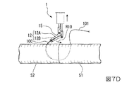
次に、図7A〜図7Dを参照して、持針器1による縫合針100の運針について説明する。図7A〜図7Dにおいて、符号100は縫合針を、符号101は縫合糸を示している。また、符号S1は、縫合針100を先に突き刺す第1の生体組織を、符号S2は、第1の生体組織S1と縫合される生体組織を示している。持針器1による縫合針100の挟持及び回動は、図6(A)〜図6(D)に示すとおりである。
Next, referring to FIG. 7A to FIG. 7D, the operation of the
(1)まず、図7Aに示すように、例えば、第1挟持アーム部12A及び第2挟持アーム部12Bによって、縫合針100を挟持する。
(2)次に、図7Bに示すように、例えば、狭小空間に位置する第1の生体組織S1及び第2の生体組織S2の近傍に、第1挟持アーム部12A及び第2挟持アーム部12Bで挟持した縫合針100を配置する。
そして、第1挟持アーム部12A及び第2挟持アーム部12Bを、回動軸15周りに矢印R20方向に回動して、第1の生体組織S1に対して縫合針100の長手方向に縫合針100を突き刺す。このとき、第1の生体組織S1に対する持針器1の位置は適宜調整する。
(3)次いで、図7Cに示すように、縫合針100を第1の生体組織S1から第2の生体組織S2側に突き出す。
(4)次いで、第1挟持アーム部12A及び第2挟持アーム部12Bを開いて縫合針100を挟持しなおして、第1の生体組織S1と第2の生体組織S2を突き当てるとともに第2の生体組織S2に突き刺して、縫合針100をさらに運針して第1の生体組織S1と第2の生体組織S2を縫合する。
その後、図7Dに示すように、縫合された第2の生体組織S2から縫合針100が突出したら、縫合針100を持ち換える。そして、持ち換えた縫合針100をを、第1挟持アーム部12A及び第2挟持アーム部12Bを回動軸15の周りに矢印R10方向に回動して、縫合針100を第2の生体組織S2から取り出す。このとき、第2の生体組織S2に対する持針器1の位置は適宜調整する。
(1) First, as shown in FIG. 7A, for example, the
(2) Next, as shown in FIG. 7B, for example, in the vicinity of the first living tissue S1 and the second living tissue S2 located in the narrow space, the first
Then, the first
(3) Next, as shown in FIG. 7C, the
(4) Next, the first
Thereafter, as shown in FIG. 7D, when the
次に、図8を参照して、把持器1Aの使用方法の一例について説明する。把持器1Aの構成は、上記持針器1と同様である。図8において、符号120は、腹腔手術において、腹腔内に把持器1Aを挿入する際に用いるトロカーを示しており、例えば、腹腔内において生体(例えば、臓器等)Y1、Y2の奥側に位置する血管Y3の姿勢を変える場合の例を示す図である。
Next, an example of how to use the
まず、図8(A)に示すように、トロカー120を介して腹腔内に把持器1Aを挿入する。
次に、第1挟持アーム部12A及び第2挟持アーム部12Bが開いた状態で操作レバー56を矢印R56F方向に操作して、第1挟持アーム部12A及び第2挟持アーム部12Bを開いた状態で回動させて、血管Y3近傍に配置する。
次いで、操作ホイール39を矢印R39方向に回動する操作をして、第1挟持アーム部12A及び第2挟持アーム部12Bを互いに閉じる側に回動させて、一対の挟持アーム部12によって血管Y3を把持する。
First, as shown in FIG. 8A, the
Next, the operating
Next, the
次に、図8(B)に示すように、操作レバー56を矢印R56R方向に操作して、血管Y3を挟持したまま一対の挟持アーム部12の向きを矢印R20方向に回動させて、血管Y3の向きを変える。
以上のように、把持器1Aを使用することによって、例えば、血管をはじめとする生体の一部や生体組織の姿勢を容易かつ安定して変えることが可能となり、挟小空間内の小さなスペースにおける対象物の把持や向き変更等、困難な手技を効率的に行うことができる。
Next, as shown in FIG. 8B, the
As described above, by using the
一実施形態に係る持針器1によれば、狭小空間において、安定的かつ効率的に運針することができる。
また、一実施形態に係る把持器1Aによれば、狭小空間において、対象物を垂直接線方向に安定的かつ効率的に取廻すことができる。
According to the
Further, according to the
次に、一実施形態に係る持針器1に関して、着脱することが可能なアタッチメント(把持器アタッチメント)について説明する。
アタッチメントは、例えば、挟持部10を一体的に着脱することが可能な構成とされていて、第1アーム回動部材111と、第2アーム回動部材112と、回動軸15とを備えている。なお、第1アーム回動部材111と、第2アーム回動部材112と、回動軸15とを個別に着脱することができる構成としてもよいし、回動軸15を含まない構成や挟持アーム駆動部材20の一部を含む構成としてもよく、任意に設定することが可能である。
Next, regarding the
For example, the attachment is configured such that the holding
挟持部10をアタッチメントとして用いる場合には、例えば、第1アーム回動部材111及び第2アーム回動部材112は、挟持アーム駆動部材20と容易に連結するための連結部を有し、この連結部は、挟持アーム駆動部材20と容易に連結する構成であることが好適であり、例えば、ネジ構造、袋ナットによる連結部、Cリング、Eリングピン、溶接構造、接着等、周知の取付手段を用いることができ、回動軸15、挟持アーム駆動部材20についても同様である。
When the clamping
このようなアタッチメントによれば、第1アーム回動部材111及び第2アーム回動部材112を、容易かつ効率的に交換することができるので、使い捨てとして、手術における衛生状態を確保することができる。
According to such an attachment, the first
なお、この発明は上記実施の形態に限定されるものではなく、発明の趣旨を逸脱しない範囲において、種々の変更をすることができる。
例えば、上記実施の形態においては、第1アーム回動部材111の支持軸と第2アーム回動部材112の支持軸が、ともに回動軸15と共用されている場合について説明したが、第1アーム回動部材111と第2アーム回動部材112のそれぞれの支持軸又はいずれか一方の支持軸を、回動軸15と独立して設けてもよい。
Note that the present invention is not limited to the above-described embodiment, and various modifications can be made without departing from the spirit of the invention.
For example, in the above embodiment, the case where the support shaft of the first
また、上記実施の形態においては、挟持アーム駆動部材20が、第1アーム回動部材111と対応する第1挟持アーム駆動部材201と、第2アーム回動部材112と対応する第2挟持アーム駆動部材202とを備える場合について説明したが、第1アーム回動部材111と第2アーム回動部材112の双方と対応するひとつの部材により挟持アーム駆動部材20を構成してもよい。
In the above-described embodiment, the sandwiching
上記実施の形態においては、第1挟持アーム部12A及び第2挟持アーム部12Bの先端部に、それぞれの第1挟持爪部14A及び第2挟持爪部14Bが形成されている場合について説明したが、第1挟持アーム部12A及び第2挟持アーム部12Bに挟持爪部14を形成するかどうか、挟持爪部14を形成する場合にどのような形状とするかは任意に設定することができる。
In the above embodiment, the case where the first
また、上記実施の形態においては、挟持アーム駆動部材20が、それぞれ5個の駆動リンクにより構成される場合について説明したが、例えば、他の構成からなるリンク機構や、リンク機構に代えて、ワイヤ、ウォームギア、ラック&ピニオン、アクチュエータ(例えば、形状記憶合金、圧電素子、モータ等)等からなる構成やこれらを含む構成としてもよい。
Moreover, in the said embodiment, although the case where the clamping
また、上記実施の形態においては、挟持アーム駆動部材20が、それぞれ5個の駆動リンクにより構成される場合について説明したが、例えば、他の構成からなるリンク機構や、リンク機構に代えて、ワイヤ、ウォームギア、ラック&ピニオン、アクチュエータ(例えば、形状記憶合金、圧電素子、モータ等)等からなる構成やこれらを含む構成としてもよい。
Moreover, in the said embodiment, although the case where the clamping
また、第1駆動部30、第2駆動部50の構成については、一実施形態の構成に限られることなく、任意に設定することができ、ウォームギア、ラック&ピニオン、アクチュエータ(例えば、形状記憶合金、圧電素子、モータ等)等からなる構成やこれらを含む構成としてもよい。
Further, the configuration of the
また、上記実施の形態においては、一対のアーム回動部材11が、±60°(合計120°)の範囲で回動される場合について説明したが、一対のアーム回動部材11の回動角度を何度とするかは、任意に設定することができる。
Moreover, in the said embodiment, although the case where a pair of
また、上記実施の形態においては、第1駆動部30が第1アーム回動部材111及び第2アーム回動部材112を同期して作動させる場合について説明したが、第1駆動部30が第1アーム回動部材111及び第2アーム回動部材112を個別に作動させる構成としてもよい。
Moreover, in the said embodiment, although the
本発明に係る把持器、持針器、及びアタッチメントによれば、狭小空間等において、スムースかつ効率的な対象物の把持、スムースかつ効率的な運針、縫合ができるので、産業上利用可能である。 According to the gripper, the needle holder, and the attachment according to the present invention, smooth and efficient grasping of a target object, smooth and efficient needle movement, and suturing can be performed in a narrow space and the like, which can be used industrially. .
S1、S2 生体組織
Y3 血管(対象物)
1 持針器(把持器)
1A 把持器
10 挟持部
111B 連結孔(第1連結部)
112B 連結孔(第2連結部)
11 一対のアーム回動部材
111 第1アーム回動部材
112 第2アーム回動部材
12 一対の挟持アーム部
12A 第1挟持アーム部
12B 第2挟持アーム部
14 挟持爪部
14A 第1挟持爪部
14B 第2挟持爪部
15 回動軸(支持軸)
20 挟持アーム駆動部材
201 第1挟持アーム駆動部材(第1アーム駆動部材)
202 第2挟持アーム駆動部材(第2アーム駆動部材)
30 第1駆動部
39 操作ホイール(挟持アーム姿勢保持部材)
50 第2駆動部
100 縫合針
S1, S2 Living tissue Y3 Blood vessel (target)
1 Needle holder (gripper)
112B connecting hole (second connecting part)
11 A pair of
20 Clamping
202 2nd clamping arm drive member (2nd arm drive member)
30
50
Claims (4)
前記対象物を挟持する第1挟持アーム部を有し支持軸周りに回動可能とされる第1アーム回動部材と、
前記第1挟持アーム部と一対とされ前記対象物を前記第1挟持アーム部と協働して挟持する第2挟持アーム部を有し支持軸周りに回動可能とされる第2アーム回動部材と、
前記第1アーム回動部材に連結されて前記第1アーム回動部材を回動させる第1アーム駆動部材と、
前記第2アーム回動部材に連結されて前記第2アーム回動部材を回動させる第2アーム駆動部材と、
前記第1アーム駆動部材及び前記第2アーム駆動部材を介して前記第1アーム回動部材と前記第2アーム回動部材を回動することにより、前記第1挟持アーム部及び前記第2挟持アーム部を開閉させる第1駆動部と、
前記支持軸の軸線と平行に形成された回動軸周りに、前記一対の挟持アーム部を回動させる第2駆動部と、
を備え、
前記第1アーム駆動部材は、前記第1アーム回動部材に回動トルクを生じさせる第1連結部と前記第1駆動部とを連結し、
前記第2アーム駆動部材は、前記第2アーム回動部材に回動トルクを生じさせる第2連結部と前記第1駆動部とを連結し、
前記第1駆動部は、
前記第1アーム駆動部材及び前記第2アーム駆動部材を、前記一対の挟持アーム部に対して同方向に進退させることによって、前記第1挟持アーム部と前記第2挟持アーム部とを開閉するように構成され、
前記第2駆動部は、
前記第1アーム駆動部材及び前記第2アーム駆動部材を互いに反対向きに進退することにより、前記一対の挟持アーム部を前記回動軸の軸線周りに回動させるように構成されていることを特徴とする把持器。 A gripper for gripping an object,
A first arm rotating member having a first holding arm portion for holding the object and capable of rotating about a support shaft;
A second arm pivot that is paired with the first sandwich arm and has a second sandwich arm that sandwiches the object in cooperation with the first sandwich arm and is rotatable about a support shaft. Members,
A first arm driving member connected to the first arm rotating member to rotate the first arm rotating member;
A second arm driving member connected to the second arm rotating member to rotate the second arm rotating member;
By rotating the first arm rotating member and the second arm rotating member via the first arm driving member and the second arm driving member, the first holding arm portion and the second holding arm are rotated. A first drive part for opening and closing the part;
To the axis and flat ascending the formed rotating shaft around the support shaft, a second driving unit for rotating the pair of holding arm,
Equipped with a,
The first arm driving member connects the first connecting portion and the first driving portion that generate a rotating torque to the first arm rotating member,
The second arm driving member connects a second connecting portion that generates a rotating torque to the second arm rotating member and the first driving portion,
The first driving unit includes:
The first arm driving member and the second arm driving member are moved forward and backward in the same direction with respect to the pair of holding arm portions so as to open and close the first holding arm portion and the second holding arm portion. Composed of
The second driving unit includes:
By advancing and retracting the opposite the first arm driving member and the second arm driving member to each other, that you are forming the pair of holding arm so as to rotate about the axis of the pivot shaft Characteristic gripper.
前記第1駆動部は、
前記第1アーム駆動部材及び前記第2アーム駆動部材の前記一対の挟持アーム部に対する進退位置を保持して、前記第1挟持アーム部と前記第2挟持アーム部の相対的な位置を保持する挟持アーム姿勢保持部材を備えることを特徴とする把持器。 The gripper according to claim 1 ,
The first driving unit includes:
The holding which hold | maintains the relative position of the said 1st clamping arm part and the said 2nd clamping arm part by hold | maintaining the forward / backward position with respect to the said pair of clamping arm part of the said 1st arm drive member and the said 2nd arm drive member A gripper comprising an arm posture holding member.
Priority Applications (1)
| Application Number | Priority Date | Filing Date | Title |
|---|---|---|---|
| JP2013200150A JP5922075B2 (en) | 2013-09-26 | 2013-09-26 | Gripper, needle holder and attachment |
Applications Claiming Priority (1)
| Application Number | Priority Date | Filing Date | Title |
|---|---|---|---|
| JP2013200150A JP5922075B2 (en) | 2013-09-26 | 2013-09-26 | Gripper, needle holder and attachment |
Publications (2)
| Publication Number | Publication Date |
|---|---|
| JP2015065989A JP2015065989A (en) | 2015-04-13 |
| JP5922075B2 true JP5922075B2 (en) | 2016-05-24 |
Family
ID=52833443
Family Applications (1)
| Application Number | Title | Priority Date | Filing Date |
|---|---|---|---|
| JP2013200150A Expired - Fee Related JP5922075B2 (en) | 2013-09-26 | 2013-09-26 | Gripper, needle holder and attachment |
Country Status (1)
| Country | Link |
|---|---|
| JP (1) | JP5922075B2 (en) |
Families Citing this family (4)
| Publication number | Priority date | Publication date | Assignee | Title |
|---|---|---|---|---|
| JPWO2016063851A1 (en) * | 2014-10-21 | 2017-07-27 | 並木精密宝石株式会社 | Pinching device |
| KR101661452B1 (en) * | 2015-05-22 | 2016-10-10 | 주식회사 엔티로봇 | Micro-suture surgery robot |
| JP6622151B2 (en) * | 2016-06-29 | 2019-12-18 | 株式会社産業情報総合研究所 | Gripper, needle holder and attachment |
| CN111803200B (en) * | 2020-08-28 | 2023-06-09 | 北京和华瑞博医疗科技有限公司 | Needle clamping device and fixing device |
Family Cites Families (9)
| Publication number | Priority date | Publication date | Assignee | Title |
|---|---|---|---|---|
| JP2002253554A (en) * | 2001-03-02 | 2002-09-10 | Japan Science & Technology Corp | Needle holding forceps |
| JP2002263109A (en) * | 2001-03-12 | 2002-09-17 | Olympus Optical Co Ltd | Surgical treating tool |
| JP4402313B2 (en) * | 2001-03-23 | 2010-01-20 | オリンパス株式会社 | Surgical treatment tool and surgical treatment apparatus |
| JP2002291765A (en) * | 2001-03-30 | 2002-10-08 | Olympus Optical Co Ltd | Retainer for surgical treatment appliance |
| JP2003135473A (en) * | 2001-11-01 | 2003-05-13 | Mizuho Co Ltd | Active forceps for endoscopic surgery |
| JP4460890B2 (en) * | 2003-12-15 | 2010-05-12 | 衛 光石 | Multi-DOF manipulator |
| JP2005319164A (en) * | 2004-05-11 | 2005-11-17 | Olympus Corp | Treatment appliance for endoscope |
| JP3884046B2 (en) * | 2005-05-13 | 2007-02-21 | テルモ株式会社 | Surgical instruments |
| JP4972224B1 (en) * | 2011-11-25 | 2012-07-11 | 泉工医科工業株式会社 | Gripper, needle holder and attachment |
-
2013
- 2013-09-26 JP JP2013200150A patent/JP5922075B2/en not_active Expired - Fee Related
Also Published As
| Publication number | Publication date |
|---|---|
| JP2015065989A (en) | 2015-04-13 |
Similar Documents
| Publication | Publication Date | Title |
|---|---|---|
| JP4654165B2 (en) | Working mechanism and manipulator | |
| EP3441017A1 (en) | Geared actuation mechanism and surgical clip applier including the same | |
| JP4972224B1 (en) | Gripper, needle holder and attachment | |
| JP4938156B2 (en) | Surgical forceps | |
| JP3791893B2 (en) | Surgical instrument | |
| KR20070039065A (en) | Semi-robotic suturing device | |
| EP2238919A2 (en) | Endoscopic apparatus for manipulating tissue | |
| JP5922075B2 (en) | Gripper, needle holder and attachment | |
| JP6856363B2 (en) | Powered endoscopic suture device | |
| JP2017529893A (en) | Robot control for grasping mechanical profit | |
| JP2007301692A (en) | Manipulator | |
| JP2017523853A (en) | Robot control for grasping mechanical profit | |
| JP2013529981A (en) | Endoscopic suturing device, system and suturing method | |
| JP5663088B2 (en) | Forceps and forceps unit | |
| JP6622151B2 (en) | Gripper, needle holder and attachment | |
| JP2004154164A (en) | Multi-degree-of-freedom type treating instrument | |
| JP6432175B2 (en) | Endoscopic treatment tool | |
| JP6744700B2 (en) | Grasper and needle holder | |
| WO2017145335A1 (en) | Needle holder for endoscope, suture set, and suture system | |
| WO2011055684A1 (en) | Surgery needle holder | |
| JP5695835B2 (en) | Surgical instrument | |
| JP4989328B2 (en) | Endoscopy forceps | |
| WO2016157211A1 (en) | An automated needle holder and suturing device | |
| JP2005319164A (en) | Treatment appliance for endoscope | |
| WO2021176636A1 (en) | Needle holder for endoscope, and endoscopic suturing method |
Legal Events
| Date | Code | Title | Description |
|---|---|---|---|
| A621 | Written request for application examination |
Free format text: JAPANESE INTERMEDIATE CODE: A621 Effective date: 20150216 |
|
| A977 | Report on retrieval |
Free format text: JAPANESE INTERMEDIATE CODE: A971007 Effective date: 20151016 |
|
| A131 | Notification of reasons for refusal |
Free format text: JAPANESE INTERMEDIATE CODE: A131 Effective date: 20151027 |
|
| A521 | Request for written amendment filed |
Free format text: JAPANESE INTERMEDIATE CODE: A523 Effective date: 20151225 |
|
| TRDD | Decision of grant or rejection written | ||
| A01 | Written decision to grant a patent or to grant a registration (utility model) |
Free format text: JAPANESE INTERMEDIATE CODE: A01 Effective date: 20160322 |
|
| A61 | First payment of annual fees (during grant procedure) |
Free format text: JAPANESE INTERMEDIATE CODE: A61 Effective date: 20160413 |
|
| R150 | Certificate of patent or registration of utility model |
Ref document number: 5922075 Country of ref document: JP Free format text: JAPANESE INTERMEDIATE CODE: R150 |
|
| S111 | Request for change of ownership or part of ownership |
Free format text: JAPANESE INTERMEDIATE CODE: R313113 |
|
| R350 | Written notification of registration of transfer |
Free format text: JAPANESE INTERMEDIATE CODE: R350 |
|
| R250 | Receipt of annual fees |
Free format text: JAPANESE INTERMEDIATE CODE: R250 |
|
| LAPS | Cancellation because of no payment of annual fees |