JP5921429B2 - Sterilizer - Google Patents
Sterilizer Download PDFInfo
- Publication number
- JP5921429B2 JP5921429B2 JP2012511825A JP2012511825A JP5921429B2 JP 5921429 B2 JP5921429 B2 JP 5921429B2 JP 2012511825 A JP2012511825 A JP 2012511825A JP 2012511825 A JP2012511825 A JP 2012511825A JP 5921429 B2 JP5921429 B2 JP 5921429B2
- Authority
- JP
- Japan
- Prior art keywords
- present disclosure
- ballast
- instrument
- luminaire
- housing
- Prior art date
- Legal status (The legal status is an assumption and is not a legal conclusion. Google has not performed a legal analysis and makes no representation as to the accuracy of the status listed.)
- Active
Links
- 238000004659 sterilization and disinfection Methods 0.000 claims description 53
- 230000001954 sterilising effect Effects 0.000 claims description 52
- 230000002070 germicidal effect Effects 0.000 claims description 25
- 230000000844 anti-bacterial effect Effects 0.000 claims description 16
- 238000012423 maintenance Methods 0.000 claims description 16
- 239000000126 substance Substances 0.000 claims description 9
- 239000003899 bactericide agent Substances 0.000 claims description 5
- 238000012360 testing method Methods 0.000 claims description 4
- 230000015556 catabolic process Effects 0.000 claims description 2
- 238000006731 degradation reaction Methods 0.000 claims description 2
- 230000000845 anti-microbial effect Effects 0.000 claims 2
- 239000004599 antimicrobial Substances 0.000 claims 2
- 238000005259 measurement Methods 0.000 claims 2
- 230000011664 signaling Effects 0.000 claims 2
- 230000003115 biocidal effect Effects 0.000 claims 1
- 230000001678 irradiating effect Effects 0.000 claims 1
- 238000009281 ultraviolet germicidal irradiation Methods 0.000 claims 1
- 238000009434 installation Methods 0.000 description 119
- 238000000034 method Methods 0.000 description 72
- 230000007246 mechanism Effects 0.000 description 46
- 238000013461 design Methods 0.000 description 39
- 239000000463 material Substances 0.000 description 19
- 244000005700 microbiome Species 0.000 description 17
- 108020004414 DNA Proteins 0.000 description 14
- 238000005286 illumination Methods 0.000 description 12
- 241000894006 Bacteria Species 0.000 description 8
- 230000008901 benefit Effects 0.000 description 8
- 230000000694 effects Effects 0.000 description 7
- 230000001737 promoting effect Effects 0.000 description 6
- 230000008859 change Effects 0.000 description 5
- 239000003086 colorant Substances 0.000 description 5
- 230000008029 eradication Effects 0.000 description 5
- 238000004519 manufacturing process Methods 0.000 description 5
- RWQNBRDOKXIBIV-UHFFFAOYSA-N thymine Chemical compound CC1=CNC(=O)NC1=O RWQNBRDOKXIBIV-UHFFFAOYSA-N 0.000 description 5
- 238000009423 ventilation Methods 0.000 description 5
- 230000001580 bacterial effect Effects 0.000 description 4
- 230000033228 biological regulation Effects 0.000 description 4
- 238000005516 engineering process Methods 0.000 description 4
- 238000009413 insulation Methods 0.000 description 4
- 230000006378 damage Effects 0.000 description 3
- 238000012986 modification Methods 0.000 description 3
- 230000004048 modification Effects 0.000 description 3
- 230000003287 optical effect Effects 0.000 description 3
- 230000005855 radiation Effects 0.000 description 3
- 229920002799 BoPET Polymers 0.000 description 2
- 241001465754 Metazoa Species 0.000 description 2
- 239000005041 Mylar™ Substances 0.000 description 2
- 108091093078 Pyrimidine dimer Proteins 0.000 description 2
- 238000004378 air conditioning Methods 0.000 description 2
- 238000004040 coloring Methods 0.000 description 2
- 230000008021 deposition Effects 0.000 description 2
- 238000010586 diagram Methods 0.000 description 2
- 230000003760 hair shine Effects 0.000 description 2
- QSHDDOUJBYECFT-UHFFFAOYSA-N mercury Chemical compound [Hg] QSHDDOUJBYECFT-UHFFFAOYSA-N 0.000 description 2
- 229910052751 metal Inorganic materials 0.000 description 2
- 239000002184 metal Substances 0.000 description 2
- 230000000813 microbial effect Effects 0.000 description 2
- 230000008569 process Effects 0.000 description 2
- 238000002310 reflectometry Methods 0.000 description 2
- 229940113082 thymine Drugs 0.000 description 2
- 230000000007 visual effect Effects 0.000 description 2
- 208000019300 CLIPPERS Diseases 0.000 description 1
- 208000003322 Coinfection Diseases 0.000 description 1
- 208000035473 Communicable disease Diseases 0.000 description 1
- 230000005778 DNA damage Effects 0.000 description 1
- 231100000277 DNA damage Toxicity 0.000 description 1
- ASJWEHCPLGMOJE-LJMGSBPFSA-N ac1l3rvh Chemical compound N1C(=O)NC(=O)[C@@]2(C)[C@@]3(C)C(=O)NC(=O)N[C@H]3[C@H]21 ASJWEHCPLGMOJE-LJMGSBPFSA-N 0.000 description 1
- 230000001464 adherent effect Effects 0.000 description 1
- 230000003796 beauty Effects 0.000 description 1
- 230000005540 biological transmission Effects 0.000 description 1
- 238000004364 calculation method Methods 0.000 description 1
- 230000033077 cellular process Effects 0.000 description 1
- 238000006243 chemical reaction Methods 0.000 description 1
- 208000021930 chronic lymphocytic inflammation with pontine perivascular enhancement responsive to steroids Diseases 0.000 description 1
- 238000004140 cleaning Methods 0.000 description 1
- 238000000576 coating method Methods 0.000 description 1
- 238000010411 cooking Methods 0.000 description 1
- 230000007547 defect Effects 0.000 description 1
- 230000003111 delayed effect Effects 0.000 description 1
- 230000001419 dependent effect Effects 0.000 description 1
- 230000000249 desinfective effect Effects 0.000 description 1
- 239000003651 drinking water Substances 0.000 description 1
- 235000020188 drinking water Nutrition 0.000 description 1
- 239000003344 environmental pollutant Substances 0.000 description 1
- 238000007667 floating Methods 0.000 description 1
- 230000004313 glare Effects 0.000 description 1
- 239000011261 inert gas Substances 0.000 description 1
- 208000015181 infectious disease Diseases 0.000 description 1
- 229910052753 mercury Inorganic materials 0.000 description 1
- 239000000203 mixture Substances 0.000 description 1
- 235000016709 nutrition Nutrition 0.000 description 1
- 238000001579 optical reflectometry Methods 0.000 description 1
- 231100000719 pollutant Toxicity 0.000 description 1
- 238000003825 pressing Methods 0.000 description 1
- 230000009467 reduction Effects 0.000 description 1
- 238000009877 rendering Methods 0.000 description 1
- 230000010076 replication Effects 0.000 description 1
- 238000007665 sagging Methods 0.000 description 1
- 238000001228 spectrum Methods 0.000 description 1
- 239000007921 spray Substances 0.000 description 1
- 238000012549 training Methods 0.000 description 1
- 238000009966 trimming Methods 0.000 description 1
- XLYOFNOQVPJJNP-UHFFFAOYSA-N water Substances O XLYOFNOQVPJJNP-UHFFFAOYSA-N 0.000 description 1
Images


Classifications
-
- F—MECHANICAL ENGINEERING; LIGHTING; HEATING; WEAPONS; BLASTING
- F24—HEATING; RANGES; VENTILATING
- F24F—AIR-CONDITIONING; AIR-HUMIDIFICATION; VENTILATION; USE OF AIR CURRENTS FOR SCREENING
- F24F13/00—Details common to, or for air-conditioning, air-humidification, ventilation or use of air currents for screening
- F24F13/02—Ducting arrangements
- F24F13/06—Outlets for directing or distributing air into rooms or spaces, e.g. ceiling air diffuser
- F24F13/078—Outlets for directing or distributing air into rooms or spaces, e.g. ceiling air diffuser combined with lighting fixtures
-
- A—HUMAN NECESSITIES
- A61—MEDICAL OR VETERINARY SCIENCE; HYGIENE
- A61L—METHODS OR APPARATUS FOR STERILISING MATERIALS OR OBJECTS IN GENERAL; DISINFECTION, STERILISATION OR DEODORISATION OF AIR; CHEMICAL ASPECTS OF BANDAGES, DRESSINGS, ABSORBENT PADS OR SURGICAL ARTICLES; MATERIALS FOR BANDAGES, DRESSINGS, ABSORBENT PADS OR SURGICAL ARTICLES
- A61L9/00—Disinfection, sterilisation or deodorisation of air
- A61L9/16—Disinfection, sterilisation or deodorisation of air using physical phenomena
- A61L9/18—Radiation
- A61L9/20—Ultraviolet radiation
-
- F—MECHANICAL ENGINEERING; LIGHTING; HEATING; WEAPONS; BLASTING
- F24—HEATING; RANGES; VENTILATING
- F24F—AIR-CONDITIONING; AIR-HUMIDIFICATION; VENTILATION; USE OF AIR CURRENTS FOR SCREENING
- F24F8/00—Treatment, e.g. purification, of air supplied to human living or working spaces otherwise than by heating, cooling, humidifying or drying
- F24F8/20—Treatment, e.g. purification, of air supplied to human living or working spaces otherwise than by heating, cooling, humidifying or drying by sterilisation
- F24F8/22—Treatment, e.g. purification, of air supplied to human living or working spaces otherwise than by heating, cooling, humidifying or drying by sterilisation using UV light
-
- A—HUMAN NECESSITIES
- A61—MEDICAL OR VETERINARY SCIENCE; HYGIENE
- A61L—METHODS OR APPARATUS FOR STERILISING MATERIALS OR OBJECTS IN GENERAL; DISINFECTION, STERILISATION OR DEODORISATION OF AIR; CHEMICAL ASPECTS OF BANDAGES, DRESSINGS, ABSORBENT PADS OR SURGICAL ARTICLES; MATERIALS FOR BANDAGES, DRESSINGS, ABSORBENT PADS OR SURGICAL ARTICLES
- A61L2209/00—Aspects relating to disinfection, sterilisation or deodorisation of air
- A61L2209/10—Apparatus features
- A61L2209/11—Apparatus for controlling air treatment
- A61L2209/111—Sensor means, e.g. motion, brightness, scent, contaminant sensors
-
- A—HUMAN NECESSITIES
- A61—MEDICAL OR VETERINARY SCIENCE; HYGIENE
- A61L—METHODS OR APPARATUS FOR STERILISING MATERIALS OR OBJECTS IN GENERAL; DISINFECTION, STERILISATION OR DEODORISATION OF AIR; CHEMICAL ASPECTS OF BANDAGES, DRESSINGS, ABSORBENT PADS OR SURGICAL ARTICLES; MATERIALS FOR BANDAGES, DRESSINGS, ABSORBENT PADS OR SURGICAL ARTICLES
- A61L2209/00—Aspects relating to disinfection, sterilisation or deodorisation of air
- A61L2209/10—Apparatus features
- A61L2209/12—Lighting means
-
- A—HUMAN NECESSITIES
- A61—MEDICAL OR VETERINARY SCIENCE; HYGIENE
- A61L—METHODS OR APPARATUS FOR STERILISING MATERIALS OR OBJECTS IN GENERAL; DISINFECTION, STERILISATION OR DEODORISATION OF AIR; CHEMICAL ASPECTS OF BANDAGES, DRESSINGS, ABSORBENT PADS OR SURGICAL ARTICLES; MATERIALS FOR BANDAGES, DRESSINGS, ABSORBENT PADS OR SURGICAL ARTICLES
- A61L2209/00—Aspects relating to disinfection, sterilisation or deodorisation of air
- A61L2209/10—Apparatus features
- A61L2209/15—Supporting means, e.g. stands, hooks, holes for hanging
-
- F—MECHANICAL ENGINEERING; LIGHTING; HEATING; WEAPONS; BLASTING
- F21—LIGHTING
- F21W—INDEXING SCHEME ASSOCIATED WITH SUBCLASSES F21K, F21L, F21S and F21V, RELATING TO USES OR APPLICATIONS OF LIGHTING DEVICES OR SYSTEMS
- F21W2131/00—Use or application of lighting devices or systems not provided for in codes F21W2102/00-F21W2121/00
- F21W2131/20—Lighting for medical use
-
- F—MECHANICAL ENGINEERING; LIGHTING; HEATING; WEAPONS; BLASTING
- F21—LIGHTING
- F21W—INDEXING SCHEME ASSOCIATED WITH SUBCLASSES F21K, F21L, F21S and F21V, RELATING TO USES OR APPLICATIONS OF LIGHTING DEVICES OR SYSTEMS
- F21W2131/00—Use or application of lighting devices or systems not provided for in codes F21W2102/00-F21W2121/00
- F21W2131/40—Lighting for industrial, commercial, recreational or military use
-
- F—MECHANICAL ENGINEERING; LIGHTING; HEATING; WEAPONS; BLASTING
- F21—LIGHTING
- F21Y—INDEXING SCHEME ASSOCIATED WITH SUBCLASSES F21K, F21L, F21S and F21V, RELATING TO THE FORM OR THE KIND OF THE LIGHT SOURCES OR OF THE COLOUR OF THE LIGHT EMITTED
- F21Y2103/00—Elongate light sources, e.g. fluorescent tubes
-
- F—MECHANICAL ENGINEERING; LIGHTING; HEATING; WEAPONS; BLASTING
- F21—LIGHTING
- F21Y—INDEXING SCHEME ASSOCIATED WITH SUBCLASSES F21K, F21L, F21S and F21V, RELATING TO THE FORM OR THE KIND OF THE LIGHT SOURCES OR OF THE COLOUR OF THE LIGHT EMITTED
- F21Y2113/00—Combination of light sources
Landscapes
- Engineering & Computer Science (AREA)
- Chemical & Material Sciences (AREA)
- General Engineering & Computer Science (AREA)
- Mechanical Engineering (AREA)
- Combustion & Propulsion (AREA)
- Health & Medical Sciences (AREA)
- Animal Behavior & Ethology (AREA)
- Veterinary Medicine (AREA)
- Public Health (AREA)
- General Health & Medical Sciences (AREA)
- Life Sciences & Earth Sciences (AREA)
- Epidemiology (AREA)
- Non-Portable Lighting Devices Or Systems Thereof (AREA)
- Arrangement Of Elements, Cooling, Sealing, Or The Like Of Lighting Devices (AREA)
- Apparatus For Disinfection Or Sterilisation (AREA)
Description
本開示は、概して、UV照明と一般的に称される、「紫外線」の使用を通してある浮遊微生物に対する「殺菌による根絶」の分野に関する。より具体的には、本開示は、さらなるUV照明機構を封入するための装置のような、特定の領域を照らすための一次照明源として概して特定される、一般的に使用される照明器具の適合に関する。さらに、本開示は、吊り下げ式格子天井または隙間のない天井と共に使用される、照明器具に統合することができるデバイスに関する。また、本開示は、照明器具と関連して使用される殺菌器具と、新しい殺菌灯器具用の装置、および効率的な殺菌用途のために既存の照明器具を置き換えるまたは変更するための装置とに関する。 The present disclosure relates generally to the field of “eradication by sterilization” against certain airborne microorganisms through the use of “ultraviolet light”, commonly referred to as UV illumination. More specifically, the present disclosure is adapted for commonly used luminaires that are generally identified as primary illumination sources for illuminating specific areas, such as devices for encapsulating additional UV illumination mechanisms. About. Furthermore, the present disclosure relates to a device that can be integrated into a luminaire for use with a suspended lattice ceiling or a ceiling without gaps. The present disclosure also relates to a sterilization instrument used in connection with a lighting fixture, a device for a new germicidal lamp fixture, and a device for replacing or modifying an existing lighting fixture for efficient sterilization applications. .
通常、人が多く集まる施設では、空中に細菌が存在する可能性が最も高く、感染症と関連付けられる浮遊微生物の伝染の割合を減少させる必要性が求められる。直接的な暴露からの即時型の病気、または二次感染に関連する遅効に関するような、感染疾患の人間への影響は、よく報告されている。これらの空中の細菌および微生物を減少することに対する産業の同意が、広く望まれ求められている。また、化学物質等、他の方法による紫外線またはUV光の使用が広く理解されていることがわかっている。 Typically, facilities with a high concentration of people are most likely to have bacteria in the air, and there is a need to reduce the rate of transmission of airborne microorganisms associated with infections. Human effects of infectious diseases, such as immediate illness from direct exposure, or delayed effects associated with secondary infections are well documented. Industry consent to reduce these airborne bacteria and microorganisms is widely desired and desired. It has also been found that the use of UV or UV light by other methods, such as chemicals, is widely understood.
飲料水の栄養価を高めるため、およびカビを減らし、コイル上へ封じ込めを集積する目的で冷暖房空調設備(「HVAC」)システムにて使用するための、水処理におけるUV光の使用には、証明済みの成功実績がある。美容院で使用されるようなバリカンおよび他の道具等、一般用途の機器の表面上にいるバクテリアを殺すUV光の能力は、日常の使用において観察することができる。 The use of UV light in water treatment to increase the nutritional value of drinking water and for use in air conditioning and air conditioning (“HVAC”) systems to reduce mold and consolidate containment on coils Has a successful track record. The ability of UV light to kill bacteria on the surface of general purpose equipment, such as clippers and other tools used in beauty salons, can be observed in daily use.
病室等の領域で微生物を根絶するための最も一般的な方法は、普通、浮遊しているのではなく、対象と直接接触して伝染する微生物に関係する。表面に関連するバクテリアを制御するために現在実践中の方法は、化学雑巾、または消毒スプレーおよび他の種々の接触法に関連付けられる。これらの方法の全ては、バクテリアを効果的に根絶するために、微生物との直接接触が必要であり、長時間が必要なものもある。ほとんどの場合、存在する微生物の大多数は殺されない。微生物が殺されないのには多くの理由があり、例えば、化学物質が蒸発するのが速すぎ、微生物が変異するか、または、化学物質に免疫ができるかのいずれかを可能にし、そのため、その変異能力のため、将来根絶するのがより危険でより困難になるからである。これらの方法のうちの1つも、浮遊微生物の根絶には対処していない。 The most common methods for eradicating microorganisms in areas such as hospital rooms usually involve microorganisms that are not floating but are transmitted in direct contact with the subject. Methods currently practiced to control surface-associated bacteria are associated with chemical wipes, or disinfecting sprays and various other contact methods. All of these methods require direct contact with microorganisms and some of them require a long time to effectively eradicate bacteria. In most cases, the majority of the microorganisms present are not killed. There are many reasons why microorganisms are not killed, for example, chemicals can evaporate too quickly, allowing microorganisms to either mutate or immunize chemicals, and therefore The ability to mutate makes it more dangerous and more difficult to eradicate in the future. None of these methods address the eradication of airborne microorganisms.
それに対して、UV光の利点は、根絶に対してより高い割合を有し、かつ変異し、将来根絶するのにより危険でより問題となる、バクテリアの能力を排除する能力で根絶するところである。現行のUV照明デバイスは、光の場所に来る浮遊微生物を殺すのみである。このUV技術は、設計において停滞しており、食品の調理エリアおよび飲食店の食堂等、他の産業で見ることができるが、その効果は依然としてその現場のライン内を通過する空気の量に依存する。皮膚および目への紫外線暴露の危険性のため、これらの設計内におけるランプ技術の配置は、大抵、大容量の空気用の処理には貢献せず、したがって、大容量領域を効果的に処理する効果は限定される。 In contrast, the advantage of UV light is that it has a higher ratio to eradication and eradicates with the ability to mutate and eliminate the ability of bacteria to become more dangerous and more problematic in the future. Current UV illumination devices only kill airborne microorganisms that come to the place of light. This UV technology is stagnant in design and can be seen in other industries, such as food cooking areas and restaurant canteens, but the effect is still dependent on the amount of air passing through the site line. To do. Due to the risk of UV exposure to the skin and eyes, the placement of lamp technology within these designs usually does not contribute to the treatment for large volumes of air and therefore effectively handles large volumes areas The effect is limited.
そのため、吊り下げ式格子天井または隙間のない天井用途での使用のために設計される照明器具の本体中に連結されるように、組み込みキットまたは独立型設計のいずれかとして設計される、「浮遊」バクテリアを根絶することができる「紫外線」システムの使用は、望ましくかつ実用的の両方であろう。UV光は、UV光により空気を動かすように、ファン、換気デバイス、またはさらなる対流と連結される。 As such, it is designed as either a built-in kit or a stand-alone design to be coupled into the body of a luminaire designed for use in a suspended grid ceiling or open ceiling applications. The use of an “ultraviolet” system capable of eradicating bacteria would be both desirable and practical. The UV light is coupled with a fan, ventilation device, or further convection to move air with the UV light.
通常、建物においては、格子開口部の中のパネルを支持する金属格子を有する、吊り下げ式天井が一般的である。概して、そのような天井では、直接照明器具が、室内照明を提供するために、選択された格子開口部の中のパネルに置き換わっている。このような照明器具は、大抵、ボックスの中に載置された幾つかの蛍光灯を、同時に、ボックスの底の上に半透明または放物線のカバーを伴って有する、底の開いたボックスである。ボックスは格子上で支持される。直接照明では、ランプからの光は、半透明または放物線のカバーを通って部屋の中へと直接下方へと輝く。概して、ランプは下方から見ることができる。このような蛍光照明の直接的形態は、比較的費用がかからないが、非常に簡素で実利的であり、あまり装飾的効果、または種々の長さまたは数量の将来的のランプ技術にアップグレードする能力もなく、蛍光照明器具の通常動作と関連付けられる関連メンテナンスを単純化するための考慮もない。 Typically, in buildings, a suspended ceiling with a metal grid that supports the panels in the grid openings is common. Generally, in such ceilings, direct luminaires are replaced with panels in selected grid openings to provide room lighting. Such luminaires are usually open-bottom boxes with several fluorescent lamps mounted in the box, at the same time with a translucent or parabolic cover on the bottom of the box. . The box is supported on the grid. In direct lighting, light from the lamp shines directly down into the room through a translucent or parabolic cover. In general, the lamp can be seen from below. Such a direct form of fluorescent lighting is relatively inexpensive, but very simple and practical, not too decorative, or capable of upgrading to future lamp technologies of various lengths or quantities. There is no consideration to simplify the associated maintenance associated with the normal operation of fluorescent lighting fixtures.
間接または反射タイプの蛍光照明もまた、固定天井だけでなく吊り下げ式格子天井で使用される。このような間接照明では、蛍光灯は目につきにくいか、または見ることができないが、照明により部屋中に冷光を生じ、望ましい装飾効果を達成するように使用することができる。半透明から不透明なカバー、鏡板、またはレンズは、通常、このタイプの照明と共に使用される。光は、反射された後、空間を通って部屋の中に入り輝く。間接照明の1つの形態では、ランプは、吊り下げ式天井の天井パネルの下方に位置付けられ、天井を背に部屋の中へ反射する。不透明シールドが、下方の部屋からランプが見えるのを隠す。このような設置は、概して、付随の概して大きな支出を伴う、特注の設計および設置となる。 Indirect or reflective type fluorescent lighting is also used on suspended grid ceilings as well as fixed ceilings. With such indirect lighting, fluorescent lamps are inconspicuous or cannot be seen, but lighting can produce cold light in the room and can be used to achieve the desired decorative effect. Translucent to opaque covers, endplates, or lenses are usually used with this type of illumination. After being reflected, the light enters the room through the space and shines. In one form of indirect lighting, the lamp is positioned below the ceiling panel of the suspended ceiling and reflects back into the room with the ceiling behind. An opaque shield hides the lamp from the lower room. Such an installation is generally a custom designed and installed with an associated generally large expense.
天井に対して反射する間接照明を特注設計して設置する支出を避けるために、間接照明器具を、直接照明器具のように、格子開口部の中に支持することができる。吊り下げ式格子天井における間接照明のこの形態では、器具は、米国特許第5,709,460号のように、格子開口部それ自体を通って光を反射する。参照される特許では、ランプは、開口部に隣接するパネルの上方および背後に位置付けられる。ランプは視界から隠される。光は、開口部およびランプを覆うドームから、格子開口部を通って下方の部屋の中へ反射される。マスクまたはトリムは、随意で、そこを通って反射光が移動する開口部の領域を減らし、さらに下方からの視界からランプを隠すように、器具に固定される。反射ドームを含む器具は、格子梁フランジ上に載っている。 In order to avoid the expense of custom designing and installing indirect lighting that reflects off the ceiling, the indirect lighting can be supported in a grid opening, like a direct lighting fixture. In this form of indirect lighting in a suspended grid ceiling, the instrument reflects light through the grid opening itself, as in US Pat. No. 5,709,460. In the referenced patent, the lamp is positioned above and behind the panel adjacent to the opening. The lamp is hidden from view. Light is reflected from the dome covering the opening and the lamp, through the grating opening and into the lower room. The mask or trim is optionally secured to the instrument to reduce the area of the opening through which reflected light travels and further conceal the lamp from view from below. The instrument including the reflective dome rests on the grid beam flange.
蛍光灯によって生み出される光は、水銀および不活性ガスを通って伝道される電流によって生成される。いつもではないが概して、蛍光照明は、アンビエント照明およびタスク照明の両方として室内用途に使用される。最もよく使用されるタイプの蛍光灯は、2フィート×2フィート(2′×2′)、2フィート×4フィート(2′×4′)、および1フィート×4フィート(1′×4′)ランプであり、他にも異なる寸法のものが存在するが、その他は、屋内でのアンビエント照明またはタスク照明の用途と関連付けられる際にはそれほど一般的ではない。蛍光灯器具およびランプは、それらの視覚的効率により、白熱電球よりも作り出す直接グレアが少なく、かつ蛍光照明は、白熱照明の数倍エネルギー効率が良いため、広い領域でのアンビエントおよびタスク照明に好まれる。 The light produced by the fluorescent lamp is generated by an electric current transmitted through mercury and inert gas. Generally, but not always, fluorescent lighting is used for indoor applications as both ambient lighting and task lighting. The most commonly used fluorescent lamps are 2 feet x 2 feet (2 'x 2'), 2 feet x 4 feet (2 'x 4'), and 1 foot x 4 feet (1 'x 4') There are other different sizes of lamps, but others are less common when associated with indoor ambient or task lighting applications. Fluorescent lighting fixtures and lamps are preferred for ambient and task lighting over large areas because they produce less direct glare than incandescent bulbs due to their visual efficiency, and fluorescent lighting is several times more energy efficient than incandescent lighting. It is.
蛍光灯は、概してエネルギー効率が良いが、より旧式の蛍光灯タイプと比較すると、改良された電極およびコーティングを使用する、より効率的なランプがある。これらのランプは、改良された、実質的に低い消費電力で、ルーメン出力の増加を生み出す。現行のランプは、より小さいワット数および改良された視覚的側面を有する省エネランプと置き換えることができるが、より短い長さのランプが存在し、より短いランプにより、エネルギーの節約においてさらにより大きな改良を可能にするか、または用途のタスクに対してより実用的になるであろう時でさえ、現行の器具は、現在、製造業者によって元々設計されたのと同じ長さおよび構成のランプを使用しなくてはならないという必然によって制限を受ける。また、よりエネルギー効率の良いバラストも利用可能である。これらの改良されたバラストにより、器具のエネルギー効率を計れる程度増加することができる。 Fluorescent lamps are generally energy efficient, but there are more efficient lamps that use improved electrodes and coatings when compared to older fluorescent lamp types. These lamps produce an increased lumen output with improved, substantially lower power consumption. Current lamps can be replaced with energy-saving lamps with smaller wattage and improved visual aspects, but there are shorter length lamps, and shorter lamps make even greater improvements in energy savings Current fixtures now use lamps of the same length and configuration originally designed by the manufacturer, even when it will be possible or more practical for the task of the application Limited by the necessity of having to. A more energy efficient ballast can also be used. These improved ballasts can increase the energy efficiency of the instrument.
現代のエネルギー効率の良いランプおよびバラストを設置するように、新しい照明器具向けだけでなく、限定するものではないが、オフィスビル、住居用建物、倉庫、商店街、病院、空港、学校、大学、自治体の建物、および工場を含む、いずれの適切な用途における既存の蛍光照明のアップグレード向けに、大きな市場が存在する。加えて、多くのより旧式の蛍光照明器具は、その当時最も効率が良かったために設置された。エネルギー効率およびコスト削減に対する今日の懸念から、現行の蛍光灯器具を、用途のタスクに関係する、より優れたエネルギー効率を有するものにアップグレードすることが望ましい。器具をアップグレードする時、将来のランプの傾向および標準に選択肢を提供するように、柔軟で拡張可能な器具を使用することが重要である。本明細書で使用する通り、拡張性はランプの長さを指し、柔軟性は各器具におけるランプの数を指す。 As well as for new lighting fixtures, such as but not limited to installing modern energy efficient lamps and ballasts, office buildings, residential buildings, warehouses, shopping streets, hospitals, airports, schools, universities, There is a large market for upgrading existing fluorescent lighting in any suitable application, including municipal buildings and factories. In addition, many older fluorescent lighting fixtures were installed because they were most efficient at the time. Because of today's concerns about energy efficiency and cost savings, it is desirable to upgrade existing fluorescent lighting fixtures to ones with better energy efficiency that are relevant to the task of the application. When upgrading appliances, it is important to use flexible and expandable appliances to provide options for future lamp trends and standards. As used herein, extensibility refers to the length of the lamp and flexibility refers to the number of lamps in each instrument.
多くの場合、単一の建物は、複数の器具サイズを有するであろう。現時点では、別個の異なる照明器具が、1つ以上の蛍光灯を担持する各器具構成に必要とされる。所与の構造では、これは、1つまたは2つの異なる器具構成から、複数の構成まで異なってもよいが、通常制限されない。それゆえ、製造業者は、蛍光灯に対して、同数の個々の異なる器具構成を作成し置いておかなくてはならない。 In many cases, a single building will have multiple appliance sizes. At present, separate and distinct lighting fixtures are required for each fixture configuration carrying one or more fluorescent lamps. For a given structure, this may vary from one or two different instrument configurations to multiple configurations, but is generally not limited. Therefore, the manufacturer must create and leave the same number of individual and different instrument configurations for fluorescent lamps.
それゆえ、既存の構造およびその中の器具に関して、強化された拡張性および柔軟性を有する器具装置へのニーズが存在する。 Therefore, there is a need for an instrument device with enhanced expandability and flexibility with respect to existing structures and instruments therein.
それゆえ、種々の蛍光灯の長さおよびランプのタイプを有する複数のランプ構成を保持することができる、照明器具を提供することが有用であり、器具は、キットを介して取り換え可能であるか、または具体的には、ある浮遊微生物を殺菌により根絶する目的のために、紫外照明の構成を組み込むように設計される。UV光は、UV光により空気を動かすように、ファン、換気デバイス、またはさらなる対流と連結される。 Therefore, it would be useful to provide a luminaire that can hold multiple lamp configurations with different fluorescent lamp lengths and lamp types, and is the appliance replaceable via a kit? Or, specifically, designed to incorporate an ultraviolet illumination configuration for the purpose of sterilizing certain airborne microorganisms. The UV light is coupled with a fan, ventilation device, or further convection to move air with the UV light.
本開示の特徴は、大量の空気を紫外照明を含有する洗浄チャンバの中に引き込むことができる、機械デバイスを提供することである。 A feature of the present disclosure is to provide a mechanical device that can draw a large amount of air into a cleaning chamber containing ultraviolet illumination.
本開示の別の特徴は、有害な汚染物質の空気が、殺菌紫外照明の使用を経て同じ領域中に戻る前に、洗浄することである。 Another feature of the present disclosure is that the harmful pollutant air is cleaned before returning to the same area through the use of germicidal ultraviolet illumination.
本開示のまた別の特徴は、限定するものではないが、LED、蛍光、エキシマ、白熱、およびその他等の、複数のUVランプ技術の使用を組み込む能力を有することである。 Another feature of the present disclosure is that it has the ability to incorporate the use of multiple UV lamp technologies such as, but not limited to, LEDs, fluorescence, excimers, incandescence, and others.
本開示のまた別の特徴は、UVランプを完全に被包して、通常作動中に有害なUV光への露光の可能性、および定期的メンテナンスの問題を排除することである。 Another feature of the present disclosure is that the UV lamp is fully encapsulated, eliminating the possibility of exposure to harmful UV light during normal operation, and regular maintenance problems.
本開示のまた別の特徴は、領域の中に安全に配置し、一般の人々による人口密度の高い領域に一般的な照明として使用することができる、一般的な照明器具内に縦並びに含有されることである。 Another feature of the present disclosure is contained vertically in a common luminaire, which can be safely placed in the area and used as a general lighting in a densely populated area by the general population. Is Rukoto.
本開示のまた別の特徴は、メンテナンスの必要性を適切な実体に通知することができる警告センサと連結され、殺菌による根絶の最大限の効率化のために、それ自体を監視する能力である。 Another feature of the present disclosure is the ability to monitor itself for maximum efficiency in eradication by sterilization, coupled with a warning sensor that can notify the appropriate entity of the need for maintenance. .
本開示のまた別の特徴は、器具のハウジング内にUV装置を含有する領域が、何らかの理由で開くと、UVランプおよび機械的空気移動デバイスへの電力が自動的に切れる能力である。 Another feature of the present disclosure is the ability to automatically turn off power to the UV lamp and mechanical air movement device if the area containing the UV device in the housing of the instrument is opened for any reason.
本開示のまた別の特徴は、部品の取り替え用に道具または専門的な訓練を必要とせずに、一般の労働力を使用して、全ての部品に対処しメンテナンスするように設計されている。 Another feature of the present disclosure is designed to handle and maintain all parts using a common work force, without the need for tools or specialized training to replace the parts.
本開示のまた別の特徴は、異なる構成のランプおよびモータ制御部を実現することができる設計および範囲において様々であり、かつ数々の市場用に種々の審美的概念を有するキットを供給する能力である。 Another feature of the present disclosure is the ability to supply kits that vary in design and scope that can implement different configurations of lamp and motor controllers and that have different aesthetic concepts for numerous markets. is there.
本開示のまた別の特徴は、キットとして既存の器具への置き換えまたは追加の簡易化のための、プラグアンドプレイ能力をこれらのキットに供給することである。 Yet another feature of the present disclosure is to provide these kits with plug-and-play capabilities for replacement or addition simplification to existing equipment as kits.
そのため、種々の蛍光灯の長さおよびランプのタイプを有する複数のランプ構成を担持することができる、単一の照明器具を提供することは有用であろうため、したがって器具は取り換え可能である。 As such, it would be useful to provide a single luminaire that can carry multiple lamp configurations with different fluorescent lamp lengths and lamp types, so that the fixture is interchangeable.
本開示の特徴は、直接照明器具から間接照明器具へ変更される能力を照明器具システムに提供し、所望のタスク照明を改良するか、または所望のタスク照明に合致するように、要望または必要とされる通り、種々の審美的、メンテナンス面の、および改良された効率性ならびに選択肢を提供することができる、照明器具システムを提供することである。 The features of the present disclosure provide the luminaire system with the ability to be changed from a direct luminaire to an indirect luminaire to improve or match the desired task lighting, as desired or necessary. As it is done, it is to provide a luminaire system that can provide various aesthetic, maintenance and improved efficiencies and options.
本開示の特徴は、新しい器具のハウジングを購入または使用する必要なく、器具に種々のランプ長、ランプタイプ、およびランプ構成を使用する能力を認め、種々の可撤性穴あきスロットを装備する、器具のハウジングを有する照明器具システムを提供することである。 The features of the present disclosure allow for the ability to use various lamp lengths, lamp types, and lamp configurations in the instrument without the need to purchase or use a new instrument housing, and are equipped with various removable perforated slots. It is to provide a luminaire system having an appliance housing.
本開示の特徴は、電気技師または他の技術を有する技術者の必要性を減少させるか、あるいは関連する法または条例によって許可される通り、技術を有さない技術者を必要とするのみで、種々のランプ構成を収容するように、現場または製造施設にて可撤性で再構成可能である必要な部品全てを有する、照明器具システムを提供することである。 The features of the present disclosure only reduce the need for electricians or engineers with other skills, or only require engineers without skills, as permitted by relevant laws or regulations, It is to provide a luminaire system having all the necessary parts that are removable and reconfigurable in the field or in a production facility to accommodate various lamp configurations.
本開示の別の特徴は、関連する法または条例によって許可される通り、電気技師またはその他の技術を有する技術者の必要性を減少させる一方で、種々のランプタイプ、長さ、ワット数、サイズ、および部品を収容するように、現場または製造施設にて可撤性で再構成可能である必要な部品全てを有する、照明器具システムを提供することである。 Another feature of the present disclosure is that various lamp types, lengths, wattages, sizes, while reducing the need for electricians or other technical personnel, as permitted by relevant laws or regulations. And providing a luminaire system having all the necessary parts that are removable and reconfigurable at the site or manufacturing facility to accommodate the parts.
本開示のまた別の特徴は、関連する法または条例によって許可される通り、電気技師またはその他の技術を有する技術者の必要性を減少させ、種々のランプ数量を収容するように、現場または製造施設にて可撤性で再構成可能である必要な部品全てを有する、照明器具システムを提供することである。 Yet another feature of the present disclosure is that it allows the field or manufacturing to accommodate a variety of lamp quantities, reducing the need for electricians or other technical personnel as permitted by relevant laws or regulations. It is to provide a luminaire system having all the necessary parts that are removable and reconfigurable in a facility.
本開示の別の特徴は、天井からまたは多くの場合その電源から、器具を係脱することなく、容易に再構成することができる、照明器具システムを提供することである。 Another feature of the present disclosure is to provide a luminaire system that can be easily reconfigured from the ceiling or often from its power source without disengaging the fixture.
本開示のまた別の特徴は、天井からまたは多くの状況ではその電源から器具を係脱することなく、かつ関連する法または条例によって許可される通り、通常電気技師、技術を有する作業者、またはその他の資格を有する技術者の必要性なく、容易に補修を行うことができる照明器具システムを提供することである。 Another feature of the present disclosure is that the electrician, skilled worker, or as permitted by relevant laws or ordinances, without disengaging the appliance from the ceiling or in many situations from its power source, or It is an object of the present invention to provide a luminaire system that can be easily repaired without the need of other qualified engineers.
本開示の別の特徴は、特別な道具、あるいは関連する法または条例によって許可される通り、電気技師、技術を有する作業者、またはその他の資格を有する技術者の必要性なく、電子部品の置き換え、またはその他の可能なメンテナンス上の検討事項に対して、器具に容易にアクセスするような、照明器具システムを提供することである。 Another feature of the present disclosure is the replacement of electronic components without the need for an electrician, skilled worker, or other qualified technician, as permitted by special tools or related laws or regulations. To provide a luminaire system that provides easy access to the fixture, for other possible maintenance considerations.
本開示の別の特徴は、既存の器具のハウジングを除去することなく、本開示の器具の設置を提供する、照明器具システムを提供することである。 Another feature of the present disclosure is to provide a luminaire system that provides for installation of the instrument of the present disclosure without removing the housing of the existing instrument.
本開示の特徴は、器具構成とタイプおよび長さのランプ特性との間に釣り合いを提供する点で機能的なShadow BoxTMを有する、照明器具システムを提供することである。 A feature of the present disclosure is to provide a luminaire system having a Shadow Box ™ that is functional in providing a balance between fixture configuration and lamp characteristics of type and length.
本開示の別の特徴は、装飾用のトリムを有する、照明器具システムを提供することである。 Another feature of the present disclosure is to provide a luminaire system having a decorative trim.
本開示のまた別の特徴は、トリムを有する照明器具システムを提供することであり、そのトリムは、種々の材料、色、質感、切り込み、ロゴ、およびデザインから成ることができる。 Another feature of the present disclosure is to provide a luminaire system having a trim, which trim can be composed of various materials, colors, textures, cuts, logos, and designs.
本開示のまた別の特徴は、トリムを有する照明器具システムを提供することであり、そのトリムは、器具等を宣伝、ブランド設定、または個別化するためのロゴ、画像、またはスローガンを照らすための機能を有することができる。 Another feature of the present disclosure is to provide a luminaire system having a trim that illuminates a logo, image, or slogan for advertising, branding, or personalizing the fixture etc. Can have functions.
本開示の別の特徴は、トリムを有する照明器具システムを提供することであり、そのトリムは、道具、特別な機器、または資格を有する技術者を使用せずに、除去および置き換えることができる。 Another feature of the present disclosure is to provide a luminaire system having a trim that can be removed and replaced without the use of tools, special equipment, or qualified technicians.
本開示の別の特徴は、トリムを有する照明器具システムを提供することであり、そのトリムは、器具の中のランプからの光によって、または器具と関連付けられた補助光源から照らされる。 Another feature of the present disclosure is to provide a luminaire system having a trim that is illuminated by light from a lamp in the fixture or from an auxiliary light source associated with the fixture.
本開示の別の特徴は、ランプの長さに関する制限のない、幾つかの異なるタイプのランプに、種々のランプ構成用のランプホルダを提供する、照明器具システムを提供することである。 Another feature of the present disclosure is to provide a luminaire system that provides lamp holders for various lamp configurations for several different types of lamps without any restrictions on lamp length.
本開示の別の特徴は、器具を異なる構成に変更するための、照明器具システムを提供することである。 Another feature of the present disclosure is to provide a luminaire system for changing the fixture to a different configuration.
本開示のまた別の特徴は、トリムを有する照明器具システムを提供することであり、そのトリムは、限定するものではないが、より短いランプ長、ランプ位置、ランプ数量、レンズアタッチメント、および例示の間接照明等の好ましい照明タスクを行うのに必要なその他の関連する特徴に関して、器具の性能パラメータを最大化する機能性のために設計される。 Another feature of the present disclosure is to provide a luminaire system having a trim that includes, but is not limited to, a shorter lamp length, lamp position, lamp quantity, lens attachment, and exemplary Designed for functionality that maximizes the performance parameters of the instrument with respect to other relevant features necessary to perform a preferred lighting task, such as indirect lighting.
本開示のまた別の特徴は、限定するものではないが、ロゴ、画像、またはスローガンの宣伝、あるいは特別注文の仕様に器具を個別化する目的のための、画像の照射または投影において、トリムを有する照明器具システムを提供することである。 Another feature of the present disclosure includes, but is not limited to, trimming in the illumination or projection of an image for the purpose of personalizing the instrument for logos, images, or slogan promotions, or custom specifications. It is providing the lighting fixture system which has.
本開示のまた別の特徴は、タスク用に設計された器具の仕様で組み込まれたランプを使用する、特別注文の仕様に器具を個別化する目的で、画像を宣伝し、照らし、または投影するためのトリムを有する、照明器具システムを提供することである。 Another feature of the present disclosure is to promote, illuminate, or project an image for the purpose of individualizing the instrument to a custom-made specification, using a lamp built in the specification of the instrument designed for the task. A luminaire system having a trim for the purpose.
本開示のまた別の特徴は、画像を照らすかまたは投影する目的で、代替の照明源を使用する特別注文の仕様に器具を個別化するために、画像を宣伝し、照らし、または投影するためのトリムを有する、照明器具システムを提供することであり、このような代替の照明源は、限定するものではないが、LED照明、冷陰極デバイス、CFL、蛍光灯等である。 Another feature of the present disclosure is to advertise, illuminate, or project an image to personalize the instrument to a custom specification that uses an alternative illumination source for the purpose of illuminating or projecting the image. Such alternative lighting sources include, but are not limited to, LED lighting, cold cathode devices, CFLs, fluorescent lamps, and the like.
本開示のまた別の特徴は、エネルギー使用、バラスト寿命、およびランプ寿命を最適化するために、バラストおよびランプにより低い動作温度を提供するため、ランプおよびそれによって生成された関連の熱から離れるように、器具の外側にバラストが載置される、照明器具システムを提供することである。 Yet another feature of the present disclosure is to move away from the lamp and the associated heat generated thereby to provide a lower operating temperature for the ballast and lamp to optimize energy use, ballast life, and lamp life. Furthermore, it is providing the lighting fixture system by which a ballast is mounted in the outer side of a fixture.
本開示の別の特徴は、ランプおよび電力要件によって必要とみなされる通り、種々のバラスト長を使用することができる、照明器具システムを提供することである。 Another feature of the present disclosure is to provide a luminaire system that can use various ballast lengths as deemed necessary by lamp and power requirements.
本開示のまた別の特徴は、道具、特別な機器、または技術を有する技術者なしでバラストを変えることができる、照明器具システム、すなわちプラグアンドプレイ特性を提供することである。 Yet another feature of the present disclosure is to provide a luminaire system, i.e., a plug-and-play feature, that can change the ballast without tools, special equipment, or technicians with skills.
本開示のまた別の特徴は、器具の外側上に載置されるバラストを有する、照明器具システムを提供することであり、そのバラストは、交換またはメンテナンスのために容易にアクセスされる。 Yet another feature of the present disclosure is to provide a luminaire system having a ballast mounted on the outside of the fixture, which is easily accessed for replacement or maintenance.
本開示の別の特徴は、器具の背面上に載置されてもよい、バラストカバーを提供する照明器具システムを提供することであり、そのカバーは、作動の非断熱領域に使用されるモデルで、過剰な熱を逃すことを可能にするように穴が開いており、その作動中、天井断熱はバラストカバーを係合しない。 Another feature of the present disclosure is to provide a luminaire system that provides a ballast cover, which may be mounted on the back of the appliance, the cover being a model used for non-insulated areas of operation. The holes are pierced to allow excess heat to escape and during operation, the ceiling insulation does not engage the ballast cover.
本開示のまた別の特徴は、器具が作動中に使用される時、使用のために開口部のないバラストカバーを提供する照明器具システムを提供することであり、天井断熱はバラストカバーまたは器具の配線面に接触してもよい。 Yet another feature of the present disclosure is to provide a luminaire system that provides a ballast cover without an opening for use when the appliance is used in operation, and ceiling insulation is provided for the ballast cover or appliance. You may contact a wiring surface.
本開示のまた別の特徴は、エネルギー使用、バラスト寿命、およびランプ寿命を最適化するように、それに係合されるヒートシンクを有する、バラストを有する照明器具システムを提供することである。 Yet another feature of the present disclosure is to provide a luminaire system having a ballast that has a heat sink engaged thereto to optimize energy use, ballast life, and lamp life.
本開示のなおも別の特徴は、複数のバラストだけでなく、複数のバラスト長およびサイズとの使用に適応可能な照明器具システムを提供することである。 Yet another feature of the present disclosure is to provide a luminaire system that is adaptable for use with multiple ballast lengths and sizes as well as multiple ballasts.
本開示のまたなおも別の特徴は、器具を可撤的に受け入れるために、蛍光灯器具が収まるであろう開口部の周囲を係合する、設置装置を有する照明器具システムを提供することである。 Yet another feature of the present disclosure is to provide a luminaire system having an installation device that engages around an opening in which a fluorescent lamp fixture will fit to removably receive the fixture. is there.
本開示の特徴は、新しい器具が旧式の器具を除去することなく、設置装置に係合することができるように、旧式の器具が載っている設置装置を有する照明器具システムを提供することである。 A feature of the present disclosure is to provide a luminaire system having an installation device on which an old appliance is mounted so that a new appliance can engage the installation device without removing the old appliance. .
本開示の別の特徴は、器具を受け入れるための設置装置を有する照明器具システムを提供することであり、その器具は、設置装置から枢動または係脱することによって、開くことができる。 Another feature of the present disclosure is to provide a luminaire system having an installation device for receiving an appliance that can be opened by pivoting or disengaging from the installation device.
本開示の別の特徴は、設置装置が空気帰還路を提供するために係合される、周囲と関連するための設置装置を有する照明器具システムを提供することである。 Another feature of the present disclosure is to provide a luminaire system having an installation device for associating with the surroundings, where the installation device is engaged to provide an air return path.
本開示の別の特徴は、器具を受け入れるための設置装置を有する照明器具システムを提供することであり、その器具は、設置装置に対して枢動してもしなくても、設置装置から除去するために係脱し下がることができる。 Another feature of the present disclosure is to provide a luminaire system having an installation device for receiving an instrument that is removed from the installation device, whether or not pivoted relative to the installation device. Can be engaged and disengaged.
本開示のまたなおも別の特徴は、より奥行きのある新しい器具を薄型の器具の下に使用することができるように、器具を可撤的に受け入れ、薄型の器具を持ち上げるために、蛍光灯器具が収まるであろう開口部の周囲を係合する、設置拡張装置を有する照明器具システムを提供することである。 Yet another feature of the present disclosure is that fluorescent lamps can be used to removably receive a device and lift the thin device so that a new device with a greater depth can be used under the thin device. It is to provide a luminaire system having an installation expansion device that engages around the opening in which the fixture will fit.
本開示のまた別の特徴は、照明器具が収まる天井、壁、またはT型格子を直接係合しない、照明器具を提供することである。 Yet another feature of the present disclosure is to provide a luminaire that does not directly engage a ceiling, wall, or T-grid that houses the luminaire.
本開示のまた別の特徴は、表面取付ボックスとの使用に適合する照明器具を提供することであり、その表面取付ボックスは、本開示の設置装置を受け入れる。 Another feature of the present disclosure is to provide a luminaire that is adapted for use with a surface mount box, the surface mount box receiving the installation device of the present disclosure.
本開示のまたなおも別の特徴は、トリム部材の開口部、またはShadow BoxTMトリムに対するいずれかの所望の角度を通って、光を方向付けるための導光を有する、照明器具を提供することである。 Yet another feature of the present disclosure is to provide a luminaire having a light guide for directing light through the opening of a trim member, or any desired angle relative to a Shadow Box TM trim. It is.
本開示のさらなる特徴および利点は、続く説明にある程度記載し、かつ説明からある程度明らかになるか、または本開示の実践によって学習されてもよい。本開示の特徴および利点は、添付の請求項で具体的に指摘される組み合わせおよびステップの手段により実現されてもよい。 Additional features and advantages of the disclosure will be set forth in part in the description and will be apparent in part from the description, or may be learned by practice of the disclosure. The features and advantages of the disclosure may be realized by means of combinations and steps particularly pointed out in the appended claims.
前述の目的、特徴、および利点を達成するために、かつ本明細書に具体化し広く記載されるような本開示の目的に従い、殺菌灯器具を提供する。 To achieve the foregoing objects, features, and advantages, and in accordance with the purposes of the present disclosure as embodied and broadly described herein, a germicidal lamp apparatus is provided.
モジュール式殺菌挿入部またはアタッチメント
チャンバ、紫外(UV)光源、および空気発動機を有する筺体を備える、モジュール式殺菌挿入部またはアタッチメントを提供する。モジュール式殺菌挿入部は、照明器具を係合するように適合する。チャンバは、チャンバを通過する空気の混合を提供するように適合する。UV光源は、例えば、バクテリアの物質内でDNA過程を中断させる等、バクテリアの物質を破壊するような波長で提供される。代替として、感知デバイスを、適切な殺菌効果を判定するために、処理された空気を試験するのに使用することができる。消費電力を制御し、望ましくない暴露を防止するのに、自動遮断を使用することができる。したがって、空気は、筺体の中へ移動し、チャンバ内を循環し、UV光源によって照射され、妥当な殺菌効果を判定するように感知され、筺体に隣接する領域に放出される。
A modular sterilization insert or attachment is provided comprising a housing having a chamber, an ultraviolet (UV) light source, and an air mover. The modular sterilization insert is adapted to engage the luminaire. The chamber is adapted to provide a mixture of air passing through the chamber. The UV light source is provided at a wavelength that destroys the bacterial material, for example, disrupts the DNA process within the bacterial material. Alternatively, a sensing device can be used to test the treated air to determine the appropriate sterilizing effect. Automatic shut-off can be used to control power consumption and prevent unwanted exposure. Thus, air travels into the enclosure, circulates in the chamber, is illuminated by a UV light source, is sensed to determine a reasonable bactericidal effect, and is released into an area adjacent to the enclosure.
器具のハウジング
器具のハウジングは、新しいハウジングを購入または使用する必要なく、器具が種々のランプ長、ランプタイプ、およびランプ数量を使用する能力を認め、種々の可撤性穴あきスロットを装備する。エンドプレートおよびランプホルダ等の全ての必要な/必要とされる部品は、種々のランプおよびその他の必要な光への必要性を実施することを可能にするように、現場および製造施設において可撤性であり、再構成可能である。ハウジングは、専門の道具を使用することなく組み立てられる装置である。光反射性を提供することに加えて、ハウジング装置のさらなる機能は、ランプの数、ランプの長さ、ランプのワット数、および照明器具の構成と関連付けられるいずれの他の関連パラメータに関するいかなる所望の構成でも、照明器具を構成するように、柔軟性を提供することである。モジュール式殺菌挿入部は、器具のハウジングと可撤的に関連付けられる。
Instrument Housing The instrument housing recognizes the ability of the instrument to use various lamp lengths, lamp types, and lamp quantities without the need to purchase or use a new housing and is equipped with various removable perforated slots. All necessary / required parts, such as end plates and lamp holders, are removable in the field and in the manufacturing facility to allow various lamps and other necessary light needs to be implemented. And reconfigurable. A housing is a device that can be assembled without the use of specialized tools. In addition to providing light reflectivity, a further function of the housing device is to provide any desired parameters regarding the number of lamps, lamp length, lamp wattage, and any other relevant parameters associated with the configuration of the luminaire. The configuration is also to provide flexibility to configure the luminaire. The modular sterilization insert is removably associated with the instrument housing.
本開示の一実施形態では、器具は、ランプと関連付けられる熱から離れて、ランプ空洞の外側上にバラストを伴う、T型格子から回転する。 In one embodiment of the present disclosure, the instrument rotates away from the heat associated with the lamp and from a T-grid with a ballast on the outside of the lamp cavity.
組立の方法は、続く、(1)ハウジング、(2)エンドプレート、(3)ロックバー、(4)軸、(5)バネ付きピン、(6)電子機器、(7)Shadow BoxTMトリム、(8)バラストカバー、(9)トゥームストーンカバー、(10)レンズカバー、および(11)モジュール式殺菌挿入部のうちの複数を使用する。 The method of assembly is as follows: (1) housing, (2) end plate, (3) lock bar, (4) shaft, (5) pin with spring, (6) electronic equipment, (7) Shadow Box TM trim, (8) Use a plurality of ballast covers, (9) tombstone covers, (10) lens covers, and (11) modular sterilization inserts.
本開示の実施形態は、(1)電子機器およびランプへのアクセスを提供し、(2)器具を設置および除去し、(3)容易なメンテナンスを提供し、(4)器具全体を別のT型格子に容易に移動させ、(5)モジュール式殺菌挿入部を設置およびメンテナンスするように、天井から器具を回転させることである。 Embodiments of the present disclosure include (1) providing access to electronics and lamps, (2) installing and removing instruments, (3) providing easy maintenance, and (4) replacing the entire instrument with another T Easily move to the mold lattice and (5) rotate the instrument from the ceiling to install and maintain the modular sterilization insert.
トゥームストーン/ランプホルダが提供される。トゥームストーン/ランプホルダは、種々のランプ構成との使用、およびいずれかの既知のランプに制限するものではないが、種々の異なるタイプのランプ(例えば、T8−T5)に適合可能である。 A tombstone / lamp holder is provided. The tombstone / lamp holder is not limited to use with various lamp configurations and to any known lamp, but is adaptable to a variety of different types of lamps (eg, T8-T5).
バラスト構成
いかなるバラスト長およびサイズをも使用する能力は、ランプおよび電力要件によって必要とみなされる通りであり、いかなる特定のバラストに制限するものではない。バラストは、道具、特別な機器、または電気コネクタの使用による配線を必要とせずに変更することができ、「プラグアンドプレイ」と説明することができる。
Ballast Configuration The ability to use any ballast length and size is as deemed necessary by the lamp and power requirements and is not limited to any particular ballast. The ballast can be modified without the need for wiring through the use of tools, special equipment, or electrical connectors, and can be described as “plug and play”.
バラストは、その場所に限定するものではないが、器具の外側上に載置され、交換またはメンテナンスのために容易にアクセスされ、「スナップイン/スナップアウト」と説明することができる。バラストは、ランプと、エネルギー使用、バラスト寿命、およびランプ寿命を最適化するように、バラスト用により低い動作温度をもたらす、生成熱とから離れて、器具の外側に載置される。 The ballast is not limited to its location, but can be placed on the outside of the instrument, easily accessed for replacement or maintenance, and described as “snap-in / snap-out”. The ballast is placed outside the fixture, away from the lamp and the generated heat, which results in a lower operating temperature for the ballast to optimize energy usage, ballast life, and lamp life.
バラストカバー
バラストカバーは、その場所に限定するものではないが、器具の背面上に載置され、作動の非断熱領域に使用されるモデルに、過剰な熱を逃がすことを可能にするように、穴があいていてもよく、その作動中、天井断熱がもしある場合には、バラストカバーを覆わない。天井断熱がバラストカバーまたは器具の配線面に接触するであろう、作動中に器具が使用される時、開口部のない代替のバラストカバーを使用することができる。
Ballast cover The ballast cover is not limited to its location, but it is placed on the back of the instrument and allows the model used for non-insulated areas of operation to allow excess heat to escape. There may be holes, and during operation, if there is ceiling insulation, do not cover the ballast cover. When the appliance is used during operation where the ceiling insulation will contact the ballast cover or the wiring surface of the appliance, an alternative ballast cover without an opening can be used.
設置装置
設置装置は、いずれの天井、壁、T型格子等と照明器具との可撤性の係合を提供するためのものである。
Installation Device The installation device is for providing a removable engagement between any ceiling, wall, T-grid etc. and the luminaire.
設置装置が設置される方法は、必要とされる状況で異なる。一実施形態では、設置装置は、個々の一片を天井、壁、T型格子等と関連付けられる隙間の中に配置することによって、設置することができる。代替として、設置装置は、連動パネルを利用して、天井、壁、T型格子等と関連付けられる隙間に、完成品一式として容易に組み立て、その後設置される。 The method by which the installation device is installed varies depending on the required situation. In one embodiment, the installation device can be installed by placing individual pieces in a gap associated with a ceiling, wall, T-grid, or the like. Alternatively, the installation device is easily assembled as a complete product set and then installed in a gap associated with the ceiling, wall, T-grid, etc. using an interlocking panel.
照明器具が、器具およびモジュール式殺菌挿入部への容易なアクセスを提供するために、設置装置から枢動するため、設置装置は、電子部品の交換、または照明器具およびモジュール式殺菌挿入部のその他の可能なメンテナンスの必要性のために、器具に容易にアクセスすることを可能にする。一実施形態では、照明器具は、器具およびモジュール式殺菌挿入部への容易なアクセスを提供するために、設置装置のチャネルロックグローブから枢動する。 Because the luminaire is pivoted from the installation device to provide easy access to the appliance and the modular sterilization insert, the installation device can replace electronic components, or otherwise in the luminaire and modular sterilization insert. Allows for easy access to the instrument due to possible maintenance needs. In one embodiment, the luminaire pivots from the channel lock glove of the installation device to provide easy access to the appliance and modular sterilization insert.
さらに、設置装置により、所望の場合、既存の器具を除去することなく、照明器具の設置を提供する。 Furthermore, the installation device provides for installation of lighting fixtures without removing existing fixtures, if desired.
その中に開口部を有する天井/壁構造に照明器具を可撤的に装着するために、照明器具と共に設置装置を使用する方法は、(1)開口部の周囲を設置装置と係合するステップと、(2)照明器具が天井/壁構造に対して可撤的に係合されるように、照明器具を設置装置と係合するステップと、(3)器具の容易な作動およびメンテナンス用に、器具の全部品への容易なアクセスを提供するために、器具を設置装置から枢動または係脱させるステップと、(4)作動中の載置位置に器具を戻すステップとを含む。 A method of using an installation device with a lighting fixture to removably attach the lighting fixture to a ceiling / wall structure having an opening therein includes the steps of (1) engaging the periphery of the opening with the installation device (2) engaging the luminaire with the installation device such that the luminaire is removably engaged with the ceiling / wall structure; and (3) for easy operation and maintenance of the fixture. Pivoting or disengaging the instrument from the installation device to provide easy access to all parts of the instrument, and (4) returning the instrument to the active mounting position.
その中の開口部に別の既存の照明器具を有する天井/壁構造に、照明器具を可撤的に装着するために、照明器具と共に設置装置を使用する方法であって、方法は、(1)既存の器具が光を向ける方向から離れた方向に、開口部から既存の照明器具を係脱するステップと、(2)開口部の周囲を設置装置と係合するステップと、(3)照明器具が設置装置と可撤的に係合され、既存の照明器具が天井/壁構造に対して可撤的に係合される照明器具の上に載るように、照明器具を設置装置と係合するステップとを含む。さらに、器具がそれだけで、それ自体の「ジャッキアップ」キットデバイスと共に使用することができる。これにより、変更、または「ジャッキアップキット」を設置装置に設置することなく、器具により奥行きを持たせることを可能にする。 A method of using an installation device with a lighting fixture to removably attach the lighting fixture to a ceiling / wall structure having another existing lighting fixture in an opening therein, the method comprising: (1 ) Disengaging the existing lighting fixture from the opening in a direction away from the direction in which the existing fixture directs light; (2) engaging the installation device around the opening; (3) lighting Engage the luminaire with the installation device so that the fixture is removably engaged with the installation device and the existing luminaire rests on the luminaire that is removably engaged with the ceiling / wall structure Including the step of. Furthermore, the instrument can be used by itself with its own “jack-up” kit device. This makes it possible to give the instrument more depth without changing or installing a “jack-up kit” on the installation device.
その中に開口部を有する天井/壁構造に照明器具を可撤的に装着するために、既存の照明器具を変更する方法であって、方法は、(1)器具の背面を除去するステップと、(2)器具と除去した背面との間に枢動/ヒンジ/ラッチ機構を適合させるステップと、(3)背面が開口部から下がり、メンテナンスのためにアクセスすることができるように、機構に対して背面を枢動させるステップとを含む。また、枢動する背面により、種々のランプ長用に、取り外せるタブの使用を組み込み得る。 A method of modifying an existing luminaire to removably attach the luminaire to a ceiling / wall structure having an opening therein, the method comprising: (1) removing the back of the fixture; (2) adapting the pivot / hinge / latch mechanism between the instrument and the removed back surface; and (3) the mechanism so that the back surface can be lowered from the opening and accessed for maintenance. Pivoting the back relative to. The pivoting back surface may also incorporate the use of removable tabs for various ramp lengths.
その中に開口部を有する天井/壁構造に照明器具を可撤的に装着するために、既存の照明器具を変更する方法であって、方法は、(1)既存の器具のハウジングを使用するステップと、(2)既存のハウジングとハウジングに収まるより小型の器具との間に、枢動/ヒンジ/ラッチ機構を適合させるステップと、(3)より小型の器具が既存の器具のハウジングから枢動するかまたは下がって、メンテナンスのためにアクセスすることができるように、機構に対してより小型の器具を枢動させるステップとを含む。代替として、本開示は、その中に開口部を有する天井/壁構造に照明器具を可撤的に装着するための、新しい照明器具を製造する方法を提供し、方法は、(1)器具のハウジングを使用するステップと、(2)より小型の器具がハウジングの中に収まるように、ハウジングとより小型の器具との間に枢動/ヒンジ/ラッチ機構を適合させるステップと、(3)より小型の器具がハウジングから枢動するかまたは下がって、メンテナンスのためにアクセスすることができるように、機構に対してより小型の器具を枢動させるステップとを含む。 A method for modifying an existing luminaire to removably attach the luminaire to a ceiling / wall structure having an opening therein, the method using (1) a housing of the existing fixture And (2) fitting a pivot / hinge / latch mechanism between the existing housing and a smaller instrument that fits in the housing; and (3) the smaller instrument pivots from the existing instrument housing. Pivoting a smaller instrument relative to the mechanism so that it can be moved or lowered and accessed for maintenance. Alternatively, the present disclosure provides a method of manufacturing a new luminaire for removably attaching a luminaire to a ceiling / wall structure having an opening therein, the method comprising: (1) Using a housing; (2) adapting a pivot / hinge / latch mechanism between the housing and the smaller instrument so that the smaller instrument fits in the housing; from (3) Pivoting the smaller instrument relative to the mechanism so that the smaller instrument can be pivoted or lowered from the housing and accessed for maintenance.
多くの構成が可能であり、多くの異なる構成が本開示を実践する際に利用可能であることは、当業者によって理解することができる。限定するものではないが、構成の例は、(1)設置装置、(2)オプションのバラストカバーホール用のカバー板、(3)オプションのバラスト、(4)ランプ、(1)ランプ、(2)バラスト、(3)設置装置、(4)オプションの配線用ハーネス、ならびに(1)ランプ、(2)バラスト、(3)設置装置、(4)オプションの配線用ハーネス、(5)オプションのプラグアンドプレイコネクタ、(6)バラストカバーおよびランプホルダ用空白である。 It can be appreciated by those skilled in the art that many configurations are possible and that many different configurations can be utilized in practicing the present disclosure. Examples of configurations include, but are not limited to: (1) installation device, (2) cover plate for optional ballast cover hole, (3) optional ballast, (4) lamp, (1) lamp, (2 ) Ballast, (3) Installation device, (4) Optional wiring harness, and (1) Lamp, (2) Ballast, (3) Installation device, (4) Optional wiring harness, (5) Optional plug Andplay connector, (6) Blank for ballast cover and lamp holder.
Shadow BoxTMトリム
Shadow BoxTMトリムは、道具またはアタッチメント機構なしで、除去し照明器具に取り付けることができる。1つのShadow BoxTMトリムは、別のShadow BoxTMトリムと容易に入れ替えられる。Shadow BoxTMトリムは、種々の材料、色、質感、デザイン、および他の特性から成ることができる、装飾トリムを提供する。Shadow BoxTMトリムは、企業ロゴ、あるいは他のブランド設定または宣伝デザインと共に製造することができ、企業デザインに限定されない。例えば、グラフィックデザイン、動物の画像、機器、方向性等は、Shadow BoxTMトリムとの使用に適合し得る。Shadow BoxTMトリムは、T型格子上方に持ち上げることなく、除去および交換するために、回転し所定の位置に置くことができる。
Shadow Box ™ Trim The Shadow Box ™ Trim can be removed and attached to the luminaire without tools or attachment mechanisms. One Shadow Box TM trim can easily be replaced with another Shadow Box TM trim. The Shadow Box ™ trim provides a decorative trim that can be composed of various materials, colors, textures, designs, and other properties. The Shadow Box ™ trim can be manufactured with a corporate logo or other branding or promotional design and is not limited to corporate design. For example, graphic design, animal images, equipment, orientation, etc. can be adapted for use with Shadow Box ™ trim. The Shadow Box ™ trim can be rotated and put into place for removal and replacement without lifting up the T-grid.
Shadow BoxTMトリムはまた、間接照明装置用の手段を提供することができる。さらに、Shadow BoxTMトリムは、隙間のない天井または壁上に照明器具を配置するように、天井取付装置と共に使用することができる。 The Shadow Box ™ trim can also provide a means for indirect lighting devices. In addition, Shadow Box ™ trim can be used with ceiling mounts to place luminaires on a ceiling or wall with no gaps.
したがって、Shadow BoxTMトリムは、いかなる色、質感、材料、または他の特性から成ることができる。限定するものではないが、より具体的には、Shadow BoxTMトリムは、簡素で、デザインを持ち、動物、人、数字、またはいずれの他の項目の絵を持ち、ロゴを持ち、特定のブランド設定を持ち、または宣伝を伝達することができ、全ては単純にデザインと称される。Shadow BoxTMトリムにより、その中のデザインを照らすことができる。Shadow BoxTMトリムにおけるデザインの照明は、照明器具と関連付けられるランプによって提供することができる。また、Shadow BoxTMトリムのデザインは、代替光源によって照らすことができる。このような代替光源の例は、限定するものではないが、LED、レーザ、冷陰極デバイス、CFL等である。Shadow BoxTMトリムのデザインは、異なる色で表示することができる。デザインの彩色は、色付きマイラーフィルム、色付きLED、プリズム等を使用することによって、達成することができる。Shadow BoxTMトリムは、トリムを容易に枢動、除去、および交換するように、着脱が容易なヒンジタブを有する。 Thus, the Shadow Box ™ trim can consist of any color, texture, material, or other characteristic. More specifically, but not limited to, Shadow Box TM trim is simple, has a design, has a picture of animals, people, numbers, or any other item, has a logo, and has a specific brand You can have settings or communicate advertisements, everything is simply called design. The Shadow Box ™ trim allows you to illuminate the design inside. Illumination of the design in the Shadow Box ™ trim can be provided by a lamp associated with the luminaire. The Shadow Box ™ trim design can also be illuminated by alternative light sources. Examples of such alternative light sources include, but are not limited to, LEDs, lasers, cold cathode devices, CFLs, and the like. The Shadow Box ™ trim design can be displayed in different colors. Design coloring can be achieved by using colored mylar films, colored LEDs, prisms, and the like. The Shadow Box ™ trim has a hinge tab that is easy to remove and attach so that the trim can be easily pivoted, removed, and replaced.
方法
本開示の一実施形態は、殺菌挿入部を有する照明器具を設置する方法である。隙間が周囲によって画定される、天井、壁、またはボックスの中の隙間に、本開示によって実践される通りの照明器具を設置する方法は、設置装置を隙間の周囲と係合するステップと、設置装置と垂下関係で器具を係合するステップと、電源を器具に接続するステップと、器具が隙間の周囲と共に作動または機能するまで、垂れ下がっている器具を回転させるステップと、隙間の周囲と同一平面または作動関係に器具を固定するステップと、器具を明るくするために器具に電力を提供するステップとを含む。
Method One embodiment of the present disclosure is a method of installing a luminaire having a sterilization insert. A method of installing a luminaire as practiced by the present disclosure in a gap in a ceiling, wall, or box where the gap is defined by the perimeter includes the steps of engaging the installation device with the perimeter of the gap, and installation Engaging the instrument in a hanging relationship with the device; connecting a power source to the instrument; rotating the hanging instrument until the instrument operates or functions with the circumference of the gap; and flush with the circumference of the gap. Or securing the instrument in operative relationship and providing power to the instrument to lighten the instrument.
本開示の別の実施形態は、モジュール式殺菌挿入部を変える方法である。照明器具が枢動関係で設置装置と係合される、本開示によって実践される通りの照明器具の中のモジュール式殺菌挿入部を変える方法は、器具と設置装置との間でラッチ機構を係脱し、そのラッチ機構が器具を設置装置に可撤的に固定するステップと、モジュール式殺菌挿入部が暴露され、器具が設置装置の一部分から垂れ下がるように、設置装置から離れて器具を枢動させるステップと、器具から旧式のモジュール式殺菌挿入部を除去するステップと、器具上に新しいモジュール式殺菌挿入部を係合するステップと、設置装置との係合のために器具を枢動させるステップと、器具を設置装置に固定するためにラッチ機構を係合するステップとを含む。 Another embodiment of the present disclosure is a method of changing a modular sterilization insert. A method of changing a modular sterilization insert in a luminaire as practiced by the present disclosure in which the luminaire is engaged with the installation device in a pivotal relationship involves engaging a latch mechanism between the appliance and the installation device. Removing and its latching mechanism removably secures the instrument to the installation device and pivots the instrument away from the installation device so that the modular sterilization insert is exposed and the device hangs from a portion of the installation device Removing the old modular sterilization insert from the instrument; engaging a new modular sterilization insert on the instrument; and pivoting the instrument for engagement with the installation device Engaging a latch mechanism to secure the instrument to the installation device.
本開示の別の実施形態は、照明器具の中のランプを変える方法である。照明器具がトリム部材によって枢動関係で係合される、本開示によって実践される通りの、照明器具の中のランプを変える方法は、器具とトリム部材との間でラッチ機構を係脱し、そのラッチ機構が、トリム部材を器具に可撤的に固定するステップと、器具の空洞中のランプが暴露され、トリム部材が器具の一部分から垂れ下がるように、器具から離れてトリム部材を枢動させるステップと、旧式のランプを空洞から除去するステップと、いずれの他のランプまたは構成要素を移動させることなく、器具の空洞中に新しいランプを係合するステップと、空洞中にランプを固定するためにトリム部材を枢動させるステップと、トリム部材を器具に固定するためにラッチ機構を係合するステップとを含む。 Another embodiment of the present disclosure is a method of changing a lamp in a luminaire. A method of changing a lamp in a luminaire, as practiced by the present disclosure, in which the luminaire is pivotally engaged by a trim member, disengages the latch mechanism between the fixture and the trim member, and A latch mechanism removably securing the trim member to the instrument, and pivoting the trim member away from the instrument such that the ramp in the instrument cavity is exposed and the trim member depends from a portion of the instrument. Removing the old lamp from the cavity, engaging the new lamp in the cavity of the instrument without moving any other lamps or components, and securing the lamp in the cavity Pivoting the trim member and engaging a latch mechanism to secure the trim member to the instrument.
本開示のまた別の実施形態は、バラストを変える方法である。照明器具が枢動関係で設置装置と係合される、本開示によって実践される通りの、照明器具の中のバラストを変える方法は、器具と設置装置との間でラッチ機構を係脱し、そのラッチ機構が器具を設置装置に可撤的に固定するステップと、バラストカバーが暴露され、器具が設置装置の一部分から垂れ下がるように、設置装置から離れて器具を枢動させるステップと、器具からバラストカバーおよび旧式のバラストを除去するステップと、器具上に新しいバラストおよびバラストカバーを係合するステップと、設置装置との係合のために器具を枢動させるステップと、器具を設置装置に固定するためにラッチ機構を係合するステップとを含む。 Yet another embodiment of the present disclosure is a method of changing a ballast. A method of changing ballast in a luminaire, as practiced by the present disclosure, in which the luminaire is engaged with the installation device in a pivotal relationship, disengages the latch mechanism between the fixture and the installation device, and A latch mechanism removably securing the instrument to the installation apparatus; pivoting the instrument away from the installation apparatus such that the ballast cover is exposed and the apparatus is suspended from a portion of the installation apparatus; and Removing the cover and obsolete ballast; engaging a new ballast and ballast cover on the instrument; pivoting the instrument for engagement with the installation apparatus; and securing the instrument to the installation apparatus. Engaging the latch mechanism for the purpose.
本開示のまたなおも別の実施形態は、器具に対してトゥームストーンホルダの場所を変える方法である。本開示によって実践される通り、器具に対してトゥームストーンホルダの場所を変える方法は、トゥームストーンホルダにアクセスするステップと、器具のハウジングからトゥームストーンホルダを放出するステップと、トゥームストーンホルダを別の場所に再配置するステップと、新しい場所でトゥームストーンホルダを器具のハウジングに固定するステップとを含む。 Yet another embodiment of the present disclosure is a method of changing the location of a tombstone holder relative to an instrument. As practiced by the present disclosure, a method for changing the location of a tombstone holder relative to an instrument includes: accessing the tombstone holder; releasing the tombstone holder from the instrument housing; Repositioning the location and securing the tombstone holder to the instrument housing at the new location.
本開示のなおも別の実施形態は、照明器具付きのShadow BoxTMトリムまたはトリム部材を使用する方法である。照明器具がトリム部材によって枢動関係で係合される、本開示によって実践される通りの、照明器具付きのShadow BoxTMトリムまたはトリム部材を使用する方法は、器具とトリム部材との間でラッチ機構を係脱し、そのラッチ機構が、トリム部材を器具に可撤的に固定するステップと、トリム部材が器具の一部分から垂れ下がるように、器具から離れてトリム部材を枢動させるステップと、トリム部材を器具から除去するステップと、新しいトリム部材を器具と係合するステップと、器具を可撤的に係合するためにトリム部材を枢動させるステップと、トリム部材を器具に固定するためにラッチ機構を係合するステップとを含む。 Yet another embodiment of the present disclosure is a method of using a Shadow Box ™ trim or trim member with a luminaire. A method of using a Shadow Box TM trim or trim member with a luminaire, as practiced by the present disclosure, in which the luminaire is pivotally engaged by the trim member, latches between the fixture and the trim member. Disengaging the mechanism, the latching mechanism removably securing the trim member to the instrument, pivoting the trim member away from the instrument such that the trim member depends from a portion of the instrument, and the trim member Removing from the instrument, engaging a new trim member with the instrument, pivoting the trim member to removably engage the instrument, and latching to secure the trim member to the instrument Engaging the mechanism.
本開示のまた別の実施形態は、T型格子の中に設置装置を設置する方法である。本開示によって実践される通り、T型格子の中に設置装置を設置する方法は、T型格子の第1の横側面と一致して第1の横部材を係合するステップと、T型格子の第2の横側面と一致して第2の横部材を係合するステップと、T型格子の第1の縦側面と一致して第1の縦部材を係合するステップと、第1の横部材および第1の縦部材を連動させるステップと、第2の横部材および第1の縦部材を連動させるステップと、T型格子の第2の縦側面と一致して第2の縦部材を係合するステップと、第1の横部材および第2の縦部材を連動させるステップと、横部材および縦部材が設置装置を画定するように、第2の横部材および第2の縦部材を連動させるステップとを含む。 Yet another embodiment of the present disclosure is a method of installing an installation device in a T-shaped grid. As practiced by the present disclosure, a method for installing an installation device in a T-shaped grid includes engaging a first transverse member in alignment with a first lateral side of the T-shaped grid; Engaging the second transverse member in coincidence with the second transverse side of the first, engaging the first longitudinal member in coincidence with the first longitudinal side of the T-lattice, A step of interlocking the transverse member and the first longitudinal member, a step of interlocking the second transverse member and the first longitudinal member, and a second longitudinal member corresponding to the second longitudinal side surface of the T-shaped lattice. Engaging the first transverse member and the second longitudinal member, and interlocking the second transverse member and the second longitudinal member such that the transverse member and the longitudinal member define an installation device. And a step of causing.
本開示の別の実施形態は、ランプ構成またはランプ数量を変える方法であり、トゥームストーンホルダにアクセスするステップと、トゥームストーンホルダを器具のハウジングから放出するステップと、新しいトゥームストーンホルダを所望の数のトゥームストーンと係合するステップと、新しいトゥームストーンホルダを器具のハウジングに固定するステップとを含む。 Another embodiment of the present disclosure is a method of changing a lamp configuration or lamp quantity, the steps of accessing a tombstone holder, releasing the tombstone holder from an instrument housing, and a desired number of new tombstone holders. Engaging the tombstone and securing the new tombstone holder to the housing of the instrument.
本開示のまた別の実施形態は、隙間が周囲によって画定される、天井、壁、またはボックスの隙間の中への移動のために、本開示によって実践される通り、照明器具延在部を使用する方法であり、トリム部材を器具から除去するステップと、設置装置から器具と設置装置との間のラッチ機構を介して器具を係脱するステップと、既存の金物類を除去するステップと、金物類を延在部上へと置き換えるステップと、器具への延在部を正しい対応位置に取り付けるステップと、末端延在部をエンドプレートに追加するステップと、器具と設置装置との間のラッチ機構を介して設置装置の中への係合のために器具を置き換えるステップと、トリム部材を置き換え、定位置に係止するステップとを含む。 Yet another embodiment of the present disclosure uses a luminaire extension as practiced by the present disclosure for movement into a ceiling, wall, or box gap where the gap is defined by the perimeter. Removing the trim member from the appliance, disengaging the appliance from the installation device via a latch mechanism between the appliance and the installation device, removing existing hardware, and hardware Replacing the top onto the extension, attaching the extension to the instrument in the correct corresponding position, adding the end extension to the end plate, and a latch mechanism between the instrument and the installation device Replacing the instrument for engagement into the installation device via the and replacing the trim member and locking it in place.
本開示のまたなおも別の実施形態は、隙間が周囲によって画定される、天井、壁、またはボックスの隙間の中への移動のために、本開示によって実践される通り、設置装置延在部を使用する方法であり、器具を設置装置から除去するステップと、設置装置を開口部から除去し、延在部要素を設置装置に取り付けるステップと、天井または壁の空洞中に設置装置を置き換えるステップと、器具を置き換え、器具と設置装置との間のラッチ機構を介して設置装置の中に係合するステップとを含む。 Yet another embodiment of the present disclosure provides for an installation device extension as practiced by the present disclosure for movement into a ceiling, wall, or box gap where the gap is defined by a perimeter. Removing the instrument from the installation device, removing the installation device from the opening, attaching the extension element to the installation device, and replacing the installation device in a ceiling or wall cavity And replacing the instrument and engaging into the installation device via a latch mechanism between the instrument and the installation device.
本開示のなおも別の実施形態は、間接光を向けるために、本開示によって実践される通り、照明器具を適合させる方法であり、トリム部材を除去するステップと、ランプを除去するステップと、器具を設置装置から下げるステップと、電子機器を除去するステップと、新しい電子機器を追加するステップと、器具を設置装置の中に戻して回転させるステップと、器具を設置装置の中に固定するステップと、間接反射シールドを設置するステップと、ランプを追加するステップと、間接装置をトリム部材に取り付けるステップと、トリム部材を器具に取り付けるステップと、トリム部材を器具の中で回転させ、定位置に固定するステップとを含む。 Yet another embodiment of the present disclosure is a method of adapting a luminaire, as practiced by the present disclosure, for directing indirect light, removing a trim member, removing a lamp, Lowering the appliance from the installation device, removing the electronic device, adding new electronic device, rotating the appliance back into the installation device, and securing the appliance in the installation device Installing an indirect reflective shield, adding a lamp, attaching the indirect device to the trim member, attaching the trim member to the fixture, and rotating the trim member within the fixture to place it in place. Fixing.
本開示のまたなおも別の実施形態は、本開示によって実践される通り、照明器具付きの設置装置を使用する方法である。隙間が周囲によって画定される、天井、壁、またはボックスの隙間の中に置き換えるために、本開示によって実践される通り、照明器具付きの設置装置を使用する方法は、既存の器具を押し上げるステップと、設置装置を隙間の周囲と係合するステップと、既存の器具が器具および設置装置の上方にあるように、設置装置と枢動可能な垂下関係で器具を係合するステップと、器具が隙間の周囲と共に作動するまで、垂れ下がっている器具を回転させるステップと、隙間の周囲と同一平面または作動関係に器具を固定するステップと、器具を明るくするために器具に電力を提供するステップとを含む。 Yet another embodiment of the present disclosure is a method of using an installation device with a luminaire as practiced by the present disclosure. As practiced by this disclosure to replace a gap in a ceiling, wall, or box, where the gap is defined by a perimeter, the method of using the installation device with a luminaire pushes up the existing instrument and Engaging the installation device with the perimeter of the gap; engaging the instrument in a pivotable hanging relationship with the installation apparatus such that the existing instrument is above the instrument and the installation apparatus; and Rotating the sagging instrument until it operates with the surroundings of the instrument, fixing the instrument in the same plane or working relationship as the periphery of the gap, and providing power to the instrument to lighten the instrument .
本開示のまた別の特徴は、開口部の周囲をトリム部材の中に係合する設置装置を有する、間接光を提供するための照明器具システムを提供することであり、間接照明カバー/機構は、直接照明構成を間接光構成へと変更するために、専門の道具または技術を有する労働力の援助なしで取り付けることができる。 Yet another feature of the present disclosure is to provide a luminaire system for providing indirect light having an installation device that engages a perimeter of an opening into a trim member, the indirect lighting cover / mechanism comprising: Can be installed without the assistance of a workforce with specialized tools or techniques to change the direct lighting configuration to an indirect lighting configuration.
本開示のまたなおも別の特徴は、専門の道具または技術を有する労働力の援助なしで、電気構成要素を直接照明システムから間接照明システムへと変更する設置装置を有する、照明器具システムを提供することである。 Yet another feature of the present disclosure provides a luminaire system having an installation device that changes an electrical component from a direct lighting system to an indirect lighting system without the assistance of a workforce having specialized tools or techniques It is to be.
さらなる利点及び変形が、当業者には容易に生じるであろう。それゆえ、そのより広い側面における本開示は、特定の詳細、代表的な装置、および本明細書に示し記載する例示的実施例に限定されない。したがって、開示する一般的な発明概念の精神または範囲から逸脱することなく、詳細から新たな試みが生み出される場合がある。 Additional advantages and modifications will readily occur to those skilled in the art. Thus, the disclosure in its broader aspects is not limited to the specific details, representative apparatus, and illustrative examples shown and described herein. Accordingly, new attempts may be made from the details without departing from the spirit or scope of the disclosed general inventive concept.
明細書の一部に組み込まれ、構成する添付の図面は、本開示の好ましい実施形態を図示し、上記の本開示の全般的な説明および下記の好ましい実施形態の詳細な説明と共に、本開示の原理を説明する働きをする。 The accompanying drawings, which are incorporated in and constitute a part of the specification, illustrate preferred embodiments of the present disclosure, and together with the general description of the disclosure above and the detailed description of the preferred embodiments below, It works to explain the principle.
さらなる利点及び変形が、当業者には容易に生じるであろう。それゆえ、そのより広い側面における本開示は、特定の詳細、代表的な装置、および本明細書に示し記載する例示的実施例に限定されない。したがって、開示する一般的な発明概念の精神または範囲から逸脱することなく、詳細から新しい試みが生み出される場合がある。 Additional advantages and modifications will readily occur to those skilled in the art. Thus, the disclosure in its broader aspects is not limited to the specific details, representative apparatus, and illustrative examples shown and described herein. Accordingly, new attempts may be made from the details without departing from the spirit or scope of the disclosed general inventive concept.
上の全般的な説明および続く詳細な説明は、単に一般的な開示の説明であり、本開示のさらなるモード、利点、および詳細は、本開示の精神および範囲から逸脱することなく、当業者へ容易に示唆されるであろう。 The above general description and the following detailed description are merely illustrative of the general disclosure and further modes, advantages, and details of the disclosure will be apparent to those skilled in the art without departing from the spirit and scope of the disclosure. It will be easily suggested.
図1は、器具/反射板200から枢動され、器具/反射板200に対して90度の角度で配置されるShadow BoxTMトリム300を伴う、本開示の照明器具装置100の好ましい実施形態の斜視図である。器具/反射板200およびShadow BoxTMトリム300は、着脱可能な関係だけでなく枢動関係をも有する。したがって、Shadow BoxTMトリム300は、器具/反射板200から完全に除去することができるか、またはShadow BoxTMトリム300は、器具/反射板200と枢動関係にあることができるかのいずれかである。
FIG. 1 shows a preferred embodiment of the
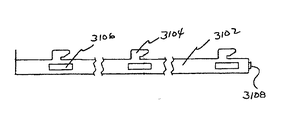
器具/反射板200は、基部202、エンドプレート204、ランプホルダカバー206、バラストカバー208、器具放出機構210、および器具/反射板200用の枢動部材212を備える。基部202は、凸面202Aおよび凹面202Bを有する。エンドプレート204は、外面204Aおよび内面204Bを有する。基部202の凹面202Bおよびエンドプレート204の内面204Bは、空洞203を形成する。空洞203は、1つ以上のランプ12を受け入れる。ランプは、複数のランプホルダまたはトゥームストーン205によって定位置に担持される。
The instrument /
Shadow BoxTMトリム300は、周囲構造310、枢動部材312、表示面314、係合機構320、およびレンズ330を備える。Shadow BoxTMトリム300の枢動部材312は、Shadow BoxTMトリム300が器具/反射板200の周囲の周りを枢動するように、器具/反射板200の基部202の周囲を可撤的に係合する。図1では、Shadow BoxTMトリム300は、器具/反射板200と開放枢動する関係にあり、器具/反射板200に対して90度の角度で配置されるように図示される。Shadow BoxTMトリム300が、器具/反射板200と閉鎖枢動関係にあるように、枢動部材312の周りを移動することができることは、容易に理解することができる。Shadow BoxTMトリム300は、放出機構220と相互作用する係合機構320によって、器具/反射板200と閉鎖枢動する関係に担持される。
The Shadow Box ™ trim 300 includes a surrounding
図2は、T型格子10と係合される設置装置400から枢動され、設置装置400に対して90度の角度で配置される器具/反射板200を伴う、本開示の照明器具装置100の好ましい実施形態の斜視図である。器具/反射板200および設置装置400は、着脱可能な関係だけでなく枢動関係をも有する。したがって、器具/反射板200は、設置装置400から完全に除去することができるか、または器具/反射板200は、設置装置400と枢動関係にあることができるかのいずれかである。
FIG. 2 shows the
図2に図示する器具/反射板200は、凹側面202Aを示す。器具/反射板200は、ランプホルダカバー206、トゥームストーンホルダ207、バラスト20、電源からバラストへのコネクタ260、バラストからトゥームストーンへのコネクタ270、基部202の凸面202A、バラストカバー208、およびバラストカバー208の中の換気格子209を伴い図示される。
The instrument /
T型格子10と係合される設置装置400が示される。設置装置400は、横部材410A、410B、および縦部材430A、430B(後者は図示せず)を含む。T型格子10の縦部分を係合する、設置装置400の縦部材430A、430Bが図示される。縦部材430A、430Bは、好ましくは、例えばU字形金属といった、角のある材料から成る。特に、図2に示す縦部材430Aは、T型格子10を係合するより小さい側面、およびT型格子10から遠隔にある他方のより小さい側面を伴う、その凹側面を図示する。縦部材430A、430Bは、1つ以上の延在部(図示せず)等、横部材410、410Bを可撤的に係合するために、遠隔端部から1つ以上の延在部を有してもよい。縦部材430A、430Bから突出する延在部は、横部材410A、410B、および縦部材430A、430Bの移動を係止するために、戻り止め(図示せず)を端部の場所422に形成するよう、それぞれの横部材410A、410Bの中に受け入れられるように構成することができる。また、戻り止めから遠隔にある端部は、横部材410A、410B、および縦部材430A、430Bの中に図示する穴412中のねじの使用によって、またはいずれかの他の従来の固定機構によって、T型格子10に固定されてもよい。
An
重要なのは、設置装置400に対する、器具/反射板200のチャネルロック機能である。器具/反射板200は、その周囲の1つの側面から延在する、枢動部材212を有する。枢動部材212は、その両方の先端に、枢動部材212の主要部分より大きな半径寸法を有する、拡張部分を有する。設置装置400は、各横部材410A、410Bの中に、1つ以上のスロット414を有する。スロット414は、より大型部分414Aおよびより小型部分414Bを有する。より大型部分414Aは、枢動部材212の拡張部分を通ってそこで受容するためのものである。枢動部材212が、横部材410A、410Bのより大型部分414Aからより小型部分414Bの中へ押し込まれると、枢動部材212は、枢動部材212の拡張部分が横部材410A、410Bの1つの側面上にくるように、横部材410A、410Bのより小型部分414Bの中に固定され、器具/反射板200を伴う枢動部材212の主要部分は、器具/反射板200が枢動部材212によって包囲されるように、横部材410A、410Bの他方の側面上にくる。また、スロット414の代わりに使用することができる、代替のスロット415が図示される。代替手段が、本開示のチャネルロック機能と同じ機能を行うように利用可能であるか、または利用可能であり得、このような代替手段が本開示によって網羅されることは、当業者によって理解され得る。
What is important is the channel locking function of the instrument /
また、器具/反射板200が表面420上のT型格子10内の定位置に担持されるように、器具放出機構210(図1参照)が設置装置400と可撤的に係合されるよう、枢動部材212の周りを器具/反射板200が枢動することも重要である。
Also, the instrument release mechanism 210 (see FIG. 1) is removably engaged with the
図3は、器具/反射板200、Shadow BoxTMトリム300、および設置装置400を示す、本開示の照明器具装置100の好ましい実施形態の斜視図である。設置装置400は、横部材410および縦部材430と共に図示される。Shadow BoxTMトリム300は、周囲構造310および表示面314と共に図示される。器具/反射板200は、基部202、エンドプレート204、ランプホルダカバー206、バラストカバー208、およびロックバー組立部220を含む。基部202は、複数のトゥームストーン調整スロット232および1つ以上のバラストスロット234を有する。トゥームストーン調整スロット232は、照明器具装置100と共に使用されるランプの長さによって、使用されるランプ長に対応するトゥームストーン調整スロット232を不能にすることができるように、ノックアウトの形態で提供される。したがって、いかなるランプ長またはその組み合わせも、本開示の照明器具装置100と共に使用することができることは、当業者によって理解される。同様に、バラスト調整スロット234は、バラスト固定器具(図5参照)およびバラストクリップ(図示せず)と共に使用するために提供される。バラスト固定器具により、突起部分を有する従来のバラストを、バラストの1つの端部を固定するために、バラスト固定器具の下に滑らせることができる。バラストクリップは、サイズおよび形状にかかわらず、バラスト固定器具、基部202、およびバラストクリップの間で、バラストを固定するためにバラスト調整スロット234およびバラストを摺動自在に係合する。バラストカバー208は、換気格子209を有する。
FIG. 3 is a perspective view of a preferred embodiment of the
図4は、本開示の照明器具装置100と関連付けられる、ハウジングまたは基部202の好ましい実施形態の斜視図である。図4は、いかなるランプおよびいかなるバラストとも共に使用するために適合する、本開示の照明器具装置100の能力を図示する。いかなるランプも適合させる能力は、いかなる場所でもランプを担持するトゥームストーン205(図1参照)を位置させ、長さまたは半径にかかわらず、いかなる寸法のランプも受け入れるための能力に由来する。トゥームストーン調整スロット232A、232AAは、トゥームストーンを最大距離分離して担持し、示す基部202に対して最大の長さのランプを受け入れるために提供される。中間トゥームストーン調整スロット232B、232BBは、トゥームストーンを中間距離離して担持し、示す基部202に対して中間の長さのランプを受け入れるために提供される。トゥームストーン調整スロット232C、232CCは、トゥームストーンを最小距離離して担持し、示す基部202に対して最小の長さのランプを受け入れるために提供される。トゥームストーン調整スロット232が、基部202の幅に及ぶため、トゥームストーン205は、各遠隔組のトゥームストーン205と関連付けられるランプを伴い、基部202に渡っていずれの数でも配置することができる。本開示の照明器具装置100で使用するために適合することができる、ランプの数に関する限定要因は、全てのランプの直径の合計が、それぞれのトゥームストーン調整スロット232の長さより短いことである。バラスト調整スロット234は、トゥームストーン調整スロット232と類似の手法で作動するように、凸面202Aの中に図示される。
FIG. 4 is a perspective view of a preferred embodiment of the housing or
図5は、図4に図示する通り、本開示の照明器具装置100と関連付けられるハウジング202の凹面202Bの好ましい実施形態平面図である。最大長のランプおよび最小長のランプ用のトゥームストーン調整スロット232A、232AA、232C、232CCは、ノックアウトとして図示される。中間長さのランプ用のトゥームストーン調整スロット232B、232BBは図2に図示する通り、トゥームストーンホルダ207によって固定される、トゥームストーン205を受け入れる準備の整ったスロットとして図示される。バラスト調整スロット234は、バラスト固定器具(バラスト調整スロット234と一致する)およびバラストクリップ(図示せず)と共に使用するために提供される。バラスト固定器具により、突起部分を有する従来のバラストを、バラストの1つの端部を固定するために、バラスト固定器具の下に滑らせることができる。バラストクリップは、サイズおよび形状にかかわらず、バラスト固定器具、基部202、およびバラストクリップの間で、バラストを固定するためにバラスト調整スロット234およびバラストを摺動自在に係合する。当業者によって理解される通り、バラストクリップは、バラスト固定器具、基部202、およびバラストクリップとバラストとの可撤性係合をもたらす、いかなる構成でもあることができる。
FIG. 5 is a plan view of a preferred embodiment of the
図6は、本開示の照明器具装置100と関連付けられる、ハウジング202の好ましい実施形態の端面図である。ハウジング202は、ハウジング202の凹部分202Bと共に、ハウジング202の凸部分202Aを眺めるように図示される。図6に図示する先端は、可能な放出機構をより良く図示するように、図8および9に図示する。
FIG. 6 is an end view of a preferred embodiment of the
図5Aは、本開示の照明器具装置と関連付けられる、ハウジング1202の別の好ましい実施形態の背面の平面図である。ハウジング1202は、凹部分1202B、第1の角部分1203、第2の角部分1205、第3の角部分1207、プレーナ部分1209、および平坦部分1211を備える。凹部分1202Bは、その中に複数のトゥームストーン調整スロット1232A、1232AA、1232B、1232BB、1232C、1232CCを有する。プレーナ部分1209は、1つ以上のノックアウト1241を備える。また、プレーナ部分1209は、係合要素用の係合および/または枢動点である、1つ以上のT形隙間1243を備える。さらに、プレーナ部分1209は1つ以上の隙間1245を備える。
FIG. 5A is a plan view of the back of another preferred embodiment of the
図6Aは、本開示の照明器具装置と関連付けられる、ハウジング1202の別の好ましい実施形態の端面図である。ハウジング1202は、凹部分1202B、凸部分1202A、第1の角部分1203、第2の角部分1205、第3の角部分1207、プレーナ部分1209、および平坦部分1211を備える。
FIG. 6A is an end view of another preferred embodiment of a
図7は、本開示の照明器具装置100と関連付けられる、Shadow BoxTMトリム300の好ましい実施形態の平面図である。Shadow BoxTMトリム300は、周囲構造310、表示面314、光開口部330A、枢動部材312A、および係合機構320を備える。
FIG. 7 is a plan view of a preferred embodiment of a Shadow Box TM trim 300 associated with the
Shadow BoxTMトリム300は、道具またはアタッチメント機構なしで、除去し照明器具100に取り付けることができる。いずれのShadow BoxTMトリム300も、別のShadow BoxTMトリム300と容易に入れ替えられる。Shadow BoxTMトリム300は、企業ロゴ、あるいは他のブランド設定または宣伝デザインを描写するように、種々の材料、色、質感、およびデザインから成ることができる、装飾トリムを提供する。Shadow BoxTMトリム300は、必要ではないが、T型格子の上方に持ち上げられることなく除去および交換するために、回転し所定の位置に置かれてもよい。Shadow BoxTMトリム300はまた、間接照明装置用の手段を提供することができる。さらに、Shadow BoxTMトリム300は、いかなる器具との使用にも適合することができる。
The Shadow Box ™ trim 300 can be removed and attached to the
より具体的には、限定するものではないが、Shadow BoxTMトリム300は、簡素で、デザインを持ち、絵を持ち、ロゴを持ち、特定のブランド設定を持ち、または宣伝を伝達することができ、全ては単純にデザインと称される。Shadow BoxTMトリム300により、その中のデザインを照らすことができる。Shadow BoxTMトリム300中のデザインの照明は、照明器具と関連付けられるランプによって提供することができる。また、Shadow BoxTMトリム300のデザインは、代替光源によって照らすことができる。このような代替光源の例は、限定するものではないが、LED、レーザ、冷陰極デバイス、CFL等である。Shadow BoxTMトリム300のデザインは、異なる色で表示することができる。デザインの彩色は、色付きマイラーフィルム、色付きLED、プリズム等を使用することによって、達成することができる。Shadow BoxTMトリム300は、Shadow BoxTMトリム300を容易に枢動、除去、および交換するように、着脱が容易な係合機構320を有する。
More specifically, but not limited to, the Shadow Box TM Trim 300 is simple, has a design, has a picture, has a logo, has a specific branding, or can convey advertising. , Everything is simply called design. The Shadow Box ™ trim 300 can illuminate the design inside. Illumination of the design in the Shadow Box ™ trim 300 can be provided by a lamp associated with the luminaire. Also, the Shadow Box ™ trim 300 design can be illuminated by alternative light sources. Examples of such alternative light sources include, but are not limited to, LEDs, lasers, cold cathode devices, CFLs, and the like. The design of the Shadow Box ™ trim 300 can be displayed in different colors. Design coloring can be achieved by using colored mylar films, colored LEDs, prisms, and the like. The Shadow Box ™ trim 300 has an
図8は、本開示の照明器具装置100と関連付けられる、ラッチ機構225の好ましい実施形態の斜視図である。
FIG. 8 is a perspective view of a preferred embodiment of a
図9は、本開示の照明器具装置100と関連付けられる、ラッチ機構226の別の好ましい実施形態の斜視図である。
FIG. 9 is a perspective view of another preferred embodiment of a
図10は、本開示の照明器具装置100と関連付けられる、バラストカバー208の好ましい実施形態の斜視図である。バラストカバー208は、いかなるサイズのバラストも覆うことができるような、細長い部材である。バラストカバー208は、ランプホルダ206用のトゥームストーンホルダカバーを受け入れるための、開口ノックアウト208Aを有する。さらに、バラストカバー208は、ランプホルダ206用のトゥームストーンホルダカバーを使用不可にし、その後受け入れるのに使用することができる、閉口ノックアウト208Bを有する。通常、バラストカバー208の端部は閉じている。また、バラストカバー208は、遠隔電源から電力を受け入れるために、開口ノックアウト208A間に開口部を有する。
FIG. 10 is a perspective view of a preferred embodiment of a
図11は、換気格子209によるバラストカバー208からの熱の排出を提供する、本開示の照明器具装置100と関連付けられる、バラストカバー208の好ましい実施形態の斜視図である。バラストカバー208は、ランプホルダ206用のトゥームストーンホルダカバーを受け入れるための、開口ノックアウト208Aを有する。さらに、バラストカバー208は、ランプホルダ206用のトゥームストーンホルダカバーを使用不可にし、その後受け入れるのに使用することができる、閉口ノックアウト208Bを有する。
FIG. 11 is a perspective view of a preferred embodiment of the
図12は、Shadow BoxTMトリム300によるロゴ340の販促使用を図示する、下方から見られるようにT型格子10と係合される、本開示の照明器具装置100の好ましい実施形態の斜視図である。ロゴ340は、Shadow BoxTMトリム300の表示面314の中にある。ロゴ340は、器具/反射板200の中のランプによって明るくすることができるか、または代替として、照明器具装置100中のランプの電源が入っていない時に、ロゴ340が照らされたままであるように、補助手段によって明るくすることができる。
FIG. 12 is a perspective view of a preferred embodiment of the
図13は、Shadow BoxTMトリム300によるデザイン350の販促使用を図示する、下方から見られるようにT型格子10と係合される、本開示の照明器具装置100の好ましい実施形態の斜視図である。デザイン350は、Shadow BoxTMトリム300の表示面314の中にある。デザイン350は、器具/反射板200の中のランプによって明るくすることができるか、または代替として、照明器具装置100中のランプの電源が入っていない時に、デザイン350が照らされたままであるように、補助手段によって明るくすることができる。
FIG. 13 is a perspective view of a preferred embodiment of the
図14は、本開示によって実践される通り、照明器具を設置する方法の好ましい実施形態を図示するフローチャートである。隙間が周囲によって画定される、天井、壁、またはボックスの中の隙間に、本開示によって実践される通りの照明器具を設置する方法は、設置装置を隙間の周囲と係合するステップと、設置装置と垂下関係で器具を係合するステップと、電源を器具に接続するステップと、器具が隙間の周囲と共に作動するまで、垂れ下がっている器具を回転させるステップと、隙間の周囲と作動関係に器具を固定するステップと、器具を明るくするために器具に電力を提供するステップとを含む。 FIG. 14 is a flowchart illustrating a preferred embodiment of a method for installing a luminaire, as practiced by the present disclosure. A method of installing a luminaire as practiced by the present disclosure in a gap in a ceiling, wall, or box where the gap is defined by the perimeter includes the steps of engaging the installation device with the perimeter of the gap, and installation Engaging the instrument in a drooping relationship with the device; connecting a power source to the instrument; rotating the hanging instrument until the instrument operates with the periphery of the gap; and the instrument in working relationship with the periphery of the gap. And securing power to the instrument to lighten the instrument.
図15は、本開示によって実践される通り、照明器具の中のランプを変える方法の好ましい実施形態を図示するフローチャートである。照明器具がトリム部材によって枢動関係で係合される、本開示によって実践される通りの、照明器具の中のランプを変える方法は、ランプ空洞を暴露するようにトリム部材を器具から係脱させるステップと、器具の中の空洞内のランプが暴露され、トリム部材が器具の一部分から垂れ下がるように、器具から離れてトリム部材を枢動させるステップと、旧式のランプを空洞から除去するステップと、いずれの他のランプまたは構成要素を移動させることなく、空洞の中に新しいランプを係合するステップと、空洞の中にランプを固定するためにトリム部材を枢動させるステップと、トリム部材を器具に固定するためにラッチ機構を係合するステップとを含む。 FIG. 15 is a flowchart illustrating a preferred embodiment of a method for changing a lamp in a luminaire as practiced by the present disclosure. A method of changing a lamp in a luminaire, as practiced by the present disclosure, in which the luminaire is pivotally engaged by a trim member, disengages the trim member from the fixture to expose the lamp cavity. Pivoting the trim member away from the instrument such that the lamp in the cavity in the instrument is exposed and the trim member depends from a portion of the instrument; removing the old lamp from the cavity; Engaging the new lamp into the cavity without moving any other lamp or component, pivoting the trim member to secure the lamp in the cavity, and removing the trim member from the instrument Engaging a latching mechanism to secure to.
図16は、本開示によって実践される通り、バラストを変える方法の好ましい実施形態を図示するフローチャートを示す。照明器具が枢動関係で設置装置と係合される、本開示によって実践される通りの照明器具の中のバラストを変える方法は、器具と設置装置との間でラッチ機構を係脱するステップと、バラスト領域を暴露するように、設置装置から離れて器具を枢動させるステップと、旧式のバラストを器具から除去するステップと、器具上に新しいバラストを係合するステップと、設置装置との係合のために器具を枢動させるステップと、器具を設置装置に固定するステップとを含む。 FIG. 16 shows a flowchart illustrating a preferred embodiment of a method for changing ballast, as practiced by the present disclosure. A method of changing a ballast in a lighting fixture as practiced by the present disclosure in which the lighting fixture is engaged with the installation device in a pivotal relationship includes disengaging a latch mechanism between the fixture and the installation device; The steps of pivoting the instrument away from the installation device to expose the ballast area, removing the old ballast from the instrument, engaging the new ballast on the instrument, and the installation device. Pivoting the instrument for alignment and securing the instrument to the installation device.
図17は、本開示によって実践される通り、異なる長さを有するランプを変えるために、器具に対してトゥームストーンホルダの場所を変える方法の好ましい実施形態を図示するフローチャートである。異なる長さを有するランプを変えるために、器具に対してトゥームストーンホルダの場所を変える方法は、トゥームストーンホルダにアクセスするステップと、器具のハウジングからトゥームストーンホルダを放出するステップと、トゥームストーンホルダを別の場所に再配置するステップと、新しい場所でトゥームストーンホルダを器具のハウジングに固定するステップとを含む。 FIG. 17 is a flow chart illustrating a preferred embodiment of a method for changing the location of the tombstone holder relative to the instrument to change lamps having different lengths as practiced by the present disclosure. A method of changing the location of a tombstone holder relative to an instrument to change a lamp having a different length includes accessing the tombstone holder, releasing the tombstone holder from the housing of the instrument, and the tombstone holder Relocating to a different location and securing the tombstone holder to the instrument housing at the new location.
図18は、本開示によって実践される通り、照明器具付きのShadow BoxTMトリムまたはトリム部材を使用する方法の好ましい実施形態を図示するフローチャートである。照明器具がトリム部材によって枢動関係で係合される、本開示によって実践される通りの、照明器具付きのShadow BoxTMトリムまたはトリム部材を使用する方法は、器具とトリム部材との間でラッチ機構を係脱し、そのラッチ機構が、トリム部材を器具に可撤的に固定するステップと、トリム部材が器具の一部分から垂れ下がるように、器具から離れてトリム部材を枢動させるステップと、トリム部材を器具から除去するステップと、新しいトリム部材を器具と係合するステップと、器具を可撤的に係合するためにトリム部材を枢動させるステップと、トリム部材を器具に固定するためにラッチ機構を係合するステップとを含む。 FIG. 18 is a flow chart illustrating a preferred embodiment of a method of using a Shadow Box ™ trim or trim member with lighting fixture as practiced by the present disclosure. A method of using a Shadow Box TM trim or trim member with a luminaire, as practiced by the present disclosure, in which the luminaire is pivotally engaged by the trim member, latches between the fixture and the trim member. Disengaging the mechanism, the latching mechanism removably securing the trim member to the instrument, pivoting the trim member away from the instrument such that the trim member depends from a portion of the instrument, and the trim member Removing from the instrument, engaging a new trim member with the instrument, pivoting the trim member to removably engage the instrument, and latching to secure the trim member to the instrument Engaging the mechanism.
図19は、本開示によって実践される通り、T型格子の中に設置装置を設置する方法の好ましい実施形態を図示するフローチャートである。本開示によって実践される通り、T型格子の中に設置装置を設置する方法は、T型格子の第1の横側面と一致して第1の横部材を係合するステップと、T型格子の第2の横側面と一致して第2の横部材を係合するステップと、T型格子の第1の縦側面と一致して第1の縦部材を係合するステップと、第1の横部材および第1の縦部材を連動させるステップと、第2の横部材および第1の縦部材を連動させるステップと、T型格子の第2の縦側面と一致して第2の縦部材を係合するステップと、第1の横部材および第2の縦部材を連動させるステップと、横部材および縦部材が設置装置を画定するように、第2の横部材および第2の縦部材を連動させるステップとを含む。 FIG. 19 is a flowchart illustrating a preferred embodiment of a method for installing an installation device in a T-grating as practiced by the present disclosure. As practiced by the present disclosure, a method for installing an installation device in a T-shaped grid includes engaging a first transverse member in alignment with a first lateral side of the T-shaped grid; Engaging the second transverse member in coincidence with the second transverse side of the first, engaging the first longitudinal member in coincidence with the first longitudinal side of the T-lattice, A step of interlocking the transverse member and the first longitudinal member, a step of interlocking the second transverse member and the first longitudinal member, and a second longitudinal member corresponding to the second longitudinal side surface of the T-shaped lattice. Engaging the first transverse member and the second longitudinal member, and interlocking the second transverse member and the second longitudinal member such that the transverse member and the longitudinal member define an installation device. And a step of causing.
図20は、本開示によって実践される通り、ランプ構成またはランプ数量を変える方法の好ましい実施形態を図示するフローチャートである。ランプ構成またはランプ数量を変える方法は、トゥームストーンホルダにアクセスするステップと、トゥームストーンホルダを器具のハウジングから放出するステップと、新しいトゥームストーンホルダを所望の数のトゥームストーンと係合するステップと、新しいトゥームストーンホルダを器具のハウジングに固定するステップとを含む。 FIG. 20 is a flowchart illustrating a preferred embodiment of a method for changing lamp configuration or lamp quantity, as practiced by the present disclosure. A method of changing a lamp configuration or lamp quantity includes: accessing a tombstone holder; releasing the tombstone holder from the housing of the instrument; engaging a new tombstone holder with a desired number of tombstones; Securing a new tombstone holder to the housing of the instrument.
図21は、本開示によって実践される通り、ランプタイプを変える方法の好ましい実施形態を図示するフローチャートである。ランプタイプを変更する方法は、トゥームストーンホルダにアクセスするステップと、トゥームストーンホルダを器具のハウジングから放出するステップと、既存のトゥームストーンを除去するステップと、トゥームストーンホルダの中で新しいランプタイプと共に使用するための新しいトゥームストーンを係合するステップと、トゥームストーンホルダを器具のハウジングに固定するステップとを含む。 FIG. 21 is a flowchart illustrating a preferred embodiment of a method for changing lamp types as practiced by the present disclosure. The method of changing the lamp type includes accessing the tombstone holder, releasing the tombstone holder from the housing of the instrument, removing the existing tombstone, and a new lamp type in the tombstone holder. Engaging a new tombstone for use and securing the tombstone holder to the housing of the instrument.
図22は、本開示によって実践される通り、照明器具延在部を使用する方法の好ましい実施形態を図示するフローチャートである。隙間が周囲によって画定される、天井、壁、またはボックスの隙間の中への移動のために、本開示によって実践される通り、照明器具延在部を使用する方法は、トリム部材を器具から除去するステップと、設置装置から器具と設置装置との間のラッチ機構を介して器具を係脱するステップと、既存の金物類を除去するステップと、金物類を器具延在部上へと置き換えるステップと、器具延在部への器具を正しい対応位置に取り付けるステップと、エンドプレート延在部をエンドプレートに追加するステップと、器具と設置装置との間のラッチ機構を介して設置装置の中への係合のために器具を置き換えるステップと、トリム部材を置き換え、定位置に係止するステップとを含む。 FIG. 22 is a flowchart illustrating a preferred embodiment of a method of using a luminaire extension, as practiced by the present disclosure. As practiced by the present disclosure for movement into a ceiling, wall, or box gap where the gap is defined by the perimeter, the method of using a luminaire extension removes the trim member from the fixture. Detaching the instrument from the installation device via a latch mechanism between the instrument and the installation device, removing the existing hardware, and replacing the hardware on the instrument extension. Attaching the instrument to the instrument extension in the correct corresponding position, adding the end plate extension to the end plate, and into the installation device via a latch mechanism between the instrument and the installation device. Replacing the instrument for engagement, and replacing the trim member and locking it in place.
図23は、本開示によって実践される通り、設置装置延在部を使用する方法の好ましい実施形態を図示するフローチャートである。隙間が周囲によって画定される、天井、壁、またはボックスの隙間の中への移動のために、本開示によって実践される通り、設置装置延在部を使用する方法は、器具を設置装置から除去するステップと、設置装置を開口部から除去し、延在部を設置装置に取り付けるステップと、天井または壁の空洞の中に設置装置を置き換えるステップと、器具を置き換え、器具と設置装置との間のラッチ機構を介して設置装置の中に係合するステップとを含む。 FIG. 23 is a flowchart illustrating a preferred embodiment of a method of using an installation device extension, as practiced by the present disclosure. As practiced by this disclosure for movement into a ceiling, wall, or box gap where the gap is defined by the perimeter, the method of using the installation device extension removes the instrument from the installation device. Removing the installation device from the opening and attaching the extension to the installation device; replacing the installation device in a ceiling or wall cavity; and replacing the appliance between the appliance and the installation device. Engaging into the installation device via a latching mechanism.
図24は、間接光を向けるために、本開示によって実践される通り、照明器具を適合させる方法の好ましい実施形態を図示するフローチャートである。間接光を向けるために、本開示によって実践される通り、照明器具を適合させる方法は、トリム部材を除去するステップと、ランプを除去するステップと、器具を設置装置から下げるステップと、電子機器を除去するステップと、新しい電子機器を追加するステップと、器具を設置装置の中に戻して回転させるステップと、器具を設置装置の中に固定するステップと、間接反射シールドを設置するステップと、ランプを追加するステップと、間接装置をトリム部材に取り付けるステップと、トリム部材を器具に取り付けるステップと、トリム部材を器具の中で回転させ、定位置に固定するステップとを含む。 FIG. 24 is a flowchart illustrating a preferred embodiment of a method for adapting a luminaire as practiced by the present disclosure to direct indirect light. As practiced by the present disclosure for directing indirect light, a method of adapting a luminaire includes removing a trim member, removing a lamp, lowering the fixture from an installation device, and electronic equipment. Removing, adding new electronics, rotating the instrument back into the installation apparatus, securing the apparatus into the installation apparatus, installing an indirect reflective shield, and a lamp Adding the indirect device to the trim member, attaching the trim member to the instrument, and rotating the trim member in the instrument to lock it in place.
図25A、25B、25C、25Dは、本開示の照明器具装置100と共に使用するための、間接照明トリム500の好ましい実施形態の斜視図である。図25A、25B、25C、25Dは、本開示の照明器具装置100を間接照明器具に変更するための、間接照明トリム500を図示する。トゥームストーンホルダ延在部516Aは、所望のランプ長スロット232B、232BB(図4参照)の中に挿入され、ランプ12を器具/反射板200(図1参照)内の所望の高さに位置付けることを可能にする。ランプホルダ205は、トゥームストーンホルダ延在部カバー516が取り付けられる前に、トゥームストーンホルダ延在部516Aの中に挿入される。間接照明トリム500は、Shadow BoxTMトリム300上に配置され、クリップデバイス352と定位置で固定される。間接反射シールド580は、Shadow BoxTMトリム300を閉じ、間接照明トリム500を取り付ける前に、器具/反射板200の中に挿入され、定位置に固定される。
25A, 25B, 25C, 25D are perspective views of a preferred embodiment of an
図26は、本開示のバラストレール2200の好ましい実施形態の斜視図である。バラストレール2200は、平面部分2202、オフセット部分2204、縁部分2206、および傾斜部分2208を備える。平面部分2202は、バラストをバラストレール2200に可撤的に固定するために、1つ以上のバラスト調整スロット2234A、2234Bを有する。
FIG. 26 is a perspective view of a preferred embodiment of the
図27は、図26に図示する通りの、本開示のバラストレール2200の好ましい実施形態の端面図である。バラストレール2200は、平面部分2202、オフセット部分2204および縁部分2206、ならびに傾斜部分2208を有する。
FIG. 27 is an end view of a preferred embodiment of the
図28は、図26に図示する通りの、本開示のバラストレール2200の好ましい実施形態の縦断図である。
FIG. 28 is a longitudinal view of a preferred embodiment of the
図29は、コレットと係合された、図26に図示する通りの、本開示のバラストレール2200の好ましい実施形態の平面図である。バラストレール2200は、平面部分2202、オフセット部分2204、縁部分2206、および傾斜部分2208を備える。平面部分2202は、バラストをバラストレール2200に可撤的に固定するために、1つ以上のバラスト調整スロット2234A、2234Bを有する。また、コレット2240は、バラストレール2200をハウジングに固定する。図26、27、28、29、30に図示する構成により、バラストレール2200に取り付けられたバラストに、特別かつ強化されたヒートシンク効果を提供する。
FIG. 29 is a plan view of a preferred embodiment of the
図30は、図29に図示する通りの、本開示のコレット2240の好ましい実施形態の平面図である。コレット2240は、平面部材2242、縁部分2246、傾斜部分2248、および1つ以上の隙間2249を備える。
30 is a plan view of a preferred embodiment of the
図31は、本開示のラッチバー3100の好ましい実施形態の斜視図である。ラッチバー3100は、縦部材3102、ラッチ3104、隙間3106、および角部分3108を備える。
FIG. 31 is a perspective view of a preferred embodiment of the latch bar 3100 of the present disclosure. The latch bar 3100 includes a
図31Aは、図31に図示する通りの、本開示のラッチバー3100の好ましい実施形態の縦断図である。ラッチバー3100は、角部分3108と共に図示される。
FIG. 31A is a longitudinal view of a preferred embodiment of the latch bar 3100 of the present disclosure, as illustrated in FIG. Latch bar 3100 is illustrated with
図31Bは、図31Aに図示する通りの、本開示のラッチバー3100の角部分3108の好ましい実施形態の詳細図である。
FIG. 31B is a detailed view of a preferred embodiment of the
図31Cは、図31に図示する通りの、本開示のラッチバー3100の好ましい実施形態の縦破断図である。ラッチバー3100は、縦部材3102、ラッチ3104、隙間3106、および角部分3108と共に図示される。
FIG. 31C is a longitudinal cutaway view of a preferred embodiment of the latch bar 3100 of the present disclosure, as illustrated in FIG. Latch bar 3100 is illustrated with
図31Dは、図31Aに図示する通りの、本開示のラッチバー3100のラッチの好ましい実施形態の詳細図である。ラッチバー3100は、縦部材3102、ラッチ3104、隙間3106、および角部分3108と共に図示される。
FIG. 31D is a detailed view of a preferred embodiment of the latch of the latch bar 3100 of the present disclosure, as illustrated in FIG. 31A. Latch bar 3100 is illustrated with
図32Aは、本開示のレンズ受取ガイド3200の好ましい実施形態の斜視図である。レンズ受取ガイド3200は、第1の部材3202、第2の部材3204を備え、第1の部材3202および第2の部材3204は、角3203によって分離される。角3203はレンズカバーのコーナーで角と一致し、本実施形態では90度である。第1の部材3202および第2の部材3204は、対応する隙間3211、3111A、3112、3112A、3113、3113Aを有する。各隙間3211、3111A、3112、3112A、3113、3113Aはその中に突起3220を有する。突起3220は、その中にレンズクリップ3300(図33参照)を可撤的に固定するためのものである。
FIG. 32A is a perspective view of a preferred embodiment of a
図32Bは、図32Aに図示する通りの、本開示のレンズ受取ガイド3200の好ましい実施形態の立面図である。レンズ受取ガイド3200は、3つの隙間3211、3112、3113を伴う第1の部材3202を有する。隙間3211、3112、3113の数は、レンズ受取ガイド3200によって収容されるであろう、レンズの厚さによって決定される。図示する実施形態では、3つの隙間3211、3112、3113は、3つの間隙G11、G12、およびG13の厚さを伴うレンズに対応する。
FIG. 32B is an elevation view of a preferred embodiment of the
図32Cは、図32Aに図示する通りの、本開示のレンズ受取ガイド3200の好ましい実施形態の平面図である。
FIG. 32C is a plan view of a preferred embodiment of the
図33Aは、本開示のレンズクリップ3300の好ましい実施形態の斜視図である。レンズクリップ3300は、基部部材3302、側面部材3304、角度のある部材3306、係合部材3308、および押圧部材3310を備える。側面部材3304は、例えば、円形または四角といったいかなる形状でもあり得る。角度のある部材3306は、その中に隙間3312を有する。レンズクリップ3300の角度のある部材3306中の隙間3312は、レンズクリップ3300がレンズ受取ガイド3200の隙間3211の中に係合される時、隙間3211の中に突起3220を受容するためのものである。レンズクリップ3300は、レンズを固定するために挿入され、レンズを変えるために除去される。
FIG. 33A is a perspective view of a preferred embodiment of a
図33Bは、図33Aに図示する通りの、本開示のレンズクリップの好ましい実施形態の立面図である。 FIG. 33B is an elevation view of a preferred embodiment of the lens clip of the present disclosure, as illustrated in FIG. 33A.
モジュール式殺菌挿入部
チャンバ4200、紫外(UV)光源4300、および空気発動機4400を有する筺体4100を備える、モジュール式殺菌挿入部4000が提供される。モジュール式殺菌挿入部4000は、照明器具100を係合するように適合する。チャンバ4200は、チャンバ4200を通過する空気の混合を提供するように適合する。UV光源4300は、例えば、バクテリア物質内でDNA過程を中断させる等、バクテリア物質を破壊するような波長で提供される。感知デバイス4500は、適切な殺菌効果を判定するために、処理された空気を試験するのに使用することができる。自動遮断部4600は、消費電力用に使用することができる。したがって、空気は、筺体4100の中へ移動し、チャンバ4200内を循環し、UV光源4300によって照射され、妥当な殺菌効果を判定するために感知デバイス4500によって感知され、筺体4100に隣接する領域に放出される。
Modular sterilization insert 4000 A modular sterilization insert 4000 is provided that includes a housing 4100 having a chamber 4200, an ultraviolet (UV) light source 4300, and an air mover 4400. The modular sterilization insert 4000 is adapted to engage the
図34は、本開示のUV殺菌モジュール式挿入部4000の実施形態の斜視図である。 FIG. 34 is a perspective view of an embodiment of a UV sterilization modular insert 4000 of the present disclosure.
図35は、本開示のUV殺菌モジュール式挿入部4000の別の実施形態の斜視図である。 FIG. 35 is a perspective view of another embodiment of the UV sterilization modular insert 4000 of the present disclosure.
図36は、チャンバ4200、バッフル4210、UV光源4300、UVランプ感知デバイス4500を有する筺体4100を図示し、筺体4100は吸気口4102および出口4104を有する、本開示のUV殺菌モジュール式挿入部4000の実施形態の断面図である。UV反射材料4230は、殺菌性UV放射の強度を強化するために、バッフル4210の表面に取り付けられる。 36 illustrates a housing 4100 having a chamber 4200, a baffle 4210, a UV light source 4300, and a UV lamp sensing device 4500, the housing 4100 having an inlet 4102 and an outlet 4104 of the UV sterilization modular insert 4000 of the present disclosure. It is sectional drawing of embodiment. UV reflective material 4230 is attached to the surface of baffle 4210 to enhance the intensity of bactericidal UV radiation.
図37は、チャンバ4200、バッフル4210、UV光源4300、UVランプ感知デバイス4500、吸気口4102、排出口4104、ファンまたは空気発動機4400、カバー板4106、ファングリル4108A、排気口4104、排気グリル4108B、および電力用自動切断スイッチ4112を有する筺体4100を図示する、本開示のUV殺菌モジュール式挿入部4000の好ましい実施形態の断面図である。 FIG. 37 shows a chamber 4200, a baffle 4210, a UV light source 4300, a UV lamp sensing device 4500, an inlet 4102, an outlet 4104, a fan or air motor 4400, a cover plate 4106, a fan grill 4108A, an exhaust outlet 4104, and an exhaust grill 4108B. And FIG. 4 is a cross-sectional view of a preferred embodiment of the UV sterilization modular insert 4000 of the present disclosure illustrating a housing 4100 with an automatic power disconnect switch 4112.
図38は、殺菌効率または相対強度パーセントに対する、ナノメートル単位の波長を図示するグラフである。UV放射は、通常、水銀蒸気、エキシマ、およびより近年のLEDランプによって、人工的に生み出される。253.7の殺菌波長で最も効率の良いランプの放射エネルギーが出され、スペクトルのUVC部としても知られる。図38に見られる通り、ランプは、UVA、UVB、可視光(400nmを上回る波長)、および熱を含む、二次電子放出を有する。UVC反射特性を伴う反射材料4230は、UV殺菌ランプのUV効率を増すように使用される。本殺菌器具および挿入部と共に使用可能な、種々のタイプのUVCランプがある。ランプの例には、冷陰極殺菌UVランプ、熱陰極殺菌UVランプ、薄型殺菌紫外線ランプ、高出力殺菌UVランプ、UV発光ダイオードまたはUV LEDランプ、およびエキシマUVランプがある。 FIG. 38 is a graph illustrating wavelengths in nanometers versus bactericidal efficiency or relative intensity percentage. UV radiation is usually produced artificially by mercury vapor, excimer, and more recent LED lamps. The most efficient lamp radiant energy is produced at a germicidal wavelength of 253.7, also known as the UVC part of the spectrum. As seen in FIG. 38, the lamp has secondary electron emission, including UVA, UVB, visible light (wavelengths above 400 nm), and heat. Reflective material 4230 with UVC reflective properties is used to increase the UV efficiency of the UV germicidal lamp. There are various types of UVC lamps that can be used with the present sterilization instrument and insert. Examples of lamps include cold cathode germicidal UV lamps, hot cathode germicidal UV lamps, thin germicidal UV lamps, high power germicidal UV lamps, UV light emitting diodes or UV LED lamps, and excimer UV lamps.
図39は、UV放射を使用する細菌の根絶を図示する図である。殺菌性紫外線(UVC)は、DNAを損傷させることによって細胞を殺す。光は、DNAを形成する塩基のうちの1つである、チミンの2つの分子間で反応を惹起する。この波長(短波UVまたはUVC)でのUV光により、DNA上の隣接するチミン分子を二量体化させる。その結果生じるチミン二量体は、非常に安定している。これらの欠損が微生物のDNA上に十分蓄積される場合、その複製が阻害され、それによってDNAを無害にする。さらに、UV光子により、異なる手段で生体のDNA分子に害を与える。例えば、隣接する塩基は、「はしご」に渡って結合する代わりに、互いに結合する。これによりバルジが作成され、歪んだDNA分子は適切に機能しなくなる。UVC光への暴露が長ければ長いほど、より多くのチミン二量体がDNAの中に形成される。細胞過程がDNA損傷によって中断する場合、細胞はその通常の機能を実行することができなくなる。損傷が拡大し、広範囲に広がる場合、細胞は死んでしまう。 FIG. 39 is a diagram illustrating the eradication of bacteria using UV radiation. Bactericidal ultraviolet (UVC) kills cells by damaging DNA. Light triggers a reaction between two molecules of thymine, one of the bases that form DNA. UV light at this wavelength (shortwave UV or UVC) dimerizes adjacent thymine molecules on the DNA. The resulting thymine dimer is very stable. If these defects accumulate well on the microbial DNA, their replication is inhibited, thereby rendering the DNA harmless. In addition, UV photons harm biological DNA molecules by different means. For example, adjacent bases bind to each other instead of binding across a “ladder”. This creates a bulge and distorted DNA molecules do not function properly. The longer the exposure to UVC light, the more thymine dimers are formed in the DNA. If a cellular process is interrupted by DNA damage, the cell will not be able to perform its normal function. If the damage spreads and spreads extensively, the cells die.
例えば、空気の流れ、湿度、微生物のUV光までの距離、および照射時間といった多くの変形例によって、効果的なUV量の計算がもたらされる。しかしながら、UV光が、十分なUV量を与えると、いかなるDNAを基とする微生物をも殺すことは、当該分野では既知である。UV光は、累積するごとにDNAを破壊する。それゆえ、空気がUV光源4300を含有するチャンバ4200を通って循環すると、UV光は継続的に空気を殺菌する。微生物がチャンバ4200を通る第1の経路上で効果的に非活性化されない場合、UV光は、続く経路上でDNAを破壊し続けるであろう。UV殺菌器具または挿入部では、微生物が移動する動的環境にあることが必要である。微生物は、制御されていない場合、急速に増える。UV殺菌器具または挿入部は、浮遊微生物を屋内環境から減少させることを支援する。 For example, many variations such as air flow, humidity, microbial distance to UV light, and irradiation time result in an effective UV dose calculation. However, it is known in the art that UV light kills any DNA-based microorganisms when it provides a sufficient UV dose. Every time UV light accumulates, it destroys DNA. Therefore, as the air circulates through the chamber 4200 containing the UV light source 4300, the UV light continuously sterilizes the air. If the microorganism is not effectively deactivated on the first path through chamber 4200, the UV light will continue to destroy the DNA on the subsequent path. UV sterilizers or inserts need to be in a dynamic environment where microorganisms move. Microorganisms grow rapidly if not controlled. UV sterilizers or inserts help reduce airborne microorganisms from the indoor environment.
本開示は、異なる設計のUV殺菌器具、追加ボックス、またはアタッチメントを提供する。具体的には、端部キャップまたは追加ボックスの設計、バラストカバーまたはアタッチメントの設計、内部設計および遠隔設計など、いくつかの一般的な設計が使用可能である。 The present disclosure provides different designs of UV sterilization instruments, additional boxes, or attachments. In particular, several common designs are available, such as end cap or additional box designs, ballast cover or attachment designs, internal designs and remote designs.
図40は、端部キャップまたは追加ボックスの設計を図示する。ボックスの設計は、他のデバイスと関連させて使用するか、または独立型デバイスとして使用することができる。図40は、蛍光灯器具100と共に使用するために適合した、本開示のUV殺菌モジュール式追加ボックス器具5000の別の好ましい実施形態の斜視図である。図40は、追加ボックス殺菌器具5000を図示する。追加ボックス殺菌器具5000は、照明器具100に取り付けられる。追加ボックス殺菌器具5000は、照明器具100の片方または両方の先端に追加することができる。追加ボックス殺菌器具5000が、外部ケーシング5002付きで図示される。
FIG. 40 illustrates an end cap or additional box design. The box design can be used in conjunction with other devices or as a stand-alone device. 40 is a perspective view of another preferred embodiment of the UV disinfection modular add-on
図41は、図40に示す通りの、本開示のUV殺菌モジュール式追加ボックス殺菌器具5000の好ましい実施形態の斜視図である。図41は、フロー組立部5100および光組立部5200を図示する、追加ボックス殺菌器具5000の斜視図である。フロー組立部5100は、空気発動機5102、入口チャンバ5103、バッフル5104、照射チャンバ5106、第2のバッフル5108、および出口チャンバ5110を含む。フロー組立部5100は、追加ボックス器具5000の中に空気の特定の流量をもたらすように、空気発動機またはファン5102を提供する。空気発動機5102により、空気の流れは入口チャンバ5103の中へ進み、バッフル5104によってそらすことができる。妨げられた空気は、乱気流状態で照射チャンバ5106に入る。妨げられた空気は、乱気流が維持されるように、4000を上回る十分に高いレイノルズ数を有する。必要ではないが、4000を上回るレイノルズ数を有する乱気流状態により、照射物質の効果の強化が提供される。さらに、照射チャンバ5106のサイズは、照射されている特定の殺菌性の物質の滞留時間と比例するように提供される。したがって、例えば、その物質の破壊のために、特定の殺菌性の物質を照射する時間が、より長い滞留時間を必要とする場合、チャンバのサイズを修正することができる。同様に、空気発動機5102の流量も、空気の流れを増加または減少するように変更することができる。限定するものではないが、重要な変数は、滞留時間、流量、UV強度、および乱気流の状態である。
41 is a perspective view of a preferred embodiment of the UV sterilization modular add-on sterilizer 5000 of the present disclosure as shown in FIG. FIG. 41 is a perspective view of an
バッフル5104、5108により、照射チャンバ5106内のUV光はチャンバ内に含有することができる。センサ5300は、複数の目的のために提供される。第1に、センサ5300は、照射チャンバ5106内でUV光の強度を測定するために提供される。光が外に出るか、または特定の強度内ではない場合、信号が、殺菌器具5000に対してメンテナンスが必要であると示す。また、センサ5300は、殺菌性の物質が照射チャンバ5106内にある間、達成された低下の指標を提供するために、照射チャンバ5106内で殺菌性の物質を試験するように使用することができる。空気の流れは再び、第2のバッフル5108によって妨げられる。第2のバッフル5108はまた、照射チャンバ5106内の乱気流の源である。空気の流れは、第2のバッフル5108の周囲を通り、出口チャンバ5110の中へと進む。光組立部5200は、取付具5202およびUVランプ5204を備える。UVランプと共に使用するために適合可能ないかなる光組立部も、本開示で使用可能であろうことは、当業者によって理解することができる。また、フロー組立部5100は、反射性の効率を増加させ、それによってUV殺菌器具5000の有効性を増加させるように、反射性表面、抗菌性表面、またはそれらの組み合わせで被覆されてもよい。
The
図42は、図40および41に図示する通りの、本開示のUV殺菌モジュール式追加ボックスの好ましい実施形態の立面図である。図42は、図41に図示する追加ボックス殺菌器具5000の立面断面図である。空気発動機またはファン5102は、入口チャンバ5103の中に殺菌性の物質を持ち込む空気の入口に提供される。入口チャンバ5103は、殺菌性の物質が照射チャンバ5106に進入する前に、バッフル5104によって強化された乱気流を提供する。照射チャンバ5106では、殺菌性の物質は、殺菌性の物質の所望の消毒を達成するため、殺菌性の物質の所望の低下を達成するように、十分な滞留時間で含有される。消毒された殺菌性の物質は、バッフル5108周辺の照射チャンバ5106から、出口チャンバ5110の中へと通過する。処理された殺菌性の物質は、出口ポート5112を介してチャンバ5110から出る。UVランプ5204を支持する、取付具5202が図示される。ケーシング5002によって、フロー組立部5100および光組立部5200は封入されることができる。
42 is an elevation view of a preferred embodiment of the UV disinfection modular add-on box of the present disclosure as illustrated in FIGS. 40 and 41. FIG. 42 is an elevational cross-sectional view of the
図43は、バラストカバーまたはアタッチメント設計を図示する。図43は、蛍光灯器具と共に使用するために適合した、本開示のUV殺菌モジュール式アタッチメントの別の好ましい実施形態の断面斜視図である。さらに、本開示のUV殺菌モジュール式アタッチメントは、独立型装置として使用することができる。 FIG. 43 illustrates a ballast cover or attachment design. FIG. 43 is a cross-sectional perspective view of another preferred embodiment of the UV sterilization modular attachment of the present disclosure adapted for use with a fluorescent light fixture. Furthermore, the UV sterilization modular attachment of the present disclosure can be used as a stand-alone device.
図44は、図43に図示する通りの、本開示のUV殺菌モジュール式アタッチメントの好ましい実施形態の上面断面図である。図44は、本開示の付着UV殺菌器具6000の断面斜視図を図示する。付着殺菌器具6000は、フロー組立部6100および光組立部6200を備える。フロー組立部6100は、第1の照射チャンバ6103、第1のバッフル6101、第2の照射チャンバ6104、第2のバッフル6102、第3の照射チャンバ6105、第3のバッフル6103、第4の照射チャンバ6106、第4のバッフル6104、第5の照射チャンバ6107、および第5のバッフル6105を備える。光組立部6200は、第1のUV照射器6210、第2のUV照射器6211、第3のUV照射器6212、および第4のUV照射器6213を備える。それぞれの照射器には、支持部およびUV光エミッタが提供される。また、付着殺菌器具6000は、2つのファンとして図示される、空気発動機6102を備える。さらに、取り付けられた殺菌器具6000は、フロー組立部6100および光組立部6200を封入するためのケース6002を有する。また、フロー組立部6100は、反射性の効率を増加させ、それによって付着UV殺菌器具6000の有効性を増加させるように、反射性表面、抗菌性表面またはそれらの組み合わせで被覆されてもよい。
FIG. 44 is a top cross-sectional view of a preferred embodiment of the UV sterilization modular attachment of the present disclosure as illustrated in FIG. FIG. 44 illustrates a cross-sectional perspective view of the
図45は、図43および44に図示する通りの、本開示のUV殺菌モジュール式アタッチメントの斜視図である。図45は、付着殺菌器具6000および追加ボックス殺菌器具5000と関連付けられる、器具100を図示する。
45 is a perspective view of the UV sterilization modular attachment of the present disclosure as illustrated in FIGS. 43 and 44. FIG. FIG. 45 illustrates the
図46は、図43、44、および45に図示する通りの、本開示のUV殺菌モジュール式アタッチメントの端面図である。図46は、器具100と関連する追加ボックス殺菌器具5000および付着殺菌器具6000を伴う端面図である。
FIG. 46 is an end view of the UV sterilization modular attachment of the present disclosure, as illustrated in FIGS. 43, 44, and 45. 46 is an end view with an additional
さらなる利点及び変形が、当業者には容易に生じるであろう。それゆえ、そのより広い側面における本開示は、特定の詳細、代表的な装置、および本明細書に示し記載する例示的実施例に限定されない。したがって、開示する一般的な発明概念の精神または範囲から逸脱することなく、詳細から新たな試みが生み出される場合がある。 Additional advantages and modifications will readily occur to those skilled in the art. Thus, the disclosure in its broader aspects is not limited to the specific details, representative apparatus, and illustrative examples shown and described herein. Accordingly, new attempts may be made from the details without departing from the spirit or scope of the disclosed general inventive concept.
Claims (11)
前記殺菌灯キットは、筺体、空気誘導用組立部およびUV照射用組立部を備え、
前記吊り下げ式格子天井は、1つの平面を備え、
前記反射板照明器具は、
少なくとも2つの長手方向に配置されたエンドプレート、1つの凹内面および1つの凸外面を備える細長いハウジングであって、前記凹内面は、複数の側面を有する周囲で空洞を画定し、前記空洞内に1つ以上のランプを受容するための、細長いハウジングと、
前記空洞を封入するための前記細長いハウジングと係合するためのトリム部材であって、前記トリム部材は、前記細長いハウジングの前記凹内面の前記周囲と係合され、および前記トリム部材は、前記細長いハウジングの長手方向に沿って、前記少なくとも2つのエンドプレートを超えて延在して突起部を形成し、前記突起部は、突起部を貫通する少なくとも1つの隙間を有する、トリム部材と、
前記細長いハウジングの前記凸外面に隣接して支持されるバラストレールであって、前記バラストレールは、1つのバラストを受容し、前記細長いハウジングから離れた前記バラストと、前記ハウジングによって形成された前記空洞の外側とを支持することにより、前記バラストレールと前記バラストとが、前記細長いハウジングおよび前記空洞の外側で係合されている、バラストレールと、および
前記反射板照明器具を、前記細長いハウジングの前記周囲の側面のうちの1つについて枢動関係で、前記吊り下げ式格子天井に装着させる枢動部材であって、且つ前記反射板照明器具の作動中に前記吊り下げ式格子天井と同じ平面に、前記反射板照明器具が存在する第1の枢動位置と、暴露された前記バラストと共に、前記吊り下げ式格子天井から90°移動して、前記周囲の前記側面のうちの1つから枢動された前記反射板照明器具が存在する第2の枢動位置とを有する枢動部材と、を備えており、
前記殺菌灯キットの前記筺体は、前記トリム部材の前記突起部と係合することにより、流動する空気が前記空気誘導用組立部に取り込まれ、前記トリム部材の前記少なくとも1つの隙間を通って排出される、殺菌灯器具。 A germicidal lamp fixture comprising a reflector luminaire engaged with a suspended grid ceiling and at least one germicidal lamp kit,
The germicidal lamp kit comprises a housing, an air guiding assembly and a UV irradiation assembly,
The suspended grid ceiling comprises one plane,
The reflector luminaire is
An elongate housing comprising at least two longitudinally arranged end plates, a concave inner surface and a convex outer surface, the concave inner surface defining a cavity having a plurality of sides and within the cavity An elongated housing for receiving one or more lamps;
A trim member for engaging the elongated housing for enclosing the cavity, wherein the trim member is engaged with the periphery of the concave inner surface of the elongated housing, and the trim member is the elongated member. A trim member extending along the longitudinal direction of the housing beyond the at least two end plates to form a protrusion, the protrusion having at least one gap extending through the protrusion; and
A ballast rail supported adjacent to the convex outer surface of the elongated housing, the ballast rail receiving one ballast and spaced from the elongated housing, and the cavity formed by the housing The ballast rail and the ballast are engaged on the outside of the elongated housing and the cavity, and the reflector illuminator is disposed on the elongated housing. A pivoting member that is pivotally connected to one of the surrounding side surfaces and mounted on the suspended grid ceiling, and is flush with the suspended grid ceiling during operation of the reflector luminaire. The suspended grid ceiling with a first pivot position where the reflector luminaire is present and the exposed ballast A pivot member having a second pivot position where the reflector luminaire is pivoted from one of the surrounding side surfaces and is moved 90 ° from
The housing of the germicidal lamp kit engages with the protrusion of the trim member, so that flowing air is taken into the air guiding assembly and is discharged through the at least one gap of the trim member. A germicidal lamp fixture.
前記筺体は、
空気誘導のための、筺体内部にある組立部であって、該組立部は、空気流動装置、入口チャンバ、少なくとも1つのバッフル、照射チャンバ、および出口チャンバを備え組立部を通って空気を移動させるための組立部と、および
前記照射チャンバと関連して作動するUV光を照射するための、筺体内部にある組立部と、を備え、
前記吊り下げ式格子天井は1つの平面を備え、および、
前記反射板照明器具は、
少なくとも1つの凹内面および凸外面を備える細長いハウジングであって、前記凹内面は空洞を画定し、前記細長いハウジングは、前記空洞内に1つ以上のランプを受容するための、細長いハウジングと、
前記細長いハウジングの前記凸外面に隣接して支持されるバラストレールであって、前記バラストレールは、1つのバラストを受容し、前記細長いハウジングから離れた前記バラストと、前記ハウジングによって形成された前記空洞の外側とを支持することにより、前記バラストレールと前記バラストとが、前記細長いハウジングおよび前記空洞の外側で係合されている、バラストレールと、および
前記反射板照明器具を、前記細長いハウジングの周囲の側面のうちの1つについて枢動関係で、前記吊り下げ式格子天井に装着させる枢動部材であって、且つ前記反射板照明器具の作動中に前記吊り下げ式格子天井と同じ平面に、前記反射板照明器具が存在する第1の枢動位置と、暴露された前記バラストと共に、前記吊り下げ式格子天井から90°移動して、前記周囲の前記側面のうちの1つから枢動された前記反射板照明器具とが存在する第2の枢動位置とを有する枢動部材と、を備える、殺菌灯器具。 A germicidal lamp fixture comprising a housing configured to engage with a reflector lighting fixture configured to engage with a suspended grid ceiling,
The housing is
An assembly within a housing for air guidance, the assembly comprising an air flow device, an inlet chamber, at least one baffle, an irradiation chamber, and an outlet chamber for moving air through the assembly An assembly for the interior of the housing for irradiating UV light operating in connection with the irradiation chamber;
Before Symbol hanging lattice ceiling comprises one plane, and,
The reflector luminaire is
An elongate housing comprising at least one concave inner surface and a convex outer surface, wherein the concave inner surface defines a cavity, the elongate housing for receiving one or more lamps in the cavity;
A ballast rail supported adjacent to the convex outer surface of the elongated housing, the ballast rail receiving one ballast and spaced from the elongated housing, and the cavity formed by the housing The ballast rail and the ballast are engaged on the outside of the elongated housing and the cavity, and the reflector illuminator around the elongated housing. A pivoting member that is pivotally mounted on one of the side surfaces of the suspended grid ceiling and in the same plane as the suspended grid ceiling during operation of the reflector luminaire, With the first pivot position where the reflector luminaire is present and the exposed ballast, from the suspended grid ceiling A sterilization lamp fixture comprising: a pivot member having a second pivot position, wherein the reflector illuminator is pivoted from one of the surrounding side surfaces and is moved 90 degrees; .
Applications Claiming Priority (3)
| Application Number | Priority Date | Filing Date | Title |
|---|---|---|---|
| US21668709P | 2009-05-20 | 2009-05-20 | |
| US61/216,687 | 2009-05-20 | ||
| PCT/US2010/001493 WO2010134991A1 (en) | 2009-05-20 | 2010-05-20 | Germicidal fixture and methods |
Publications (3)
| Publication Number | Publication Date |
|---|---|
| JP2012527302A JP2012527302A (en) | 2012-11-08 |
| JP2012527302A5 JP2012527302A5 (en) | 2016-04-28 |
| JP5921429B2 true JP5921429B2 (en) | 2016-05-24 |
Family
ID=43126434
Family Applications (1)
| Application Number | Title | Priority Date | Filing Date |
|---|---|---|---|
| JP2012511825A Active JP5921429B2 (en) | 2009-05-20 | 2010-05-20 | Sterilizer |
Country Status (11)
| Country | Link |
|---|---|
| US (1) | US8350228B2 (en) |
| EP (1) | EP2433048B1 (en) |
| JP (1) | JP5921429B2 (en) |
| KR (2) | KR101586990B1 (en) |
| CN (1) | CN102483214B (en) |
| AU (1) | AU2010250125B2 (en) |
| BR (1) | BRPI1010895B1 (en) |
| CA (1) | CA2762905C (en) |
| MX (1) | MX2011012415A (en) |
| WO (1) | WO2010134991A1 (en) |
| ZA (1) | ZA201109352B (en) |
Families Citing this family (41)
| Publication number | Priority date | Publication date | Assignee | Title |
|---|---|---|---|---|
| US9726388B2 (en) * | 2009-07-20 | 2017-08-08 | Lennox Industries Inc. | Reflective ultraviolet light shield for a HVAC unit |
| EP2529759A1 (en) * | 2011-06-03 | 2012-12-05 | Virobuster GmbH | Apparatus and method for an inactivation of proteinogenic allergens |
| US9093258B2 (en) | 2011-06-08 | 2015-07-28 | Xenex Disinfection Services, Llc | Ultraviolet discharge lamp apparatuses having optical filters which attenuate visible light |
| DE102012008733A1 (en) * | 2012-05-04 | 2013-11-07 | Xylem Water Solutions Herford GmbH | UV water treatment plant with open channel |
| USD765905S1 (en) * | 2012-11-13 | 2016-09-06 | Koller Enterprises, Inc. | Captive latch for a fluorescent lighting fixture |
| CN103446604A (en) * | 2013-08-22 | 2013-12-18 | 苏州康华净化系统工程有限公司 | Sterilization lamp |
| WO2015031785A1 (en) * | 2013-08-30 | 2015-03-05 | American Air & Water, Inc. | Ultraviolet disinfection lighting system |
| US9447949B2 (en) * | 2014-04-25 | 2016-09-20 | Elite Lighting | Light fixture |
| US10517972B2 (en) | 2014-12-09 | 2019-12-31 | Scott D. Usher | Anti-biofouling of submerged lighting fixtures |
| US10436437B1 (en) | 2014-12-09 | 2019-10-08 | Scott D. Usher | Anti-biofouling of submerged lighting fixtures |
| US10786584B2 (en) | 2014-12-09 | 2020-09-29 | Scott D. Usher | Anti-biofouling of submerged lighting fixtures |
| US9675726B2 (en) | 2015-01-22 | 2017-06-13 | Kyler Lunman | Scalable airborne pathogen removal system |
| WO2017008058A1 (en) * | 2015-07-08 | 2017-01-12 | Martz Carrie | System for storing and sanitizing complex devices |
| US10549001B2 (en) | 2015-07-08 | 2020-02-04 | Clean Light Laboratories Llc | System and device for sanitizing personal use items |
| US10107472B2 (en) * | 2016-04-29 | 2018-10-23 | Focal Point, Llc | Luminaire with slot-mounted LED module |
| US10808964B2 (en) | 2016-05-09 | 2020-10-20 | John Polidoro | Wall mounted hospital bed, health care facility, or other wall (or surface) type light with Ultraviolet-C germicidal (or other) air decontamination system |
| US11291743B2 (en) | 2016-05-09 | 2022-04-05 | John Polidoro | Ceiling-mounted decontamination unit with luminaire |
| US12016983B2 (en) | 2016-05-09 | 2024-06-25 | John Polidoro | Ceiling-mounted decontamination system |
| CN107496969A (en) * | 2017-08-08 | 2017-12-22 | 威海东兴电子有限公司 | Ceiling mounting type medical air sterilizer |
| US10792381B2 (en) | 2018-03-29 | 2020-10-06 | Bridgeport Magnetics Group, Inc. | System for disinfecting surfaces using ultraviolet light |
| US10960098B2 (en) * | 2018-07-03 | 2021-03-30 | Apogee Lighting Holdings, Llc | Multi-functional lighting fixture |
| US10794576B1 (en) * | 2018-08-02 | 2020-10-06 | Universal Lighting Technologies, Inc. | Slide adjustable hinge and latch securement for a light emitting diode (LED) fixture retrofit kit |
| WO2020198300A1 (en) * | 2019-03-25 | 2020-10-01 | Emmett Manuel Cunningham | Uvc-enhanced electromagnetic radiation with reflective shields and mats |
| US20230039310A1 (en) * | 2020-01-03 | 2023-02-09 | Uv Partners, Inc. | System and method of disinfection |
| US11499707B2 (en) * | 2020-04-13 | 2022-11-15 | Calyxpure, Inc. | Light fixture having a fan and ultraviolet sterilization functionality |
| US11160897B1 (en) | 2020-05-22 | 2021-11-02 | Olympia Lighting, Inc. | Ultraviolet disinfection device and uses thereof |
| US11559594B2 (en) | 2020-06-26 | 2023-01-24 | Ali Shambayati | Hybrid far UV-C and visible lamp |
| US11167057B1 (en) | 2020-06-27 | 2021-11-09 | Olympia Lighting, Inc. | Air purifier having ultraviolet disinfection means |
| US11608979B2 (en) * | 2020-06-30 | 2023-03-21 | Xiamen Leedarson Lighting Co. Ltd | LED tube apparatus |
| US11998667B2 (en) | 2020-07-14 | 2024-06-04 | Energy Harness Corporation | Air purification device |
| US11592196B2 (en) | 2020-07-30 | 2023-02-28 | Mckinley Sims Holdings Llc | Ventilation system and method for killing airborne infectious bacteria, viruses and other pathogens |
| CN213431894U (en) * | 2020-09-04 | 2021-06-15 | 深圳市冠科科技有限公司 | Ultraviolet panel lamp |
| DE102020211777A1 (en) * | 2020-09-21 | 2022-03-24 | Osram Gmbh | DESKTOP UNIT FOR CREATING AN ESSENTIALLY GERD-INACTIVATED SPATIAL ZONE |
| KR102186465B1 (en) * | 2020-10-05 | 2020-12-03 | 주식회사 라이벤츠 | Double UV wavelength sterilization module for indoor air sterilization |
| US11154634B1 (en) | 2021-01-02 | 2021-10-26 | Mckinley Sims Holdings Llc | Ultraviolet light fixture |
| US20220249729A1 (en) * | 2021-01-29 | 2022-08-11 | Lighting and Supplies, Inc. | Led light troffer with uv sanitized air return |
| US11255555B1 (en) | 2021-05-10 | 2022-02-22 | Olympia Lighting, Inc. | Ultraviolet disinfection device and uses thereof |
| CN113368270A (en) * | 2021-05-12 | 2021-09-10 | 东韩医疗科技(常州)有限公司 | Article disinfection cabinet |
| US11471547B1 (en) | 2021-06-03 | 2022-10-18 | Abl Ip Holding Llc | Light fixture with illumination and germicidal light engines |
| WO2023060273A1 (en) * | 2021-10-07 | 2023-04-13 | Far Uv Technologies, Inc. | Improved disinfection lighting systems and methods |
| KR102497203B1 (en) * | 2022-07-06 | 2023-02-09 | 주식회사 샤인레즈 | A method of installing and managing UVC,UVA, LED disinfection modules for air conditioners |
Family Cites Families (32)
| Publication number | Priority date | Publication date | Assignee | Title |
|---|---|---|---|---|
| US2000200A (en) * | 1934-07-20 | 1935-05-07 | Colt S Mfg Co | Container closure means |
| GB546005A (en) * | 1941-03-13 | 1942-06-23 | Horatio Guy Campbell | Improvements in or relating to combined lighting, heating and ventilating systems |
| US2398627A (en) * | 1944-08-30 | 1946-04-16 | Tyler Co W S | Means for purifying air in elevator cars |
| US3087981A (en) | 1957-12-20 | 1963-04-30 | Mc Graw Edison Co | Fluorescent luminaire |
| CA687187A (en) | 1958-01-16 | 1964-05-26 | C. Winkler Frederic | Luminaire |
| GB1065644A (en) * | 1963-10-29 | 1967-04-19 | Union Carbide Corp | Improvements in and relating to surgical lamps |
| JPS5555727Y2 (en) * | 1975-10-06 | 1980-12-24 | ||
| CA1053635A (en) | 1978-07-17 | 1979-05-01 | Norman W. Howard | Adapter for mounting lighting fixtures |
| US4455594A (en) | 1983-03-02 | 1984-06-19 | Yang Tai Her | Extension, folding or detachable lamp shade |
| US4691267A (en) | 1985-01-28 | 1987-09-01 | Giesberg Daniel J | Film illuminator |
| US4967324A (en) | 1987-06-26 | 1990-10-30 | Lascon Lighting Industries (Proprietary) Limited | Pivotable luminaire |
| US5128850A (en) | 1990-11-23 | 1992-07-07 | Uosis Juodvalkis | Decorative cover for ceiling mounted light |
| US6059424A (en) | 1996-06-03 | 2000-05-09 | Kotloff; Ronald F. | Fluorescent lighting fixture |
| US5997812A (en) * | 1996-06-20 | 1999-12-07 | Coolant Treatment Systems, L.L.C. | Methods and apparatus for the application of combined fields to disinfect fluids |
| JPH1147257A (en) * | 1997-07-30 | 1999-02-23 | Iwasaki Electric Co Ltd | Air sterilizer |
| US6010230A (en) | 1998-01-30 | 2000-01-04 | Nsi Enterprises, Inc. | Extension brackets for retrofit of metric lamping to existing fluorescent lighting fixtures |
| JP2000276939A (en) * | 1999-03-26 | 2000-10-06 | Matsushita Electric Works Ltd | Luminaire with bactericidal lamp |
| WO2001039868A1 (en) * | 1999-11-30 | 2001-06-07 | Techniair Limited | Method and apparatus for air treatment |
| US6854860B2 (en) | 2000-06-07 | 2005-02-15 | Genlyte Thomas Group Llc | Master-satellite retrofit assembly and method of retrofitting recessed strip lighting fixtures |
| US6855295B2 (en) | 2000-07-17 | 2005-02-15 | John C. Kulp | UV air cleaning and disinfecting system |
| US20030020023A1 (en) * | 2001-07-24 | 2003-01-30 | Yuan-Huan Lee | Catalyze lamp set used in an air conditioning device |
| DE60315794T2 (en) * | 2002-01-16 | 2008-06-12 | Oy Halton Group Ltd. | DEVICE AND METHOD FOR ULTRAVIOLET VENTILATION LAMPS |
| EP1556093A2 (en) * | 2002-10-21 | 2005-07-27 | UVGI Systems Limited | Cleaning of air |
| US20040213003A1 (en) | 2003-04-23 | 2004-10-28 | Bruce Lauderdale | Suspended ceiling lighting system incorporating T-bar component |
| US20060152921A1 (en) * | 2005-01-08 | 2006-07-13 | Welker Mark L | Fixture and methods |
| US7922351B2 (en) | 2005-01-08 | 2011-04-12 | Welker Mark L | Fixture |
| JP2009514654A (en) * | 2005-11-08 | 2009-04-09 | ネクスト セイフティ インク | Air supply device |
| US20070181000A1 (en) * | 2006-02-03 | 2007-08-09 | General Electric Company | Air quality device |
| US20090004046A1 (en) * | 2007-06-28 | 2009-01-01 | Mcellen John J | Ceiling lighting fixture with UV-C air sterilization |
| JP4858343B2 (en) * | 2007-07-20 | 2012-01-18 | 岩崎電気株式会社 | UV sterilizer |
| CA2675869A1 (en) * | 2008-08-18 | 2010-02-18 | Sanuvox Technologies Inc. | Controller for uv light purification system |
| DE102008051239B4 (en) * | 2008-10-10 | 2015-03-19 | Airbus Operations Gmbh | Method and device for easy monitoring of the maintenance status of a UV drinking water disinfection system in an aircraft |
-
2010
- 2010-05-20 AU AU2010250125A patent/AU2010250125B2/en not_active Ceased
- 2010-05-20 CN CN201080031327.5A patent/CN102483214B/en active Active
- 2010-05-20 KR KR1020157005186A patent/KR101586990B1/en active IP Right Grant
- 2010-05-20 EP EP10778051.2A patent/EP2433048B1/en active Active
- 2010-05-20 KR KR1020117029239A patent/KR101533225B1/en active IP Right Grant
- 2010-05-20 BR BRPI1010895A patent/BRPI1010895B1/en not_active IP Right Cessation
- 2010-05-20 WO PCT/US2010/001493 patent/WO2010134991A1/en active Application Filing
- 2010-05-20 CA CA2762905A patent/CA2762905C/en active Active
- 2010-05-20 US US12/800,685 patent/US8350228B2/en active Active
- 2010-05-20 JP JP2012511825A patent/JP5921429B2/en active Active
- 2010-05-20 MX MX2011012415A patent/MX2011012415A/en active IP Right Grant
-
2011
- 2011-12-20 ZA ZA2011/09352A patent/ZA201109352B/en unknown
Also Published As
| Publication number | Publication date |
|---|---|
| BRPI1010895A2 (en) | 2016-10-25 |
| AU2010250125A1 (en) | 2012-02-02 |
| KR101586990B1 (en) | 2016-01-25 |
| BRPI1010895B1 (en) | 2020-01-21 |
| EP2433048A4 (en) | 2013-01-09 |
| US20110001060A1 (en) | 2011-01-06 |
| ZA201109352B (en) | 2012-08-29 |
| CN102483214B (en) | 2016-02-17 |
| JP2012527302A (en) | 2012-11-08 |
| EP2433048A1 (en) | 2012-03-28 |
| MX2011012415A (en) | 2012-04-30 |
| EP2433048B1 (en) | 2020-04-22 |
| CN102483214A (en) | 2012-05-30 |
| US8350228B2 (en) | 2013-01-08 |
| WO2010134991A1 (en) | 2010-11-25 |
| CA2762905C (en) | 2018-03-06 |
| KR20150032344A (en) | 2015-03-25 |
| KR101533225B1 (en) | 2015-07-02 |
| AU2010250125B2 (en) | 2015-02-12 |
| KR20120060944A (en) | 2012-06-12 |
| CA2762905A1 (en) | 2010-11-25 |
Similar Documents
| Publication | Publication Date | Title |
|---|---|---|
| JP5921429B2 (en) | Sterilizer | |
| JP2012527302A5 (en) | ||
| US20220202981A1 (en) | Ceiling-Mounted Decontamination Unit with Luminaire | |
| US11332573B2 (en) | Combination built-in air flow mechanism and LED kill chamber | |
| EP3895741B1 (en) | Light fixture having a fan and ultraviolet sterilization functionality | |
| KR101101137B1 (en) | Sterilization illumination apparatus provided with fan | |
| JP2022020045A (en) | Air and surface disinfecting system | |
| US11993677B2 (en) | Combination mobile built-in air flow mechanism and LED kill chamber | |
| KR102504120B1 (en) | LED lighting with sterilization function | |
| KR20220018694A (en) | Lighting apparatus having indoor sterilization function | |
| KR200359250Y1 (en) | The lighting fixtures capable of sterilization and indirect lighting | |
| US11471547B1 (en) | Light fixture with illumination and germicidal light engines | |
| CN216643967U (en) | Ultraviolet uv integrated furred ceiling dull and stereotyped lamp that disinfects | |
| CN215690215U (en) | Ultraviolet sterilizer | |
| KR200210619Y1 (en) | Air sterilizer easy to apply to direct and indirect lighting | |
| US20230235901A1 (en) | Uvc sterilization and lighting device | |
| KR200251785Y1 (en) | The lamp of Tio2 | |
| JP2022048449A (en) | Chamber sterilization system | |
| CN115337437A (en) | Sensor system of lighting device with ultraviolet sterilization function | |
| CN117120108A (en) | Transparent sterilizing lighting equipment | |
| KR20010079366A (en) | The lamp of odorless & sterilization | |
| RO126289B1 (en) | Air filter for mushroom incubation space |
Legal Events
| Date | Code | Title | Description |
|---|---|---|---|
| A621 | Written request for application examination |
Free format text: JAPANESE INTERMEDIATE CODE: A621 Effective date: 20130515 |
|
| A977 | Report on retrieval |
Free format text: JAPANESE INTERMEDIATE CODE: A971007 Effective date: 20131011 |
|
| A131 | Notification of reasons for refusal |
Free format text: JAPANESE INTERMEDIATE CODE: A131 Effective date: 20131016 |
|
| A601 | Written request for extension of time |
Free format text: JAPANESE INTERMEDIATE CODE: A601 Effective date: 20140115 |
|
| A602 | Written permission of extension of time |
Free format text: JAPANESE INTERMEDIATE CODE: A602 Effective date: 20140122 |
|
| A601 | Written request for extension of time |
Free format text: JAPANESE INTERMEDIATE CODE: A601 Effective date: 20140214 |
|
| A602 | Written permission of extension of time |
Free format text: JAPANESE INTERMEDIATE CODE: A602 Effective date: 20140221 |
|
| A601 | Written request for extension of time |
Free format text: JAPANESE INTERMEDIATE CODE: A601 Effective date: 20140314 |
|
| A602 | Written permission of extension of time |
Free format text: JAPANESE INTERMEDIATE CODE: A602 Effective date: 20140324 |
|
| A521 | Request for written amendment filed |
Free format text: JAPANESE INTERMEDIATE CODE: A523 Effective date: 20140416 |
|
| A02 | Decision of refusal |
Free format text: JAPANESE INTERMEDIATE CODE: A02 Effective date: 20141219 |
|
| A521 | Request for written amendment filed |
Free format text: JAPANESE INTERMEDIATE CODE: A523 Effective date: 20150417 |
|
| A711 | Notification of change in applicant |
Free format text: JAPANESE INTERMEDIATE CODE: A711 Effective date: 20150605 |
|
| A521 | Request for written amendment filed |
Free format text: JAPANESE INTERMEDIATE CODE: A821 Effective date: 20150605 |
|
| A911 | Transfer to examiner for re-examination before appeal (zenchi) |
Free format text: JAPANESE INTERMEDIATE CODE: A911 Effective date: 20150629 |
|
| A131 | Notification of reasons for refusal |
Free format text: JAPANESE INTERMEDIATE CODE: A131 Effective date: 20150717 |
|
| A521 | Request for written amendment filed |
Free format text: JAPANESE INTERMEDIATE CODE: A523 Effective date: 20151014 |
|
| A131 | Notification of reasons for refusal |
Free format text: JAPANESE INTERMEDIATE CODE: A131 Effective date: 20151111 |
|
| A601 | Written request for extension of time |
Free format text: JAPANESE INTERMEDIATE CODE: A601 Effective date: 20160205 |
|
| A524 | Written submission of copy of amendment under article 19 pct |
Free format text: JAPANESE INTERMEDIATE CODE: A524 Effective date: 20160308 |
|
| TRDD | Decision of grant or rejection written | ||
| A01 | Written decision to grant a patent or to grant a registration (utility model) |
Free format text: JAPANESE INTERMEDIATE CODE: A01 Effective date: 20160330 |
|
| A61 | First payment of annual fees (during grant procedure) |
Free format text: JAPANESE INTERMEDIATE CODE: A61 Effective date: 20160412 |
|
| R150 | Certificate of patent or registration of utility model |
Ref document number: 5921429 Country of ref document: JP Free format text: JAPANESE INTERMEDIATE CODE: R150 |
|
| R250 | Receipt of annual fees |
Free format text: JAPANESE INTERMEDIATE CODE: R250 |
|
| S111 | Request for change of ownership or part of ownership |
Free format text: JAPANESE INTERMEDIATE CODE: R313113 |
|
| R350 | Written notification of registration of transfer |
Free format text: JAPANESE INTERMEDIATE CODE: R350 |
|
| R250 | Receipt of annual fees |
Free format text: JAPANESE INTERMEDIATE CODE: R250 |
|
| R250 | Receipt of annual fees |
Free format text: JAPANESE INTERMEDIATE CODE: R250 |
|
| R250 | Receipt of annual fees |
Free format text: JAPANESE INTERMEDIATE CODE: R250 |
|
| R250 | Receipt of annual fees |
Free format text: JAPANESE INTERMEDIATE CODE: R250 |
|
| R250 | Receipt of annual fees |
Free format text: JAPANESE INTERMEDIATE CODE: R250 |