JP5918907B2 - Air purification device - Google Patents
Air purification device Download PDFInfo
- Publication number
- JP5918907B2 JP5918907B2 JP2015513033A JP2015513033A JP5918907B2 JP 5918907 B2 JP5918907 B2 JP 5918907B2 JP 2015513033 A JP2015513033 A JP 2015513033A JP 2015513033 A JP2015513033 A JP 2015513033A JP 5918907 B2 JP5918907 B2 JP 5918907B2
- Authority
- JP
- Japan
- Prior art keywords
- air
- air purification
- purification device
- plasma generator
- adsorbent
- Prior art date
- Legal status (The legal status is an assumption and is not a legal conclusion. Google has not performed a legal analysis and makes no representation as to the accuracy of the status listed.)
- Active
Links
- 238000004887 air purification Methods 0.000 title claims description 75
- 239000003054 catalyst Substances 0.000 claims description 57
- 239000003463 adsorbent Substances 0.000 claims description 49
- 239000011941 photocatalyst Substances 0.000 claims description 13
- 230000004888 barrier function Effects 0.000 claims description 9
- GWEVSGVZZGPLCZ-UHFFFAOYSA-N Titan oxide Chemical compound O=[Ti]=O GWEVSGVZZGPLCZ-UHFFFAOYSA-N 0.000 claims description 8
- 239000012535 impurity Substances 0.000 claims description 8
- 238000006243 chemical reaction Methods 0.000 claims description 7
- OKTJSMMVPCPJKN-UHFFFAOYSA-N Carbon Chemical compound [C] OKTJSMMVPCPJKN-UHFFFAOYSA-N 0.000 claims description 6
- QPLDLSVMHZLSFG-UHFFFAOYSA-N Copper oxide Chemical compound [Cu]=O QPLDLSVMHZLSFG-UHFFFAOYSA-N 0.000 claims description 6
- NUJOXMJBOLGQSY-UHFFFAOYSA-N manganese dioxide Chemical compound O=[Mn]=O NUJOXMJBOLGQSY-UHFFFAOYSA-N 0.000 claims description 6
- 239000000203 mixture Substances 0.000 claims description 5
- BASFCYQUMIYNBI-UHFFFAOYSA-N platinum Chemical compound [Pt] BASFCYQUMIYNBI-UHFFFAOYSA-N 0.000 claims description 4
- 239000004408 titanium dioxide Substances 0.000 claims description 4
- TWNQGVIAIRXVLR-UHFFFAOYSA-N oxo(oxoalumanyloxy)alumane Chemical compound O=[Al]O[Al]=O TWNQGVIAIRXVLR-UHFFFAOYSA-N 0.000 claims description 2
- 229910003446 platinum oxide Inorganic materials 0.000 claims description 2
- 229910021536 Zeolite Inorganic materials 0.000 claims 1
- HNPSIPDUKPIQMN-UHFFFAOYSA-N dioxosilane;oxo(oxoalumanyloxy)alumane Chemical compound O=[Si]=O.O=[Al]O[Al]=O HNPSIPDUKPIQMN-UHFFFAOYSA-N 0.000 claims 1
- 239000000284 extract Substances 0.000 claims 1
- 239000010457 zeolite Substances 0.000 claims 1
- 230000004048 modification Effects 0.000 description 14
- 238000012986 modification Methods 0.000 description 14
- 238000000746 purification Methods 0.000 description 6
- 238000011144 upstream manufacturing Methods 0.000 description 6
- 239000000463 material Substances 0.000 description 4
- 230000009471 action Effects 0.000 description 3
- 238000004378 air conditioning Methods 0.000 description 3
- 239000013590 bulk material Substances 0.000 description 3
- 239000006227 byproduct Substances 0.000 description 3
- 230000003197 catalytic effect Effects 0.000 description 3
- 230000001419 dependent effect Effects 0.000 description 3
- CURLTUGMZLYLDI-UHFFFAOYSA-N Carbon dioxide Chemical compound O=C=O CURLTUGMZLYLDI-UHFFFAOYSA-N 0.000 description 2
- 230000008901 benefit Effects 0.000 description 2
- 238000002485 combustion reaction Methods 0.000 description 2
- 238000010586 diagram Methods 0.000 description 2
- 239000002245 particle Substances 0.000 description 2
- 230000035699 permeability Effects 0.000 description 2
- 238000001179 sorption measurement Methods 0.000 description 2
- 239000012855 volatile organic compound Substances 0.000 description 2
- 241000894006 Bacteria Species 0.000 description 1
- 239000004411 aluminium Substances 0.000 description 1
- 229910052782 aluminium Inorganic materials 0.000 description 1
- XAGFODPZIPBFFR-UHFFFAOYSA-N aluminium Chemical compound [Al] XAGFODPZIPBFFR-UHFFFAOYSA-N 0.000 description 1
- 230000015572 biosynthetic process Effects 0.000 description 1
- 229910002092 carbon dioxide Inorganic materials 0.000 description 1
- 239000001569 carbon dioxide Substances 0.000 description 1
- COUNCWOLUGAQQG-UHFFFAOYSA-N copper;hydrogen peroxide Chemical compound [Cu].OO COUNCWOLUGAQQG-UHFFFAOYSA-N 0.000 description 1
- 239000003989 dielectric material Substances 0.000 description 1
- 239000007772 electrode material Substances 0.000 description 1
- 244000005700 microbiome Species 0.000 description 1
- 230000000087 stabilizing effect Effects 0.000 description 1
- 230000001954 sterilising effect Effects 0.000 description 1
- 239000000126 substance Substances 0.000 description 1
Images


Classifications
-
- A—HUMAN NECESSITIES
- A61—MEDICAL OR VETERINARY SCIENCE; HYGIENE
- A61L—METHODS OR APPARATUS FOR STERILISING MATERIALS OR OBJECTS IN GENERAL; DISINFECTION, STERILISATION OR DEODORISATION OF AIR; CHEMICAL ASPECTS OF BANDAGES, DRESSINGS, ABSORBENT PADS OR SURGICAL ARTICLES; MATERIALS FOR BANDAGES, DRESSINGS, ABSORBENT PADS OR SURGICAL ARTICLES
- A61L9/00—Disinfection, sterilisation or deodorisation of air
- A61L9/16—Disinfection, sterilisation or deodorisation of air using physical phenomena
- A61L9/18—Radiation
- A61L9/20—Ultra-violet radiation
- A61L9/205—Ultra-violet radiation using a photocatalyst or photosensitiser
-
- A—HUMAN NECESSITIES
- A61—MEDICAL OR VETERINARY SCIENCE; HYGIENE
- A61L—METHODS OR APPARATUS FOR STERILISING MATERIALS OR OBJECTS IN GENERAL; DISINFECTION, STERILISATION OR DEODORISATION OF AIR; CHEMICAL ASPECTS OF BANDAGES, DRESSINGS, ABSORBENT PADS OR SURGICAL ARTICLES; MATERIALS FOR BANDAGES, DRESSINGS, ABSORBENT PADS OR SURGICAL ARTICLES
- A61L9/00—Disinfection, sterilisation or deodorisation of air
- A61L9/16—Disinfection, sterilisation or deodorisation of air using physical phenomena
- A61L9/22—Ionisation
-
- B—PERFORMING OPERATIONS; TRANSPORTING
- B01—PHYSICAL OR CHEMICAL PROCESSES OR APPARATUS IN GENERAL
- B01D—SEPARATION
- B01D53/00—Separation of gases or vapours; Recovering vapours of volatile solvents from gases; Chemical or biological purification of waste gases, e.g. engine exhaust gases, smoke, fumes, flue gases, aerosols
- B01D53/32—Separation of gases or vapours; Recovering vapours of volatile solvents from gases; Chemical or biological purification of waste gases, e.g. engine exhaust gases, smoke, fumes, flue gases, aerosols by electrical effects other than those provided for in group B01D61/00
-
- B—PERFORMING OPERATIONS; TRANSPORTING
- B01—PHYSICAL OR CHEMICAL PROCESSES OR APPARATUS IN GENERAL
- B01D—SEPARATION
- B01D53/00—Separation of gases or vapours; Recovering vapours of volatile solvents from gases; Chemical or biological purification of waste gases, e.g. engine exhaust gases, smoke, fumes, flue gases, aerosols
- B01D53/34—Chemical or biological purification of waste gases
- B01D53/74—General processes for purification of waste gases; Apparatus or devices specially adapted therefor
- B01D53/86—Catalytic processes
-
- F—MECHANICAL ENGINEERING; LIGHTING; HEATING; WEAPONS; BLASTING
- F24—HEATING; RANGES; VENTILATING
- F24F—AIR-CONDITIONING; AIR-HUMIDIFICATION; VENTILATION; USE OF AIR CURRENTS FOR SCREENING
- F24F8/00—Treatment, e.g. purification, of air supplied to human living or working spaces otherwise than by heating, cooling, humidifying or drying
- F24F8/10—Treatment, e.g. purification, of air supplied to human living or working spaces otherwise than by heating, cooling, humidifying or drying by separation, e.g. by filtering
- F24F8/192—Treatment, e.g. purification, of air supplied to human living or working spaces otherwise than by heating, cooling, humidifying or drying by separation, e.g. by filtering by electrical means, e.g. by applying electrostatic fields or high voltages
-
- F—MECHANICAL ENGINEERING; LIGHTING; HEATING; WEAPONS; BLASTING
- F24—HEATING; RANGES; VENTILATING
- F24F—AIR-CONDITIONING; AIR-HUMIDIFICATION; VENTILATION; USE OF AIR CURRENTS FOR SCREENING
- F24F8/00—Treatment, e.g. purification, of air supplied to human living or working spaces otherwise than by heating, cooling, humidifying or drying
- F24F8/30—Treatment, e.g. purification, of air supplied to human living or working spaces otherwise than by heating, cooling, humidifying or drying by ionisation
-
- B—PERFORMING OPERATIONS; TRANSPORTING
- B01—PHYSICAL OR CHEMICAL PROCESSES OR APPARATUS IN GENERAL
- B01D—SEPARATION
- B01D2255/00—Catalysts
- B01D2255/20—Metals or compounds thereof
- B01D2255/207—Transition metals
- B01D2255/20707—Titanium
-
- B—PERFORMING OPERATIONS; TRANSPORTING
- B01—PHYSICAL OR CHEMICAL PROCESSES OR APPARATUS IN GENERAL
- B01D—SEPARATION
- B01D2257/00—Components to be removed
- B01D2257/70—Organic compounds not provided for in groups B01D2257/00 - B01D2257/602
- B01D2257/708—Volatile organic compounds V.O.C.'s
-
- B—PERFORMING OPERATIONS; TRANSPORTING
- B01—PHYSICAL OR CHEMICAL PROCESSES OR APPARATUS IN GENERAL
- B01D—SEPARATION
- B01D2258/00—Sources of waste gases
- B01D2258/02—Other waste gases
- B01D2258/0266—Other waste gases from animal farms
-
- Y—GENERAL TAGGING OF NEW TECHNOLOGICAL DEVELOPMENTS; GENERAL TAGGING OF CROSS-SECTIONAL TECHNOLOGIES SPANNING OVER SEVERAL SECTIONS OF THE IPC; TECHNICAL SUBJECTS COVERED BY FORMER USPC CROSS-REFERENCE ART COLLECTIONS [XRACs] AND DIGESTS
- Y02—TECHNOLOGIES OR APPLICATIONS FOR MITIGATION OR ADAPTATION AGAINST CLIMATE CHANGE
- Y02A—TECHNOLOGIES FOR ADAPTATION TO CLIMATE CHANGE
- Y02A50/00—TECHNOLOGIES FOR ADAPTATION TO CLIMATE CHANGE in human health protection, e.g. against extreme weather
- Y02A50/20—Air quality improvement or preservation, e.g. vehicle emission control or emission reduction by using catalytic converters
Description
本発明は、空気浄化用、特に建造物内の空調用の空気浄化装置に関する。 The present invention relates to an air purification device for air purification, particularly for air conditioning in a building.
DE102006023069A1(特許文献1)によれば、プラズマ発生器と、吸着体と、触媒との結合体を備えるタイプの空気浄化装置が知られている。ここで、プラズマ発生器は、浄化対象の空気に対して殺菌作用のある大気圧プラズマ(非熱プラズマ)を発生させる。吸着体は、空気から不純物を吸着する機能を持ち、また化学反応の反応面を形成する。最後に、上記既知の空気浄化装置の触媒は、空気中の不純物の触媒変成を行うことができる。 According to DE102006023069A1 (Patent Document 1), an air purification device of a type provided with a combined body of a plasma generator, an adsorbent and a catalyst is known. Here, the plasma generator generates atmospheric pressure plasma (non-thermal plasma) having a sterilizing action on the air to be purified. The adsorbent has a function of adsorbing impurities from air and forms a reaction surface for chemical reaction. Finally, the catalyst of the known air purification device can perform catalytic modification of impurities in the air.
吸着体と触媒は、プラズマ発生器の2個の電極の間にバルク材料粒子として配置され、浄化対象の空気がその間を流れる。ここで、プラズマ発生器の2個の電極の間で、吸着体と触媒とからなるバルク材料内に、大気圧プラズマが発生する。 The adsorbent and the catalyst are arranged as bulk material particles between two electrodes of the plasma generator, and air to be purified flows between them. Here, atmospheric pressure plasma is generated in the bulk material composed of the adsorbent and the catalyst between the two electrodes of the plasma generator.
上記既知の空気浄化装置の問題は、プラズマ発生中に危険性を有する副生成物が生じることにあり、これにより室内の空気浄化における有用性が制限される。 The problem with the known air purification devices is that dangerous by-products are produced during plasma generation, which limits their usefulness in indoor air purification.
上記既知の空気浄化装置の別の問題として、揮発性有機化合物(VOC)および臭気の除去効率が不十分であることがある。 Another problem with the known air purification devices is that the volatile organic compound (VOC) and odor removal efficiency is insufficient.
また、上記既知の空気浄化装置では、浄化対象の空気中の微生物(例えば、細菌や胞子)を完全に満足のいくレベルで破壊することができない。 Moreover, the known air purification device cannot completely destroy microorganisms (for example, bacteria and spores) in the air to be purified at a satisfactory level.
また、上記既知の空気浄化装置の耐用年数は、不十分なものでしかない。 Moreover, the service life of the known air purification device is only insufficient.
また、先行技術に関連して、US2004/0234430A1(特許文献2)およびDE60111040T2(特許文献3)を挙げておく。ただし、上記の文献は、内燃機関からの排ガスを浄化する排ガス浄化システムを開示するだけであり、全く異なる技術分野に属するものである。かかる内燃機関の排ガス浄化システムも、建造物内の空調には適切ではない。 Moreover, in relation to the prior art, US2004 / 0234430A1 (Patent Document 2) and DE60111040T2 (Patent Document 3) are mentioned. However, the above document only discloses an exhaust gas purification system for purifying exhaust gas from an internal combustion engine, and belongs to a completely different technical field. Such an exhaust gas purification system for an internal combustion engine is also not suitable for air conditioning in a building.
したがって、本発明の目的は、適切に改良された空気浄化装置を提供することである。 Accordingly, it is an object of the present invention to provide a suitably improved air purification device.
この目的は、主請求に記載の本発明にかかる空気浄化装置によって実現される。 This object is achieved by the air purification device according to the present invention as described in the main claim.
先行技術を踏まえ、本発明にかかる空気浄化装置は、浄化対象の空気をプラズマで処理するためにプラズマを発生させるプラズマ発生器を備える。好ましくは、本発明において、プラズマは、その気圧が環境大気圧すなわち標準圧に概ね対応する、大気圧プラズマである。なお、好ましくは、プラズマは、電子が重粒子よりもずっと高温となる、非熱プラズマである。 In light of the prior art, an air purification apparatus according to the present invention includes a plasma generator that generates plasma in order to treat the air to be purified with plasma. Preferably, in the present invention, the plasma is atmospheric pressure plasma whose atmospheric pressure generally corresponds to ambient or standard pressure. Preferably, the plasma is a non-thermal plasma in which electrons are much hotter than heavy particles.
プラズマの発生およびプラズマ発生器の機能に関して、本発明においては様々な可能性が存在する。ただし、好ましくは、本発明において、プラズマは誘電体バリア放電(DBD)によって発生する。誘電体バリア放電自体は先行技術より既知であり、詳細は記述する必要がない。しかしながら、この点において、「容積DBD」または「表面DBD」を任意で考慮してもよいことを指摘しておく。この種のプラズマ発生自体は先行技術より既知であり、詳細は記述する必要がない。 There are various possibilities in the present invention regarding the generation of the plasma and the function of the plasma generator. However, preferably, in the present invention, the plasma is generated by dielectric barrier discharge (DBD). The dielectric barrier discharge itself is known from the prior art and need not be described in detail. However, it should be pointed out that in this respect “volume DBD” or “surface DBD” may optionally be taken into account. This kind of plasma generation itself is known from the prior art and need not be described in detail.
また、先行技術を踏まえ、本発明にかかる空気浄化装置は、空気からの不純物の吸着および化学反応の反応面の形成のために吸着体を備える。吸着体は、例えば活性炭を含んでもよいが、そのほかの吸着体用の物質組成であってもよい。 Based on the prior art, the air purification apparatus according to the present invention includes an adsorbent for adsorption of impurities from air and formation of a reaction surface for a chemical reaction. The adsorbent may include, for example, activated carbon, but may have another substance composition for the adsorbent.
また、先行技術を踏まえ、本発明にかかる空気浄化装置は、空気中の不純物の触媒変成用の触媒を備える。触媒、例えば二酸化マンガン、酸化銅(II)、および/または酸化アルミニウムを含んでもよいが、そのほかの触媒用の物質組成であってもよい。 In addition, based on the prior art, the air purification apparatus according to the present invention includes a catalyst for catalytic modification of impurities in the air. Catalysts such as manganese dioxide, copper (II) oxide, and / or aluminum oxide may be included, but other catalyst material compositions may also be included.
本発明にかかる空気浄化装置は、吸着体と触媒とが少なくとも部分的にプラズマ発生器の背後の下流側に配置されるという点において、先行技術から区別される。この点において、DE102006023069A1(特許文献1)に記載の既知の空気浄化装置では、吸着体と触媒とがプラズマ発生器の電極間に配置され、吸着体と触媒のいずれもプラズマ発生器の背後の下流側には配置されない。しかしながら、本発明のように、吸着体と触媒とを少なくとも部分的にプラズマ発生器の背後の下流側に配置することで、プラズマ発生によって生じる危険性を有する副生成物の室内の空気への混入が防止されるという利点がある。 The air purification device according to the invention is distinguished from the prior art in that the adsorbent and the catalyst are at least partly arranged downstream of the plasma generator. In this respect, in the known air purification device described in DE102006023069A1 (Patent Document 1), the adsorbent and the catalyst are arranged between the electrodes of the plasma generator, and both of the adsorbent and the catalyst are downstream behind the plasma generator. Not placed on the side. However, by arranging the adsorbent and the catalyst at least partly downstream behind the plasma generator as in the present invention, the by-product having a risk caused by plasma generation is mixed into the indoor air. There is an advantage that is prevented.
先に簡単に述べたように、プラズマ発生器は、容積性誘電体バリア放電(volume-related dielectric barrier discharge)(「容積DBD」)によってプラズマを発生させることができる。このため、プラズマ発生器は、好ましくは、プラズマ発生器の電極の間の容積にプラズマが発生するように、2個の電極を有する。この種の配置において、吸着体と触媒とは、好ましくは、部分的にプラズマ発生器の電極の間に配置され、部分的にプラズマ発生器の背後の下流側に配置される。 As briefly mentioned above, a plasma generator can generate a plasma by a volume-related dielectric barrier discharge (“volume DBD”). For this reason, the plasma generator preferably has two electrodes so that a plasma is generated in the volume between the electrodes of the plasma generator. In this type of arrangement, the adsorber and the catalyst are preferably arranged partly between the electrodes of the plasma generator and partly downstream behind the plasma generator.
また、先に簡単に述べたように、プラズマ発生器は、表面性誘電体バリア放電(「表面DBD」)によってプラズマを発生させることができる。このため、プラズマ発生器は、好ましくは複数の電極を有し、表面にプラズマが発生する。この種の配置において、吸着体と触媒とは、好ましくは、プラズマ発生器の背後の下流側に配置される。 Also, as briefly described above, the plasma generator can generate plasma by surface dielectric barrier discharge (“surface DBD”). For this reason, the plasma generator preferably has a plurality of electrodes, and plasma is generated on the surface. In this type of arrangement, the adsorber and the catalyst are preferably arranged downstream behind the plasma generator.
本発明の一実施形態において、プラズマを発生させるプラズマ発生器は、部分的に空気透過性を有する複数の電極を備え、浄化対象の空気が空気浄化装置内を流通経路に沿って流れ、浄化対象の空気の流通経路がプラズマ発生器の空気透過性を有する電極内を通って延びる。プラズマ発生器の電極の空気透過性は、例えば、使用される電極材料の材料特性であってもよいし、空気透過性のない電極に設けられた開口部により実現されるものでもよい。 In one embodiment of the present invention, a plasma generator for generating plasma includes a plurality of electrodes that are partially air permeable, and the air to be purified flows along the flow path in the air purification device. The air flow path extends through the air-permeable electrode of the plasma generator. The air permeability of the electrode of the plasma generator may be, for example, the material characteristics of the electrode material used, or may be realized by an opening provided in the electrode having no air permeability.
本発明の好適な実施形態において、浄化対象の空気の流通経路は、初めは筒状の流路内を基本的に軸方向に、次に筒状の流路の壁部を基本的に放射状に通って延びる。したがって、浄化対象の空気は、軸方向に筒状の流路内に入り、その後放射状に筒状の流路から外に出る。この点において、流路の断面は、丸い断面または角がある断面とできるよう、任意の構成とすることができることに注目したい。よって、本発明における流路の概念においては、流路の断面形状は特定の断面形状に限定されず、例えば、円形断面および矩形断面も含む。 In a preferred embodiment of the present invention, the flow path of the air to be purified is initially axial in the cylindrical flow path, and then basically radial in the wall of the cylindrical flow path. Extending through. Therefore, the air to be purified enters the cylindrical channel in the axial direction and then exits radially from the cylindrical channel. In this regard, it should be noted that the cross section of the flow path can be of any configuration so that it can be a round cross section or a cross section with corners. Therefore, in the concept of the flow path in the present invention, the cross-sectional shape of the flow path is not limited to a specific cross-sectional shape, and includes, for example, a circular cross section and a rectangular cross section.
筒状の流路の上記の配置においては、プラズマ発生器の電極、吸着体、および/または触媒は、全体的にまたは部分的に流路の壁部内に配置されてもよい。 In the above arrangement of the cylindrical channels, the electrodes, adsorbents, and / or catalysts of the plasma generator may be wholly or partly disposed within the walls of the channel.
本発明の変形例において、吸着体と触媒とは、例えばDE102006023069A1(特許文献1)に記載のバルク材料の場合と同様に、吸着体と触媒とを同時に流れるように、混合されている。 In the modification of the present invention, the adsorbent and the catalyst are mixed so that the adsorbent and the catalyst flow simultaneously, as in the case of the bulk material described in DE102006023069A1, for example.
ただし、本発明の別の変形例において、吸着体と触媒とは、流れ方向に順番に、特に流れ方向に連続する複数の層に配置されている。流通経路に沿った吸着体と触媒との配列については、本発明では2つの可能性がある。この可能性の一つでは、吸着体が触媒の背後の下流側に配置される。もう一つの可能性としては、吸着体が触媒の前の上流側に配置される。 However, in another modification of the present invention, the adsorbent and the catalyst are arranged in order in the flow direction, particularly in a plurality of layers that are continuous in the flow direction. There are two possibilities for the arrangement of the adsorbent and the catalyst along the flow path in the present invention. In one of these possibilities, the adsorber is placed downstream behind the catalyst. Another possibility is that the adsorber is arranged upstream upstream of the catalyst.
また、本発明において、複数の吸着体および/または複数の触媒を設けてもよい。 In the present invention, a plurality of adsorbents and / or a plurality of catalysts may be provided.
本発明の好適な実施形態において、プラズマ発生器を電気的に駆動する駆動装置がさらに設けられ、駆動装置は電気エネルギーを節約するためにプラズマ発生器のオンオフを交互に切り替える。 In a preferred embodiment of the present invention, a driving device for electrically driving the plasma generator is further provided, and the driving device alternately switches the plasma generator on and off in order to save electric energy.
また、本発明にかかる空気浄化装置は、浄化対象の空気を照射する紫外線を発生させるUV(紫外線)光源を備える。また、好ましくは、本発明にかかる空気浄化装置は、空気を処理する光触媒を備え、光触媒はUV光源の紫外線を浴びて浄化対象の空気に作用する。 The air purification apparatus according to the present invention includes a UV (ultraviolet) light source that generates ultraviolet rays that irradiate the air to be purified. Preferably, the air purification apparatus according to the present invention includes a photocatalyst for treating air, and the photocatalyst is exposed to ultraviolet rays from a UV light source and acts on the air to be purified.
例えば、この種の光触媒は、二酸化チタンまたはプラチナと二酸化チタンとの混合物を含んでもよいが、光触媒の物質組成に関しては、本発明は上記の材料に限定されない。 For example, this type of photocatalyst may comprise titanium dioxide or a mixture of platinum and titanium dioxide, but with respect to the material composition of the photocatalyst, the invention is not limited to the materials described above.
また、本発明にかかる空気浄化装置は、室内の空気または外部の空気(送り込まれた空気、排気、および/または外部の空気)の浄化に特に適していることに注目したい。 It should be noted that the air purifying apparatus according to the present invention is particularly suitable for purifying indoor air or external air (introduced air, exhaust, and / or external air).
本発明の変形例において、空気浄化装置は、外部の空気を吸い込む。そして、吸い込まれた外部の空気は、空気浄化装置によって浄化される。最後に、浄化された外部の空気を建造物の室内に供給する。 In a modification of the present invention, the air purification device sucks in external air. Then, the sucked-out external air is purified by the air purification device. Finally, purified external air is supplied into the building room.
本発明の別の変形例において、空気浄化装置は建造物の室内から室内の空気を引き出す。そして、引き出された室内の空気は、空気浄化装置により浄化される。最後に、浄化された室内の空気を建造物の室内に再供給する。 In another variant of the invention, the air purification device draws indoor air from the interior of the building. The extracted indoor air is purified by an air purification device. Finally, the purified indoor air is re-supplied into the building room.
また、本発明のさらに別の変形例において、空気浄化装置は建造物の室内から室内の空気を引き出す。そして、引き出された室内の空気は、空気浄化装置により浄化される。最後に、浄化された室内の空気を外に向かって(すなわち、外部に)供給する。 In still another modification of the present invention, the air purification device draws indoor air from the interior of the building. The extracted indoor air is purified by an air purification device. Finally, purified indoor air is supplied outward (ie, externally).
なお、本発明にかかる空気浄化装置は、住宅、きゅう舎、またはオフィスビルなどの様々な建造物内の供給空気、排気および/または再循環空気の浄化に特に適切であることに注目したい。 It should be noted that the air purification apparatus according to the present invention is particularly suitable for the purification of supply air, exhaust and / or recirculation air in various structures such as houses, stables, or office buildings.
本発明のそのほかの利点を、従属請求項に開示し、また図面を参照し本発明の好適な実施形態の説明と合わせて以下でさらに詳細に説明する。 Further advantages of the invention are disclosed in the dependent claims and are explained in more detail below in conjunction with the description of preferred embodiments of the invention with reference to the drawings.
図1Aおよび図1Bは、室内の空気の浄化、特に建造物内空調において用いることができる、本発明にかかる空気浄化装置1を模式的に示す図である。
1A and 1B are diagrams schematically showing an
空気浄化装置1は、図中の浄化対象の空気の流通経路を示す矢印で示すように、浄化対象の空気が軸方向に流路2に流れ込み、その後流路2の壁部から放射状に出ていく筒状の流路2を有する。したがって、筒状の流路2は、浄化対象の空気が流路2の壁部を外側に向って通過することができるように、少なくとも部分的に空気透過性のある壁部を有する。
In the
筒状の流路2の壁部の内側部分に配置されるのが、浄化対象の空気をプラズマ処理するために非熱大気圧プラズマを発生させるプラズマ発生器3である。
A
また、筒状の流路2の壁部の外側部分であるプラズマ発生器3の背後の流れ方向に配置されるのが、吸着体(例えば活性炭)と触媒(例えば二酸化マンガン、二酸化銅、または二酸化アルミニウム)の混合物である。吸着体は、空気から不純物を吸着する機能を持ち、また化学反応の反応面を形成するものであり、触媒は空気中の不純物の触媒変成を行うことができる。ここで重要となるのは、筒状の流路2の壁部の、プラズマ発生器3の背後の下流側に、吸着体と触媒とが配置されることである。これにより、まず、プラズマ発生によって生じる危険性を有する副生成物の室内の空気への混入が防止される。次に、この配置により、吸着体および触媒の有効性が高まる。
Further, an adsorbent (for example, activated carbon) and a catalyst (for example, manganese dioxide, copper dioxide, or carbon dioxide) are arranged in the flow direction behind the
図2に、空気浄化装置1の一実施形態の筒状の流路2の壁部の断面を示す。ここで、プラズマ発生器3は複数の電極5と複数の誘電体6とを有し、表面性誘電体バリア放電(「表面DBD」)を発生させる。
In FIG. 2, the cross section of the wall part of the
ここで、触媒と吸着体との結合体4は、プラズマ発生器3の背後の下流側に配置される。
Here, the combined
図3に、図2にかかる実施形態の変形例を示す。重複を避けるため、上述の説明を参照し、対応する要素には同一の符号を用いる。 FIG. 3 shows a modification of the embodiment according to FIG. In order to avoid duplication, reference is made to the above description and the same reference numerals are used for corresponding elements.
図2にかかる実施形態では電極5が全て誘電体6に埋め込まれているのに対して、本実施形態の特徴は、電極5の一つが誘電体6の表面に配置されていることにある。
In the embodiment according to FIG. 2, all the
図4に、図3にかかる実施形態の別の変形例を示す。重複を避けるため、上述の説明を参照し、対応する要素には同一の符号を用いる。 FIG. 4 shows another modification of the embodiment according to FIG. In order to avoid duplication, reference is made to the above description and the same reference numerals are used for corresponding elements.
本実施形態の特徴は、複数の電極5が設けられ、これらの電極5が部分的に誘電体6に埋め込まれ、部分的に誘電体6の表面に配置されていることにある。
A feature of this embodiment is that a plurality of
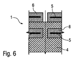
図5〜図7にかかる実施形態もまた、上述の実施形態に部分的に一致する。重複を避けるため、上述の説明を参照し、対応する要素には同一の符号を用いる。 The embodiment according to FIGS. 5 to 7 also partially corresponds to the embodiment described above. In order to avoid duplication, reference is made to the above description and the same reference numerals are used for corresponding elements.
これらの実施形態の特徴は、まず第1に、プラズマ発生器3が容積性誘電体バリア放電(「容積DBD」)によりプラズマを発生させることにあり、図2〜図4にかかる実施形態におけるプラズマ発生は、表面性誘電体バリア放電(「表面DBD」)によって行われる。
The feature of these embodiments is that, first of all, the
よって、図5〜図7にかかる実施形態において、触媒と吸着体との結合体4は、プラズマ発生器3の前側の上流側およびプラズマ発生器3の背後の下流側の両方、ならびにプラズマ発生器3の領域に位置する。
Therefore, in the embodiment according to FIGS. 5 to 7, the combined
図8〜図10に、図2〜図4にかかる実施形態のさらに別の変形例を示す。重複を避けるため、上述の説明を参照し、対応する要素には同一の符号を用いる。 8 to 10 show still another modification of the embodiment according to FIGS. In order to avoid duplication, reference is made to the above description and the same reference numerals are used for corresponding elements.
これらの実施形態の特徴は、プラズマ発生器3の前側の上流側、すなわち吸着体と触媒との結合体4の前側の上流側でもある位置に、浄化作用を向上させるために、UV光源(不図示)によって照射されさらに浄化対象の空気を処理する光触媒7が配置されることにある。
The feature of these embodiments is that a UV light source (non-light source) is used in order to improve the purification action at the upstream side of the front side of the
図11〜図13に、図5〜図7にかかる実施形態の変形例を示す。重複を避けるため、上述の説明を参照し、対応する要素には同一の符号を用いる。 FIGS. 11 to 13 show modifications of the embodiment according to FIGS. In order to avoid duplication, reference is made to the above description and the same reference numerals are used for corresponding elements.
これらの実施形態の特徴は、光触媒7の浄化作用を向上させるために、UV光源によって照射される触媒7がさらに設けられることにある。
A feature of these embodiments is that a
また、図14に、本発明にかかる空気浄化装置1の単純化した模式図を示す。重複を避けるため、上述の説明を参照し、対応する要素には同一の符号を用いる。
FIG. 14 shows a simplified schematic diagram of the
ここで、触媒と吸着体との結合体4は、全体的にプラズマ発生器3の背後の下流側に配置される。
Here, the combined
図15にかかる実施形態は、図14にかかる実施形態に部分的に一致する。重複を避けるため、上述の説明を参照し、対応する要素には同一の符号を用いる。 The embodiment according to FIG. 15 partially corresponds to the embodiment according to FIG. In order to avoid duplication, reference is made to the above description and the same reference numerals are used for corresponding elements.
本実施形態の特徴は、プラズマ発生器3の領域に触媒がさらに配置されることにある。
The feature of this embodiment is that a catalyst is further arranged in the region of the
最後に、図16にかかる実施形態は、上述の実施形態に部分的に一致する。重複を避けるため、上述の説明を参照し、対応する要素には同一の符号を用いる。 Finally, the embodiment according to FIG. 16 partially corresponds to the embodiment described above. In order to avoid duplication, reference is made to the above description and the same reference numerals are used for corresponding elements.
本実施形態の特徴は、プラズマ発生器3の前側の上流側である位置に、UV光源8によって照射される光触媒7が設けられることにあり、この光触媒7はさらに浄化作用を向上させる。
The feature of this embodiment is that a
本発明は、上記の好適な実施形態に限定されるものではない。むしろ、本発明の概念を利用し、よって保護の範囲に含まれる、複数の変更例や変形例が可能である。また、本発明は、従属請求項の主題と特徴の保護を、参照対象の請求項の特徴とは別に、主張するものである。よって、従属請求項は、部分的に、単独で保護に値する本発明の様態を開示するものである。 The present invention is not limited to the preferred embodiments described above. Rather, multiple modifications and variations are possible that utilize the concepts of the present invention and are thus within the scope of protection. The present invention also claims protection of the subject matter and characteristics of the dependent claims separately from the characteristics of the referenced claims. Thus, the dependent claims partially disclose aspects of the invention that are worthy of protection alone.
1:空気浄化装置
2:流路
3:プラズマ発生器
4:吸着と触媒との結合体
5:電極
6:誘電体
7:光触媒
8:UV光源
1: Air purifier 2: Channel 3: Plasma generator 4: Combined adsorption and catalyst 5: Electrode 6: Dielectric 7: Photocatalyst 8: UV light source
Claims (17)
a)浄化対象の空気をプラズマで処理するプラズマ発生器(3)と、
b)空気から不純物を吸収し反応面を形成する吸着体(4)と、
c)空気中の不純物を触媒変成する触媒(4)とを備え、
d)前記吸着体(4)と前記触媒(4)とは、少なくとも部分的に前記プラズマ発生器(3)の背後の下流側に配置され、
e)円周状の壁部を含む筒状の流路(2)と、
f)前記筒状の流路(2)内を延びる浄化対象の空気の流通経路と、
を備え、
g)浄化対象の空気の流通経路は、初めは筒状の流路(2)内を基本的に軸方向に、次に前記筒状の流路(2)の前記円周状の壁部を基本的に放射状に通って延び、
h)前記プラズマ発生器(3)の電極(5)、前記吸着体(4)、および、前記触媒(4)のうちの少なくとも1つは、全体的に前記筒状の流路(2)の前記円周状の壁部内に配置されること、
を特徴とする空気浄化装置。 An air purification device (1) for purifying air in a building ,
a) a plasma generator (3) for treating the air to be purified with plasma ;
b) an adsorbent (4) that absorbs impurities from the air to form a reaction surface;
c) a catalyst (4) for catalytically modifying impurities in the air,
d) the adsorbent (4) and the catalyst (4) are at least partially disposed downstream of the plasma generator (3) ;
e) a cylindrical channel (2) including a circumferential wall;
f) a flow path of air to be purified extending through the cylindrical flow path (2);
With
g) The flow path of the air to be purified is basically axial in the cylindrical channel (2) and then the circumferential wall of the cylindrical channel (2). Basically extending radially,
h) At least one of the electrode (5), the adsorbent (4), and the catalyst (4) of the plasma generator (3) is entirely formed of the cylindrical flow path (2). Being disposed within the circumferential wall,
An air purifier characterized by.
a)前記プラズマを発生させるプラズマ発生器(3)は、複数の電極(5)を有し、前記電極(5)の間の容積に容積性誘電体バリア放電を発生させ、
b)前記吸着体(4)と前記触媒(4)とは、少なくとも部分的に前記プラズマ発生器(3)の前記電極(5)の間に配置され、部分的に前記プラズマ発生器(3)の背後の下流側に配置されることを特徴とする空気浄化装置。 An air purification device (1) according to claim 1,
a) The plasma generator (3) for generating the plasma has a plurality of electrodes (5), and generates a volumetric dielectric barrier discharge in the volume between the electrodes (5),
b) The adsorbent (4) and the catalyst (4) are at least partly disposed between the electrodes (5) of the plasma generator (3) and partly the plasma generator (3). An air purifier arranged on the downstream side behind the hood.
a)前記プラズマを発生させるプラズマ発生器(3)は、複数の電極(5)を有し、表面に表面性誘電体バリア放電を発生させ、
b)前記吸着体(4)と前記触媒(4)とは、全体的に前記プラズマ発生器(3)の背後の下流側に配置されることを特徴とする空気浄化装置。 An air purification device (1) according to claim 1,
a) The plasma generator (3) for generating the plasma has a plurality of electrodes (5), generates a surface dielectric barrier discharge on the surface,
b) The air purification device, wherein the adsorbent (4) and the catalyst (4) are disposed on the downstream side behind the plasma generator (3) as a whole.
a)前記プラズマを発生させるプラズマ発生器(3)は、複数の電極(5)を有し、
b)前記プラズマ発生器(3)の前記電極(5)は、少なくとも部分的に空気透過性を有し、
c)浄化対象の空気は、前記空気浄化装置(1)内の流通経路に沿って流れ、
d)浄化対象の空気の流通経路は、前記プラズマ発生器(3)の前記空気透過性を有する電極(5)内を通って延びることを特徴とする空気浄化装置。 An air purification device (1) according to any one of claims 1 to 3, wherein
a) The plasma generator (3) for generating the plasma has a plurality of electrodes (5),
b) the electrode (5) of the plasma generator (3) is at least partially air permeable;
c) The air to be purified flows along the flow path in the air purification device (1),
d) The air purification device, wherein the flow path of air to be purified extends through the air permeable electrode (5) of the plasma generator (3).
前記吸着体(4)と前記触媒(4)とは、空気が前記吸着体(4)と前記触媒(4)とを同時に流れるように、混合されていることを特徴とする空気浄化装置。 An air purification device (1) according to any one of claims 1 to 4 , comprising:
The adsorbent (4) and the catalyst (4) are mixed so that air flows through the adsorbent (4) and the catalyst (4) simultaneously.
前記吸着体(4)と前記触媒(4)とは、流れ方向に順番に配置されていることを特徴とする空気浄化装置。 The adsorbent (4) and the catalyst (4) are arranged in order in the flow direction.
複数の吸着体(4)が設けられていることを特徴とする空気浄化装置。 An air purification device (1) according to any one of claims 1 to 6 , comprising:
Air purification device, wherein a plurality of adsorbent (4) is provided.
複数の触媒(4)が設けられていることを特徴とする空気浄化装置。 An air purifier characterized by comprising a plurality of catalysts (4).
前記プラズマ発生器(3)を電気的に駆動する駆動装置を備え、
前記駆動装置は、前記プラズマ発生器(3)のオンオフを交互に切り替え、
スイッチオン状態で発生したプラズマは、前記吸着体および前記触媒を再活性化させ、および、浄化することを特徴とする空気浄化装置。 An air purification device (1) according to any one of claims 1 to 8, comprising:
A driving device for electrically driving the plasma generator (3);
The driving device alternately switches on and off the plasma generator (3),
An air purification apparatus characterized in that plasma generated in a switch-on state reactivates and purifies the adsorbent and the catalyst.
浄化対象の空気を照射する紫外線を発生させるUV光源(8)を備えることを特徴とする空気浄化装置。 An air purification device (1) according to any one of claims 1 to 9, wherein
An air purification apparatus comprising a UV light source (8) that generates ultraviolet rays that irradiate air to be purified.
空気を処理する光触媒(7)を備え、
前記光触媒(7)は、前記UV光源(8)の紫外線を浴びて浄化対象の空気に作用することを特徴とする空気浄化装置。 An air purification device (1) according to claim 10,
A photocatalyst (7) for treating air;
The air purification apparatus, wherein the photocatalyst (7) acts on the air to be purified by receiving the ultraviolet light from the UV light source (8).
前記光触媒(7)は、二酸化チタン、または、プラチナと二酸化チタンとの混合物を含むことを特徴とする空気浄化装置。 An air purification device (1) according to claim 11,
The photocatalyst (7), titanium dioxide, or air purification device which comprises a mixture of platinum and titanium dioxide.
前記触媒(4)は、二酸化マンガン、酸化銅(II)、および、酸化アルミニウムのうちの少なくとも1つを含むことを特徴とする空気浄化装置。 The air purification apparatus, wherein the catalyst (4) includes at least one of manganese dioxide, copper (II) oxide, and aluminum oxide.
前記吸着体(4)は、活性炭、および、ゼオライトのうちの少なくとも1つを含むことを特徴とする空気浄化装置。 The adsorbent (4) includes at least one of activated carbon and zeolite.
前記空気浄化装置(1)は、外部の空気を吸い込み、吸い込んだ外部の空気を浄化し、浄化した外部の空気を建造物の室内に供給することを特徴とする空気浄化装置。 The air purification device (1) according to any one of claims 1 to 14 ,
The air purifying device (1) sucks external air, purifies the sucked external air, and supplies the purified external air into a building room.
前記空気浄化装置(1)は、建造物の室内から室内の空気を引き出し、引き出した室内の空気を浄化し、浄化した室内の空気を建造物の室内に再供給することを特徴とする空気浄化装置。 The air purification device (1) extracts indoor air from a room of a building, purifies the indoor air drawn out, and re-supplys the purified indoor air to the room of the building. apparatus.
前記空気浄化装置(1)は、建造物の室内から室内の空気を引き出し、吸い込んだ室内の空気を浄化し、浄化した室内の空気を外部に供給することを特徴とする空気浄化装置。 The air purification apparatus (1) is characterized in that indoor air is drawn out from a room of a building, the air in the room is purified, and the purified room air is supplied to the outside.
Applications Claiming Priority (3)
| Application Number | Priority Date | Filing Date | Title |
|---|---|---|---|
| DE102012010342.5 | 2012-05-25 | ||
| DE102012010342A DE102012010342A1 (en) | 2012-05-25 | 2012-05-25 | Air cleaning device |
| PCT/EP2013/001030 WO2013174467A2 (en) | 2012-05-25 | 2013-04-08 | Air cleaning device |
Publications (2)
| Publication Number | Publication Date |
|---|---|
| JP2015526107A JP2015526107A (en) | 2015-09-10 |
| JP5918907B2 true JP5918907B2 (en) | 2016-05-18 |
Family
ID=48050661
Family Applications (1)
| Application Number | Title | Priority Date | Filing Date |
|---|---|---|---|
| JP2015513033A Active JP5918907B2 (en) | 2012-05-25 | 2013-04-08 | Air purification device |
Country Status (7)
| Country | Link |
|---|---|
| EP (1) | EP2854877B1 (en) |
| JP (1) | JP5918907B2 (en) |
| KR (1) | KR101674494B1 (en) |
| CN (1) | CN104334199B (en) |
| DE (1) | DE102012010342A1 (en) |
| SI (1) | SI2854877T1 (en) |
| WO (1) | WO2013174467A2 (en) |
Cited By (1)
| Publication number | Priority date | Publication date | Assignee | Title |
|---|---|---|---|---|
| IT201800009790A1 (en) * | 2018-10-25 | 2020-04-25 | Poloplasma Srl | AIR PURIFICATION SYSTEM IN A VENTILATION SYSTEM WITH CONTROLLED OUTLET |
Families Citing this family (8)
| Publication number | Priority date | Publication date | Assignee | Title |
|---|---|---|---|---|
| DE202013001963U1 (en) * | 2013-02-27 | 2013-05-02 | Al-Ko Kober Ag | Room air cleaner |
| CN105903321B (en) * | 2016-06-13 | 2018-06-08 | 山东大学 | A kind of low energy consumption low temperature plasma gas reaction unit |
| CN106268301B (en) * | 2016-08-29 | 2023-07-04 | 重庆悦森生态科技有限公司 | Air purifying and filtering system with super-strong adsorption force |
| JP6645385B2 (en) * | 2016-08-30 | 2020-02-14 | 株式会社デンソー | Gas reformer |
| CN110962549A (en) * | 2019-12-31 | 2020-04-07 | 河海大学常州校区 | Vehicle-mounted air purification and anion generator |
| CN111773900B (en) * | 2020-07-07 | 2021-06-25 | 浙江工贸职业技术学院 | On-line detection and purification device applied to volatile organic compounds in industrial waste gas |
| DE102020120582A1 (en) | 2020-08-04 | 2022-02-10 | Cinogy Gmbh | Gas cleaning device and method for cleaning a gas |
| KR102372430B1 (en) | 2021-04-29 | 2022-03-10 | 주식회사 어소시에이츠 엘작 | Guide sign structure system |
Family Cites Families (15)
| Publication number | Priority date | Publication date | Assignee | Title |
|---|---|---|---|---|
| GB9904640D0 (en) * | 1999-03-02 | 1999-04-21 | Aea Technology Plc | Plasma-assisted processing of gaseous media |
| CZ20023355A3 (en) * | 2000-04-11 | 2003-06-18 | Accentus Plc | Catalytic material, process of its preparation, method, and reactor for processing exhaust gases |
| JP3649241B1 (en) * | 2003-03-04 | 2005-05-18 | ダイキン工業株式会社 | Air cleaning member and air conditioner |
| JP2004344719A (en) * | 2003-05-20 | 2004-12-09 | Toyota Motor Corp | Exhaust emission control device |
| CN100505449C (en) * | 2003-08-29 | 2009-06-24 | 大金工业株式会社 | Discharging device and air cleaner |
| US7767169B2 (en) * | 2003-12-11 | 2010-08-03 | Sharper Image Acquisition Llc | Electro-kinetic air transporter-conditioner system and method to oxidize volatile organic compounds |
| JP2005300111A (en) * | 2004-04-15 | 2005-10-27 | Daikin Ind Ltd | Air cleaning unit, air conditioner and air conditioning system |
| JP2005342142A (en) * | 2004-06-02 | 2005-12-15 | Daikin Ind Ltd | Air purifier and air conditioner using it |
| US7740810B2 (en) * | 2004-12-14 | 2010-06-22 | Carrier Corporation | Photocatalyst protection |
| JP2006308225A (en) * | 2005-04-28 | 2006-11-09 | Kurita Water Ind Ltd | Gas collecting device and deodorizing device using the same |
| WO2007070704A2 (en) * | 2005-12-17 | 2007-06-21 | Airinspace B.V. | Air purification devices |
| EP2012904A2 (en) * | 2006-02-17 | 2009-01-14 | Plasma Clean Limited | Gas treatment using a plurality of plasma generating reactor units |
| DE102006023069B4 (en) | 2006-05-17 | 2008-09-18 | Johannes Dipl.-Ing. Schedler | Plasma reactor and process for the purification of airborne pollutants and germs, as well as bulk material for filling the plasma reactor |
| KR101206360B1 (en) * | 2010-05-24 | 2012-11-29 | 국방과학연구소 | Apparatus and method for the chemical and biological warfare agent decontamination |
| DE102012109253A1 (en) * | 2012-09-28 | 2014-04-03 | Manfred H. Langner | Air filter module |
-
2012
- 2012-05-25 DE DE102012010342A patent/DE102012010342A1/en active Pending
-
2013
- 2013-04-08 EP EP13714860.7A patent/EP2854877B1/en active Active
- 2013-04-08 SI SI201332069T patent/SI2854877T1/en unknown
- 2013-04-08 KR KR1020147032594A patent/KR101674494B1/en active IP Right Grant
- 2013-04-08 WO PCT/EP2013/001030 patent/WO2013174467A2/en active Application Filing
- 2013-04-08 CN CN201380027525.8A patent/CN104334199B/en active Active
- 2013-04-08 JP JP2015513033A patent/JP5918907B2/en active Active
Cited By (1)
| Publication number | Priority date | Publication date | Assignee | Title |
|---|---|---|---|---|
| IT201800009790A1 (en) * | 2018-10-25 | 2020-04-25 | Poloplasma Srl | AIR PURIFICATION SYSTEM IN A VENTILATION SYSTEM WITH CONTROLLED OUTLET |
Also Published As
| Publication number | Publication date |
|---|---|
| DE102012010342A1 (en) | 2013-11-28 |
| WO2013174467A3 (en) | 2014-04-17 |
| CN104334199B (en) | 2017-04-12 |
| CN104334199A (en) | 2015-02-04 |
| KR20150015468A (en) | 2015-02-10 |
| EP2854877B1 (en) | 2023-09-20 |
| SI2854877T1 (en) | 2024-03-29 |
| KR101674494B1 (en) | 2016-11-09 |
| WO2013174467A8 (en) | 2014-02-27 |
| EP2854877A2 (en) | 2015-04-08 |
| WO2013174467A2 (en) | 2013-11-28 |
| JP2015526107A (en) | 2015-09-10 |
Similar Documents
| Publication | Publication Date | Title |
|---|---|---|
| JP5918907B2 (en) | Air purification device | |
| KR101386404B1 (en) | Air sterilization purifier with oval tubular photocatalysts module and ion cluster generating module | |
| JP4195905B2 (en) | Air decontamination equipment and method | |
| JP5598770B2 (en) | Improved air decontamination equipment | |
| JP5706975B2 (en) | Humidifier using photocatalyst with air cleaning function | |
| JP5837109B2 (en) | Gas decomposition filter unit and air purifier | |
| JP2008516652A (en) | Method and apparatus for sterilizing ambient air | |
| KR101046214B1 (en) | Apparatus and method for sterilizing and deodorizing | |
| CN201260930Y (en) | High-efficient air purification device | |
| JP2008289801A (en) | Gas purification device | |
| JP4095620B2 (en) | Gas processing equipment | |
| KR102278240B1 (en) | Photoluminescent photocatalytic air purifier system | |
| KR20150078158A (en) | Air cleaning device | |
| CN206184229U (en) | Low temperature plasma ultraviolet photolysis exhaust gas cleaner | |
| KR101708220B1 (en) | The desk with air purification function | |
| JP2009513315A (en) | Equipment for purifying waste air containing harmful substances | |
| CN208512274U (en) | A kind of off-gas cleaning equipment | |
| JP2018531173A (en) | Air conditioner | |
| JP2018531173A6 (en) | Air conditioner | |
| CN211724145U (en) | Air sterilizer with plasma and high-efficiency composite filtering technology | |
| KR101559324B1 (en) | Contactless deodorizing apparatus with photo-catalysts mesh-matrix | |
| JP2003310723A (en) | Air cleaner and catalyst | |
| JP2004044882A (en) | Air cleaner | |
| CN113944975A (en) | Sterilizing machine | |
| KR200396959Y1 (en) | Device for Eliminating Noxious Gas |
Legal Events
| Date | Code | Title | Description |
|---|---|---|---|
| A131 | Notification of reasons for refusal |
Free format text: JAPANESE INTERMEDIATE CODE: A131 Effective date: 20151201 |
|
| A521 | Request for written amendment filed |
Free format text: JAPANESE INTERMEDIATE CODE: A523 Effective date: 20160217 |
|
| TRDD | Decision of grant or rejection written | ||
| A01 | Written decision to grant a patent or to grant a registration (utility model) |
Free format text: JAPANESE INTERMEDIATE CODE: A01 Effective date: 20160405 |
|
| A61 | First payment of annual fees (during grant procedure) |
Free format text: JAPANESE INTERMEDIATE CODE: A61 Effective date: 20160408 |
|
| R150 | Certificate of patent or registration of utility model |
Ref document number: 5918907 Country of ref document: JP Free format text: JAPANESE INTERMEDIATE CODE: R150 |
|
| R250 | Receipt of annual fees |
Free format text: JAPANESE INTERMEDIATE CODE: R250 |
|
| R250 | Receipt of annual fees |
Free format text: JAPANESE INTERMEDIATE CODE: R250 |
|
| R250 | Receipt of annual fees |
Free format text: JAPANESE INTERMEDIATE CODE: R250 |
|
| R250 | Receipt of annual fees |
Free format text: JAPANESE INTERMEDIATE CODE: R250 |
|
| R250 | Receipt of annual fees |
Free format text: JAPANESE INTERMEDIATE CODE: R250 |
|
| R250 | Receipt of annual fees |
Free format text: JAPANESE INTERMEDIATE CODE: R250 |