JP5916706B2 - Crimping press - Google Patents
Crimping press Download PDFInfo
- Publication number
- JP5916706B2 JP5916706B2 JP2013504380A JP2013504380A JP5916706B2 JP 5916706 B2 JP5916706 B2 JP 5916706B2 JP 2013504380 A JP2013504380 A JP 2013504380A JP 2013504380 A JP2013504380 A JP 2013504380A JP 5916706 B2 JP5916706 B2 JP 5916706B2
- Authority
- JP
- Japan
- Prior art keywords
- crimping
- force
- press
- tool
- spring
- Prior art date
- Legal status (The legal status is an assumption and is not a legal conclusion. Google has not performed a legal analysis and makes no representation as to the accuracy of the status listed.)
- Active
Links
- 238000002788 crimping Methods 0.000 title claims description 181
- 238000000034 method Methods 0.000 claims description 56
- 230000008569 process Effects 0.000 claims description 55
- 238000001514 detection method Methods 0.000 claims description 5
- 229920001971 elastomer Polymers 0.000 claims description 5
- 239000000806 elastomer Substances 0.000 claims description 5
- 238000003825 pressing Methods 0.000 claims description 4
- 230000003313 weakening effect Effects 0.000 claims description 4
- 239000002131 composite material Substances 0.000 claims description 3
- 238000012790 confirmation Methods 0.000 claims description 3
- 239000000835 fiber Substances 0.000 claims description 3
- 230000000694 effects Effects 0.000 description 11
- 230000005856 abnormality Effects 0.000 description 5
- 230000007246 mechanism Effects 0.000 description 5
- 230000002829 reductive effect Effects 0.000 description 4
- 239000007788 liquid Substances 0.000 description 3
- 235000017166 Bambusa arundinacea Nutrition 0.000 description 2
- 235000017491 Bambusa tulda Nutrition 0.000 description 2
- 241001330002 Bambuseae Species 0.000 description 2
- 235000015334 Phyllostachys viridis Nutrition 0.000 description 2
- 230000009471 action Effects 0.000 description 2
- 230000002411 adverse Effects 0.000 description 2
- 239000011425 bamboo Substances 0.000 description 2
- 230000009286 beneficial effect Effects 0.000 description 2
- 230000008859 change Effects 0.000 description 2
- 210000000078 claw Anatomy 0.000 description 2
- 230000007423 decrease Effects 0.000 description 2
- 230000001747 exhibiting effect Effects 0.000 description 2
- 230000006872 improvement Effects 0.000 description 2
- 238000005461 lubrication Methods 0.000 description 2
- 238000005259 measurement Methods 0.000 description 2
- 230000002159 abnormal effect Effects 0.000 description 1
- 230000032683 aging Effects 0.000 description 1
- 244000309464 bull Species 0.000 description 1
- 230000000739 chaotic effect Effects 0.000 description 1
- 238000004891 communication Methods 0.000 description 1
- 238000011109 contamination Methods 0.000 description 1
- 238000013016 damping Methods 0.000 description 1
- 230000003247 decreasing effect Effects 0.000 description 1
- 230000001419 dependent effect Effects 0.000 description 1
- 238000009795 derivation Methods 0.000 description 1
- 230000003670 easy-to-clean Effects 0.000 description 1
- 238000004870 electrical engineering Methods 0.000 description 1
- 239000003925 fat Substances 0.000 description 1
- 239000012530 fluid Substances 0.000 description 1
- 239000004519 grease Substances 0.000 description 1
- 238000005304 joining Methods 0.000 description 1
- 230000001050 lubricating effect Effects 0.000 description 1
- 238000012423 maintenance Methods 0.000 description 1
- 238000004519 manufacturing process Methods 0.000 description 1
- 230000036961 partial effect Effects 0.000 description 1
- 229920001296 polysiloxane Polymers 0.000 description 1
- 238000001303 quality assessment method Methods 0.000 description 1
- 230000002441 reversible effect Effects 0.000 description 1
- 238000005476 soldering Methods 0.000 description 1
- 239000000126 substance Substances 0.000 description 1
- 230000001629 suppression Effects 0.000 description 1
- 239000003981 vehicle Substances 0.000 description 1
- 238000003466 welding Methods 0.000 description 1
Images


Classifications
-
- H—ELECTRICITY
- H01—ELECTRIC ELEMENTS
- H01R—ELECTRICALLY-CONDUCTIVE CONNECTIONS; STRUCTURAL ASSOCIATIONS OF A PLURALITY OF MUTUALLY-INSULATED ELECTRICAL CONNECTING ELEMENTS; COUPLING DEVICES; CURRENT COLLECTORS
- H01R43/00—Apparatus or processes specially adapted for manufacturing, assembling, maintaining, or repairing of line connectors or current collectors or for joining electric conductors
- H01R43/04—Apparatus or processes specially adapted for manufacturing, assembling, maintaining, or repairing of line connectors or current collectors or for joining electric conductors for forming connections by deformation, e.g. crimping tool
- H01R43/048—Crimping apparatus or processes
- H01R43/0482—Crimping apparatus or processes combined with contact member manufacturing mechanism
-
- H—ELECTRICITY
- H01—ELECTRIC ELEMENTS
- H01R—ELECTRICALLY-CONDUCTIVE CONNECTIONS; STRUCTURAL ASSOCIATIONS OF A PLURALITY OF MUTUALLY-INSULATED ELECTRICAL CONNECTING ELEMENTS; COUPLING DEVICES; CURRENT COLLECTORS
- H01R43/00—Apparatus or processes specially adapted for manufacturing, assembling, maintaining, or repairing of line connectors or current collectors or for joining electric conductors
- H01R43/04—Apparatus or processes specially adapted for manufacturing, assembling, maintaining, or repairing of line connectors or current collectors or for joining electric conductors for forming connections by deformation, e.g. crimping tool
- H01R43/048—Crimping apparatus or processes
- H01R43/0484—Crimping apparatus or processes for eyelet contact members
-
- H—ELECTRICITY
- H01—ELECTRIC ELEMENTS
- H01R—ELECTRICALLY-CONDUCTIVE CONNECTIONS; STRUCTURAL ASSOCIATIONS OF A PLURALITY OF MUTUALLY-INSULATED ELECTRICAL CONNECTING ELEMENTS; COUPLING DEVICES; CURRENT COLLECTORS
- H01R43/00—Apparatus or processes specially adapted for manufacturing, assembling, maintaining, or repairing of line connectors or current collectors or for joining electric conductors
- H01R43/04—Apparatus or processes specially adapted for manufacturing, assembling, maintaining, or repairing of line connectors or current collectors or for joining electric conductors for forming connections by deformation, e.g. crimping tool
- H01R43/048—Crimping apparatus or processes
- H01R43/0486—Crimping apparatus or processes with force measuring means
-
- H—ELECTRICITY
- H01—ELECTRIC ELEMENTS
- H01R—ELECTRICALLY-CONDUCTIVE CONNECTIONS; STRUCTURAL ASSOCIATIONS OF A PLURALITY OF MUTUALLY-INSULATED ELECTRICAL CONNECTING ELEMENTS; COUPLING DEVICES; CURRENT COLLECTORS
- H01R43/00—Apparatus or processes specially adapted for manufacturing, assembling, maintaining, or repairing of line connectors or current collectors or for joining electric conductors
- H01R43/04—Apparatus or processes specially adapted for manufacturing, assembling, maintaining, or repairing of line connectors or current collectors or for joining electric conductors for forming connections by deformation, e.g. crimping tool
- H01R43/048—Crimping apparatus or processes
- H01R43/0488—Crimping apparatus or processes with crimp height adjusting means
-
- Y—GENERAL TAGGING OF NEW TECHNOLOGICAL DEVELOPMENTS; GENERAL TAGGING OF CROSS-SECTIONAL TECHNOLOGIES SPANNING OVER SEVERAL SECTIONS OF THE IPC; TECHNICAL SUBJECTS COVERED BY FORMER USPC CROSS-REFERENCE ART COLLECTIONS [XRACs] AND DIGESTS
- Y10—TECHNICAL SUBJECTS COVERED BY FORMER USPC
- Y10T—TECHNICAL SUBJECTS COVERED BY FORMER US CLASSIFICATION
- Y10T29/00—Metal working
- Y10T29/53—Means to assemble or disassemble
- Y10T29/5313—Means to assemble electrical device
- Y10T29/532—Conductor
- Y10T29/53209—Terminal or connector
- Y10T29/53213—Assembled to wire-type conductor
- Y10T29/53235—Means to fasten by deformation
Description
本発明は、第1圧着ツールと、第1圧着ツールに対して可動な第2圧着ツールと、圧着プロセス実行中に第1・第2圧着ツール間に圧着力を作用させるドライブと、を備える圧着プレスに関する。 The present invention includes a first crimping tool, a second crimping tool movable with respect to the first crimping tool, and a drive that applies a crimping force between the first and second crimping tools during the crimping process. Regarding the press.
圧着はフランジングの一種であり、ワイヤやケーブルを電極、例えばプラグ状のそれに塑性変形で接合する結合プロセスと認められている。もたらされる導体・電極間接合が恒久的で電気的・機械的信頼性が高いため、半田付け、熔接等の既存接合手法の代わりに使用することができる。そのため、電気工学上の利用分野が非常に広く、高周波電子回路、通信、車載電機等に亘っている。 Crimping is a type of flanging and is recognized as a joining process in which wires and cables are joined to electrodes, such as plugs, by plastic deformation. Since the resulting conductor-electrode joint is permanent and has high electrical and mechanical reliability, it can be used in place of existing joint techniques such as soldering and welding. Therefore, the field of application in electrical engineering is very wide and covers high frequency electronic circuits, communication, on-vehicle electric machines and the like.
圧着に使用されるプロセスは、そのプロファイルを圧着対象部品及び電極の断面にしっかりと一致させた上で圧力を加え、それらの部品及び電極を精度よく所定形状に変形させるプロセスである。このプロセスには、通常、特殊な圧着ペンチか圧着プレスが使用される。圧着ペンチが一般に単純な仕組みであるのに対し、圧着プレスの仕組みは若干複雑である。仕上がり前のワークピース、例えばその一部分が予め剥き身にされているワイヤ乃至ケーブルを圧着プレスに通し、その圧着プレス内に装填されている電極の圧着爪でそのワイヤ乃至ケーブルを挟み込み、そしてその圧着プレスに備わる圧着ツールによって電極もろともワイヤ乃至ケーブルを加圧する仕組みである。圧着プロセスで必要とされる圧力は、圧着ツールをパンチで加圧することで得られる。 The process used for crimping is a process in which the profile is firmly matched with the cross-sections of the parts to be crimped and the electrodes, and pressure is applied to deform the parts and electrodes into a predetermined shape with high accuracy. This process usually uses special crimping pliers or crimping presses. While a crimping pliers is generally a simple mechanism, the mechanism of a crimping press is somewhat complicated. A finished workpiece, for example, a wire or cable partially stripped in advance, is passed through a crimping press, the wire or cable is sandwiched between crimping claws of an electrode loaded in the crimping press, and the crimping press This is a mechanism for pressurizing wires and cables together with the electrodes using a crimping tool. The pressure required in the crimping process can be obtained by pressing the crimping tool with a punch.
こうしたプロセスには、例えば、特許文献1記載の如く、圧着ツール及び結合解除ツールを備えており、圧着ツールに対するバネ付勢で圧着プロセス実行中にケーブル及び電極の位置を保持する圧着プレスを、使用することが可能である。 In such a process, for example, as described in Patent Document 1, a crimping tool and a decoupling tool are provided, and a crimping press that holds the position of the cable and the electrode during the crimping process by using a spring bias against the crimping tool is used. Is possible.
同様に、特許文献2記載の如く、ツール本体内にありバネ力によって相互離隔されている2個の圧着顎をラムの働きで一体に初期駆動し、それによって圧着顎間に捉えたワイヤをラムによる圧着顎搬送部材の下方駆動で圧着爪内に送る構成の圧着プレスも、使用することが可能である。
Similarly, as described in
いずれにせよ、生じる圧着接合部を良質にするため、また良質な圧着接合部を多数回に亘り連続的に得るためには、圧着プロセス実行中に、力対経路曲線や力対時間曲線をかなり頻繁にチェックする必要があろう。例えば、圧着プレス同士の間に作用する力をツール間距離に関連付けつつ計測し、幾種類かの標的パラメタとの関連で解析する。それにより求まった曲線が狙いとする曲線から大きく外れていたら、問題が生じている圧着接合部での結合を解除する、或いは問題のない圧着接合部が形成されるよう圧着プレスの諸パラメタを再調整する、といった具合である。 In any case, in order to improve the quality of the resulting crimped joint and to obtain a good quality crimped joint continuously many times, the force vs. path and force vs. time curves can be significantly increased during the crimping process. You will need to check frequently. For example, the force acting between the crimping presses is measured in relation to the distance between the tools, and analyzed in relation to several types of target parameters. If the calculated curve deviates significantly from the target curve, the parameters of the crimping press are reset so that the bond at the crimp joint where the problem has occurred is released, or a crimp joint with no problem is formed. For example, adjustment.
在来の圧着プレスには、そのドライブが複数個の可動部材及びそれらを相互連結するベアリングで構成される、という短所がある。例えば偏心型の圧着プレスでは、ドライブシャフトベアリングを伴うドライブシャフト上のカムが連結ロッド内にはめ込まれる。その連結ロッドは、キャリッジガイドによって側部支持されているプレスキャリッジに、連結ロッドベアリングを介し作用する。 Conventional crimping presses have the disadvantage that their drives are composed of a plurality of movable members and bearings that interconnect them. For example, in an eccentric type crimping press, a cam on a drive shaft with a drive shaft bearing is fitted in a connecting rod. The connecting rod acts via a connecting rod bearing on a press carriage that is laterally supported by a carriage guide.
このように部品間運動がある構成ではどのベアリングにも遊びが生じる。この遊びは、非常に高感度な計測装置を用いその圧着プロセスにおける典型的な力対経路乃至時間曲線を求める処理に悪影響を及ぼす。それは、圧着プロセス実行中に、ベアリングの表面同士がかなりの力で押し合っているからである。しかも、その加圧は概ね非制御的な様相で生じ、ときとしてカオス的な様相になることもある。そうなるのは、個々のベアリングに備わるベアリング面同士の接触タイミングが、ベアリングの種類、作用する力、諸ベアリングの潤滑特性、使用しているツールの種類、処理対象となっているワークピースの種類等によって異なるからであり、力対経路乃至時間曲線には、その影響が平坦領域(経路乃至時刻が変化しても力が一定な領域)、極小領域乃至不連続領域となって現れる。しかも、圧着プレスの作動時間が延びるにつれ条件が変化すること、即ち諸ベアリングにおける潤滑状態変化、汚濁、摩耗等が進むことも事態を複雑化させている。 In such a configuration with movement between parts, play occurs in any bearing. This play adversely affects the process of using a highly sensitive measuring device to determine the typical force versus path or time curve in the crimping process. This is because the bearing surfaces are pressed against each other with considerable force during the crimping process. Moreover, the pressurization occurs in a generally uncontrolled manner and sometimes in a chaotic manner. The reason for this is that the contact timing between the bearing surfaces of each bearing depends on the type of bearing, the force applied, the lubrication characteristics of the bearings, the type of tool used, and the type of workpiece being processed. For example, the force vs. path or time curve shows the influence as a flat area (area where the force is constant even if the path or time changes), a minimum area or a discontinuous area. In addition, the conditions change as the operation time of the crimping press increases, that is, the lubrication state changes, contamination, wear, and the like in the bearings also complicate the situation.
圧着プレスにて生じるこうした予測不能な影響が力対経路乃至時間曲線に及ぶため、その曲線を用いたとしても、生じる圧着接合部の質に関し情報を少ししか得られないし、得られた情報が実際の圧着状態を反映していないこともままある。場合によっては、求まった力対経路乃至時間曲線の構成諸部分が圧着プレス由来かそれともワークピース由来かが不明瞭になることもある。これが非常に不都合であることは容易にご理解頂けよう。 Because these unpredictable effects that occur in a crimping press extend to the force vs. path or time curve, using that curve provides little information about the quality of the resulting crimp joint, and the information obtained is actually In some cases, it does not reflect the state of crimping. In some cases, it may be unclear whether the components of the determined force versus path or time curve are from a crimping press or from a workpiece. You can easily understand that this is very inconvenient.
従来、これへの対策としては、できるだけ遊びが少ないベアリングを圧着プレス向けに生産する策や、個別主要部品の精密な製造を通じベアリングを然るべく調整する策が採られてきた。例えば、タイトナブルバレルローラベアリング、コーンベアリング等を使用する策である。いずれの策を採るにしても、技術的に複雑な策であることから時間やコストが嵩むことになる。しかも、往々にして摩擦が増加し圧着プレスの動作を鈍らせてしまう。
Conventionally, countermeasures have been taken to produce bearings with as little play as possible for crimping presses and to adjust the bearings appropriately through the precise manufacture of individual main parts. For example, a policy to use Taitona Bull barrel roller bearing, the cone bearings or the like. Regardless of which measure is taken, time and cost increase because it is a technically complicated measure. Moreover, friction often increases and damps the operation of the crimping press.
ここに、本発明の目的は圧着プレスの改良、具体的には力対経路乃至時間曲線の導出結果にベアリング遊びが及ぼす悪影響を抑えることにある。 It is an object of the present invention to improve the crimping press, specifically to suppress the adverse effect of bearing play on the force vs. path or time curve derivation results.
この目的を達成すべく、本発明では、圧着力と同じ方向に働くよう圧着プロセス開始前に作用し始める力即ち先行力を第1・第2圧着ツール間に作用させる付勢手段を、技術分野の欄に記載した圧着プレスに設けるようにしている。 In order to achieve this object, the present invention provides a biasing means for applying a force that starts acting before the start of the crimping process, that is, a leading force, between the first and second crimping tools so as to work in the same direction as the crimping force. This is provided in the pressure press described in the column.
本発明で採用されている策は、個々のベアリングに備わるベアリング面同士を可能な限り接触させた状態にて圧着プロセスを開始させることで、その圧着プロセスの実行中にベアリング遊びが力対経路乃至時間曲線にほとんど又は全く影響を及ぼさないようにする、というものである。従って、力対経路乃至時間曲線に生じた異常のうち圧着プロセスによるものを可能な限りより分けることができる。そのため、本発明に係る圧着プレスでは、従来の圧着プレスに比べ高い信頼性を以て圧着の質を保証することができる。しかも、計測結果が良質になりその使用性が高まるのに加え、圧着プロセスの実行が調和的になり圧着サイクルの質が高まるので、圧着動作もまた改善される。更に、圧着上の改良に留まらず、ツール、ベアリング等の機械部品に対する見守りが強まるため、それら機械部品のサービス寿命も長くなる。そして、圧着プレスで生じるノイズが低レベル化することも、有益で貢献的な効果であるといえよう。 The measure adopted in the present invention is to start the crimping process with the bearing surfaces of the individual bearings in contact with each other as much as possible. It has little or no effect on the time curve. Therefore, the abnormalities occurring in the force vs. path or time curve can be separated as much as possible by the crimping process. Therefore, in the crimping press according to the present invention, the quality of the crimping can be ensured with higher reliability than the conventional crimping press. Moreover, in addition to improving the measurement results and improving the usability, the execution of the crimping process is harmonized and the quality of the crimping cycle is improved, so that the crimping operation is also improved. Furthermore, since not only the improvement in crimping but also the oversight of machine parts such as tools and bearings is strengthened, the service life of these machine parts also becomes longer. In addition, it can be said that reducing noise generated in the crimping press is also a beneficial and contributing effect.
信頼性向上手段として用いるのは、精度又は調整具合が良好で高価な遊びレスベアリングではなく、ずっと使いやすい付勢手段である。加えて、注記すべきことに、どういった場合でも被実装部品の自由運動と相反するのであるから、理想的な遊びレスベアリングは存在し得ないものである。従って、ベアリングの遊びを幾ばくかは許容せざるを得ない。従来から追求されてきた路線即ちベアリングの高精度化及び調整具合向上を図る路線は、本願で指摘している問題をそもそも原理的に解決することができず、高々部分的な解決に留まる点で誤っている。 What is used as a means for improving reliability is not a playless bearing with good accuracy or adjustment, but a biasing means that is much easier to use. In addition, it should be noted that an ideal playless bearing cannot exist because it is in any case contrary to the free movement of the mounted component. Thus, some bearing play must be allowed. Routes that have been pursued in the past, that is, routes that improve the accuracy and adjustment of bearings, cannot solve the problems pointed out in the present application in principle, but are limited to partial solutions. Wrong.
その点、本発明であれば、原理上、精度が低く調整作業もあまり必要でない機械部品を用いつつ、意味のある力対経路乃至時間曲線が求まるプレスを構築することができる。しかも、異常が取り除かれた状態で圧着プロセスひいては力対経路乃至時間曲線の導出を行えるので、本願で指摘している問題は原理的に解決されることとなる。このように、本発明によれば、顕著な効果を僅少な労力で実現することができる。それに必要な手段は低コスト且つ効率的である。 On the other hand, according to the present invention, it is possible to construct a press that can obtain a meaningful force-to-path or time curve while using mechanical parts that are low in accuracy and require little adjustment work. In addition, since the crimping process and thus the force vs. path or time curve can be derived with the abnormality removed, the problem pointed out in this application is solved in principle. As described above, according to the present invention, a remarkable effect can be realized with a little effort. The means required for this is low cost and efficient.
従来型のプレス、特に遊びのあるプレスに本発明に従い付勢手段を付加することで、高精度で稼働するプレスへと改造することもできる。 By adding a biasing means according to the present invention to a conventional press, particularly a playable press, it can be modified to a press that operates with high precision.
本発明で採用されている策は、力対経路乃至時間曲線の導出に有益に作用するのみならず、ベアリング遊びの影響抑制を通じ圧着接合プロセスにもある程度有益に作用する。 The measures employed in the present invention not only beneficially derive the force versus path or time curve, but also have some beneficial effect on the crimp joint process through suppression of bearing play effects.
本発明の働きは、プレスを構成するドライブ機構の種類に対し概ね独立である。従って、本発明は、クランクプレス、カムシャフト及びキャリッジスライドを有するプレス、スピンドルプレス、トグル機構等にも遜色なく適用することができる。 The function of the present invention is generally independent of the type of drive mechanism that constitutes the press. Therefore, the present invention can be applied to a crank press, a press having a camshaft and a carriage slide, a spindle press, a toggle mechanism and the like.
本発明でいうところの「ドライブ」は、電動式回転モータ、流体圧式リニアモータ等のモータに限られるわけではない。動力を1個又は複数個の圧着ツールに伝達する手段であればよいので、ドライブトレインで使用されうる様々な種類のシャフト、ディスク、ジャーナル、レバー、ペンチ、キャリッジ等も「ドライブ」に包含されうる。 The “drive” in the present invention is not limited to a motor such as an electric rotary motor or a fluid pressure linear motor. As long as it is a means for transmitting power to one or more crimping tools, various types of shafts, disks, journals, levers, pliers, carriages, etc. that can be used in the drive train can be included in the “drive”. .
本発明の好適な実施形態及び改良形態については、後掲の説明、従属形式請求項の記載及び別紙図面の記載を参照されたい。 For preferred embodiments and improvements of the present invention, refer to the following description, the dependent claims, and the accompanying drawings.
本発明にて圧着プロセス開始前に加わる先行力の強さは、ドライブを構成するベアリング面同士が遊びなく接触する強さにするのが望ましい。この構成では、実際の圧着プロセスに先立ちあらゆるベアリング遊びが“抑圧”されるため、圧着プロセス、特にそのプロセスにおける力対経路乃至時間曲線の検出が、ベアリング遊びの影響をほとんど受けない様相で進行することとなる。 In the present invention, it is desirable that the strength of the leading force applied before the start of the crimping process is such that the bearing surfaces constituting the drive come into contact with each other without play. In this configuration, any bearing play is “suppressed” prior to the actual crimping process, so the detection of the crimping process, particularly the force versus path or time curve in that process, proceeds in a manner that is largely unaffected by bearing play. It will be.
付勢手段は、第1及び第2圧着ツールに先行力を直に印加する構成にするのが望ましい。この構成では、先行力が両圧着ツールに直に作用するので、ドライブ稼働方向に沿って並ぶ全てのベアリングに先行力の影響を及ぼすことができる。 The biasing means is preferably configured to apply a leading force directly to the first and second crimping tools. In this configuration, since the leading force acts directly on both the crimping tools, the leading force can affect all the bearings arranged in the drive operating direction.
本発明は、それに対し第1及び第2圧着ツールの一方又は双方が可動なマシンフレームを備え、そのマシンフレームと第1及び第2圧着ツールのうち一方又は双方との間に付勢手段が先行力を作用させる構成にしてもよい。この構成では、圧着ツール・マシンフレーム間に先行力が作用する。状況によっては、こちらの方が、両圧着ツールに先行力を直に作用させる構成よりも容易に実施することができる。両圧着ツールのうち一方がマシンフレームに対し不動ならば、大抵は、マシンフレームに対し可動な方の圧着ツールに先行力を印加すれば十分である。両圧着ツールが可動ならば先行力を両圧着ツールに印加することができる。 The present invention includes a machine frame in which one or both of the first and second crimping tools are movable, and biasing means precedes one or both of the machine frame and the first and second crimping tools. You may make it the structure which acts force. In this configuration, a leading force acts between the crimping tool and the machine frame. Depending on the situation, this can be performed more easily than a configuration in which a leading force is applied directly to both crimping tools. If one of the two crimping tools is stationary with respect to the machine frame, it is usually sufficient to apply a leading force to the one that is movable relative to the machine frame. If both crimping tools are movable, a leading force can be applied to both crimping tools.
付勢手段は、弦巻バネ、竹の子バネ、板バネ、円板バネ、ガス圧バネ、エラストマバネ及び繊維複合材製のバネのうちいずれかに該当するバネを1個又は複数個有する構成にするのが望ましい。これらのバネはいずれも既知のものであり、力を印加する手段として定着している。従って、際立って単純な技術的形態にて付勢手段を実用化することができる。上掲のバネは特性曲線が互いに異なるので、例えば複数種類のバネを複数個併用することで、本発明にて課される諸条件をひときわ好適に充足させることができる。プレスの構成に相応しい特性曲線を呈するバネを使用するのが望ましい。 The biasing means is configured to have one or a plurality of springs corresponding to any one of a string spring, a bamboo spring, a leaf spring, a disc spring, a gas pressure spring, an elastomer spring, and a fiber composite spring. Is desirable. These springs are all known and are fixed as means for applying a force. Therefore, the urging means can be put into practical use in a remarkably simple technical form. Since the above-mentioned springs have different characteristic curves, for example, by using a plurality of types of springs in combination, the conditions imposed by the present invention can be satisfied satisfactorily. It is desirable to use a spring that exhibits a characteristic curve suitable for the press configuration.
バネは圧力バネ、捻りバネ、可撓バネ、引張バネ、ガスバネ等と分類することもできる。原理上はどの種類のバネでも本発明の目的を達成可能だが、圧着ツールの運動が略直線的であるため圧力バネ、引張バネ及びガスバネを使用するのが望ましい。ガスバネには、そのバネに加わる圧力の増減で所要バネ力をうまく発生させることができる、という効果もある。エラストマバネには、高い機械負荷担持能力、秀逸な減衰特性、更には様々な化学物質及び油脂に対する良好な耐性もある。その表面が概ね滑らかであるため、エラストマバネは汚れにくく清掃もしやすい。重要なことに、本発明でいうところの「エラストマバネ」にはシリコーン製のバネも包含されるので、その点に注意されたい。 The springs can also be classified as pressure springs, torsion springs, flexible springs, tension springs, gas springs and the like. In principle, any type of spring can achieve the purpose of the present invention, but it is desirable to use a pressure spring, tension spring and gas spring because the movement of the crimping tool is substantially linear. The gas spring also has the effect that the required spring force can be successfully generated by increasing or decreasing the pressure applied to the spring. Elastomer springs also have high mechanical load carrying capacity, excellent damping properties, and good resistance to various chemicals and fats. Because the surface is generally smooth, the elastomeric spring is less likely to get dirty and easy to clean. Importantly, it should be noted that the term “elastomer spring” as used in the present invention includes a spring made of silicone.
付勢手段を1個又は複数個のアクチュエータ、例えば気体圧シリンダ、液体圧シリンダ又は圧電素子を有する構成にしてもよい。原理上、バネに代え又は加え気体圧シリンダ等のアクチュエータも先行力発生に使用可能である。圧着プロセス実行に先立ちそのアクチュエータにも相応の圧力が加わる。ガスバネ及び気体圧シリンダを使用する場合、バネ圧が可変であるため両者間の分担境界が曖昧となる。その圧着プレスを対象にツール交換等の保守作業を実行する際には、随時全開可能なアクチュエータが役立つ。 The biasing means may be configured to include one or a plurality of actuators such as a gas pressure cylinder, a liquid pressure cylinder, or a piezoelectric element. In principle, an actuator such as a pneumatic cylinder can be used for generating the leading force instead of or in addition to the spring. Appropriate pressure is also applied to the actuator prior to performing the crimping process. When using a gas spring and a gas pressure cylinder, since the spring pressure is variable, the sharing boundary between the two becomes ambiguous. When performing maintenance work such as tool replacement for the crimping press, an actuator that can be fully opened at any time is useful.
付勢手段が可調な構成、例えば付勢手段の手動調整又は自動調整が可能な構成にしてもよい。これにより、圧着プロセスに対し付勢手段をより好適に適合させることができる。特に、ベアリングの汚れ、潤滑グリースの粘度変化等、圧着プレスにおける加齢現象を効果的に補償することができる。しかも、ご想像通り、そうした調整を自動的に実行させることもできる。例えば、付勢力等を周囲温度に従い調整することもできる。 A configuration in which the biasing means is adjustable, for example, a configuration in which manual adjustment or automatic adjustment of the biasing means may be possible. Thereby, the biasing means can be more suitably adapted to the crimping process. In particular, it is possible to effectively compensate for an aging phenomenon in a pressure bonding press such as a dirt on a bearing and a viscosity change of a lubricating grease. And, as you might expect, you can automatically make such adjustments. For example, the biasing force or the like can be adjusted according to the ambient temperature.
圧着プレスには、更に、ドライブに備わるベアリング面同士が遊びなく接触していることを圧着プロセス実行中に確認する手段と、否定的な確認結果に応じ付勢手段を調整することで圧着プロセス実行中にベアリング面同士を遊びなく接触させる手段と、を設けるのが望ましい。この構成では、両手段によって一種の制御ループが形成される。先行力が弱すぎベアリング遊びを所望通りに相殺できないことが判明した場合は先行力を然るべく強める。逆に、先行力が強すぎベアリング遊びを所望通りに相殺できる強さを上回っていることが判明した場合は先行力を然るべく弱める。従って、不必要に強い先行力が圧着プレス、特にそのドライブに作用することを防ぐこともできる。ベアリング面同士が接触しているか否かの確認は、そのベアリング面上の該当領域に相応の圧力センサ乃至歪ゲージを設け、隣接するベアリング面から力が作用しているか否かを調べることで、実行することができる。 The crimping press is also equipped with a means for confirming that the bearing surfaces of the drive are in contact with each other without play and by adjusting the biasing means according to the negative confirmation result. It is desirable to provide means for bringing the bearing surfaces into contact with each other without play. In this configuration, a kind of control loop is formed by both means. If it is found that the leading force is too weak to offset the bearing play as desired, the leading force is increased accordingly. On the other hand, if it is found that the leading force is too strong and exceeds the strength that can cancel the bearing play as desired, the leading force is reduced accordingly. Therefore, it is possible to prevent an unnecessarily strong leading force from acting on the crimping press, particularly the drive. Confirmation of whether the bearing surfaces are in contact with each other by providing a corresponding pressure sensor or strain gauge in the corresponding area on the bearing surface, and checking whether the force is acting from the adjacent bearing surface, Can be executed.
また、圧着プレスに、第1・第2圧着ツール間に作用する力を第1・第2圧着ツール間の距離、時間又はその双方に関連付けて検知する検知手段を設けると共に、その検知手段を、圧着プロセス実行中に記録された力対経路曲線、力対時間曲線又はその双方からドライブにおけるベアリング遊びの影響を差し引いた曲線を求める構成とするのが望ましい。この構成では、圧着プロセス実行中に記録された力対経路乃至時間曲線を用い、ベアリング遊び由来の異常のうち十分に補償されていないものを直に検知することができる。検知されるのは、力対経路乃至時間曲線上に平坦領域、不連続部等といった形態で現れる異常である。この構成では、ベアリング遊びを検知する手段を圧着プレス内のどこかで使用、活用すること、即ち力対経路乃至時間曲線に基づく圧着接合の質評価に使用することもできる。その場合、力対経路乃至時間曲線が二通りの役割を負うことになる。 The crimping press is provided with detection means for detecting the force acting between the first and second crimping tools in relation to the distance between the first and second crimping tools, time, or both, and the detection means is It is desirable to obtain a curve obtained by subtracting the effect of bearing play on the drive from the force vs. path curve, force vs. time curve, or both recorded during the crimping process. With this configuration, it is possible to directly detect anomalies from bearing play that are not fully compensated using force versus path or time curves recorded during the crimping process. What is detected is an anomaly that appears in the form of a flat region, discontinuity, etc. on the force versus path or time curve. In this configuration, the means for detecting bearing play can be used and utilized somewhere in the crimping press, i.e. for the quality assessment of the crimping connection based on force versus path or time curve. In that case, the force versus path or time curve will have two roles.
そして、圧着プレスに、第1・第2圧着ツール間に作用する力を検知する手段と、圧着プロセス中に先行力を弱める手段と、を設けるのが望ましい。この構成では、圧着プレス特にそのドライブの負荷が先行力の働きで過剰になることを防ぐことができる。例えば、第1・第2圧着ツール間に作用する力が圧着プロセス実行中に強まった場合、即ち圧着先電極にワイヤやケーブルが押し付けられた場合、先行力を弱めることで、プレスに加わる総負荷を軽減することができる。力の合計値は、少なくとも相応の領域内で、略一定に保つことができる。力の合計値から先行力を差し引くことで実際の圧着力を逆算することができる。先行力の調整には様々な可調アクチュエータ、例えば圧力可調型の気圧乃至液体圧シリンダを好適に使用することができる。 And it is desirable to provide the crimping press with means for detecting the force acting between the first and second crimping tools and means for weakening the leading force during the crimping process. In this configuration, it is possible to prevent the load of the crimping press, particularly the drive, from becoming excessive due to the effect of the preceding force. For example, if the force acting between the first and second crimping tools increases during the crimping process, that is, if a wire or cable is pressed against the crimping tip electrode, the total load applied to the press is reduced by reducing the leading force. Can be reduced. The total force value can be kept substantially constant, at least in the corresponding region. The actual crimping force can be calculated backward by subtracting the preceding force from the total force value. Various adjustable actuators, for example, pressure adjustable type air pressure or liquid pressure cylinders can be suitably used for adjusting the leading force.
本発明に関し上述した諸形態及び諸手段は様々に組み合わせることができる。 The forms and means described above with respect to the present invention can be combined in various ways.
以下、模式的な図面を参照しつつ本発明の実施形態に関しより詳細に説明する。図中、特に断りのない限り、構成的及び機能的に類似する要素及び部材には同様の参照符号を付してある。 Hereinafter, embodiments of the present invention will be described in more detail with reference to schematic drawings. In the drawings, unless otherwise specified, structurally and functionally similar elements and members are denoted by the same reference numerals.
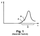
図1に、圧着プロセスにおける力対時間曲線の一例を示す。このグラフは、第1圧着ツールを第2圧着ツールに対し移動させる際に経過する時間tに沿い、それら2個の圧着ツール間に作用する力Fをプロットしたものである。 FIG. 1 shows an example of a force versus time curve in the crimping process. This graph is a plot of the force F acting between the two crimping tools along the time t that elapses when the first crimping tool is moved relative to the second crimping tool.
明瞭に読み取れるように、力Fはある時点、即ち両圧着ツールがワークピースに接した時点から比較的急峻に強まっている。逆に、最大値を迎えた時点、即ち両圧着ツールが互いに退き始めた時点からは、力Fが急峻に弱まっていく。これは、圧着プロセスでよく見られるタイプの力対時間曲線である。実際には、どのような種類の電極にワイヤを押圧するか等にもよるので、力対時間曲線がこの例とは大きく異なる場合もある。 As can be clearly seen, the force F increases relatively steeply from a certain point, that is, from the point where both crimping tools are in contact with the workpiece. On the contrary, the force F sharply weakens from the time when the maximum value is reached, that is, from the time when both the crimping tools start to retract. This is a type of force versus time curve commonly found in the crimping process. Actually, the force vs. time curve may differ greatly from this example because it depends on what kind of electrode the wire is pressed against.
図中の力対時間曲線には平坦領域A及び極小領域Bが現れている。これらが発生した原因は、2個のベアリング間でベアリング面同士の接触タイミング及び接触に至るF値が異なる点にある。領域Aではこの現象が力Fの一定化となって現れる一方、領域Bの弱まりとして現れている。いわば、領域Bではベアリング面同士が“弾き”あっている。 A flat region A and a minimal region B appear in the force versus time curve in the figure. The reason for these occurrences is that the contact timing between the bearing surfaces and the F value leading to contact differ between the two bearings. In the region A, this phenomenon appears as a constant force F, while it appears as a weakening of the region B. In other words, in the region B, the bearing surfaces are “played”.
こうした力対時間曲線のうち圧着プロセスの評価に使用されるのは、概ねその中央部のみである。何故なら、圧着プロセスの始期及び終期では力のばらつき・拡がりが大きく、圧着接合の質を評価するのにあまり役立たないからである。この図では、役立つ領域が参照符号Dで示されている。 Of these force versus time curves, only the central part is used for evaluating the crimping process. This is because there is a large variation and spread of force at the beginning and end of the crimping process, which is not very useful for evaluating the quality of crimp bonding. In this figure, a useful area is indicated by the reference symbol D.
問題なのは、圧着接合の質を調べるのに使用される領域D内の力対時間曲線に、圧着プロセスではなくベアリング遊びに由来する領域A,Bが図示の如く生じうることである。こうした領域は、自明な通り、圧着接合の質を評価する上で大きな妨げになりうる。状況によっては、ベアリング遊び由来の領域A,Bにて力対時間曲線が許容公差帯から外れてしまい、圧着接合の質が使用不能であると誤評定されることもあり得る。 The problem is that regions A and B originating from bearing play rather than the crimping process can occur in the force versus time curve in region D used to examine the quality of the crimp joint as shown. As is obvious, these areas can be a major obstacle to assessing the quality of crimp joints. Depending on the situation, the force vs. time curve may deviate from the tolerance zone in the areas A and B derived from bearing play, and the quality of the crimp joint may be misclassified as unusable.
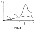
図2に、図1に示したそれと同様の状況だが、第1・第2圧着ツール間に本発明に従い圧着力と同方向の先行力を圧着プロセス開始前から作用させている例を示す。この例では、線形的な特性曲線Cを呈するバネを用い先行力を作用させている。圧着ツールが退き始めた時点で合計の力Fは最大になり、その後はバネ特性曲線Cも下降を示している。 FIG. 2 shows an example in which the preceding force in the same direction as the crimping force is applied between the first and second crimping tools before the start of the crimping process, although the situation is similar to that shown in FIG. In this example, a leading force is applied using a spring exhibiting a linear characteristic curve C. When the crimping tool starts to retract, the total force F becomes maximum, and thereafter, the spring characteristic curve C also shows a decrease.
この図に明示の通り、力対時間曲線の不連続部即ち領域A,Bは実際の圧着プロセスに対し大分先行している。即ち、ベアリングに備わるベアリング面の働きで平坦領域Aが生じてから、それらベアリング面が互いに駆動されて圧着プロセスが始まるまでに、大分時間が経過している。そのため、力対時間曲線のうち圧着プロセスを特徴付ける領域Dはベアリング遊びの影響を受けず、圧着接合の質を評価する際そのまま使用することができる。 As clearly shown in this figure, the discontinuities of the force vs. time curve, areas A and B, are largely ahead of the actual crimping process. That is, much time has passed after the flat area A is generated by the action of the bearing surface provided in the bearing and before the bearing surface is driven to start the crimping process. Therefore, the region D characterizing the crimping process in the force versus time curve is not affected by bearing play and can be used as it is when evaluating the quality of the crimping joint.
通常は、図示例のように、ベアリング遊びに由来する異常が領域Dに及ばないようにするだけで十分なことが多い。ベアリング遊びに由来する異常が圧着プロセス全体に及ばないようにする必要はほとんどない。 Usually, it is often sufficient only to prevent the abnormality derived from the bearing play from reaching the region D as in the illustrated example. There is little need to ensure that anomalies resulting from bearing play do not reach the entire crimping process.
図3に、図2に示したそれと同様の状況だがバネ特性曲線Cが異なる例を示す。この曲線Cは、最初に急峻に立ち上がった後、横方向に延びている。こうした曲線Cは、例えば、圧力リリーフバルブ付のガス圧バネで得ることができる。この種のガス圧バネでは、内圧ひいては外部に作用する力が最初は急峻に強まり、圧力リリーフバルブが開いた後は一定値に保たれる。曲線Cは、圧力リリーフバルブが開く圧力を適宜調整することで、様々な条件に対し好適に整合させることができる。無論、逆行バネ特性曲線を呈する他種のバネも遜色なく使用することができる。 FIG. 3 shows an example similar to that shown in FIG. 2, but with a different spring characteristic curve C. This curve C first rises steeply and then extends in the lateral direction. Such a curve C can be obtained, for example, by a gas pressure spring with a pressure relief valve. In this type of gas pressure spring, the internal pressure and thus the force acting on the outside increases sharply at first, and is maintained at a constant value after the pressure relief valve is opened. The curve C can be suitably matched to various conditions by appropriately adjusting the pressure at which the pressure relief valve opens. Of course, other types of springs exhibiting a retrograde spring characteristic curve can also be used.
ベアリング面同士が早期に接触するため、図示の通り、領域A,Bは図の左寄りに生じる。力対時間曲線のうち圧着プロセスを特徴付ける領域Dは、ベアリング遊びの影響を全く受けていない。従って、圧着接合の質を更に好適に評価することができる。 Since the bearing surfaces come into contact with each other at an early stage, regions A and B are formed on the left side of the drawing as shown in the figure. The region D characterizing the crimping process of the force versus time curve is not affected at all by bearing play. Accordingly, it is possible to more suitably evaluate the quality of the pressure bonding.
図4に、図3に示したそれと似た状況だが、先行力を発生する手段として能動的なアクチュエータを使用している例を示す。合計の力Fは、図3に示したそれと同じく最初に急に強まり、その後は一定値を保っている。図3に示した例との違いは、破線の如く圧着プロセスが始まった後も力Fが一定値を保つ点である。こうした動作は、力Fの計測値が一定になるよう先行力を弱めることで発生する。これは力Fに対する制御である。圧着プロセスの進行につれ力Fが強まったなら先行力はその分弱める。 FIG. 4 shows an example similar to that shown in FIG. 3, but using an active actuator as a means for generating a leading force. The total force F suddenly increases at the same time as that shown in FIG. 3, and then remains constant. The difference from the example shown in FIG. 3 is that the force F maintains a constant value even after the crimping process is started as indicated by a broken line. Such an operation occurs by weakening the leading force so that the measured value of the force F becomes constant. This is a control for the force F. If the force F increases as the crimping process progresses, the leading force decreases accordingly.
先行力にはそれ以上弱められない限界があるため、圧着プロセスの進行に伴う力の強まりにつれ、合計の力Fを一定に保つことができなくなり、その時点からは力Fが強まっていく(先行力印加用のアクチュエータとして先行力を逆方向にも印加可能なものを使用してもよい)。この領域では、当然、力対時間曲線が図1に示したそれと似たものになる。その後、力Fの強さが先行力の最大値を下回ると先行力が徐々に強まるので、圧着プロセスの終期には平坦領域が力対時間曲線に再び現れる。 Since the leading force has a limit that cannot be further reduced, the total force F cannot be kept constant as the force increases with the progress of the crimping process. An actuator that can apply a leading force in the reverse direction may be used as an actuator for applying force. In this region, of course, the force versus time curve will be similar to that shown in FIG. Thereafter, when the strength of the force F falls below the maximum value of the preceding force, the leading force gradually increases, so that at the end of the crimping process, a flat region reappears on the force versus time curve.
印加されている先行力は随時計測可能であるので、図4中に実線で示した力対時間曲線からその結果を差し引くことで、先行力抜きでの力対時間曲線を求めることができる。こうして求まる圧着プロセス実行時力対時間曲線は、破線で示す如く図1に示したものに似ているが、前掲のベアリング遊び由来領域A,Bは、圧着プロセス実行期間から見てグラフ上で遙か左即ち遙か古くに位置しているため現れてこない。 Since the applied preceding force can be measured at any time, a force versus time curve without preceding force can be obtained by subtracting the result from the force versus time curve shown by the solid line in FIG. The crimping process execution force vs. time curve thus obtained is similar to that shown in FIG. 1 as indicated by the broken line, but the bearing play-derived regions A and B described above are on the graph as viewed from the crimping process execution period. Or it does not appear because it is located on the left, i.e., vase.
本発明をこうした形態で実行することで、先行力を印加しているにもかかわらず、力対時間曲線における力の最強値が図1に示した先行力無しでの値を上回らないようにすることができる。図2及び図3に示した実施形態と異なり、先行力の印加によって圧着プレスの負荷が増すことはない。 By carrying out the present invention in such a manner, the strongest value of the force in the force vs. time curve does not exceed the value without the preceding force shown in FIG. 1 even though the preceding force is applied. be able to. Unlike the embodiment shown in FIG. 2 and FIG. 3, the load on the crimping press does not increase by applying the leading force.
図4に示した実施形態で使用可能なアクチュエータとしては、その圧力を能動的に制御可能な気圧乃至液体圧シリンダを例示することができる。先行力を可調印加することが可能な他種アクチュエータを使用することもできる。 As an actuator that can be used in the embodiment shown in FIG. 4, there can be exemplified an air pressure or a liquid pressure cylinder whose pressure can be actively controlled. It is also possible to use other types of actuators that can apply a leading force in an adjustable manner.
ドライブに備わるベアリング面同士が遊び無しで接しているか否かを圧着プロセス実行中に判別するのも有益である。力対時間曲線に異常、例えば平坦領域Aや極小領域Bが現れるとこの判別の結果が否定的になるので、付勢手段、先行力又はその双方の調整を通じ圧着プロセス実行中にベアリング面同士の接触に係る遊びを解消させ、異常が生じないようにすることができる。先行力をどのような強さにすれば異常が生じない強さかは特定することができる。 It is also useful to determine during the crimping process whether the bearing surfaces of the drive are in contact without play. If the force vs. time curve appears abnormal, for example, the flat area A or the minimum area B, the result of this determination becomes negative. It is possible to eliminate the play related to the contact and prevent the abnormality from occurring. It is possible to specify the strength of the leading force that does not cause an abnormality.
図5に、本発明の一実施形態に係る圧着プレス1を示す。このプレス1は、マシンフレーム2、ドライブシャフトベアリング3内に実装されたドライブシャフト4、そのドライブシャフト4に連結されたカム5、そのカム5に連結された連結ロッド6、連結ロッドベアリング7を介しカム5に連結されたプレスキャリッジ8、並びにそのプレスキャリッジ8の可動装着先たるキャリッジガイド9a,9bを備えている。
FIG. 5 shows a crimping press 1 according to an embodiment of the present invention. The press 1 includes a
マシンフレーム2には、圧着装置10及びその第1圧着ツール11も連結されている。この例ではマシンフレーム2に対し第1圧着ツール11が固定実装されているが、これは必須な事柄ではない。逆に、マシンフレーム2に対し可動となるよう第1圧着ツール11を実装してもかまわない。
A crimping device 10 and a first crimping tool 11 thereof are also connected to the
プレスキャリッジ8は、圧着力センサ12が付設された可撓梁を介し第2圧着ツール13にも連結されているので、マシンフレーム2に対し運動させることができる。
Since the
そして、圧着プレス1は、キャリッジ側のホルダ14、フレームに固定されたホルダ16、並びにキャリッジ側ホルダ14・フレーム側固定ホルダ16間に位置する弾性要素15を備えている。
The crimping press 1 includes a carriage-
図5に示した圧着プレス1は次のように稼働する。 The crimping press 1 shown in FIG. 5 operates as follows.
まず、ドライブシャフト4を介しカム5を駆動するとその動力が連結ロッド6を介しプレスキャリッジ8へと伝わる。圧着プロセス実行中は、プレスキャリッジ8の下降によって2個の圧着ツール11,13が相互接近方向に移動する。圧着ツール11・13間に作用する力は圧着力センサ12によって連続計測される。
First, when the
圧着ツール11・13間には、弾性要素15によって、圧着プロセス実行以前から作用するよう先行力も印加される。先行力は、ドライブトレインに備わる諸ベアリングのベアリング面同士を接触させる。この接触は、図示例の場合、カム5・連結ロッド6間ベアリング及び連結ロッド6・プレスキャリッジ8間ベアリングで生じる。
A preceding force is also applied between the crimping
プレスキャリッジ8を下降させていくと、いずれ、第2圧着ツール13がワークピース(図示せず)に接触してあらゆるベアリング遊びが抑圧され、圧着プロセス実行中に力計測上非常に弱い影響を及ぼす程度又はそうした影響すらない程度に至る。
As the
加圧用の弾性要素15に代え又は加え、引張用の弾性要素18をフレーム側固定ホルダ17・キャリッジ側ホルダ14間に設けてもよい。
Instead of or in addition to the pressing
その弾性要素15又は18としては、力対時間曲線が例えば図2及び図3に示した曲線になるよう、例えば弦巻バネ、竹の子バネ、板バネ、円板バネ、ガス圧バネ、エラストマバネ又は繊維複合材製のバネを使用することができる。
As the
弾性要素15,18に代え又は加えアクチュエータを設けることもできる。例えば、その圧力を能動制御可能な気体圧シリンダをキャリッジ側ホルダ14・フレーム側固定ホルダ16間に設け、力対時間曲線を例えば図4に示したものにすることができる。
An actuator can be provided instead of or in addition to the
弾性要素やアクチュエータを図示部位以外の部位に設けることも一考に値する。例えば、圧着ツール11,13の直間に配置してもよい。圧着プレス1上に複数個の付勢手段を配置すること、例えば連結ロッド6・カム5間及び連結ロッド6・プレスキャリッジ8間に併設することも可能である。本発明には、このほか、本件技術分野で習熟を積まれた方々(いわゆる当業者)が日常活動の範囲内で取得しうる知見に基づく構成も包含される。
It is also worth considering that an elastic element or an actuator is provided in a region other than the illustrated region. For example, you may arrange | position between the crimping
そして、図1〜図4に関する説明では力対時間曲線を使用したが、力対経路曲線でも本発明を遜色なく実施することができる。図示した圧着プレス1は本発明の実施に適する構成の一例、多々ある可能例の一つに過ぎないので、本発明の適用範囲がこれを以て限定されるものと解されるべきではない。無論、図示した実施形態については様々に結合乃至変形させることができる。例えば、バネとアクチュエータを組み合わせることで図2の着想及び図4の着想を同時に体現させるようにしてもよい。加えて、図中の装置で使用されている部材は、それ自体、独立した発明の基礎をなしうる。 1 to 4, the force vs. time curve is used, but the present invention can be implemented even with the force vs. path curve. The illustrated crimping press 1 is merely one example of a configuration suitable for the implementation of the present invention, and is only one of many possible examples, so the scope of the present invention should not be construed as being limited thereby. Of course, the illustrated embodiments can be combined or modified in various ways. For example, the idea of FIG. 2 and the idea of FIG. 4 may be embodied simultaneously by combining a spring and an actuator. In addition, the components used in the apparatus in the figure can themselves form the basis of an independent invention.
A 平坦領域、B 極小領域、C バネ特性曲線、D 質を決定づける領域、F 力、t 時間、1 圧着プレス、2 マシンフレーム、3 ドライブシャフトベアリング、4 ドライブシャフト、5 カム、6 連結ロッド、7 連結ロッドベアリング、8 プレスキャリッジ、9a,9b キャリッジガイド、10 圧着装置、11 第1圧着ツール、12 圧着力センサ、13 第2圧着ツール、14 キャリッジ側ホルダ、15 加圧モード用弾性要素、16 加圧モード用フレーム側固定ホルダ、17 引張モード用フレーム側固定ホルダ、18 引張モード用弾性要素。 A flat area, B minimal area, C spring characteristic curve, D quality determining area, F force, t time, 1 crimping press, 2 machine frame, 3 drive shaft bearing, 4 drive shaft, 5 cam, 6 connecting rod, 7 Connecting rod bearing, 8 press carriage, 9a, 9b carriage guide, 10 crimping device, 11 first crimping tool, 12 crimping force sensor, 13 second crimping tool, 14 carriage-side holder, 15 pressure mode elastic element, 16 pressurization Frame side fixed holder for pressure mode, 17 Frame side fixed holder for tension mode, 18 Elastic element for tension mode.
Claims (8)
第1圧着ツール(11)に対して可動な第2圧着ツール(13)と、
圧着プロセス(D)実行中に第1圧着ツール(11)・第2圧着ツール(13)間に圧着力を作用させるドライブ(3〜8)と、
を備える圧着プレス(1)であって、
第1、第2の圧着ツール(11,13)が互いに離間する方向に働くよう圧着プロセス(D)開始前に作用し始める力即ち先行力を第1圧着ツール(11)・第2圧着ツール(13)間に作用させる付勢手段(15,18)と、
ドライブ(3〜8)に備わるベアリング同士が遊びなく接触していることを圧着プロセス(D)実行中に確認する手段と、
否定的な確認結果に応じ付勢手段(15,18)を調整することで圧着プロセス(D)実行中にベアリング面同士を遊びなく接触させる手段と、
を備えることを特徴とする圧着プレス。 A first crimping tool (11);
A second crimping tool (13) movable relative to the first crimping tool (11);
A drive (3-8) for applying a crimping force between the first crimping tool (11) and the second crimping tool (13) during the crimping process (D),
A crimping press (1) comprising:
The first crimping tool (11) and the second crimping tool (the first crimping tool (11) and the second crimping tool (the leading force) start to act before the crimping process (D) starts so that the first and second crimping tools (11, 13) work in directions away from each other. 13) biasing means (15, 18) acting between ,
Means for confirming that the bearings of the drives (3 to 8) are in contact with each other without play during the crimping process (D);
Means for adjusting the biasing means (15, 18) according to the negative confirmation result to bring the bearing surfaces into contact with each other without play during the crimping process (D);
A crimping press characterized by comprising:
マシンフレーム(2)であって、第1及び第2圧着ツール(11,13)の一方又は双方が当該マシンフレーム(2)に対して可動なマシンフレーム(2)を備え、
付勢手段(15,18)が、マシンフレーム(2)と第1及び第2圧着ツール(11,13)のうち一方又は双方との間に先行力を作用させることを特徴とする圧着プレス。 A 1 Symbol placement of the crimping press according to claim (1),
A machine frame (2), wherein one or both of the first and second crimping tools (11, 13) comprises a machine frame (2) movable relative to the machine frame (2);
A pressing press, wherein the biasing means (15, 18) applies a leading force between the machine frame (2) and one or both of the first and second pressing tools (11, 13).
第1圧着ツール(11)・第2圧着ツール(13)間に作用する力(F)を第1圧着ツール(11)・第2圧着ツール(13)間の距離、時間(t)又はその双方に関連付けて検知する検知手段を備え、
その検知手段が、圧着プロセス(D)実行中に記録された力対経路曲線、力対時間曲線又はその双方からドライブ(3〜8)におけるベアリング遊びの影響を差し引いた曲線(A,B)を求めることを特徴とする圧着プレス。 A crimping press (1) according to any one of claims 1 to 6,
The force (F) acting between the first crimping tool (11) and the second crimping tool (13) is the distance between the first crimping tool (11) and the second crimping tool (13), time (t) or both. A detection means for detecting in association with
The detection means obtains curves (A, B) obtained by subtracting the influence of bearing play in the drive (3-8) from the force vs. path curve, force vs. time curve or both recorded during the crimping process (D). A crimping press characterized by the demand.
第1圧着ツール(11)・第2圧着ツール(13)間に作用する力(F)を検知する手段と、
圧着プロセス(D)中に先行力を弱める手段と、
を備えることを特徴とする圧着プレス。 A crimping press (1) according to any one of claims 1 to 7 ,
Means for detecting a force (F) acting between the first crimping tool (11) and the second crimping tool (13);
Means for weakening the leading force during the crimping process (D);
A crimping press characterized by comprising:
Applications Claiming Priority (5)
| Application Number | Priority Date | Filing Date | Title |
|---|---|---|---|
| CHCH00530/10 | 2010-04-13 | ||
| CH5302010 | 2010-04-13 | ||
| EP10160378A EP2378615A1 (en) | 2010-04-13 | 2010-04-19 | Crimp press |
| EP10160378.5 | 2010-04-19 | ||
| PCT/IB2011/051576 WO2011128844A1 (en) | 2010-04-13 | 2011-04-12 | Crimping press |
Publications (3)
| Publication Number | Publication Date |
|---|---|
| JP2013524475A JP2013524475A (en) | 2013-06-17 |
| JP2013524475A5 JP2013524475A5 (en) | 2014-05-29 |
| JP5916706B2 true JP5916706B2 (en) | 2016-05-11 |
Family
ID=43012767
Family Applications (1)
| Application Number | Title | Priority Date | Filing Date |
|---|---|---|---|
| JP2013504380A Active JP5916706B2 (en) | 2010-04-13 | 2011-04-12 | Crimping press |
Country Status (10)
| Country | Link |
|---|---|
| US (1) | US9300102B2 (en) |
| EP (2) | EP2378615A1 (en) |
| JP (1) | JP5916706B2 (en) |
| KR (1) | KR101801997B1 (en) |
| CN (1) | CN102859812B (en) |
| BR (1) | BR112012021935A2 (en) |
| CA (1) | CA2789636C (en) |
| MX (1) | MX2012009827A (en) |
| RU (1) | RU2012148043A (en) |
| WO (1) | WO2011128844A1 (en) |
Families Citing this family (8)
| Publication number | Priority date | Publication date | Assignee | Title |
|---|---|---|---|---|
| EP2378615A1 (en) | 2010-04-13 | 2011-10-19 | Schleuniger Holding AG | Crimp press |
| JP2013105560A (en) * | 2011-11-11 | 2013-05-30 | Furukawa Electric Co Ltd:The | Terminal crimping device |
| JP5959005B2 (en) * | 2012-12-27 | 2016-08-02 | 矢崎総業株式会社 | Pressure sensor mounting structure of terminal crimping device and crimping force inspection method using the same |
| CN104158057A (en) * | 2014-08-22 | 2014-11-19 | 苏州昌飞自动化设备厂 | Cable claw low butting mechanism of double-lug flat cable copper joint assembling machine |
| CN112106264B (en) * | 2018-04-24 | 2023-03-24 | 施洛伊尼格股份公司 | Tool changer, machining tool, and method of changing tool |
| DE102019101016A1 (en) * | 2019-01-16 | 2020-07-16 | Harting Electric Gmbh & Co. Kg | Method and device for checking the quality of a crimp |
| CN112453898B (en) * | 2020-12-12 | 2022-10-11 | 江西洪都航空工业集团有限责任公司 | Sprinkler spring equipment |
| CN114512872A (en) * | 2022-03-04 | 2022-05-17 | 东莞市锐升电线电缆有限公司 | Arrange wiring wire stripping and beat terminal equipment |
Family Cites Families (62)
| Publication number | Priority date | Publication date | Assignee | Title |
|---|---|---|---|---|
| US3955044A (en) * | 1970-12-03 | 1976-05-04 | Amp Incorporated | Corrosion proof terminal for aluminum wire |
| US4285228A (en) * | 1979-08-20 | 1981-08-25 | Anchor Coupling Co., Inc. | Crimping machine for hose assembly |
| US4828516A (en) * | 1983-12-30 | 1989-05-09 | Amp Incorporated | Crimped electrical connection and crimping dies therefore |
| US4534107A (en) * | 1984-03-09 | 1985-08-13 | Amp Incorporated | Wire insertion and terminal crimping tool |
| US4576032A (en) * | 1984-07-30 | 1986-03-18 | Amp Incorporated | Crimping press capable of crimping terminals onto a range of wire sizes |
| US4805278A (en) * | 1986-07-10 | 1989-02-21 | Panduit Corp. | Terminal strip applicator |
| JPS63198268A (en) * | 1987-02-12 | 1988-08-16 | 矢崎総業株式会社 | Wire compression bonding construction for connector terminal |
| US4914602A (en) * | 1987-05-13 | 1990-04-03 | Furukawa Electric Co., Ltd. | Method for detecting the molding defectiveness of a press-molded workpiece and a terminal press-bonding apparatus utilizing the same |
| US4829804A (en) * | 1987-10-13 | 1989-05-16 | Sps Technologies, Inc. | Tooling for crimping eyelet-type inserts |
| DE3808986A1 (en) * | 1988-03-17 | 1989-09-28 | Juergenhake Bernhard | METHOD AND TOOL FOR CRIMPING CONTACT PARTS ON ELECTRICAL CABLES |
| US4896419A (en) * | 1988-03-17 | 1990-01-30 | Bernhard Jurgenhake | Apparatus and process for fastening contact pieces to electrical leads |
| DE8805338U1 (en) * | 1988-04-22 | 1988-06-09 | Wesma Kabelverbindungsmaschinen Gmbh, 5470 Andernach, De | |
| US4970889A (en) * | 1989-05-12 | 1990-11-20 | Amp Incorporated | Crimping machine having improved adjusting system |
| US4964200A (en) * | 1989-08-22 | 1990-10-23 | Amp Incorporated | Lead making machine having improved crimping presses and actuating mechanism |
| FR2651384B1 (en) * | 1989-08-31 | 1991-11-29 | Aerospatiale | DEVICE FOR CRIMPING CONNECTION ELEMENTS ON ELECTRICAL CONDUCTORS AND AUTOMATIC CRIMPING SYSTEM COMPRISING SUCH A DEVICE. |
| US5092026A (en) * | 1989-09-22 | 1992-03-03 | Molex Incorporated | Crimp height monitor |
| US5271254A (en) * | 1989-12-05 | 1993-12-21 | The Whitaker Corporation | Crimped connector quality control method apparatus |
| DE4040410C1 (en) * | 1989-12-21 | 1991-11-07 | Bernhard Dr.-Ing. 4782 Erwitte De Juergenhake | Tooling for crimping electrical connectors - comprises crank press with spring-loaded plunger, connected torsionally to transducer providing displacement measurement |
| US5105648A (en) * | 1990-02-16 | 1992-04-21 | Rostra Tool Company | Molded lightweight handtool with structural insert |
| US5197186A (en) * | 1990-05-29 | 1993-03-30 | Amp Incorporated | Method of determining the quality of a crimped electrical connection |
| US5275032A (en) * | 1990-05-30 | 1994-01-04 | The Whitaker Corporation | Method and apparatus for controlling the crimp height of crimped electrical connections |
| US5101651A (en) * | 1991-02-22 | 1992-04-07 | Amp Incorporated | Apparatus for determining the force imposed on a terminal during crimping thereof |
| US5123165A (en) * | 1991-03-21 | 1992-06-23 | Amp Incorporated | Method of determining the crimp height of a crimped electrical connection |
| US5307432A (en) * | 1992-10-09 | 1994-04-26 | Luxtec Corporation | Crimped light source terminations |
| US5417461A (en) * | 1993-08-25 | 1995-05-23 | S&H Fabricating And Engineering, Inc. | Tube-to-hose coupling (crimp-sert) and method of making same |
| DE4337796A1 (en) | 1993-11-05 | 1995-05-11 | Abstron Electronics Gmbh | Method for monitoring the quality of crimped joints |
| US5727409A (en) * | 1994-12-28 | 1998-03-17 | Yazaki Corporation | Method of controlling a terminal crimping apparatus |
| JPH08236253A (en) * | 1994-12-28 | 1996-09-13 | Yazaki Corp | Controlling method for contact crimping apparatus |
| US5937505A (en) * | 1995-03-02 | 1999-08-17 | The Whitaker Corporation | Method of evaluating a crimped electrical connection |
| GB9512147D0 (en) | 1995-06-15 | 1995-08-16 | Amp Gmbh | Force sensor for crimp press |
| JPH097728A (en) * | 1995-06-21 | 1997-01-10 | Kyoritsu Hiparts Kk | Simplified terminal crimp device |
| JPH09168805A (en) * | 1995-10-20 | 1997-06-30 | Ishikawajima Harima Heavy Ind Co Ltd | Edging press |
| JP3156841B2 (en) * | 1996-06-12 | 2001-04-16 | 矢崎総業株式会社 | Control method of terminal crimping device |
| JPH1050449A (en) * | 1996-07-31 | 1998-02-20 | Yazaki Corp | Terminal crimp device |
| US5841675A (en) * | 1997-02-10 | 1998-11-24 | Oes, Inc. | Method and apparatus for monitoring quality of electrical wire connections |
| CH693550A5 (en) * | 1997-06-30 | 2003-09-30 | Komax Holding Ag | Crimping device and method for its operation. |
| US5850685A (en) * | 1997-07-29 | 1998-12-22 | The Whitaker Corporation | Manual cycling mechanism for a magnetically powered terminating machine |
| DE59806982D1 (en) | 1997-09-11 | 2003-02-27 | Komax Holding Ag Dierikon | Method for determining the quality of a crimp connection |
| US5845528A (en) * | 1997-10-07 | 1998-12-08 | Artos Engineering Company | Apparatus for crimping terminals on an electrical conductor |
| US5920975A (en) * | 1997-11-03 | 1999-07-13 | Advanced Cardiovascular Systems, Inc. | Stent crimping tool and method of use |
| US6047579A (en) * | 1998-04-17 | 2000-04-11 | The Minster Machine Company | RF tag attached to die assembly for use in press machine |
| DE19843156A1 (en) * | 1998-09-21 | 2000-04-20 | Sle Electronic Gmbh | Process for quality assurance of crimp connections produced in a crimping device, as well as crimping tool and crimping device |
| GB9901641D0 (en) * | 1999-01-26 | 1999-03-17 | Raychem Ltd | Crimping composite electrical insulators |
| US6119502A (en) * | 1999-02-22 | 2000-09-19 | Buchmayer; Ernst | Hand held compressed air powered crimping tool to secure ring tongue terminals to stripped electrical wire ends, and to secure butt splices to join two electrical wire ends |
| US6301777B1 (en) * | 1999-11-16 | 2001-10-16 | Autoliv Asp, Inc. | Applicator die for wire-to-terminal assembly |
| EP1143579A1 (en) * | 2000-04-04 | 2001-10-10 | Pawo Systems A.G. | Contact working station |
| EP1143578A1 (en) * | 2000-04-04 | 2001-10-10 | Pawo Systems A.G. | Contact working station |
| CN2440278Y (en) * | 2000-08-10 | 2001-07-25 | 黄金定 | SMD pneumatic double-side terminal automatic pushing-through machine |
| US6527016B2 (en) * | 2001-02-28 | 2003-03-04 | General Binding Corporation | Automated spiral binding machine |
| JP4031214B2 (en) * | 2001-03-19 | 2008-01-09 | 矢崎総業株式会社 | Terminal crimping state identification method |
| DE10144322A1 (en) | 2001-09-10 | 2003-03-27 | Delphi Tech Inc | Method of making an electrical insulation displacement connection |
| JP4074849B2 (en) * | 2003-12-02 | 2008-04-16 | 株式会社小寺電子製作所 | Terminal crimping device |
| JP2005285343A (en) * | 2004-03-26 | 2005-10-13 | Jst Mfg Co Ltd | Apparatus and method for manufacturing electric wire wth terminal |
| JP4699263B2 (en) * | 2006-04-03 | 2011-06-08 | 住友重機械テクノフォート株式会社 | Crank press |
| JP4636013B2 (en) * | 2006-12-18 | 2011-02-23 | 住友電装株式会社 | Terminal crimping device |
| FR2916091B1 (en) * | 2007-05-11 | 2009-07-17 | Eurocopter France | IMPROVEMENT IN INTEGRATED CONTROL CRIMPING SYSTEMS. |
| CN101442175A (en) * | 2007-11-23 | 2009-05-27 | 北京天泽电力器材有限公司 | Press pinchers for conductor and cable |
| US8746026B2 (en) * | 2008-10-02 | 2014-06-10 | Komax Holding Ag | Method for determining the quality of a crimped connection between a conductor and a contact |
| US8336351B2 (en) * | 2009-06-03 | 2012-12-25 | Delphi Technologies, Inc. | Apparatus and methods that apply a press force including a separately applied core crimp force |
| EP2378615A1 (en) | 2010-04-13 | 2011-10-19 | Schleuniger Holding AG | Crimp press |
| US9331447B2 (en) * | 2010-12-07 | 2016-05-03 | Tyco Electronics Corporation | Crimping apparatus having a crimp quality monitoring system |
| US8671559B2 (en) * | 2011-04-27 | 2014-03-18 | GM Global Technology Operations LLC | System for joining stator wires |
-
2010
- 2010-04-19 EP EP10160378A patent/EP2378615A1/en not_active Withdrawn
-
2011
- 2011-04-12 WO PCT/IB2011/051576 patent/WO2011128844A1/en active Application Filing
- 2011-04-12 CN CN201180016813.4A patent/CN102859812B/en active Active
- 2011-04-12 JP JP2013504380A patent/JP5916706B2/en active Active
- 2011-04-12 CA CA2789636A patent/CA2789636C/en active Active
- 2011-04-12 BR BR112012021935A patent/BR112012021935A2/en not_active IP Right Cessation
- 2011-04-12 KR KR1020127026388A patent/KR101801997B1/en active IP Right Grant
- 2011-04-12 RU RU2012148043/07A patent/RU2012148043A/en unknown
- 2011-04-12 MX MX2012009827A patent/MX2012009827A/en not_active Application Discontinuation
- 2011-04-12 EP EP11722534.2A patent/EP2559116B1/en active Active
-
2012
- 2012-10-12 US US13/650,150 patent/US9300102B2/en active Active
Also Published As
| Publication number | Publication date |
|---|---|
| CN102859812B (en) | 2016-01-20 |
| EP2559116B1 (en) | 2017-11-01 |
| EP2559116A1 (en) | 2013-02-20 |
| CA2789636C (en) | 2018-12-18 |
| JP2013524475A (en) | 2013-06-17 |
| CA2789636A1 (en) | 2011-10-20 |
| WO2011128844A1 (en) | 2011-10-20 |
| MX2012009827A (en) | 2012-09-12 |
| CN102859812A (en) | 2013-01-02 |
| US20130055563A1 (en) | 2013-03-07 |
| BR112012021935A2 (en) | 2016-05-31 |
| EP2378615A1 (en) | 2011-10-19 |
| US9300102B2 (en) | 2016-03-29 |
| KR20130064726A (en) | 2013-06-18 |
| RU2012148043A (en) | 2014-05-20 |
| KR101801997B1 (en) | 2017-11-27 |
Similar Documents
| Publication | Publication Date | Title |
|---|---|---|
| JP5916706B2 (en) | Crimping press | |
| JP5196642B2 (en) | Resistance welding method monitoring method and apparatus for carrying out the method | |
| US20080177512A1 (en) | Online determination of the quality characteristics for punch riveting and clinching | |
| JP5777718B2 (en) | Welding head with force sensor, spring and adjusting member | |
| EP2590762B1 (en) | Joining method | |
| RU2696116C2 (en) | Radial press | |
| US20080289169A1 (en) | Method and apparatus for joining plates | |
| US11135637B2 (en) | Method for determining the quality of a joint, and control method for a process of joining a plurality of metal sheets by means of a joining device | |
| JP6275859B2 (en) | Ultrasonic machining device with force sensor | |
| JP5223283B2 (en) | Chip dress state monitoring method, monitoring device, and spot welding system | |
| US20120271581A1 (en) | Process monitoring for high-speed joining | |
| CN105738202A (en) | Method of conducting strength detection on guide plate welding spot with pressure testing machine | |
| JP2016160086A (en) | Man conveyor device and tension adjustment method of moving rail of the man conveyor device | |
| US20140173869A1 (en) | Method for monitoring a joining process | |
| KR20090075513A (en) | Vertical resistance welding apparatus | |
| KR20150127979A (en) | The seat of the ball joint ball and the clearance inspection apparatus | |
| KR20180059943A (en) | A friction stir spot joining device and a friction stir spot joining method | |
| KR20190077503A (en) | Method of making CTOD test piece and jig for plastic deformation adjustment | |
| JP2008213070A (en) | Press-in device and method | |
| KR20090071133A (en) | Grip device for testing tension of welded materials | |
| JP7416562B2 (en) | Dual Cam Servo Welding Splicer | |
| KR102211554B1 (en) | Track bush for crawler track | |
| JP7056451B2 (en) | Resistance welding equipment | |
| JP2011079040A (en) | Toggle pressurizing unit | |
| JP2023112752A (en) | Electrode tip shaping device |
Legal Events
| Date | Code | Title | Description |
|---|---|---|---|
| A521 | Request for written amendment filed |
Free format text: JAPANESE INTERMEDIATE CODE: A523 Effective date: 20140409 |
|
| A621 | Written request for application examination |
Free format text: JAPANESE INTERMEDIATE CODE: A621 Effective date: 20140409 |
|
| A977 | Report on retrieval |
Free format text: JAPANESE INTERMEDIATE CODE: A971007 Effective date: 20150122 |
|
| A131 | Notification of reasons for refusal |
Free format text: JAPANESE INTERMEDIATE CODE: A131 Effective date: 20150203 |
|
| A521 | Request for written amendment filed |
Free format text: JAPANESE INTERMEDIATE CODE: A523 Effective date: 20150501 |
|
| A131 | Notification of reasons for refusal |
Free format text: JAPANESE INTERMEDIATE CODE: A131 Effective date: 20151110 |
|
| A521 | Request for written amendment filed |
Free format text: JAPANESE INTERMEDIATE CODE: A523 Effective date: 20160209 |
|
| TRDD | Decision of grant or rejection written | ||
| A01 | Written decision to grant a patent or to grant a registration (utility model) |
Free format text: JAPANESE INTERMEDIATE CODE: A01 Effective date: 20160308 |
|
| A61 | First payment of annual fees (during grant procedure) |
Free format text: JAPANESE INTERMEDIATE CODE: A61 Effective date: 20160405 |
|
| R150 | Certificate of patent or registration of utility model |
Ref document number: 5916706 Country of ref document: JP Free format text: JAPANESE INTERMEDIATE CODE: R150 |
|
| R250 | Receipt of annual fees |
Free format text: JAPANESE INTERMEDIATE CODE: R250 |
|
| R250 | Receipt of annual fees |
Free format text: JAPANESE INTERMEDIATE CODE: R250 |
|
| S533 | Written request for registration of change of name |
Free format text: JAPANESE INTERMEDIATE CODE: R313533 |
|
| R350 | Written notification of registration of transfer |
Free format text: JAPANESE INTERMEDIATE CODE: R350 |
|
| R250 | Receipt of annual fees |
Free format text: JAPANESE INTERMEDIATE CODE: R250 |
|
| R250 | Receipt of annual fees |
Free format text: JAPANESE INTERMEDIATE CODE: R250 |
|
| R250 | Receipt of annual fees |
Free format text: JAPANESE INTERMEDIATE CODE: R250 |
|
| R250 | Receipt of annual fees |
Free format text: JAPANESE INTERMEDIATE CODE: R250 |