JP5914756B2 - Cleaning tool - Google Patents
Cleaning tool Download PDFInfo
- Publication number
- JP5914756B2 JP5914756B2 JP2015517854A JP2015517854A JP5914756B2 JP 5914756 B2 JP5914756 B2 JP 5914756B2 JP 2015517854 A JP2015517854 A JP 2015517854A JP 2015517854 A JP2015517854 A JP 2015517854A JP 5914756 B2 JP5914756 B2 JP 5914756B2
- Authority
- JP
- Japan
- Prior art keywords
- separator
- cleaning tool
- type cleaning
- cylinder
- recess
- Prior art date
- Legal status (The legal status is an assumption and is not a legal conclusion. Google has not performed a legal analysis and makes no representation as to the accuracy of the status listed.)
- Active
Links
Images


Classifications
-
- A—HUMAN NECESSITIES
- A47—FURNITURE; DOMESTIC ARTICLES OR APPLIANCES; COFFEE MILLS; SPICE MILLS; SUCTION CLEANERS IN GENERAL
- A47L—DOMESTIC WASHING OR CLEANING; SUCTION CLEANERS IN GENERAL
- A47L5/00—Structural features of suction cleaners
- A47L5/12—Structural features of suction cleaners with power-driven air-pumps or air-compressors, e.g. driven by motor vehicle engine vacuum
- A47L5/22—Structural features of suction cleaners with power-driven air-pumps or air-compressors, e.g. driven by motor vehicle engine vacuum with rotary fans
- A47L5/36—Suction cleaners with hose between nozzle and casing; Suction cleaners for fixing on staircases; Suction cleaners for carrying on the back
- A47L5/362—Suction cleaners with hose between nozzle and casing; Suction cleaners for fixing on staircases; Suction cleaners for carrying on the back of the horizontal type, e.g. canister or sledge type
-
- A—HUMAN NECESSITIES
- A47—FURNITURE; DOMESTIC ARTICLES OR APPLIANCES; COFFEE MILLS; SPICE MILLS; SUCTION CLEANERS IN GENERAL
- A47L—DOMESTIC WASHING OR CLEANING; SUCTION CLEANERS IN GENERAL
- A47L9/00—Details or accessories of suction cleaners, e.g. mechanical means for controlling the suction or for effecting pulsating action; Storing devices specially adapted to suction cleaners or parts thereof; Carrying-vehicles specially adapted for suction cleaners
- A47L9/009—Carrying-vehicles; Arrangements of trollies or wheels; Means for avoiding mechanical obstacles
-
- A—HUMAN NECESSITIES
- A47—FURNITURE; DOMESTIC ARTICLES OR APPLIANCES; COFFEE MILLS; SPICE MILLS; SUCTION CLEANERS IN GENERAL
- A47L—DOMESTIC WASHING OR CLEANING; SUCTION CLEANERS IN GENERAL
- A47L9/00—Details or accessories of suction cleaners, e.g. mechanical means for controlling the suction or for effecting pulsating action; Storing devices specially adapted to suction cleaners or parts thereof; Carrying-vehicles specially adapted for suction cleaners
- A47L9/10—Filters; Dust separators; Dust removal; Automatic exchange of filters
- A47L9/106—Dust removal
-
- A—HUMAN NECESSITIES
- A47—FURNITURE; DOMESTIC ARTICLES OR APPLIANCES; COFFEE MILLS; SPICE MILLS; SUCTION CLEANERS IN GENERAL
- A47L—DOMESTIC WASHING OR CLEANING; SUCTION CLEANERS IN GENERAL
- A47L9/00—Details or accessories of suction cleaners, e.g. mechanical means for controlling the suction or for effecting pulsating action; Storing devices specially adapted to suction cleaners or parts thereof; Carrying-vehicles specially adapted for suction cleaners
- A47L9/10—Filters; Dust separators; Dust removal; Automatic exchange of filters
- A47L9/12—Dry filters
- A47L9/122—Dry filters flat
-
- A—HUMAN NECESSITIES
- A47—FURNITURE; DOMESTIC ARTICLES OR APPLIANCES; COFFEE MILLS; SPICE MILLS; SUCTION CLEANERS IN GENERAL
- A47L—DOMESTIC WASHING OR CLEANING; SUCTION CLEANERS IN GENERAL
- A47L9/00—Details or accessories of suction cleaners, e.g. mechanical means for controlling the suction or for effecting pulsating action; Storing devices specially adapted to suction cleaners or parts thereof; Carrying-vehicles specially adapted for suction cleaners
- A47L9/10—Filters; Dust separators; Dust removal; Automatic exchange of filters
- A47L9/16—Arrangement or disposition of cyclones or other devices with centrifugal action
- A47L9/1616—Multiple arrangement thereof
- A47L9/1625—Multiple arrangement thereof for series flow
-
- A—HUMAN NECESSITIES
- A47—FURNITURE; DOMESTIC ARTICLES OR APPLIANCES; COFFEE MILLS; SPICE MILLS; SUCTION CLEANERS IN GENERAL
- A47L—DOMESTIC WASHING OR CLEANING; SUCTION CLEANERS IN GENERAL
- A47L9/00—Details or accessories of suction cleaners, e.g. mechanical means for controlling the suction or for effecting pulsating action; Storing devices specially adapted to suction cleaners or parts thereof; Carrying-vehicles specially adapted for suction cleaners
- A47L9/10—Filters; Dust separators; Dust removal; Automatic exchange of filters
- A47L9/16—Arrangement or disposition of cyclones or other devices with centrifugal action
- A47L9/1616—Multiple arrangement thereof
- A47L9/1641—Multiple arrangement thereof for parallel flow
-
- A—HUMAN NECESSITIES
- A47—FURNITURE; DOMESTIC ARTICLES OR APPLIANCES; COFFEE MILLS; SPICE MILLS; SUCTION CLEANERS IN GENERAL
- A47L—DOMESTIC WASHING OR CLEANING; SUCTION CLEANERS IN GENERAL
- A47L9/00—Details or accessories of suction cleaners, e.g. mechanical means for controlling the suction or for effecting pulsating action; Storing devices specially adapted to suction cleaners or parts thereof; Carrying-vehicles specially adapted for suction cleaners
- A47L9/10—Filters; Dust separators; Dust removal; Automatic exchange of filters
- A47L9/16—Arrangement or disposition of cyclones or other devices with centrifugal action
- A47L9/1691—Mounting or coupling means for cyclonic chamber or dust receptacles
-
- A—HUMAN NECESSITIES
- A47—FURNITURE; DOMESTIC ARTICLES OR APPLIANCES; COFFEE MILLS; SPICE MILLS; SUCTION CLEANERS IN GENERAL
- A47L—DOMESTIC WASHING OR CLEANING; SUCTION CLEANERS IN GENERAL
- A47L9/00—Details or accessories of suction cleaners, e.g. mechanical means for controlling the suction or for effecting pulsating action; Storing devices specially adapted to suction cleaners or parts thereof; Carrying-vehicles specially adapted for suction cleaners
- A47L9/22—Mountings for motor fan assemblies
-
- A—HUMAN NECESSITIES
- A47—FURNITURE; DOMESTIC ARTICLES OR APPLIANCES; COFFEE MILLS; SPICE MILLS; SUCTION CLEANERS IN GENERAL
- A47L—DOMESTIC WASHING OR CLEANING; SUCTION CLEANERS IN GENERAL
- A47L9/00—Details or accessories of suction cleaners, e.g. mechanical means for controlling the suction or for effecting pulsating action; Storing devices specially adapted to suction cleaners or parts thereof; Carrying-vehicles specially adapted for suction cleaners
- A47L9/24—Hoses or pipes; Hose or pipe couplings
- A47L9/242—Hose or pipe couplings
-
- A—HUMAN NECESSITIES
- A47—FURNITURE; DOMESTIC ARTICLES OR APPLIANCES; COFFEE MILLS; SPICE MILLS; SUCTION CLEANERS IN GENERAL
- A47L—DOMESTIC WASHING OR CLEANING; SUCTION CLEANERS IN GENERAL
- A47L9/00—Details or accessories of suction cleaners, e.g. mechanical means for controlling the suction or for effecting pulsating action; Storing devices specially adapted to suction cleaners or parts thereof; Carrying-vehicles specially adapted for suction cleaners
- A47L9/32—Handles
- A47L9/327—Handles for suction cleaners with hose between nozzle and casing
Description
本発明は、清掃具に関し、特に真空掃除機の形態をした清掃具に関する。 The present invention relates to a cleaning tool, and more particularly to a cleaning tool in the form of a vacuum cleaner.
例えば真空掃除機のような清掃具は良く知られている。大部分の真空掃除機は、“直立式”又は(幾つかの国ではキャニスター又はバレル型装置と呼称される)“シリンダ型”である。シリンダ型真空掃除機は、一般に、塵埃を含む空気流を真空掃除機の内部に引き込むためのモータ駆動式ファンユニットを収容している本体と、例えばサイクロン式分離器や袋のような、塵埃を当該空気流から分離させるための分離器とを備えている。塵埃を含む空気流が、本体に接続されている吸引ホース及びワンドから成る集合体を通じて、本体に導入される。真空掃除機の本体は、利用者が部屋を動き回る際にホースを介して一緒に引きずられる。清掃ツールが、ホース及びワンドから成る集合体の遠位端に取り付けられている。 Cleaning tools such as vacuum cleaners are well known. Most vacuum cleaners are “upright” or “cylinder-type” (sometimes called canister or barrel-type devices). A cylinder-type vacuum cleaner generally has a main body that houses a motor-driven fan unit for drawing an air flow including dust into the vacuum cleaner, and dust, such as a cyclone separator or a bag. And a separator for separating from the air flow. An air stream containing dust is introduced into the main body through an assembly consisting of a suction hose and a wand connected to the main body. The body of the vacuum cleaner is dragged together via a hose as the user moves around the room. A cleaning tool is attached to the distal end of the assembly of hoses and wands.
例えば特許文献1は、サイクロン式分離器を支持している本体を具備するシリンダ型真空掃除機を開示している。真空掃除機は、それぞれが本体の後方部分の側方それぞれに配設されている2つの主ホイールと、本体の前方部分の下方に配置されているキャスターホイールとを有しているので、床面上において真空掃除機を引きずることができる。 For example, patent document 1 is disclosing the cylinder type vacuum cleaner which comprises the main body which supports the cyclonic separator. The vacuum cleaner has two main wheels that are respectively arranged on the sides of the rear part of the main body, and a caster wheel that is arranged below the front part of the main body. A vacuum cleaner can be dragged above.
特許文献2は、吸引ホース及びワンドから成る集合体に接続されている球体状の形態とされるシリンダ型真空掃除機を開示している。球状の本体の球状の容積は、一組のホイールを備えており、ホイールそれぞれが、本体の側方それぞれに配置されており、掃除機を通じて流体流れを引き込むための電動式ブロワと、流体流れから塵埃を分離するための集塵袋とを収容している。
特許文献3は、床面上における真空掃除機の操縦性を改善するためにシャーシに接続されている略球状のアセンブリを有しているシリンダ型真空掃除機を開示している。球状のアセンブリは、ボディと、当該ボディに接続されている一組のドーム状のホイールとを備えている。分離器は、球状のアセンブリの前方に配置されている。シャーシは、真空掃除機の分離器を支持するためのサポートを含んでいる。サポートは、塵埃を含む空気流を分離器に運搬するための入口ダクトに配置されている。 Patent document 3 is disclosing the cylinder type vacuum cleaner which has the substantially spherical assembly connected to the chassis in order to improve the controllability of the vacuum cleaner on a floor surface. The spherical assembly includes a body and a set of domed wheels connected to the body. The separator is placed in front of the spherical assembly. The chassis includes a support for supporting the vacuum cleaner separator. The support is arranged in an inlet duct for carrying an air stream containing dust to the separator.
本発明は、塵埃を含む流体流れから塵埃を分離するための分離器であって、分離効率が低いサイクロンである第1のサイクロン式分離ユニットと、複数の第2のサイクロンを備えていると共に、分離器の外面の少なくとも一部分を形成している第2のサイクロン式分離ユニットとを有している分離器と;分離器を受容するための凹所を有している本体と、本体に回転可能に接続されている複数の床接触式ホイールとを備えている床接触式転動アセンブリと;を備えているシリンダ型清掃具において、凹所が、複数の成形された窪みを備えており、成形された窪みそれぞれが、第2のサイクロンの少なくとも一部分の形状に対応しており、第2のサイクロンが、分離器が凹所に受容された場合に、成形された窪みそれぞれに少なくとも部分的に配置されている、シリンダ型清掃具を提供する。 The present invention is a separator for separating dust from a fluid flow containing dust, and includes a first cyclonic separation unit that is a cyclone with low separation efficiency, and a plurality of second cyclones, A separator having a second cyclonic separation unit forming at least a portion of the outer surface of the separator; a body having a recess for receiving the separator; and rotatable to the body A floor contact rolling assembly comprising a plurality of floor contact wheels connected to a cylinder type cleaning tool, wherein the recess comprises a plurality of molded indentations, Each shaped recess corresponds to the shape of at least a portion of the second cyclone, and the second cyclone is at least partially in each shaped recess when the separator is received in the recess. It is location, to provide a cylinder type cleaning tool.
サイクロン方式による清掃は、清掃装置における一般的な他の分離方式による清掃より、塵埃を含む流体流れから塵埃を除去することについてさらに一層効果的であるので、このような構成は優位である。さらに、成形された窪みが凹所に配設されていることによって、サイクロン式分離器は、凹所に非常に密接して受容される。このような密接な嵌め合いは、清掃具全体の重心を一層下げること、及び当該重心を転動アセンブリの輪郭の内側に配置させることを意味する。このような重心を有することによって、清掃具の安定性が改善される。 Such a configuration is advantageous because cleaning by a cyclone method is even more effective in removing dust from a fluid flow containing dust than cleaning by another general separation method in a cleaning device. Furthermore, the cyclonic separator is received very closely in the recess by the molded recess being disposed in the recess. Such a close fit means lowering the center of gravity of the entire cleaning tool and placing the center of gravity inside the contour of the rolling assembly. By having such a center of gravity, the stability of the cleaning tool is improved.
特に好ましい実施例では、清掃具が、清掃具がその側方に傾いた場合に直立姿勢に復帰するように付勢されるように配置されている。このことは、分離器の重心を可能な限り低くすることによって実現される。最も好ましい実施例では、清掃具は、自立式清掃具とされる。すなわち、清掃具が側方又は後方に傾いた場合に、清掃具は、直立姿勢に自動的に復帰する。 In a particularly preferred embodiment, the cleaning tool is arranged to be biased to return to an upright position when the cleaning tool is tilted to its side. This is achieved by making the separator's center of gravity as low as possible. In the most preferred embodiment, the cleaning tool is a self-supporting cleaning tool. That is, when the cleaning tool is tilted sideways or rearward, the cleaning tool automatically returns to the upright posture.
ホイールそれぞれが、本体の側部それぞれに配置されている。ホイールそれぞれが、好ましくは転動アセンブリが比較的連続的な外面を有しているように転動アセンブリの本体の隣接部分と略同一平面上に位置している、縁部を有しており、これにより清掃具の操縦性を改善される。利用の際に、清掃具は、清掃具がホイールの縁部を接触させて床面に沿って走行するように、直立姿勢で床面に沿って引き回される。 Each wheel is disposed on each side of the body. Each wheel has an edge, preferably located substantially flush with an adjacent portion of the body of the rolling assembly such that the rolling assembly has a relatively continuous outer surface; This improves the maneuverability of the cleaning tool. In use, the cleaning tool is routed along the floor surface in an upright position so that the cleaning tool travels along the floor surface in contact with the edge of the wheel.
最も好ましくは、ホイールそれぞれが、ドーム状又は略ドーム状の外面を有している。本明細書で利用されるように、“ドーム状(domed)”との用語は、ホイールが湾曲した側面を有していることを意味すると解釈すべきである。最も好ましくは、ホイールは、略半球状の形態とされるか、又は球の一部分を形成している。言うまでもなく、ホイールは、段付外面を有しているか、又は1つ以上の部分を有しているが、ホイールが本体と共に転動アセンブリを形成している限り、ドーム状の形態であるとみなされる。 Most preferably, each wheel has a dome-shaped or substantially dome-shaped outer surface. As used herein, the term “domed” should be taken to mean that the wheel has curved sides. Most preferably, the wheel has a generally hemispherical form or forms part of a sphere. Needless to say, the wheel has a stepped outer surface or has one or more parts, but as long as the wheel forms a rolling assembly with the body, it is considered to be in a domed form. It is.
本明細書で利用されるように、“転動アセンブリ(rolling assembly)”との用語は、清掃具が直立姿勢から転倒した場合にその側方又は後方に転動可能とされるアセンブリを包含することを意図している。従って、転動アセンブリは、標準的なホイールを備えているにすぎないアセンブリを包含していない。このような標準的なホイールは、清掃具を直立姿勢で床面に沿って走行可能とするが、清掃具が転倒した場合に清掃装置をその側方に転動させることはできない。従って、“転動(rolling)”との用語は、その縁部、タイヤ、又は走行縁部を接触させて走行しているホイールの標準的な運動を包含していない。 As used herein, the term “rolling assembly” includes an assembly that is allowed to roll laterally or rearward when the cleaning tool falls from an upright position. Is intended. Thus, the rolling assembly does not include an assembly that only comprises a standard wheel. Such a standard wheel allows the cleaning tool to run along the floor in an upright position, but when the cleaning tool falls, it cannot roll the cleaning device to its side. Thus, the term “rolling” does not include the standard movement of a wheel that is running with its edges, tires or running edges in contact.
従って、転動アセンブリの外面及び/又は視認可能な表面の大部分が、好ましくは丸められており、湾曲されており、又は、転動アセンブリの全体形状が略回転楕円体状又は略球体状の形体を露呈するように実質的に湾曲されている。このような形状によって、清掃具は、湾曲した表面に転動可能とされる。 Accordingly, the outer surface of the rolling assembly and / or the majority of the visible surface is preferably rounded and curved, or the overall shape of the rolling assembly is generally spheroid or spherical. It is substantially curved to expose the feature. With such a shape, the cleaning tool can roll on a curved surface.
利用に際に清掃具をその側方及び後方に転動させることは、非常に優位である。なぜならば、標準的なホイールを具備する清掃具がその側方に傾いた場合には、当該清掃具が立ち往生するが、上述の清掃具であれば、その側方において立ち往生しないからである。本発明によって、継続的な利用の際に引張力及び回転力が清掃具に作用することに起因して、清掃具が転倒したとしても、清掃具が直立姿勢に回転復帰することができるので、利用者は、当該清掃具の利用を継続することができる。 It is very advantageous to roll the cleaning tool laterally and rearward in use. This is because when the cleaning tool having a standard wheel is tilted to the side, the cleaning tool is stuck, but the above cleaning tool is not stuck at the side. According to the present invention, due to the tensile force and rotational force acting on the cleaning tool during continuous use, even if the cleaning tool falls, the cleaning tool can rotate back to an upright posture. The user can continue to use the cleaning tool.
本体及びホイールは共に、概略的に転動アセンブリであるとみなされるので、凹所と、例えばハンドル、プラグカラー、及び本体の平坦なベース面のような本体の任意の他の表面形体とによって、本発明の効果は損なわれない。実際に、転動アセンブリは、多数の突起、凹所、切欠、又は平坦部分を有しているが、略球体状の又は略回転楕円体状の形態であると考えられ、“転動アセンブリ”との用語の意義の範囲内にある転動アセンブリであるとみなされる。このことは、清掃具がその側面又は後面に向かって傾いた場合に回転するように転動アセンブリ全体の外観が略球体状又は略回転楕円体状に形成されているとみなされる限り、当て嵌まる。転動アセンブリは、凹所を備えているとしても、略回転楕円体状の形態であるとみなされる。なぜならば、転動アセンブリの全体形状が、分離器を受容可能とされる回転楕円体状の形態、球状の形態、又はボール状の形態とされるからである。 Both the body and the wheel are generally considered to be rolling assemblies, so by the recess and any other surface features of the body such as the handle, plug collar, and the flat base surface of the body, The effect of the present invention is not impaired. In practice, the rolling assembly has a number of protrusions, recesses, notches, or flat portions, but is considered to be in the form of a generally spherical or substantially spheroid, a “rolling assembly” Is considered to be a rolling assembly within the meaning of the term. This is true as long as the appearance of the entire rolling assembly is considered to be approximately spherical or approximately spheroid to rotate when the cleaning tool is tilted toward its side or rear. . Even if the rolling assembly is provided with a recess, it is considered to be in the form of a generally spheroid. This is because the overall shape of the rolling assembly is in the form of a spheroid, a sphere, or a ball that is capable of receiving a separator.
ホイールの回転軸線は、清掃具が直立姿勢にある場合にホイールの縁部が床面に接触するように清掃具が配置されている床面から上方に向かって傾斜している。回転軸線の傾斜角度は、好ましくは0°〜15°の範囲内にあり、より好ましくは3°〜8°の範囲内にある。優位には、これにより清掃具の安定性が改善される。 The rotation axis of the wheel is inclined upward from the floor surface on which the cleaning tool is arranged so that the edge of the wheel contacts the floor surface when the cleaning tool is in the upright posture. The inclination angle of the rotation axis is preferably in the range of 0 ° to 15 °, more preferably in the range of 3 ° to 8 °. Advantageously, this improves the stability of the cleaning tool.
第1のサイクロン式分離ユニットは、第2のサイクロン式分離ユニットの上流に配置されている。また、好ましくは、第1のサイクロン式分離ユニットは、分離効率が低いサイクロンと一体に形成されている塵埃収集器を備えている。第2のサイクロン式分離ユニットの分離効率は、第1のサイクロン式分離ユニットの分離効率より高い。 The first cyclonic separation unit is disposed upstream of the second cyclonic separation unit. Preferably, the first cyclonic separation unit includes a dust collector formed integrally with a cyclone having a low separation efficiency. The separation efficiency of the second cyclonic separation unit is higher than the separation efficiency of the first cyclonic separation unit.
複数の第2のサイクロンが、第2のサイクロンから成る第1のセットと第2のサイクロンから成る第2のセットとに少なくとも分かれている。第2のサイクロンから成る第1のセットの流体入口は、第1の群に配置されており、第2のサイクロンから成る第2のセットの流体入口は、第1の群から軸線に沿って離隔している第2の群に配置されている。 The plurality of second cyclones is at least divided into a first set of second cyclones and a second set of second cyclones. A first set of fluid inlets comprising a second cyclone is disposed in the first group, and a second set of fluid inlets comprising the second cyclone is spaced along the axis from the first group. Arranged in the second group.
第2のサイクロン式分離ユニットのサイクロンを、共通軸線を中心としてそれぞれ配置されていると共にグループ化された流体入口を有している第1のセットと第2のセットとに分けることによって、サイクロンから成る第1のセット及び第2のセットを当該軸線に沿って離隔させることができる。これにより、分離器の寸法的制約の範囲内において分離効率及び清浄効率が最適化されるように、第2のサイクロン式分離ユニットを構成するサイクロンの数量及び大きさの両方を選定することができる。サイクロンから成るセットそれぞれのための共通する塵埃収集器を設けることによって、第2のサイクロン式分離ユニットを空にすること及び清浄することが容易になる。 By separating the cyclones of the second cyclonic separation unit into a first set and a second set, each having a fluid inlet grouped and centered on a common axis, from the cyclone The first set and the second set can be spaced along the axis. Thereby, both the quantity and the size of the cyclone constituting the second cyclonic separation unit can be selected so that the separation efficiency and the cleaning efficiency are optimized within the range of the dimensional constraints of the separator. . By providing a common dust collector for each set of cyclones, it is easy to empty and clean the second cyclonic separation unit.
第2のサイクロンから成る複数のセットを具備する実施例では、当該セットそれぞれの1つ以上の第2のサイクロンの少なくとも一部分の形状に対応している、成形された窪みから成る複数のセットも形成されている。このような実施例では、2つの成形された窪みが設けられており、一方の成形された窪みは、他方の成形された窪みの情報に配置されているか、代替的には、2列の成形された窪みが設けられており、一方の列が、他方の列の上方に配置されている。 In an embodiment comprising a plurality of sets of second cyclones, a plurality of sets of molded indentations corresponding to the shape of at least a portion of one or more second cyclones in each of the sets is also formed. Has been. In such an embodiment, two shaped indentations are provided, one shaped indentation being arranged in the information of the other shaped indentation, or alternatively two rows of indentations. The depression is provided, and one row is arranged above the other row.
サイクロンから成るセットの流体入口は、多数の異なる配置のうち一の配置で配置されている。例えば、流体入口は、軸線を中心として延在して螺旋状に配置されている。好ましくは、流体入口から成る第1のグループは、第1の環状配置で配置されており、流体入口から成る第2のグループは、第1の環状配置から軸線に沿って離隔されている第2の環状配置で配置されている。好ましくは、これら環状配置それぞれが軸線に対して略直角とされる。好ましくは、環状配置は略同一の大きさとされる。好ましくは、環状配置されぞれの内側において、流体入口は共通する平面内に実質的に配置されている。代替的には、流体入口は、好ましくはそれぞれが軸線に対して略直角とされる多数の異なる平面内に配置されている。 The set of fluid inlets consisting of cyclones is arranged in one of a number of different arrangements. For example, the fluid inlet extends around the axis and is arranged in a spiral shape. Preferably, the first group of fluid inlets is arranged in a first annular arrangement, and the second group of fluid inlets is second spaced apart from the first annular arrangement along the axis. It is arranged in the annular arrangement. Preferably, each of these annular arrangements is substantially perpendicular to the axis. Preferably, the annular arrangement is approximately the same size. Preferably, inside each of the annular arrangements, the fluid inlets are substantially arranged in a common plane. Alternatively, the fluid inlets are preferably arranged in a number of different planes, each being substantially perpendicular to the axis.
好ましくは、分離器は、分離器を空にするために分離器を取り外すことができるように、凹所に取り外し可能に受容されている。従って、凹所は、分離器のためのサポートを転動アセンブリの本体に備えている。分離器が凹所に受容されている場合には、分離器の長手方向軸線が、好ましくは、清掃具が略水平面に沿って移動する場合における垂直線に対して鋭角で傾斜している。この角度は、好ましくは0°、20°、30°、35°、40°、又は45°から50°、55°、60°、65°、又は70°の範囲内とされる。好ましくは、分離器が凹所の内部にドッキングされるまで上方から分離器を凹所の内部に降下させることによって、分離器は凹所内に配置される。 Preferably, the separator is removably received in the recess so that the separator can be removed to empty the separator. The recess thus comprises a support for the separator in the body of the rolling assembly. When the separator is received in the recess, the longitudinal axis of the separator is preferably inclined at an acute angle with respect to a vertical line when the cleaning tool moves along a substantially horizontal plane. This angle is preferably in the range of 0 °, 20 °, 30 °, 35 °, 40 °, or 45 ° to 50 °, 55 °, 60 °, 65 °, or 70 °. Preferably, the separator is placed in the recess by lowering the separator into the interior of the recess from above until the separator is docked in the interior of the recess.
好ましい実施例では、分離器が凹所に受容されている場合に、サイクロン式分離器の少なくとも一部分が、清掃具の外面の一部分として視認可能とされる。好ましい実施例では、サイクロン式分離器が凹所に受容されている場合に、分離器の10%〜90%が、清掃具の外面の一部分として視認可能とされる。より好ましい実施例では、分離器が凹所に受容されている場合に、分離器の20%、30%、又は40%〜50%、60%、又は70%が、清掃具の外面の一部分として視認可能とされる。 In a preferred embodiment, when the separator is received in the recess, at least a portion of the cyclonic separator is visible as part of the outer surface of the cleaning tool. In a preferred embodiment, 10% to 90% of the separator is visible as part of the outer surface of the cleaning tool when the cyclonic separator is received in the recess. In a more preferred embodiment, when the separator is received in the recess, 20%, 30%, or 40% to 50%, 60%, or 70% of the separator is part of the outer surface of the cleaning tool. Visible.
サイクロン式分離器の一部分を清掃具の外面の一部分として視認可能とすることによって、利用者が必要な場合に容易にサイクロン式分離器を取り外して空にすることを補助することができる。これにより、サイクロン式分離器の全体が転動アセンブリの内部に収容されていることによって、サイクロン式分離器にアクセスするために転動アセンブリを組立解除する必要がある場合と比較して、一層利用し易くなる。特定の実施例では、分離器の一部分が、利用者が収集された塵埃を目視することができるように透明になっている場合がある。従って、透明部分を清掃具の外面の一部分とすることによって、利用者は、いかなる集塵された塵埃であっても目視することができる。従って、このことは、分離器を空にする必要があるか否か確認するために転動アセンブリを組立解除する必要なく、利用者が分離器を空にすべき時期に関して、利用者に対する警告として機能する。 By making a portion of the cyclonic separator visible as part of the outer surface of the cleaning tool, a user can easily remove and empty the cyclonic separator when necessary. This allows more utilization compared to the case where the entire cyclonic separator is housed within the rolling assembly and the rolling assembly needs to be disassembled to access the cyclonic separator. It becomes easy to do. In certain embodiments, a portion of the separator may be transparent so that a user can view the collected dust. Therefore, by making the transparent part a part of the outer surface of the cleaning tool, the user can visually observe any dust that has been collected. This is therefore a warning to the user regarding when the user should empty the separator without having to disassemble the rolling assembly to see if the separator needs to be empty. Function.
さらに、サイクロン式分離器の一部分を転動アセンブリの前方外側ではなく転動アセンブリの内部に受容させることは、清掃具全体の重心を一層下げること、及び当該重心を転動アセンブリの輪郭の内側に配置させることを意味する。このような重心を有することによって、清掃具がその側方に傾いた場合に、清掃具が直立姿勢に復帰するように付勢されるようになる。 Further, receiving a portion of the cyclonic separator inside the rolling assembly rather than the front outside of the rolling assembly further lowers the center of gravity of the entire cleaning tool and places the center of gravity inside the contour of the rolling assembly. It means to arrange. By having such a center of gravity, when the cleaning tool is tilted to the side, the cleaning tool is biased to return to the upright posture.
特定の実施例では、第2のサイクロン式分離ユニットは、サイクロン式分離器の外面の一部分を形成している。好ましくは、第2のサイクロン式分離ユニットの一部分が、サイクロン式分離器が凹所に受容された場合に凹所に受容される。しかしながら、第2のサイクロン式分離ユニットの大部分が、サイクロン式分離器が凹所に受容された場合に視認可能な状態を維持している。 In a particular embodiment, the second cyclonic separation unit forms part of the outer surface of the cyclonic separator. Preferably, a portion of the second cyclonic separation unit is received in the recess when the cyclonic separator is received in the recess. However, the majority of the second cyclonic separation unit remains visible when the cyclonic separator is received in the recess.
最も好ましくは、分離器の側部が凹所に受容されている。転動アセンブリが、分離器が凹所に受容されている場合に分離器の上面の周りに延在してないことが望ましい。本明細書で利用されるように、“上面(upper surfaces)”との用語は、分離器が凹所に受容された場合における分離器の最上面に関連する。従って、分離器が凹所に受容された場合に分離器が傾斜している実施例では、“上面(upper surfaces)”との用語は、分離器の側面を含んでいるので、直立姿勢にある際に分離器が転動アセンブリから取り外された場合における上面であるとみなす必要は必ずしもない。 Most preferably, the side of the separator is received in the recess. It is desirable that the rolling assembly does not extend around the upper surface of the separator when the separator is received in the recess. As used herein, the term “upper surfaces” refers to the top surface of the separator when the separator is received in the recess. Thus, in embodiments where the separator is inclined when the separator is received in the recess, the term “upper surfaces” is in an upright position because it includes the sides of the separator. However, it is not always necessary to consider the top surface when the separator is removed from the rolling assembly.
本発明の好ましい形体については、添付図面を参照しつつ、例示することのみを目的として説明する。 Preferred forms of the invention will now be described by way of example only with reference to the accompanying drawings.
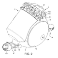
図1は、真空掃除機1の形態をした清掃具の外面図である。真空掃除機1は、典型的には利用の際にホース及びワンドから成る集合体の後方に引っ張られるボディ2を具備するシリンダ型又はキャニスタ型である。図2〜図6は、ボディ2のさらなる詳細図である。
FIG. 1 is an external view of a cleaning tool in the form of a vacuum cleaner 1. The vacuum cleaner 1 is typically of a cylinder type or a canister type having a
ボディ2は、塵埃を空気流から分離するための分離器4を備えている。好ましくは、分離器4は、サイクロン式分離器の形態とされる。分離器4が、分離器4の少なくとも一部分が転動アセンブリ6の内部に組み込まれるか又はドッキングされるように、床接触式転動アセンブリ6の内部に受容されている。分離器4は、転動アセンブリ6から取り外し可能とされるので、分離器4によって収集された如何なる塵埃も取り出すことができる。
The
転動アセンブリ6は、本体8と2つのホイール10,12とを備えている。2つのホイール10,12は、床面と接触させるためのものであり、本体8の側部それぞれに転動可能に接続されている。利用の際には、真空掃除機1は、ホイール10,12の縁部14を介して引っ張られ、ホイール10,12の縁部14を接触させて走行するだろう。
The rolling
転動アセンブリ6の外面及び/又は視認可能な表面の大部分が、丸められているか、湾曲されているか、又は転動アセンブリ6の全体形状が略回転楕円体又は略球体の形状となるように概略的に湾曲されている。このような形状によって、真空掃除機1を利用する際に、真空掃除機1が湾曲した表面を接触させて転動可能となる。このことは、例えば真空掃除機1がその側方又は後方に傾いた場合に生じ得る。図示の実施例では、本体8の湾曲面16が、転動アセンブリ6の後部に向かって配設されている。言い換えれば、真空掃除機1が利用の際に後転した場合であっても、真空掃除機1は湾曲面16を接触させて転動可能とされる。ホイール10,12は、真空掃除機1が利用の際にその側方に傾いた場合に真空掃除機1がホイール10,12それぞれを接触させて転動可能とされるように、転動アセンブリ6の側面それぞれに配設されている。
Most of the outer surface and / or visible surface of the rolling
最も好ましくは、真空掃除機1は、真空掃除機1が利用の際に転動アセンブリ6の湾曲面のうち1つ以上の湾曲面の方に傾いた場合に、真空掃除機1が付勢されることによって図1に表わす直立姿勢に復帰するように構成されている。このことは、真空掃除機1の重心を可能な限り低くすることによって実現される。
Most preferably, the vacuum cleaner 1 is energized when the vacuum cleaner 1 is tilted toward one or more of the curved surfaces of the rolling
図7は、ホイール10,12を取り外した状態における分解図である。図8〜図10は、分離器4を取り外した状態における転動アセンブリ6を表わす。図示の如く、転動アセンブリ6のホイール10,12それぞれが、略半球体の形状とされるか、半球体の一部分を形成している。ホイール10,12は、ドーム状又は略ドーム状の形態とされる。言うまでもなく、ホイール10,12は、段付の外面を有しているか、又は1つ以上の平坦部分を有している一方、略半球体の形状とされ、略球体又は略回転楕円体の形態とされる転動アセンブリ6を本体8と共に形成している。
FIG. 7 is an exploded view with the
図示の如く、転動アセンブリ6の側面20は、ホイール10,12の下方に位置しているので、真空掃除機1の利用の際には隠れているが、側面20がホイール10,12の内面22に向かって突出しているように丸められているか、又は湾曲されている。これにより、真空掃除機1の構成部品を配置させるための本体8の内部空間を最大に確保することができる。言うまでもなく、このような特徴は本質的なものではなく、側面20は、平坦であっても、段付でも、側面20がホイール10,12の内面22の外形に追従しない他の態様で形成されていても良い。
As shown in the drawing, the
これら図面に表わすように、転動アセンブリ6は、真空掃除機1の利用の際に真空掃除機1を転動させることができる略回転楕円体状の外面を有している。また、図示の如く、本体8は、分離器4の少なくとも一部分を収容可能とされる凹所18を有している。凹所18と、例えば本体8に設けられたハンドル24、プラグカラー26、及び平坦なベース面28のような本体8の他の表面形体とが存在することによって、転動アセンブリ6全体が略回転楕円体であるという事実が損なわれる訳ではない。実際に、転動アセンブリ6は、多数の突起、切欠、又は閉端部分を有しているが、略球体又は回転楕円体の形態とみなされ、本発明の技術的意義の範囲内では転動アセンブリ6とみなされる。このことは、転動アセンブリ6の全体的な外観が略球体又は略回転楕円体の形態であるとみなされる限り、当て嵌まる。凹所18を具備するとしても、転動アセンブリ6は、略回転楕円体の形態であるとみなされる。転動アセンブリ6の内部にドッキングされた分離器4を転動アセンブリ6が具備する場合であっても、転動アセンブリ6の全体的な外観が、回転楕円体、球体、又はボールの形態であるからである。
As shown in these drawings, the rolling
ホイール10,12の回転軸線が、ホイール10,12の縁部14が床面に接触するように真空掃除機1が配置されている床面から上方に向かって傾斜している。ホイール10,12の回転軸線の傾斜角度は、好ましくは0°〜15°の範囲、より好ましくは6°〜10°の範囲とされるが、当該実施例では約3°である。代替的な実施例では、ホイールの回転軸線が水平になっている場合がある。
The rotation axes of the
分離器4が転動アセンブリ6の内部に受容された場合には、分離器4の長手方向軸線は、分離器4が垂直軸線から0°〜60°の範囲の角度で配置されるように傾斜している。このような配置は、単に分離器4を上方から転動アセンブリ6の上に降下させることによって、分離器4のドッキングを可能とする。この点においては、分離器4が転動アセンブリ6の内部に受容された場合であっても、転動アセンブリ6は分離器4の上面の周囲に延在していない。図示の如く、分離器4の最後方地点32が、ホイール10,12の中心点34を通過して垂直に延在している直線Lの上に又は当該直線Lの後方に配置されている。好ましくは、分離器4のさらなる構成部品も、直線Lの後方に配置されている。これについては、以下において詳述する。
When the separator 4 is received inside the rolling
図示の如く、分離器4が転動アセンブリ6の内部に受容されている場合には、分離器4の一部分が、視認可能な状態にあると共に、真空掃除機1の外面の一部分を形成している。凹所18の大きさ及び深さは、任意であるが、所望の大きさの分離器4を収容可能な大きさとされる。添付図面に表わす実施例では、分離器4は、凹所18の内部に受容されているので、真空掃除機1を側面から見た場合には、分離器4と転動アセンブリ6との間には視認可能な間隙が存在しない。このような側面図は、図4に最も良く表わされている。図示の実施例では、分離器4は、分離器4の長さの大部分に亘って転動アセンブリ6の内部に受容されている。理想的には、分離器4は、分離器4の長さの少なくとも50%に亘って転動アセンブリ6の内部に受容されている。最も好ましい実施例では、分離器4は、分離器4の長さの少なくとも90%に亘って転動アセンブリ6の内部に受容されている。
As shown, when the separator 4 is received within the rolling
図8、図9、及び図10に表わすように、凹所18は、多数の成形された窪み36を備えている。成形された窪み36は、分離器4の対応して成形された部分を収容するように形成されているので、分離器4は、凹所18の内部に密接に受容される。凹所18及び成形された窪み36の輪郭が、凹所18及び成形された窪み36の内部に受容される分離器4の一部分の外部形状に密接に適応しているからである。成形された窪み36については、以下において詳述する。
As shown in FIGS. 8, 9, and 10, the
図1に表わすように、真空掃除機10は、可撓性を有しているホース38を備えており、ホース38は、ワンド組立体42に接続するためにボディ2と旋回式カップリング40との間に延在している。ワンド組立体42は、塵埃を含む空気流が真空掃除機1の内部に引き込まれる際に通過する吸引開口部46を備えている、掃除機ヘッド44に接続されている。可撓性を有しているホース38は、入口ダクト48と結合している旋回式継手47を介して、ボディ2に接続されている。入口ダクト48は、汚染空気入口ダクト70と接続しており、汚染空気入口ダクト70は、汚染空気を入口ダクト48から分離器4の内部に輸送する。旋回式継手47については、以下において詳述する。掃除機ヘッド44、ホース38、及びワンド組立体42については、明瞭にすることのみを目的として、図1以外の図面からは除外している。
As shown in FIG. 1, the
床面の上において真空掃除機1を操作するために、利用者は、ワンドハンドル49を保持して移動させる。これにより、ワンドハンドル49とホース38、ワンド組立体42、旋回式カップリング40、及び旋回式継手47とが接続されているので、床面の上において真空掃除機1を引きずることができる。従って、これにより、転動アセンブリ6のホイール10,12を回転させ、床面の上において真空掃除機1を移動させることができる。
In order to operate the vacuum cleaner 1 on the floor surface, the user holds and moves the
図11及び図12に表わすように、空気を掃除機ヘッド44から分離器4に引き込むための吸引源50が、分離器4の下方の位置において本体8の内部に取り付けられている。吸引源50が比較的重いので、吸引源50を分離器4の下方に配置することによって、真空掃除機1の重心を比較的低くすることができる。その結果として、真空掃除機1の安定性が改善される。さらに、真空掃除機1の取り扱い及び操作性が一層容易になる。好ましくは、吸引源50及び/又は真空掃除機1の他の構成部品は、利用の際に真空掃除機1が転動アセンブリ6の湾曲面のうち1つ以上の湾曲面の方に傾いた場合に、真空掃除機1が付勢されることによって図1〜図3に表わす直立姿勢に復帰するように配置されている。このことは、ボディ2の重心を低くすることによって実現される。
As shown in FIGS. 11 and 12, a
分離器4については、図11、図12、及び図13を参照しつつ詳述する。分離器4は、サイクロン式分離器である。分離器4は、略円筒状の形態とされる外壁54を有している外側容器52を備えている。外側容器52の下側端部は、外壁54に回動可能に取り付けられたベース56によって閉じられている。ベース56は、外壁54に設けられたリップ60と係合するキャッチ58によって、閉位置において保持されている。閉位置では、ベース56は、外壁54の下側端部に対して密閉されている。キャッチ58は、弾性的に変形可能とされるので、空にするために分離器4が転動アセンブリ6から取り外された場合に、キャッチ58の最も上側の部分に作用する下向きの圧力によって、キャッチ48がリップ60から離隔するように移動され、リップ60から係合解除される。この場合には、ベース56は、外壁54から離隔するように降下する。
The separator 4 will be described in detail with reference to FIGS. 11, 12, and 13. The separator 4 is a cyclone separator. Separator 4 includes an
サイクロン式分離器4の全体形状は、サイクロン式分離器4を利用する真空掃除機1の大きさ及びタイプに従って変更可能とされる。例えば、分離器4の全長は、清掃具の直径に対して大きくしても小さくしても良く、ベース56の形状は、例えば平坦又は略円錐台状になるように変更可能とされる。 The overall shape of the cyclonic separator 4 can be changed according to the size and type of the vacuum cleaner 1 that uses the cyclonic separator 4. For example, the total length of the separator 4 may be made larger or smaller than the diameter of the cleaning tool, and the shape of the base 56 can be changed to be flat or substantially frustoconical, for example.
さらに、分離器4は、第2の円筒状壁62を備えている。第2の円筒状壁62は、外壁54のラジアル方向内方に配置されており、環状のチャンバ64を外壁54と第2の円筒状壁62との間に形成するように、外壁54から離隔されている。第2の円筒状壁62は、(ベース56が閉位置に位置している場合に)ベース56と接触しており、ベース56に対して密閉されている。円筒状チャンバ67の境界は、第2の円筒状壁62、ベース56、及びシャーシ69によって形成されている。環状チャンバ64の境界は、概略的に外壁54、第2の円筒状壁62、ベース56、外側容器52の上側端部に位置する上側壁66、及び環状チャンバ64からの流体出口を形成する馬蹄状のシュラウド68によって形成されている。
In addition, the separator 4 includes a second
汚染空気入口ダクト70は、汚染空気を入口ダクト48から外側容器52の上側端部に運搬するために円筒状チャンバ67を貫通している通路を備えており、掃除機ヘッド44からの汚染空気流をホース38及びワンド組立体42を介して受容する。
The contaminated
入口ダクト48の端部72は、環状チャンバ64と流通している。当該実施例では、入口ダクト48の端部72は、シュラウド68に取り付けられている壁部分74に形成されている。入口ダクト48の端部72は、流入する汚染空気を環状チャンバ64の周囲の螺旋状経路に強制的に追従させるように、外側容器52に対して接線方向に配置されている。従って、環状チャンバ64は、分離効率が低いサイクロンとして機能する。
An
上述のように、シュラウド68は、環状チャンバ64のための流体出口として機能する。シュラウド68は、馬蹄状に成形された壁76と、馬蹄状に成形された壁76から垂下しているスカート部分78とを有している。また、スカート部分78は、シュラウド68に取り付けられている壁部分74から垂下している。スカート部分78は、外壁54に向かって外方に拡幅している。多数の穿孔80が、シュラウド68に形成されている。単一の環状チャンバ64からの唯一の流体出口が、シュラウド68の穿孔80によって形成されている。通路82は、シュラウド68と第2の円筒状壁62との間に形成されている。通路82は、プレナムチャンバ85を介して、複数の第2の段のサイクロン84と連通している。
As described above, the
第2の段のサイクロン84は、二層で、すなわち第1の層86と第1の層86の上方に配置されている第2の層88とに配置されている。第2の段のサイクロン84は、第2の段のサイクロン84を通過する空気流が並走するように配置されている。第1の層86及び第2の層88それぞれの第2の段のサイクロン84は、プレナムチャンバ85の周囲において周方向に沿って配置されている。第2の段のサイクロン84それぞれは、プレナムチャンバ85と連通している接線方向の入口90を有している。第2の段のサイクロン84それぞれが、他の第2の段のサイクロン84と同一とされ、円筒状の上側部分92と、上側部分92から垂下しているテーパ状部分94とを備えている。第2の段のサイクロン84それぞれのテーパ状部分94は、円錐台状の形態とされ、錐状の開口部96で終端している。第2の段のサイクロン84は、第2の円筒状壁62によって境界が形成されている円筒状チャンバ67の内部に延在しており、円筒状チャンバ67と流通している。円筒状チャンバ67は、第2の段のサイクロン84によって分離された塵埃のための塵埃収集器として機能する。渦ファインダ98が、空気を第2の段のサイクロン84から排出するために、第2の段のサイクロン84それぞれの上側部分に設けられている。渦ファインダ98それぞれが、分離器4の側面に配置された清浄空気出口102を形成するために、第2の段のサイクロン84同士の間を延在している出口ダクト100と連通している。分離器4が転動アセンブリ6にドッキングされた場合には、清浄空気出口102は、視認不可能となり、吸引源入口ダクト104と接続する。
The
好ましい実施例では、28個の第2の段のサイクロン84が、14個の第2の段のサイクロン84ずつ第1の層86及び第2の層88に配置されている。14個の第2の段のサイクロン84から成るセットそれぞれが、外側容器52の長手方向軸線XIを中心として環状に配置されている。第2の段のサイクロン84それぞれは、長手方向軸線XIに向かって下方に傾斜している軸線Cを有している。すべての軸線Cが、同一の角度で長手方向軸線XIに対して傾斜している。しかしながら、代替的には、第1の層86の第2の段のサイクロン84は、第2の層88の第2の段のサイクロン84とは異なる角度で長手方向軸線XIに対して傾斜している。環状チャンバ64が、分離効率が低い第1のサイクロン式分離ユニットを形成している一方、第2の段のサイクロン84は、第2のサイクロン式分離ユニットを形成していると考えることができる。
In the preferred embodiment, twenty-eight second-
第2のサイクロン式分離ユニットでは、第2の段のサイクロン84それぞれの直径が、環状チャンバ64の直径より小さいので、第2のサイクロン式分離ユニットが分離可能とされる塵埃粒子は、第1のサイクロン式分離ユニットが分離可能とされる塵埃粒子より小さい。第2のサイクロン式分離ユニットのさらなる利点は、第1のサイクロン式分離ユニットによって既に清浄された空気を利用することであるので、当該清浄された空気中に含まれる粒子の量及び平均的な大きさは、清浄されていない空気中に含まれる粒子の量及び平均的な大きさより小さい。第2のサイクロン式分離ユニットの分離効率は、第1のサイクロン式分離ユニットの分離効率より高い。
In the second cyclonic separation unit, since the diameter of each of the
上述のように、転動アセンブリ6の本体8は、モータ駆動されるファンユニットの形態とされる吸引源50を備えている。また、本体8は、ファンユニット50のモータに給電する電線の一部分を本体8の内部に収納及び保管するためのケーブル巻取組立体106を備えている。ファンユニット50は、モータと、塵埃を含む空気流を真空掃除機1の内部に吸い込むとと共に真空掃除機1と通過させるために当該モータによって駆動される羽根車とを備えている。ファンユニット50は、モータバケット108に収容されている。モータバケット108は、真空掃除機1を床面上で操作する際にファンユニット50が回転しないように、本体8に接続されている。後方モータフィルタ組立体110は、本体8の内部に並びに吸引源50の周囲及び上方に配置されている。後方モータフィルタ組立体110は、転動アセンブリ6の内部空間のうち大部分を形成しているモータバケット108を後方モータフィルタ組立体110が囲むことができるように、馬蹄状の形態とされる。後方モータフィルタ組立体110によって囲まれているモータバケット108の一部分には、複数の穿孔が形成されている。シール112は、ケーブル巻取組立体106をモータバケット108から隔離している。
As described above, the
さらに、本体8は、清浄された空気を真空掃除機1から排出するための空気排出ポート114を備えている。このことは、図7に最も良く表わされている。空気排出ポート114は、本体8の側面20に形成されているので、ホイール10,12が所定の位置に配置されている場合には、空気排出ポート114が視認することができないが、排出された空気は本体8の側面20とホイール10,12の内面22との間から排気される。好ましい実施例では、空気排出ポート114は、多数の出口穴116を備えている。代替的な実施例では、空気排出ポート114は、本体8の他の部分に配設されている。図10では、空気排出ポート114は、本体8の外面30に配設されている。
Further, the
利用時には、ファンユニット50は、利用者を介して、例えば転動アセンブリ6の本体8の上面に配置されたボタン118を押すことによって起動される。これにより、塵埃を含む空気流が、掃除機ヘッド44の吸引開口部46を通じて真空掃除機1の内部に引き込まれる。塵埃を含む空気は、ホース38及びワンド組立体42を通過し、旋回式継手47を介して入口ダクト48に流入する。その後に、塵埃を含む空気は、分離器4の汚染空気入口ダクト70に流入する。汚染空気入口ダクト70の端部72が接線方向に配置されていることに起因して、空気流は、外壁54に関する螺旋状経路に追従する。より大きい塵埃粒子が、サイクロン作用によって環状チャンバ64内に堆積し収集される。
In use, the
部分的に清浄された空気流は、シュラウド68の穿孔80を介して環状チャンバ64から流出し、通路82に流入する。その後に、空気流は、プレナムチャンバ85に流入し、第2の段のサイクロン84の入口90を介して、プレナムチャンバ85から第2の段のサイクロン84の内部に流入する。第2の段のサイクロン84では、さらなるサイクロン方式による分離によって、依然として空気流中に含まれている塵埃が取り除かれる。取り除かれた塵埃が、円筒状チャンバ67内に堆積する一方、清浄された空気は、渦ファインダ98を介して第2の段のサイクロン84から流出し、出口ダクト100に流入する。その後に、空気流は、吸引源入口ダクト104を通じて転動アセンブリ6の本体8に流入する。
The partially cleaned air stream exits the
入口ダクト104は、空気流をファンユニット50の内部に案内する。空気流は、モータ排出ダクトからモータバケット108に流入する。その後に、空気流は、モータバケット108から流出し、後方モータフィルタ組立体110を通過する。最後に、空気流は、空気排出ポート114の出口穴116に至るまで本体8の曲面に追従する。清浄された空気流は、空気排出ポート114の出口穴116を通じて、真空掃除機1から排出される。
The
分離器4は、分離器4を真空掃除機1から容易に取り外すためのハンドル24を備えている。空にするために分離器4を真空掃除機1から取り外し可能とするために、利用者は、キャッチ解放ボタン120を押下することによって、ハンドル24を本体8のハンドルキャッチ122から解放させることができる。ハンドルキャッチ122は、一般的な利用の際には、分離器4を本体8に取り付けられた状態に維持している。任意のハンドルキャッチ及びキャッチ解放ボタンであっても、適切であれば利用可能とされる。
The separator 4 includes a
収集された塵埃を分離器4から排出可能とするために、利用者は、分離器4を真空掃除機1から取り外すことができる。ハンドル24を介して分離器4を保持している際に、利用者がキャッチ解放ボタン120を押下することによって、ロッドがキャッチ58を押圧する。キャッチ58に作用する下向きの圧力が、外側容器52の外壁54においてキャッチ58をリップ60から離隔するように移動させるので、ベース56が、外壁54から離隔するように落下し、これにより、分離器4の内部に収集された塵埃が分離器4から取り除かれる。
In order to allow the collected dust to be discharged from the separator 4, the user can remove the separator 4 from the vacuum cleaner 1. While holding the separator 4 via the
可撓性を有しているホース38は、旋回式継手47のコネクタ126と密閉状態で係合しているホースカフス124を備えている。コネクタ126は、回転式コネクタであって、入口ダクト48の少なくとも第1の部分128に対して平行とされる軸線X2を中心として密閉状態で回転するように配置されている。このような回転を可能とするために、コネクタ126は、第1の部分128を中心として、又は入口ダクト48の起点に固定されている第1の部分カフス130を中心として回転可能とされる。利用の際に、利用者がホース38及びワンド組立体42を特定の方向に引っ張ると、このような配置に起因して、旋回式継手47が、入口ダクト48を中心としてコネクタ126を旋回させるので、真空掃除機の安定性が、継手が固定されている場合と比較して確実に高くなる。
The
上述のように、図8〜図10に表わすように、凹所18が多数の成形された窪み36を備えている。成形された窪み36が、対応して成形された第2の段のサイクロン84を収容するように形成されているので、分離器4が転動アセンブリ6上に載置された場合に視認することができない第2の段のサイクロン84それぞれは、第2のサイクロン84の外部形状に密接に適応している成形された窪み36の内部に受容される。従って、図示の実施例では、2列に配置された成形された窪み36は、第2の段のサイクロン84から成る第1の層86及び第2の層88に対応している。
As described above, as shown in FIGS. 8 to 10, the
図14及び図15に表わすように、分離器4が転動アセンブリ6の凹所18の内部に受容又はドッキングされた場合に視認不可能となる分離器4の割合は異なる。図14に表わすように、真空掃除機1を側方から見た場合に、凹所18の最大深さ(P)の地点において、分離効率が低いサイクロン(環状チャンバ64)の幅の少なくとも5分の1が、転動アセンブリ6の一部分によって隠されている。図15では、視認することができない分離効率が低いサイクロンの割合が一層大きく、この場合には5分の4を越えている。図4に表わす好ましい実施例では、凹所18の最大深さ(P)の地点において、分離効率が低いサイクロン(環状チャンバ64)の幅の少なくとも2分の1が、転動アセンブリ6の一部分によって隠されている。
As shown in FIGS. 14 and 15, the proportion of the separator 4 that is not visible when the separator 4 is received or docked inside the
上述のように、分離器4の最後方地点32は、ホイール10,12の中心点34を通過する垂直線Lの上に又は当該垂直線Lの後方に配置されている。一般に、ハンドル24は、当該特徴に関して分離器の一部分とは考えられていない。図4及び図15に表わす好ましい実施例では、分離効率が低いサイクロンの(分離器4が転動アセンブリ6の内部に受容された場合における)最後方の可視地点131は、垂直線Lの上に又は当該垂直線Lの後方に配置されている。言い換えれば、最後方の可視地点131は、分離効率が低いサイクロンの外壁54が転動アセンブリ6を分断している場合に外壁54の頂部が第2の段のサイクロン84に接続している地点とされる。好ましくは、第2のサイクロン段の頂縁部132が、本体8の湾曲面16と一致している。このことは、図4及び図15に表わされている。
As described above, the
また、本体8は、第2のハンドル134を備えており、第2のハンドル134は、分離器4が転動アセンブリ6の内部に受容された場合に滑らかに湾曲した表面を形成するように、ハンドル24と一致している。また、この第2のハンドル134は、第2のハンドル134が転動アセンブリ6の転動を妨げないように湾曲している。すなわち、分離器4が後方に傾いた場合に、分離器4は、立ち往生せずに自立することができるように湾曲している。
The
本発明は、上述の発明の詳細な説明に限定される訳ではない。当業者であれば、変形例を想到することができるからである。 The present invention is not limited to the above detailed description of the invention. This is because those skilled in the art can conceive modifications.
1 真空掃除機
2 (真空掃除機1の)ボディ
4 分離器
6 転動アセンブリ
8 (転動アセンブリ6の)本体
10 ホイール
12 ホイール
14 (ホイール10,12の)縁部
16 (本体8の)湾曲面
18 凹所
20 (転動アセンブリ6の)側面
22 (ホイール10,12の)内面
24 ハンドル
26 プラグカラー
28 ベース面
30 (本体8の)外面
32 (分離器4の)最後方地点
34 (ホイール10,12の)中心点
36 成形された窪み
38 ホース
40 旋回式カップリング
42 ワンド組立体
44 掃除機ヘッド
46 吸引開口部
47 旋回式継手
48 入口ダクト
49 ワンドハンドル
50 吸引源
52 外側容器
54 (外側容器52の)外壁(第1の円筒状壁)
56 ベース
58 キャッチ
60 リップ
62 第2の円筒状壁
64 環状チャンバ
66 上側壁
67 円筒状チャンバ
68 シュラウド
69 シャーシ
70 汚染空気入口ダクト
72 (入口ダクト48の)端部
74 壁部分
76 馬蹄状に成形された壁
78 スカート部分
80 穿孔
82 通路
84 第2の段のサイクロン
85 プレナムチャンバ
86 第1の層
88 第2の層
90 入口
92 円筒状の上側部分
94 テーパ状部分
96 錐状の開口部
98 渦ファインダ
100 出口ダクト
102 清浄空気出口
104 吸引源入口ダクト
106 ケーブル巻取組立体
108 モータ
110 後方モータフィルタ組立体
112 シール
114 空気排出ポート
116 出口穴
120 キャッチ解放ボタン
124 ホースカフス
126 コネクタ
128 第1の部分
130 第1の部分カフス
131 最後方の可視点
132 (第2のサイクロン段の)頂縁部
134 第2のハンドル
DESCRIPTION OF SYMBOLS 1
56
Claims (12)
前記分離器を受容するための凹所を有している本体と、前記本体に回転可能に接続されている複数の床接触式ホイールとを備えている床接触式転動アセンブリと、
を備えているシリンダ型清掃具において、
前記凹所が、1つ以上の成形された窪みを備えており、
前記成形された窪みが、前記分離器の対応して成形された部分を収容するように形成されており、これにより前記分離器が、前記凹所の内部に密接した状態で固定され、
前記分離器の一部分が、1つ以上の第2サイクロンの一部分とされ、少なくとも1つの前記第2のサイクロンが、前記分離器が前記凹所に受容されている場合に前記成形された窪みの中に少なくとも部分的に配置されていることを特徴とするシリンダ型清掃具。 A separator for separating the dust from a fluid stream containing the dust, and a first cyclonic separating unit, with which a plurality of second cyclones, at least a portion of the outer surface of the separator formed Said separator having a second cyclonic separation unit,
A floor contact rolling assembly comprising a body having a recess for receiving the separator and a plurality of floor contact wheels rotatably connected to the body;
In the cylinder-type cleaning tool provided with
The recess comprises one or more molded indentations;
The shaped recess is formed to accommodate a correspondingly shaped portion of the separator, whereby the separator is fixed in close contact with the interior of the recess;
A portion of the separator is part of one or more second cyclones, and at least one of the second cyclones is in the shaped recess when the separator is received in the recess. A cylinder-type cleaning tool that is at least partially disposed on the cylinder.
Applications Claiming Priority (3)
| Application Number | Priority Date | Filing Date | Title |
|---|---|---|---|
| GB1210938.5A GB2503253B (en) | 2012-06-20 | 2012-06-20 | A cleaning appliance |
| GB1210938.5 | 2012-06-20 | ||
| PCT/GB2013/051616 WO2013190307A1 (en) | 2012-06-20 | 2013-06-20 | A cleaning appliance |
Publications (3)
| Publication Number | Publication Date |
|---|---|
| JP2015519981A JP2015519981A (en) | 2015-07-16 |
| JP2015519981A5 JP2015519981A5 (en) | 2015-08-27 |
| JP5914756B2 true JP5914756B2 (en) | 2016-05-11 |
Family
ID=46641225
Family Applications (1)
| Application Number | Title | Priority Date | Filing Date |
|---|---|---|---|
| JP2015517854A Active JP5914756B2 (en) | 2012-06-20 | 2013-06-20 | Cleaning tool |
Country Status (6)
| Country | Link |
|---|---|
| US (1) | US9392917B2 (en) |
| EP (1) | EP2863789A1 (en) |
| JP (1) | JP5914756B2 (en) |
| CN (1) | CN104540435B (en) |
| GB (1) | GB2503253B (en) |
| WO (1) | WO2013190307A1 (en) |
Families Citing this family (11)
| Publication number | Priority date | Publication date | Assignee | Title |
|---|---|---|---|---|
| GB2503255B (en) | 2012-06-20 | 2014-10-15 | Dyson Technology Ltd | A cleaning appliance |
| GB2503254B (en) | 2012-06-20 | 2014-12-17 | Dyson Technology Ltd | A cleaning appliance |
| GB2503251C (en) | 2012-06-20 | 2015-07-15 | Dyson Technology Ltd | A self righting cleaning appliance |
| GB2503252B (en) | 2012-06-20 | 2014-12-17 | Dyson Technology Ltd | A self righting cleaning appliance |
| US9885196B2 (en) | 2015-01-26 | 2018-02-06 | Hayward Industries, Inc. | Pool cleaner power coupling |
| EP3250327B1 (en) | 2015-01-26 | 2022-09-28 | Hayward Industries, Inc. | Swimming pool cleaner with hydrocyclonic particle separator and/or six-roller drive system |
| KR102467328B1 (en) * | 2016-02-05 | 2022-11-16 | 삼성전자주식회사 | Cleaner |
| US9896858B1 (en) | 2017-05-11 | 2018-02-20 | Hayward Industries, Inc. | Hydrocyclonic pool cleaner |
| US10156083B2 (en) | 2017-05-11 | 2018-12-18 | Hayward Industries, Inc. | Pool cleaner power coupling |
| US9885194B1 (en) | 2017-05-11 | 2018-02-06 | Hayward Industries, Inc. | Pool cleaner impeller subassembly |
| GB2569818B (en) | 2017-12-30 | 2020-04-15 | Dyson Technology Ltd | A dirt separator |
Family Cites Families (48)
| Publication number | Priority date | Publication date | Assignee | Title |
|---|---|---|---|---|
| US1856133A (en) | 1925-05-07 | 1932-05-03 | Apex Electrical Mfg Co | Suction cleaner |
| GB645847A (en) | 1946-10-10 | 1950-11-08 | Edgar Peter Senne | Improvements in or relating to vacuum cleaners |
| US2621756A (en) | 1948-02-18 | 1952-12-16 | Electrolux Corp | Filter replacement mechanism for vacuum cleaners |
| US2686330A (en) | 1953-01-02 | 1954-08-17 | Ind Patent Corp | Ball-roll vacuum cleaner |
| FR1310618A (en) | 1961-10-17 | 1962-11-30 | Vacuum | |
| JPH0595859A (en) * | 1991-10-11 | 1993-04-20 | Hitachi Ltd | Vacuum cleaner |
| TW471954B (en) * | 2000-03-01 | 2002-01-11 | Matsushita Electric Ind Co Ltd | Electric cleaner |
| JP2001314356A (en) * | 2000-03-01 | 2001-11-13 | Matsushita Electric Ind Co Ltd | Electric vacuum cleaner |
| JP2003093280A (en) * | 2001-09-26 | 2003-04-02 | Matsushita Electric Ind Co Ltd | Vacuum cleaner |
| GB0203150D0 (en) | 2002-02-11 | 2002-03-27 | Dyson Ltd | A filter housing |
| GB2393110A (en) | 2002-09-14 | 2004-03-24 | Dyson Ltd | A cleaning appliance and hose storage means therefor |
| GB2402045B (en) | 2003-05-22 | 2007-01-31 | Dyson Ltd | A cleaning appliance |
| KR100555321B1 (en) | 2005-04-13 | 2006-03-03 | 삼성광주전자 주식회사 | Vacuum cleaner having cyclone dust-separating apparatus |
| KR100577280B1 (en) | 2005-01-04 | 2006-05-10 | 엘지전자 주식회사 | Vacuum cleaner |
| KR100577278B1 (en) | 2005-05-21 | 2006-05-10 | 엘지전자 주식회사 | Vacuum cleaner |
| KR100648960B1 (en) | 2005-10-28 | 2006-11-27 | 삼성광주전자 주식회사 | A multi cyclone separating apparatus |
| KR100648961B1 (en) * | 2005-10-28 | 2006-11-27 | 삼성광주전자 주식회사 | Vacuum cleaner |
| US8012250B2 (en) | 2005-12-10 | 2011-09-06 | Lg Electronics Inc. | Vacuum cleaner |
| US7882592B2 (en) | 2005-12-10 | 2011-02-08 | Lg Electronics Inc. | Vacuum cleaner |
| KR101250077B1 (en) | 2006-04-04 | 2013-04-02 | 엘지전자 주식회사 | Dust collecting unit of vacuum cleaner |
| EP2064981A4 (en) | 2006-09-21 | 2013-09-04 | Suzhou Kingclean Floorcare Co | A dust collector |
| EP1949842B1 (en) | 2007-01-24 | 2015-03-04 | LG Electronics Inc. | Vacuum cleaner |
| KR100776402B1 (en) | 2007-02-05 | 2007-11-16 | 삼성광주전자 주식회사 | Multi cyclone separating apparatus having filter assembly |
| WO2008117945A1 (en) | 2007-03-28 | 2008-10-02 | Chong, Chung-Ook | Vacuum cleaner |
| GB2454227B (en) | 2007-11-01 | 2012-02-29 | Dyson Technology Ltd | Cyclonic separating apparatus |
| KR100996531B1 (en) | 2008-07-02 | 2010-11-24 | 엘지전자 주식회사 | Vacuum cleaner |
| KR101542185B1 (en) | 2008-12-29 | 2015-08-07 | 삼성전자주식회사 | Vacuum cleaner having detachable dust-separating dpparatus |
| GB2468151A (en) * | 2009-02-27 | 2010-09-01 | Dyson Technology Ltd | A surface-treating appliance |
| GB2468150B (en) | 2009-02-27 | 2012-10-03 | Dyson Technology Ltd | Cyclonic separating apparatus |
| US9265395B2 (en) | 2010-03-12 | 2016-02-23 | Omachron Intellectual Property Inc. | Surface cleaning apparatus |
| GB2469046B (en) | 2009-03-31 | 2012-07-25 | Dyson Technology Ltd | Mounting arrangement for separating apparatus in a cleaning appliance |
| GB2469049B (en) | 2009-03-31 | 2013-04-17 | Dyson Technology Ltd | A cleaning appliance with steering mechanism |
| EP2413764B1 (en) * | 2009-03-31 | 2015-07-22 | Dyson Technology Limited | A cleaning appliance |
| GB2475312B (en) * | 2009-11-16 | 2014-01-08 | Dyson Technology Ltd | A surface treating appliance |
| GB2475313B (en) * | 2009-11-16 | 2014-01-08 | Dyson Technology Ltd | A surface treating appliance |
| JP4947161B2 (en) * | 2010-02-04 | 2012-06-06 | 三菱電機株式会社 | Cyclone separation device and vacuum cleaner |
| JP5477392B2 (en) | 2010-02-05 | 2014-04-23 | 三菱電機株式会社 | Electric vacuum cleaner |
| CN102905596B (en) | 2010-05-31 | 2015-09-30 | 三菱电机株式会社 | Electric vacuum cleaner |
| GB2484122A (en) | 2010-09-30 | 2012-04-04 | Dyson Technology Ltd | A cylinder type cleaning appliance |
| GB2484120B (en) * | 2010-09-30 | 2014-10-01 | Dyson Technology Ltd | A cleaning appliance |
| JP4900520B1 (en) * | 2011-03-31 | 2012-03-21 | 三菱電機株式会社 | Vacuum cleaner |
| EP2564750B1 (en) * | 2011-09-02 | 2018-11-21 | Samsung Electronics Co., Ltd. | Vacuum cleaner having a dust separating apparatus |
| JP2015507980A (en) * | 2012-02-22 | 2015-03-16 | アクティエボラゲット エレクトロラックス | Vacuum cleaner filter assembly and vacuum cleaner |
| JP5905748B2 (en) | 2012-03-06 | 2016-04-20 | 三菱電機株式会社 | Cyclone separation device and vacuum cleaner |
| GB2503251C (en) | 2012-06-20 | 2015-07-15 | Dyson Technology Ltd | A self righting cleaning appliance |
| GB2503254B (en) | 2012-06-20 | 2014-12-17 | Dyson Technology Ltd | A cleaning appliance |
| GB2503252B (en) | 2012-06-20 | 2014-12-17 | Dyson Technology Ltd | A self righting cleaning appliance |
| KR101414656B1 (en) * | 2012-08-31 | 2014-07-03 | 엘지전자 주식회사 | vacuum cleaner |
-
2012
- 2012-06-20 GB GB1210938.5A patent/GB2503253B/en not_active Expired - Fee Related
-
2013
- 2013-06-20 CN CN201380042427.1A patent/CN104540435B/en not_active Expired - Fee Related
- 2013-06-20 WO PCT/GB2013/051616 patent/WO2013190307A1/en active Application Filing
- 2013-06-20 JP JP2015517854A patent/JP5914756B2/en active Active
- 2013-06-20 US US14/409,884 patent/US9392917B2/en not_active Expired - Fee Related
- 2013-06-20 EP EP13731459.7A patent/EP2863789A1/en not_active Ceased
Also Published As
| Publication number | Publication date |
|---|---|
| EP2863789A1 (en) | 2015-04-29 |
| CN104540435A (en) | 2015-04-22 |
| CN104540435B (en) | 2016-04-13 |
| GB201210938D0 (en) | 2012-08-01 |
| GB2503253A (en) | 2013-12-25 |
| GB2503253B (en) | 2014-10-15 |
| US9392917B2 (en) | 2016-07-19 |
| WO2013190307A1 (en) | 2013-12-27 |
| JP2015519981A (en) | 2015-07-16 |
| US20150320273A1 (en) | 2015-11-12 |
Similar Documents
| Publication | Publication Date | Title |
|---|---|---|
| JP5869729B2 (en) | Free-standing cleaning tool | |
| JP5869730B2 (en) | Cleaning tool | |
| JP5869732B2 (en) | Cleaning tool | |
| JP5914756B2 (en) | Cleaning tool | |
| JP5869731B2 (en) | Cleaning appliances | |
| JP5869728B2 (en) | Self-erection cleaning household appliances |
Legal Events
| Date | Code | Title | Description |
|---|---|---|---|
| A521 | Written amendment |
Free format text: JAPANESE INTERMEDIATE CODE: A523 Effective date: 20150217 |
|
| A621 | Written request for application examination |
Free format text: JAPANESE INTERMEDIATE CODE: A621 Effective date: 20150217 |
|
| A521 | Written amendment |
Free format text: JAPANESE INTERMEDIATE CODE: A523 Effective date: 20150605 |
|
| A871 | Explanation of circumstances concerning accelerated examination |
Free format text: JAPANESE INTERMEDIATE CODE: A871 Effective date: 20150605 |
|
| A975 | Report on accelerated examination |
Free format text: JAPANESE INTERMEDIATE CODE: A971005 Effective date: 20150612 |
|
| A131 | Notification of reasons for refusal |
Free format text: JAPANESE INTERMEDIATE CODE: A131 Effective date: 20150810 |
|
| A601 | Written request for extension of time |
Free format text: JAPANESE INTERMEDIATE CODE: A601 Effective date: 20151015 |
|
| A521 | Written amendment |
Free format text: JAPANESE INTERMEDIATE CODE: A523 Effective date: 20160127 |
|
| TRDD | Decision of grant or rejection written | ||
| A01 | Written decision to grant a patent or to grant a registration (utility model) |
Free format text: JAPANESE INTERMEDIATE CODE: A01 Effective date: 20160314 |
|
| A61 | First payment of annual fees (during grant procedure) |
Free format text: JAPANESE INTERMEDIATE CODE: A61 Effective date: 20160404 |
|
| R150 | Certificate of patent or registration of utility model |
Ref document number: 5914756 Country of ref document: JP Free format text: JAPANESE INTERMEDIATE CODE: R150 |
|
| R250 | Receipt of annual fees |
Free format text: JAPANESE INTERMEDIATE CODE: R250 |