JP5905748B2 - Cyclone separation device and vacuum cleaner - Google Patents

Cyclone separation device and vacuum cleaner Download PDF

Info

Publication number
JP5905748B2
JP5905748B2 JP2012049465A JP2012049465A JP5905748B2 JP 5905748 B2 JP5905748 B2 JP 5905748B2 JP 2012049465 A JP2012049465 A JP 2012049465A JP 2012049465 A JP2012049465 A JP 2012049465A JP 5905748 B2 JP5905748 B2 JP 5905748B2
Authority
JP
Japan
Prior art keywords
dust
primary
swirl chamber
cyclone
cyclone separator
Prior art date
Legal status (The legal status is an assumption and is not a legal conclusion. Google has not performed a legal analysis and makes no representation as to the accuracy of the status listed.)
Active
Application number
JP2012049465A
Other languages
Japanese (ja)
Other versions
JP2012106087A5 (en
JP2012106087A (en
Inventor
草太 小前
草太 小前
前田 剛志
剛志 前田
星崎 潤一郎
潤一郎 星崎
小林 朋生
朋生 小林
岩原 明弘
明弘 岩原
飯塚 政義
政義 飯塚
福島 忠史
忠史 福島
健児 柳沢
健児 柳沢
近藤 大介
大介 近藤
Current Assignee (The listed assignees may be inaccurate. Google has not performed a legal analysis and makes no representation or warranty as to the accuracy of the list.)
Mitsubishi Electric Home Appliance Co Ltd
Mitsubishi Electric Corp
Original Assignee
Mitsubishi Electric Home Appliance Co Ltd
Mitsubishi Electric Corp
Priority date (The priority date is an assumption and is not a legal conclusion. Google has not performed a legal analysis and makes no representation as to the accuracy of the date listed.)
Filing date
Publication date
Application filed by Mitsubishi Electric Home Appliance Co Ltd, Mitsubishi Electric Corp filed Critical Mitsubishi Electric Home Appliance Co Ltd
Priority to JP2012049465A priority Critical patent/JP5905748B2/en
Publication of JP2012106087A publication Critical patent/JP2012106087A/en
Publication of JP2012106087A5 publication Critical patent/JP2012106087A5/ja
Application granted granted Critical
Publication of JP5905748B2 publication Critical patent/JP5905748B2/en
Active legal-status Critical Current
Anticipated expiration legal-status Critical

Links

Images

Description

本発明は、機外から吸引した含塵空気(塵埃を含んだ空気)を旋回させることで、空気と塵埃を遠心分離して捕集するサイクロン分離装置並びにこのサイクロン分離装置を備えた電気掃除機に関するものである。   The present invention relates to a cyclone separating device that centrifugally collects air and dust by swirling dust-containing air (air containing dust) sucked from outside the machine, and a vacuum cleaner equipped with the cyclone separating device It is about.

従来のサイクロン分離装置、特に電気掃除機などに用いるサイクロン分離装置は、電動送風機によって吸引された含塵空気を、集塵フィルターや集塵袋を通過させることによって、空気中の塵埃を回収する構造となっていた。しかし、このようなサイクロン分離装置を用いた電気掃除機では、定期的に集塵袋を購入して電気掃除機本体内に取り付ける必要があり、使用者にとって煩雑であり負担が多いという問題があった。   Conventional cyclone separators, especially cyclone separators used in vacuum cleaners, etc., have a structure that collects dust in the air by passing the dust-containing air sucked by the electric blower through the dust collection filter and dust collection bag It was. However, in a vacuum cleaner using such a cyclone separator, it is necessary to periodically purchase a dust bag and install it in the main body of the vacuum cleaner, which is cumbersome and burdensome for the user. It was.

このような問題に対し、消耗品の集塵袋を使用せずに、遠心力や慣性力を利用して空気と塵埃を分離し、塵埃を捕集することが可能なサイクロン分離装置を搭載した電気掃除機が提案されている。このようなサイクロン分離装置を搭載した電気掃除機として、例えば、同心円状に設けられた、外サイクロンと外サイクロンに内包される内サイクロンを、直列に連通させて設けることにより、サイクロン分離装置による塵埃の分離性能を高効率化させた電気掃除機が提案されている(たとえば、特許文献1〜3参照)。   For such problems, a cyclone separator that can collect dust by separating air and dust using centrifugal force and inertial force without using a consumable dust bag is installed. A vacuum cleaner has been proposed. As a vacuum cleaner equipped with such a cyclone separator, for example, by providing a concentric outer cyclone and an inner cyclone contained in the outer cyclone in series, the dust generated by the cyclone separator can be reduced. There has been proposed a vacuum cleaner in which the separation performance of the vacuum cleaner is improved (see, for example, Patent Documents 1 to 3).

特公昭62−50141号公報Japanese Examined Patent Publication No. 62-50141 特表2008−541815号公報Special table 2008-541815 特表2008−541816号公報Japanese translation of PCT publication No. 2008-541816

上記の特許文献1〜3に記載の従来のサイクロン分離装置によれば、複数の旋回室を直列に接続することにより、サイクロン分離装置の塵埃の分離性能を高効率化することができる。しかしながら、これらのサイクロン分離装置は、旋回室である内サイクロンと外サイクロンを同心円状に設けており、つまり旋回室(内サイクロン)をもう1つ旋回室(外サイクロン)で覆っているということであり、内サイクロンの旋回流によって旋回する塵埃が内壁面を擦る音と、外サイクロンの旋回流によって旋回する塵埃が内壁面を擦る音の両方発生し、騒音対策が全くされていなかったという問題点がある。   According to the conventional cyclone separator described in Patent Documents 1 to 3, the dust separation performance of the cyclone separator can be increased by connecting a plurality of swirl chambers in series. However, these cyclone separators are provided with concentric circular inner and outer cyclones which are swirl chambers, that is, the swirl chamber (inner cyclone) is covered with another swirl chamber (outer cyclone). Yes, both the sound of dust swirling by the swirling flow of the inner cyclone and the sound of rubbing dust swirling the inner wall by the swirling flow of the outer cyclone occurred, and no noise countermeasures were taken. There is.

本発明は、上述するような課題を解決するためになされたものであり、含塵空気から塵埃を効率良く分離しつつ、低騒音なサイクロン分離装置並びにそのサイクロン分離装置を備えた電気掃除機を提供することを目的としている。   The present invention has been made to solve the above-described problems, and provides a low-noise cyclone separator and a vacuum cleaner including the cyclone separator while efficiently separating dust from dust-containing air. It is intended to provide.

本発明によるサイクロン分離装置は、外部から吸引した含塵空気が流れ込む流入口と、前記流入口から吸い込まれた含塵空気を旋回させることで前記含塵空気から塵埃を分離する第一の旋回室および第二の旋回室と、第一の開口部から、前記第一の旋回室によって流入した塵埃を捕集する第一の集塵部と、前記第二の旋回室の下方において下向きに設けられた第二の開口部から、前記第二の旋回室によって分離された塵挨を捕集する第二の集塵部と、前記第一の旋回室および前記第二の旋回室によって少なくとも一部の塵埃が分離された空気を排出する排出口を有するサイクロン部を備え、前記サイクロン部に搭載される前記第一の集塵部および前記第二の集塵部は、一体で形成されたダストケースが複数に分割されたうちの二つであり、分割された各々の集塵部は異なる気流流入量で塵埃を捕集し、前記第一の旋回室および前記第二の旋回室の中央軸に垂直な断面において接し、少なくとも前記第一の集塵部および前記第二の集塵部の何れかは角部を有し、前記第一の集塵部が前記第二の集塵部の少なくとも一部を覆うものである。


The cyclone separator according to the present invention includes an inlet into which dust-containing air sucked from outside flows, and a first swirl chamber that separates dust from the dust-containing air by swirling the dust-containing air sucked from the inlet. And a second swirl chamber, a first dust collecting portion for collecting dust flowing in from the first swirl chamber through the first opening, and a lower portion below the second swirl chamber. A second dust collecting portion for collecting dust separated by the second swirl chamber from the second opening, and at least a part of the first swirl chamber and the second swirl chamber . A cyclone unit having a discharge port for discharging air from which dust has been separated is provided, and the first dust collecting unit and the second dust collecting unit mounted on the cyclone unit are integrally formed with a dust case. a two of which are divided into a plurality of minute Are each dust collecting portions are collected dust in different stream inflow, the first swirl chamber and comes in contact with a cross-section perpendicular to the central axis of the second swirl chamber, at least the first dust collecting portion and said one of the second dust collecting section have a corner portion, the first dust collecting section is intended to cover at least a portion of the second dust collecting section.


本発明に係るサイクロン分離装置によれば、上記の構成を採用したことにより、含塵空気から塵埃を効率良く分離し、騒音を抑制することができる。   According to the cyclone separator according to the present invention, by adopting the above configuration, it is possible to efficiently separate dust from dust-containing air and to suppress noise.

本発明に係る電気掃除機の外観を示す斜視図である。It is a perspective view which shows the external appearance of the vacuum cleaner which concerns on this invention. 図1の電気掃除機の掃除機本体5の斜視図である。It is a perspective view of the cleaner body 5 of the electric vacuum cleaner of FIG. 図1の掃除機本体5の平面図である。It is a top view of the cleaner body 5 of FIG. 図2に示す掃除機本体5のa−a断面図である。It is aa sectional drawing of the cleaner body 5 shown in FIG. 図2に示す掃除機本体5のb−b断面図である。It is bb sectional drawing of the cleaner body 5 shown in FIG. サイクロン分離装置50を外した状態の掃除機本体5の上面図である。It is a top view of the cleaner body 5 with the cyclone separator 50 removed. サイクロン分離装置50の外観を示す斜視図である。2 is a perspective view showing an appearance of a cyclone separation device 50. FIG. サイクロン分離装置50の前面図である。3 is a front view of a cyclone separator 50. FIG. サイクロン分離装置50の左側面図である。4 is a left side view of the cyclone separator 50. FIG. サイクロン分離装置50の上面図である。3 is a top view of the cyclone separating device 50. FIG. 図8に示すサイクロン分離装置50のA−A断面図である。It is AA sectional drawing of the cyclone separation apparatus 50 shown in FIG. 図8に示すサイクロン分離装置50のB−B断面図である。It is BB sectional drawing of the cyclone separator 50 shown in FIG. 図10に示すサイクロン分離装置50のC−C断面図である。It is CC sectional drawing of the cyclone separator 50 shown in FIG. 図13に示すサイクロン分離装置50のD−D断面図である。It is DD sectional drawing of the cyclone separation apparatus 50 shown in FIG. 図13に示すサイクロン分離装置50のE−E断面図である。It is EE sectional drawing of the cyclone separation apparatus 50 shown in FIG. 図13に示すサイクロン分離装置50のF−F断面図である。It is FF sectional drawing of the cyclone separator 50 shown in FIG. サイクロン分離装置50の塵埃捨て時の斜視図である。It is a perspective view at the time of dust disposal of the cyclone separator 50. サイクロン分離装置50の分解斜視図である。2 is an exploded perspective view of a cyclone separator 50. FIG.

以下、図面を参照して本発明の実施の形態に係る電気掃除機について説明する。   Hereinafter, a vacuum cleaner according to an embodiment of the present invention will be described with reference to the drawings.

実施の形態1.
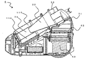
図1は本発明に係る電気掃除機の外観を示す斜視図である。図1に示すように、電気掃除機100は、吸込口体1と、吸引パイプ2と、接続パイプ3と、サクションホース4と、サイクロン方式の掃除機本体5とから構成されている。吸込口体1は床面上の塵埃及び含塵空気を吸い込む。吸込口体1の出口側には真直な円筒状の吸引パイプ2の一端が接続されている。吸引パイプ2の他端には、電気掃除機100の運転を制御する操作スイッチが設置された取手が設けられており、中途にて若干折れ曲がった接続パイプ3の一端が接続されている。接続パイプ3の他端には、可撓性を有する蛇腹状のサクションホース4の一端が接続されている。さらに、サクションホース4の他端には、掃除機本体5が接続されている。掃除機本体5には電源コードが接続されており、電源コードが外部電源に接続されることで、通電し、後述する電動送風機が駆動されて吸引動作を行う。吸込口体1、吸引パイプ2、接続パイプ3およびサクションホース4は、含塵空気を掃除機本体5の外から内部に流入させるための吸引経路の一部を構成する。
Embodiment 1.
FIG. 1 is a perspective view showing an appearance of a vacuum cleaner according to the present invention. As shown in FIG. 1, the vacuum cleaner 100 includes a suction port body 1, a suction pipe 2, a connection pipe 3, a suction hose 4, and a cyclone-type vacuum cleaner body 5. The suction inlet 1 sucks in dust and air containing dust on the floor. One end of a straight cylindrical suction pipe 2 is connected to the outlet side of the suction port body 1. The other end of the suction pipe 2 is provided with a handle in which an operation switch for controlling the operation of the vacuum cleaner 100 is provided, and one end of the connection pipe 3 that is slightly bent in the middle is connected. One end of a flexible bellows-shaped suction hose 4 is connected to the other end of the connection pipe 3. Furthermore, the vacuum cleaner body 5 is connected to the other end of the suction hose 4. A power cord is connected to the vacuum cleaner main body 5. When the power cord is connected to an external power source, electricity is supplied, and an electric blower described later is driven to perform a suction operation. The suction port body 1, the suction pipe 2, the connection pipe 3, and the suction hose 4 constitute a part of a suction path for allowing dust-containing air to flow from the outside to the inside of the cleaner body 5.

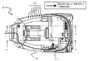
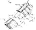
また、図2は図1の電気掃除機の掃除機本体5の斜視図、図3は図1の掃除機本体5の平面図、図4は図2に示す掃除機本体5のa−a断面図、図5は図2に示す掃除機本体5のb−b断面図、図6はサイクロン分離装置50を外した状態の掃除機本体5の上面図、図7は、サイクロン分離装置50の外観を示す斜視図であり、図8はサイクロン分離装置50の前面図である。図9はサイクロン分離装置50の左側面図であり、図10はサイクロン分離装置50の上面図である。図11は図8に示すサイクロン分離装置50のA−A断面図、図12は図8に示すサイクロン分離装置50のB−B矢視断面図、図13は図10に示すサイクロン分離装置50のC−C矢視断面図、図14は図13に示すサイクロン分離装置50のD−D矢視断面図、図15は図13に示すサイクロン分離装置50のE−E矢視断面図、図16は図13に示すサイクロン分離装置50のF−F矢視断面図、図17サイクロン分離装置50塵埃捨て時の斜視図、図18はサイクロン分離装置50の分解斜視図である。   2 is a perspective view of the cleaner body 5 of the electric vacuum cleaner of FIG. 1, FIG. 3 is a plan view of the cleaner body 5 of FIG. 1, and FIG. 4 is a cross-sectional view taken along the line aa of the cleaner body 5 shown in FIG. 5 is a cross-sectional view taken along line bb of the cleaner body 5 shown in FIG. 2, FIG. 6 is a top view of the cleaner body 5 with the cyclone separator 50 removed, and FIG. 7 is an external view of the cyclone separator 50. FIG. 8 is a front view of the cyclone separator 50. FIG. 9 is a left side view of the cyclone separator 50, and FIG. 10 is a top view of the cyclone separator 50. 11 is a cross-sectional view taken along line AA of the cyclone separator 50 shown in FIG. 8, FIG. 12 is a cross-sectional view taken along the line BB of the cyclone separator 50 shown in FIG. 8, and FIG. 14 is a sectional view taken along the arrow D-D of the cyclone separator 50 shown in FIG. 13, and FIG. 15 is a sectional view taken along the line E-E of the cyclone separator 50 shown in FIG. FIG. 18 is a sectional view taken along line FF of the cyclone separator 50 shown in FIG. 13, FIG. 17 is a perspective view of the cyclone separator 50 when dust is discarded, and FIG. 18 is an exploded perspective view of the cyclone separator 50.

図に示すように、掃除機本体5は、吸引風路49とサイクロン分離装置50と排気風路51とフィルター52と電動送風機53と排気口54と、車輪55とから成る。吸引風路49は、その一端が図1に示すサクションホース4に接続され、一次サイクロン部10の側面の外壁に沿って配設され、その他端は、サイクロン分離装置50の一部を構成する一次サイクロン部10の一次流入口11に接続される。サイクロン分離装置50は、一次サイクロン部10と同じくサイクロン分離装置50を構成する二次サイクロン部20の二次排出口25で、掃除機本体5の後方に配置される排気風路51に接続される。排気風路51は、排気風路51と同様に掃除機本体5の後方に配置される電動送風機53と、フィルター52を介して接続される。複数の穴から成る排気口54は、吸引風路49が設置された側とは反対側の側壁に形成されている。   As shown in the figure, the cleaner main body 5 includes a suction air passage 49, a cyclone separator 50, an exhaust air passage 51, a filter 52, an electric blower 53, an exhaust port 54, and wheels 55. One end of the suction air passage 49 is connected to the suction hose 4 shown in FIG. 1 and is disposed along the outer wall of the side surface of the primary cyclone unit 10, and the other end is a primary that forms part of the cyclone separator 50. Connected to the primary inlet 11 of the cyclone unit 10. The cyclone separator 50 is connected to an exhaust air passage 51 disposed at the rear of the cleaner body 5 at the secondary discharge port 25 of the secondary cyclone unit 20 that constitutes the cyclone separator 50 similarly to the primary cyclone unit 10. . The exhaust air passage 51 is connected to the electric blower 53 disposed behind the cleaner body 5 through the filter 52 in the same manner as the exhaust air passage 51. The exhaust port 54 composed of a plurality of holes is formed on the side wall opposite to the side where the suction air passage 49 is installed.

サイクロン分離装置50の詳細な構成を説明する。
サイクロン分離装置50は、一次サイクロン部10と、この一次サイクロン部10と並設され、かつ一次サイクロン部10の下流側に接続された二次サイクロン部20とから構成されている。
A detailed configuration of the cyclone separator 50 will be described.
The cyclone separation device 50 includes a primary cyclone unit 10 and a secondary cyclone unit 20 that is provided in parallel with the primary cyclone unit 10 and connected to the downstream side of the primary cyclone unit 10.

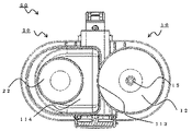
まず、一次サイクロン部10の構成について、図11、図13を用いて説明する。
一次サイクロン部10は、一次流入口11と、一次旋回室12と、0次開口部113と、一次開口部13と、0次ダストケース114と、一次ダストケース14と、一次排出口体15と、一次排出管16と、を備えている。
図13に示すように、一次旋回室12は、その側壁が、略円筒形状の一次円筒部12bと、この一次円筒部12bの下部に設けられ、先端部は一次旋回室12の側壁面の一部を成し、先端に近づくほど径が小さくなる略円錐形状の一次円錐部12aと、一次円錐部12aの先端に形成された一次開口部13とから構成されている。
一次円筒部12bの一部には0次開口部113が形成され、0次開口部113は一次流入口11よりも低い位置に開口し、0次ダストケース114と連通する。一次ダストケース14は、一次ダストケース14に捕集された塵埃を圧縮するために、その上端を一次開口部13よりも上方にまで延在するよう形成されている。
図11に示すように、一次排出口体15は、ほぼ円筒形の中空の円筒部15bと、円筒部15bの下部に設けられ、先端(図11では下方)に近づくほど径が小さくなる円錐部15aと、を備え、円筒部15bと円錐部15aの側壁には多数の孔で構成された一次排出口15cで構成される。また、一次排出口15cの最下部は一次流入口11よりも下方に位置づけられている。
First, the structure of the primary cyclone part 10 is demonstrated using FIG. 11, FIG.
The primary cyclone unit 10 includes a primary inlet 11, a primary swirl chamber 12, a zero-order opening 113, a primary opening 13, a zero-order dust case 114, a primary dust case 14, and a primary discharge port body 15. And a primary discharge pipe 16.
As shown in FIG. 13, the primary swirl chamber 12 is provided with a substantially cylindrical primary cylindrical portion 12 b and a lower portion of the primary cylindrical portion 12 b, and the tip is a portion of the side wall surface of the primary swirl chamber 12. The first conical portion 12a is formed in a substantially conical shape, the diameter of which becomes smaller toward the tip, and the primary opening 13 formed at the tip of the primary cone 12a.
A zero-order opening 113 is formed in a part of the primary cylindrical portion 12 b, and the zero-order opening 113 opens at a position lower than the primary inlet 11 and communicates with the zero-order dust case 114. The primary dust case 14 is formed so that the upper end thereof extends above the primary opening 13 in order to compress the dust collected in the primary dust case 14.
As shown in FIG. 11, the primary discharge port body 15 is provided with a substantially cylindrical hollow cylindrical portion 15b and a conical portion that is provided at the lower portion of the cylindrical portion 15b and decreases in diameter toward the tip (downward in FIG. 11). 15a, and the side wall of the cylindrical portion 15b and the conical portion 15a includes a primary discharge port 15c formed of a large number of holes. Further, the lowermost portion of the primary discharge port 15 c is positioned below the primary inflow port 11.

次に、二次サイクロン部20の構成について、図10、12、13、16を用いて説明する。
二次サイクロン部20は、二次流入口21と、二次旋回室22と、二次開口部23と、二次ダストケース24と、二次排出口25と、二次排出管26とを備えている。
二次旋回室22は、二次旋回室22の側壁面を成し、略円筒形状の二次円筒部22bと、この二次円筒部22bの下部に設けられ、先端に近づくほど径が小さくなる略円錐形状の二次円錐部22aと、二次円錐部22aの先下端に形成された二次開口部23とから構成されている。ここで、二次円錐部22aの先端側は、図13に示すように二次ダストケース24内に突出するように設けられている。
また、上述の0次ダストケース114は、二次ダストケース24及び二次ダストケース24内に突出した二次旋回室22の一部を包囲するように配置されていると共に、一次ダストケース14、二次ダストケース24は1つの部品として形成されている。
Next, the configuration of the secondary cyclone unit 20 will be described with reference to FIGS.
The secondary cyclone unit 20 includes a secondary inlet 21, a secondary swirl chamber 22, a secondary opening 23, a secondary dust case 24, a secondary discharge port 25, and a secondary discharge pipe 26. ing.
The secondary swirl chamber 22 forms a side wall surface of the secondary swirl chamber 22 and is provided in a substantially cylindrical secondary cylindrical portion 22b and a lower portion of the secondary cylindrical portion 22b. The secondary conical portion 22a has a substantially conical shape, and a secondary opening 23 formed at the front lower end of the secondary conical portion 22a. Here, the tip end side of the secondary conical portion 22a is provided so as to protrude into the secondary dust case 24 as shown in FIG.
The zero-order dust case 114 is disposed so as to surround the secondary dust case 24 and a part of the secondary swirl chamber 22 protruding into the secondary dust case 24, and the primary dust case 14, The secondary dust case 24 is formed as one part.

上記の構成において、一次排出管16は、一次排出口15cと二次流入口21とを連通するように設けられているとともに、二次排出管26は、二次排出口25と排気風路51とを連通するように設けられている。これにより、掃除機本体5は、吸込口体1、吸引パイプ2、接続パイプ3、サクションホース4を通じて内部に流入させた含塵空気を、吸引風路49、一次流入口11、一次旋回室12、一次排出口15c、一次排出管16、二次流入口21、二次旋回室22、二次排出口25、二次排出管26を順に通気することで清浄化し、排気風路51、フィルター52、電動送風機53及び排気口54からなる排気経路を経て、掃除機本体5の外部に排出する構造を形成している。   In the above configuration, the primary discharge pipe 16 is provided so as to communicate the primary discharge port 15 c and the secondary inlet 21, and the secondary discharge pipe 26 includes the secondary discharge port 25 and the exhaust air passage 51. Are provided to communicate with each other. As a result, the vacuum cleaner main body 5 has the suction air passage 49, the primary inlet 11, and the primary swirl chamber 12 for the dust-containing air that has flowed through the suction port body 1, the suction pipe 2, the connection pipe 3, and the suction hose 4. The primary exhaust port 15c, the primary exhaust pipe 16, the secondary inflow port 21, the secondary swirl chamber 22, the secondary exhaust port 25, and the secondary exhaust pipe 26 are cleaned by aeration in order, and the exhaust air passage 51 and the filter 52 are cleaned. A structure for discharging to the outside of the cleaner body 5 through an exhaust path including the electric blower 53 and the exhaust port 54 is formed.

次に、本実施の形態1に係わる電気掃除機の動作について、その概要を説明する。
ユーザーによる操作部(図示せず)の操作により電動送風機53に電源が供給されて、電気掃除機100が駆動を開始すると、電動送風機53の吸引力により、吸込口体1から含塵空気が吸引され、吸引パイプ2を通じて、接続パイプ3、サクションホース4の順に吸引経路を流れた後、図6の矢印付きの破線で示されている流れを経て、一次サイクロン部10の一次流入口11へ流入する。一次流入口11へ流入した含塵空気は、一次旋回室12の円筒形の一次円筒部12bの側壁に沿って流入して旋回気流となり、その旋回気流は一次旋回室12の中心軸近傍の強制渦領域とその外周側の準自由渦領域とを形成しながら、その経路構造と重力とにより一次旋回室12の下方に向かって流れていく。
このとき、旋回している含塵空気の中の塵埃には遠心力が作用し、その力によって含塵空気が塵埃と空気に分離される。ここで、遠心力によって分離される塵埃のうち、比重が大きい塵埃(例えば大きな砂や小石等。以下、塵埃Aという)は一次旋回室12に壁面に設けられている0次開口部113から0次ダストケース114内に飛び出して捕集される。また、0次ダストケース114に捕捉された塵埃Aは、前述するように比較的比重が大きいため再飛散しづらく、0次ダストケース114内部の底部に蓄積される。
一方、0次ダストケース114に捕集されなかった塵埃を含む含塵空気は、旋回しながら一次旋回室12の下方、つまり一次円筒部12bから一次円錐部12aに向かって流れていく。一次円錐部12aに進んだ旋回流は、下降するほど、旋回半径(つまり一次円錐部12aの径)が小さくなるため、旋回速度が増大する。これにより、塵埃Aよりも比重が小さい塵埃(例えば綿塵埃は、細かい軽砂等。以下、塵埃Bという)を遠心力によって分離することができ、これにより分離した塵埃Bは一次開口部13から一次ダストケース14内に捕集され蓄積される。
なおここで、一次ダストケース14の形状をD形に形成することにより、D形状の角部分に空気の淀みを作ることができ、この淀みによって塵埃をため易くすることが出来る。
Next, the outline | summary is demonstrated about operation | movement of the vacuum cleaner concerning this Embodiment 1. FIG.
When power is supplied to the electric blower 53 by the operation of an operation unit (not shown) by the user and the electric vacuum cleaner 100 starts driving, dust-containing air is sucked from the suction port body 1 by the suction force of the electric blower 53. After flowing through the suction pipe 2 through the suction pipe 2 in the order of the connection pipe 3 and the suction hose 4, it flows into the primary inlet 11 of the primary cyclone unit 10 through the flow indicated by the broken line with an arrow in FIG. 6. To do. The dust-containing air that has flowed into the primary inlet 11 flows along the side wall of the cylindrical primary cylindrical portion 12 b of the primary swirl chamber 12 to become a swirl airflow, and the swirl airflow is forced near the central axis of the primary swirl chamber 12. While forming the vortex region and the quasi-free vortex region on the outer peripheral side thereof, the vortex region flows toward the lower side of the primary swirl chamber 12 due to the path structure and gravity.
At this time, centrifugal force acts on the dust in the swirling dust-containing air, and the dust-containing air is separated into dust and air by the force. Here, among dusts separated by centrifugal force, dust having a large specific gravity (for example, large sand, pebbles, etc .; hereinafter referred to as dust A) is 0 through the 0th order opening 113 provided on the wall surface of the primary swirl chamber 12. Next, it jumps out into the dust case 114 and is collected. Further, the dust A trapped in the 0th-order dust case 114 has a relatively large specific gravity as described above, and thus is difficult to re-scatter and accumulates at the bottom inside the 0th-order dust case 114.
On the other hand, dust-containing air containing dust that has not been collected in the zero-order dust case 114 flows below the primary swirl chamber 12, that is, from the primary cylindrical portion 12b toward the primary conical portion 12a while swirling. As the swirling flow that has advanced to the primary conical portion 12a descends, the swirling radius (that is, the diameter of the primary conical portion 12a) decreases, so that the swirling speed increases. Accordingly, dust having a specific gravity smaller than that of dust A (for example, cotton dust is fine light sand, etc., hereinafter referred to as dust B) can be separated by centrifugal force, and the separated dust B is separated from the primary opening 13. It is collected and accumulated in the primary dust case 14.
Here, by forming the shape of the primary dust case 14 in a D shape, air stagnation can be created at the corners of the D shape, and dust can be easily collected by this stagnation.

一方、含塵空気から塵埃A及び塵埃Bが除去された空気は、一次サイクロン部10の一次旋回室12の一次円筒部12bの中心軸に沿って上昇し、一次排出口体15の円錐部15a及び円筒部15bに設けられた一次排出口15cを通過して、一次排出管16から二次流入口21を経由して二次サイクロン部20へと流入する。二次流入口21に流入した空気は、二次旋回室22の円筒形の二次円筒部22bの側壁に沿ってほぼ水平に流入して旋回気流となり、その中心軸近傍の強制渦領域とその外周側の準自由渦領域とを形成しながら、その経路構造と重力とにより下向きに流れていく。排気された空気は、その後二次旋回室22の二次円錐部22a内を下降し、その後、上昇して二次排出口25を経由して外部へ排気される。
ここで、各サイクロン部の排出口付近(つまり、一次排出口15c、二次排出口25付近)の各旋回室の径を比べると、二次サイクロン部20の方が径が小さくなるよう構成している。さらに、二次排出口25の開口面積は、一次流入口11の開口面積より小さく構成して、旋回室内部での旋回速度が一次サイクロン部10より二次サイクロン部20の方が早くなるようにしている。これにより、一次サイクロン部10で捕集できなかった微細塵を、二次サイクロン部20の二次ダストケース24に捕集することが可能となる。
On the other hand, the air from which the dust A and the dust B are removed from the dust-containing air rises along the central axis of the primary cylindrical portion 12b of the primary swirl chamber 12 of the primary cyclone unit 10, and the conical portion 15a of the primary discharge port 15 And it passes through the primary discharge port 15c provided in the cylindrical portion 15b and flows into the secondary cyclone unit 20 from the primary discharge pipe 16 via the secondary inlet 21. The air that has flowed into the secondary inlet 21 flows almost horizontally along the side wall of the cylindrical secondary cylindrical portion 22b of the secondary swirl chamber 22 to form a swirling air current. While forming a quasi-free vortex region on the outer peripheral side, it flows downward due to its path structure and gravity. The exhausted air then descends in the secondary conical portion 22 a of the secondary swirl chamber 22 and then rises and is exhausted to the outside via the secondary discharge port 25.
Here, when the diameters of the swirl chambers in the vicinity of the discharge ports of the cyclone units (that is, in the vicinity of the primary discharge port 15c and the secondary discharge port 25) are compared, the diameter of the secondary cyclone unit 20 is configured to be smaller. ing. Further, the opening area of the secondary outlet 25 is configured to be smaller than the opening area of the primary inlet 11 so that the turning speed in the turning chamber is higher in the secondary cyclone part 20 than in the primary cyclone part 10. ing. Thereby, the fine dust that could not be collected by the primary cyclone unit 10 can be collected in the secondary dust case 24 of the secondary cyclone unit 20.

なお、前述したように、一次排出口15cは円筒部15bと円錐部15aに設けた多数の微細な孔で構成している。
これにより、一次サイクロン部10から二次サイクロン部20へ抜ける含塵空気から、一次排出口15cの開口よりも大きい塵埃が通過することを抑制することが出来ると共に、一次排出口15cを円筒部15bと円錐部15aの側壁に設けることで、一次排出口15c周囲を流れる旋回気流によって、一次排出口15cに詰まった塵埃が取り除かれ、塵埃が一次排出口15cに詰まるのを抑制している。また、一次排出口体15の下部を円錐形状にすることにより、一次旋回室12の下方からの上昇流をスムーズに排出することができ、これにより圧損を低減することができる。また、非常に長い糸状の塵埃、例えば髪の毛などが円錐部15aに巻きついてしまっても、円錐部15aの円錐形状により取り除き易い。
As described above, the primary discharge port 15c is constituted by a large number of fine holes provided in the cylindrical portion 15b and the conical portion 15a.
Thereby, it is possible to suppress the passage of dust larger than the opening of the primary discharge port 15c from the dust-containing air that passes from the primary cyclone unit 10 to the secondary cyclone unit 20, and the primary discharge port 15c passes through the cylindrical portion 15b. And the conical portion 15a is provided on the side wall to remove dust clogged in the primary discharge port 15c by the swirling airflow flowing around the primary discharge port 15c, thereby suppressing the clogging of the dust into the primary discharge port 15c. Moreover, by making the lower part of the primary discharge port body 15 into a conical shape, the upward flow from the lower side of the primary swirl chamber 12 can be discharged smoothly, thereby reducing the pressure loss. Even if very long thread-like dust, such as hair, is wound around the conical portion 15a, it is easy to remove due to the conical shape of the conical portion 15a.

このように、比較的遠心力が働き易い塵埃Aを0次ダストケース114で確実に捕集しつつ、塵埃Aよりも遠心力の働きが小さい塵埃Bを一次ダストケース14に捕集することができる。
なお、一般的に、電気掃除機によって吸引される含塵空気の中に含まれる塵埃の割合は、塵埃A、塵埃B、微細塵の順に少なくなる。そのため、塵埃Aを捕集する0次ダストケース114を他のダストケースよりも大きい容量とし、微細塵を捕集する二次ダストケース24を他のダストケースよりも小さい容量とすることで、よりコンパクトなサイクロン分離装置とすることが出来る。
As described above, the dust A whose centrifugal force is smaller than that of the dust A can be collected in the primary dust case 14 while the dust A that is relatively easily subjected to centrifugal force is reliably collected by the zero-order dust case 114. it can.
In general, the ratio of dust contained in the dust-containing air sucked by the vacuum cleaner decreases in the order of dust A, dust B, and fine dust. Therefore, the zero-order dust case 114 that collects the dust A has a larger capacity than the other dust cases, and the secondary dust case 24 that collects the fine dust has a smaller capacity than the other dust cases. A compact cyclone separator can be obtained.

次に、騒音対策について、図13、図14、図15、図17を用いて説明する。
上述したように、二次サイクロン部20は一次サイクロン部10より空気流の旋回速度が速いため集塵効率が高い。しかしながら、旋回速度が速いと空気流風の旋回によって生じる気流音や空気流によって旋回する塵埃と旋回部の内壁面との摩擦音による騒音が大きくなる。したがって、空気流の旋回速度が速い二次サイクロン部20は、集塵効率は一次サイクロン部10よりも高いが、一次サイクロン部10よりも、騒音が大きくなる。
一方、一次サイクロン部10に設けられた一次ダストケース14と0次ダストケース114に流れ込む空気流の量を比較すると、0次ダストケース114では、一次流入口11から流入する含塵空気の空気流の旋回方向に対し、この含塵空気の空気流の接線方向の一次旋回室12の壁面に0次ダストケース114と連通する0次開口部113が形成されているので、0次ダストケース114への空気流の入り込みは微小に抑えることができる。これに対し、一次サイクロン部10の下方に設けられた一次ダストケース14は、旋回する含塵空気の空気流の遠心力に加え、この空気流による下方向への押し込み等の力により分離した塵埃を捕集するようにしているため、0次ダストケース114と比べて、空気流の入り込みが大きくなる。したがって、一次ダストケース14よりも0次ダストケース114のほうが、気流が流れ込むことによって発生する騒音が小さく、また塵埃が壁面に擦れる時に発生する摩擦音も小さくなる。
そこで、図8及び図13に示すように、0次ダストケース114で二次サイクロン部20の少なくとも一部を覆うことで、最も大きい音の発生源である二次サイクロン部20と、使用者が存在する外部空間との間に、サイクロン分離装置50において最も音の発生の少ない空気層と少なくとも一つの壁面を有する部位、つまり0次ダストケース114を設けることで二次サイクロン部20から発生する音を遮音することが出来る。
これにより、サイクロン分離装置50から発生する騒音を抑制することができる。
Next, noise countermeasures will be described with reference to FIGS. 13, 14, 15, and 17. FIG.
As described above, the secondary cyclone unit 20 has a higher dust collection efficiency because the swirl speed of the air flow is faster than that of the primary cyclone unit 10. However, when the turning speed is high, noise caused by the sound of airflow generated by turning of the air current and the friction sound between the dust turning by the air flow and the inner wall surface of the turning portion increases. Therefore, the secondary cyclone unit 20 having a high air flow swirl speed has higher dust collection efficiency than the primary cyclone unit 10, but the noise is larger than that of the primary cyclone unit 10.
On the other hand, when the amount of airflow flowing into the primary dust case 14 and the zeroth dust case 114 provided in the primary cyclone unit 10 is compared, in the zeroth dust case 114, the airflow of the dust-containing air flowing from the primary inlet 11. Since the zero-order opening 113 communicating with the zero-order dust case 114 is formed on the wall surface of the primary swirl chamber 12 in the tangential direction of the air flow of the dust-containing air with respect to the swirling direction of Intrusion of air flow can be suppressed to a minute. On the other hand, the primary dust case 14 provided below the primary cyclone unit 10 has dust separated by a force such as downward pushing by the air flow in addition to the centrifugal force of the air flow of the swirling dust-containing air. Therefore, in comparison with the zero-order dust case 114, the air flow becomes larger. Therefore, in the zero-order dust case 114, the noise generated when the airflow flows is smaller than the primary dust case 14, and the friction sound generated when the dust rubs against the wall surface is also reduced.
Therefore, as shown in FIGS. 8 and 13, by covering at least part of the secondary cyclone unit 20 with the zero-order dust case 114, the secondary cyclone unit 20 that is the source of the loudest sound and the user can Sound generated from the secondary cyclone unit 20 by providing a part having an air layer with least sound generation and at least one wall surface, that is, a zero-order dust case 114 in the cyclone separating apparatus 50 between the existing external space. Can be insulated.
Thereby, the noise which generate | occur | produces from the cyclone separator 50 can be suppressed.

また、図13に示すように、一次排出口15cが、一次旋回室12内に突出している一次排出口体15に形成されており、一次排出口体15の最下部の先端部が、一次流入口11の開口面と対向もしくはこの開口面よりも下方に位置するようにしたので、一次流入口11から流入する含塵空気によって発生する旋回流に、接線方向のみならず、下方向の力が加わり、塵埃は下方向へと導かれやすくなる。よって、一次旋回室12の下方に位置する一次ダストケース14への捕集性能が高くなる。   Moreover, as shown in FIG. 13, the primary discharge port 15c is formed in the primary discharge port body 15 which protrudes in the primary turning chamber 12, and the front-end | tip part of the lowest part of the primary discharge port body 15 is a primary flow. Since it faces the opening surface of the inlet 11 or is positioned below the opening surface, the swirling flow generated by the dust-containing air flowing from the primary inlet 11 has a downward force as well as a tangential direction. In addition, the dust is easily guided downward. Therefore, the collection performance to the primary dust case 14 located under the primary swirl chamber 12 is enhanced.

また、図13に示すように、一次排出口15cの最下部が、0次開口部113の開口面と対向する位置もしくは開口面よりも下方に対向位置するように構成してもよい。これにより、一次流入口11から流入する含塵空気の旋回方向の角度が、0次開口部113よりも下方へと向き、0次開口部113の開口面より下方にて空気流風の旋回が起こりやすくなる。その結果、0次ダストケース114内に直接入り込む含塵空気の量が減少する。つまり、0次ダストケース114内での塵埃の攪拌が少なくなり、摩擦音がより小さくなる。また、0次ダストケース114で旋回する気流の量も少なくなり、気流音も減少する。
このように、0次ダストケース114に発生する騒音量を減らすような構成にすることにより、サイクロン分離装置50から外部に漏れる騒音をより減少させることができる。
Further, as shown in FIG. 13, the lowermost portion of the primary discharge port 15 c may be configured to face the opening surface of the zero-order opening 113 or to face the lower side of the opening surface. Thereby, the angle of the swirling direction of the dust-containing air flowing in from the primary inlet 11 is directed downward from the 0th-order opening 113, and the swirling of the airflow wind occurs below the opening surface of the 0th-order opening 113. It becomes easy. As a result, the amount of dust-containing air that directly enters the zero-order dust case 114 is reduced. That is, the stirring of the dust in the zero-order dust case 114 is reduced, and the friction noise is further reduced. In addition, the amount of airflow swirling in the zero-order dust case 114 is reduced, and the airflow sound is also reduced.
In this way, by making a configuration that reduces the amount of noise generated in the zero-order dust case 114, it is possible to further reduce noise leaking from the cyclone separation device 50 to the outside.

また、図13に示すように、二次サイクロン部20の中でも最も塵埃と壁面の摩擦音が大きい一次旋回室12の一部を、サイクロン分離装置50の中でも最も塵埃と壁面の摩擦音が小さい0次ダストケース114で覆っているので、擦れ音が小さい物で擦れ音が大きい物を覆う形となる。
結果、0次ダストケース内の空気が二次旋回室22から発生する大きな騒音を吸収するため、騒音をかなり効果的に防音でき、サイクロン分離装置50全体の騒音が低下する。
Further, as shown in FIG. 13, a part of the primary swirl chamber 12 having the largest friction sound between the dust and the wall surface in the secondary cyclone unit 20 is replaced with a zeroth order dust having the smallest friction sound between the dust and the wall surface in the cyclone separator 50. Since it is covered with the case 114, an object having a low rubbing sound and an object having a large rubbing sound are covered.
As a result, since the air in the zero-order dust case absorbs a large noise generated from the secondary swirl chamber 22, the noise can be considerably effectively prevented and the noise of the entire cyclone separator 50 is reduced.

また、図15に示すように、0次開口部113が一次旋回室12での旋回流の接線方向が前記一次旋回室12の中心と二次旋回室22の中心とを結ぶ線とほぼ平行になる部位に形成されないように構成する。これにより、旋回流が、直接、0次開口部113に入るのを防ぐことが出来る。そのため、0次ダストケース114への風の流入が少なくなり、0次ダストケース内での塵埃の攪拌が少なくなるため、0次ダストケース114内での塵埃と壁面の摩擦音がより小さくなる。結果、二次サイクロン部20から発生する音をサイクロン分離装置50外に漏らさないようにして、騒音を抑制する効果がより高まる。   Further, as shown in FIG. 15, the tangential direction of the swirling flow in the primary swirl chamber 12 is almost parallel to the line connecting the center of the primary swirl chamber 12 and the center of the secondary swirl chamber 22. It is comprised so that it may not be formed in the site | part which becomes. Thereby, it is possible to prevent the swirling flow from directly entering the 0th-order opening 113. Therefore, the inflow of wind into the 0th-order dust case 114 is reduced, and the stirring of the dust in the 0th-order dust case is reduced, so that the friction noise between the dust and the wall surface in the 0th-order dust case 114 is further reduced. As a result, the sound generated from the secondary cyclone unit 20 is prevented from leaking out of the cyclone separator 50, and the effect of suppressing noise is further enhanced.

また、図13に示す一次サイクロン部10の中でも最も塵埃と壁面の摩擦音が大きい一次旋回室12の一部を、一次サイクロン部10の中でも最も塵埃と壁面の摩擦音が小さい0次ダストケース114で覆うように構成してもよい。即ち、一次旋回室12の一次円筒部12bの下部に一次円錐部12aが設けられ、その先端部は先端に近づくほど径が小さくなるほぼ円錐形状を成しているため、一次旋回室12内の旋回流は、一次円筒部12bから一次円錐部12aに下降する際に気流の方向が曲げられる。そのため、空気中の砂や小石などの塵が一次円錐部12aと激しく当たる。従って、空気の擦れる音及び砂や小石が当たる音が足し合わされて大きな騒音を発する。これに対して、0次ダストケース114は上述したように擦れ音が非常に小さい。
一次旋回室12の一部を、0次ダストケース114で覆うことで、擦れ音が小さい物で擦れ音が大きい物を覆う形となる。
結果、効果的に防音でき、サイクロン分離装置50全体の騒音が低下する。
Further, a part of the primary swirl chamber 12 having the largest friction sound between the dust and the wall surface in the primary cyclone unit 10 shown in FIG. 13 is covered with a zero-order dust case 114 having the smallest friction sound between the dust and the wall surface in the primary cyclone unit 10. You may comprise as follows. That is, since the primary conical part 12a is provided in the lower part of the primary cylindrical part 12b of the primary swirl chamber 12, and the front end part has a substantially conical shape whose diameter decreases toward the front end, When the swirling flow descends from the primary cylindrical portion 12b to the primary conical portion 12a, the direction of the airflow is bent. Therefore, dust such as sand and pebbles in the air violently hits the primary cone portion 12a. Therefore, the sound of air rub and the sound of sand and pebbles are added to generate a loud noise. On the other hand, the zero-order dust case 114 has a very low rubbing sound as described above.
By covering a part of the primary swirl chamber 12 with the zero-order dust case 114, an object with a low rubbing sound and an object with a large rubbing sound are covered.
As a result, sound can be effectively prevented, and the noise of the entire cyclone separator 50 is reduced.

同様に、図13に示す二次サイクロン部20の中でも最も塵埃と壁面の摩擦音が大きい二次旋回室22の一部を、二次サイクロン部20の中でも最も塵埃と壁面の摩擦音が小さい二次ダストケース24で覆うように構成してもよい。即ち、二次旋回室22の二次円筒部22bの下部に二次円錐部22aが設けられ、その先端部は先端に近づくほど径が小さくなるほぼ円錐形状を成しているため、二次旋回室22内の旋回流は、二次円筒部22bから二次円錐部22aに下降する際に気流の方向が曲げられるため、空気中の砂や小石などの塵が二次円錐部22aと激しく当たる。従って、空気の擦れる音及び砂や小石が当たる音が足し合わされて大きな騒音を発する。これに対して、二次ダストケース24は二次円錐部22aの下方に設けられており、二次円錐部22aの先端である二次開口部23で速度が最高になった旋回流は二次開口部23から断面積がより大きい二次ダストケース24に流入する際に今度は速度が遅くなるに従って、二次ダストケース24内では、擦れ音がより小さくなる。
二次旋回室22の一部を二次ダストケース24で覆うことで、擦れ音が小さい物で擦れ音が大きい物を覆う形となる。結果、サイクロン分離装置50全体の騒音が低下する。
Similarly, a part of the secondary swirl chamber 22 having the largest friction sound between the dust and the wall surface in the secondary cyclone unit 20 shown in FIG. 13 is used as a secondary dust having the smallest friction sound between the dust and the wall surface in the secondary cyclone unit 20. You may comprise so that it may cover with the case 24. FIG. That is, since the secondary conical portion 22a is provided in the lower part of the secondary cylindrical portion 22b of the secondary swirl chamber 22, and the tip end portion has a substantially conical shape with a diameter decreasing toward the tip, When the swirling flow in the chamber 22 descends from the secondary cylindrical portion 22b to the secondary conical portion 22a, the direction of the airflow is bent, so that dust such as sand and pebbles in the air violently hits the secondary conical portion 22a. . Therefore, the sound of air rub and the sound of sand and pebbles are added to generate a loud noise. On the other hand, the secondary dust case 24 is provided below the secondary conical portion 22a, and the swirling flow having the highest speed at the secondary opening 23 which is the tip of the secondary conical portion 22a is secondary. As the velocity is reduced this time when flowing into the secondary dust case 24 having a larger cross-sectional area from the opening 23, the rubbing sound becomes smaller in the secondary dust case 24.
By covering a part of the secondary swirl chamber 22 with the secondary dust case 24, an object having a low rubbing sound and an object having a large rubbing sound are covered. As a result, the noise of the entire cyclone separator 50 is reduced.

また、図13及び図14に示すように二次ダストケース24を内包する0次ダストケース114も二次ダストケース24も断面がほぼ円形の円筒である。そこで、双方をほぼ同心円状に設置することで、0次ダストケース114内の気流の速度が均一化され、流れの乱れを抑えることができる。これにより、塵埃と壁面の擦れまたは衝突が均一化されるため、同心円状でない場合に比べ、塵埃と壁面の擦れ又は衝突の不均一による騒音がなくなるため、騒音抑制効果をより一層向上させることができる。
さらに二次旋回室22の二次円錐部22aの先端の二次開口部から二次ダストケース24が延設するように構成してもよい。このとき、二次旋回室22の二次円錐部22aの先端の二次開口部で、二次円錐部22aの軸方向に、二次ダストケース24と接続し、二次開口部と対向する二次ダストケース24の壁側の少なくとも一部を、二次円錐部にて構成する。そして、二次円錐部22aの少なくとも一部を0次ダストケースで覆い、0次開口部113の対面に二次円錐部22aの0次ダストケース114に覆われている部分が位置するように構成する。
これにより、塵埃が0次開口部113から流入した際に、塵埃を円錐に接触させ、軸方向の速度成分とダストケースの延設方向の速度成分を持たせることが出来るため、ダストケースの下方向深部まで塵埃を送り込むことが出来る。
Further, as shown in FIGS. 13 and 14, both the zero-order dust case 114 and the secondary dust case 24 containing the secondary dust case 24 are cylinders having a substantially circular cross section. Therefore, by installing both in a substantially concentric manner, the velocity of the airflow in the zero-order dust case 114 is made uniform, and the flow disturbance can be suppressed. As a result, the rubbing or collision between the dust and the wall surface is made uniform, so that noise due to non-uniform rubbing or collision between the dust and the wall surface is eliminated as compared with the case where the dust and the wall surface are not concentric. it can.
Furthermore, the secondary dust case 24 may be configured to extend from the secondary opening at the tip of the secondary conical portion 22 a of the secondary swirl chamber 22. At this time, the secondary opening at the tip of the secondary conical portion 22a of the secondary swirl chamber 22 is connected to the secondary dust case 24 in the axial direction of the secondary conical portion 22a and is opposed to the secondary opening. At least a part of the secondary dust case 24 on the wall side is formed by a secondary conical portion. Then, at least a part of the secondary conical portion 22a is covered with a zero-order dust case, and a portion of the secondary conical portion 22a covered with the zero-order dust case 114 is located on the opposite side of the zero-order opening 113. To do.
As a result, when dust flows in from the zero-order opening 113, the dust can be brought into contact with the cone so that the speed component in the axial direction and the speed component in the extending direction of the dust case can be provided. Dust can be sent deep in the direction.

また、上述したように、一次排出口15cと二次流入口21が連通されているため、一次サイクロン部10の下流に二次サイクロン部20が直列に接続される。従って、一次サイクロン部10と二次サイクロン部20の双方に流入する空気の量はほぼ同等となる。このとき、図16に示す一次流入口11の断面積を二次流入口21の断面積よりも大きくすることで、一次サイクロン部10内の風速を二次サイクロン部20内の風速よりも遅くすることが出来る。これにより、0次ダストケース内で発生する塵埃と壁面の擦れ音の大きさを2次ダストケース内で発生する塵埃と壁面の擦れ音の大きさよりも小さくすることが出来、騒音を小さくすることが出来る。   Further, as described above, since the primary discharge port 15 c and the secondary inlet 21 are communicated with each other, the secondary cyclone unit 20 is connected in series downstream of the primary cyclone unit 10. Accordingly, the amount of air flowing into both the primary cyclone unit 10 and the secondary cyclone unit 20 is substantially equal. At this time, by making the cross-sectional area of the primary inlet 11 shown in FIG. 16 larger than the cross-sectional area of the secondary inlet 21, the wind speed in the primary cyclone part 10 is made slower than the wind speed in the secondary cyclone part 20. I can do it. As a result, the level of dust and wall rubbing noise generated in the zero-order dust case can be made smaller than the level of dust and wall rubbing noise generated in the secondary dust case, thereby reducing noise. I can do it.

また、図13及び図17に示す一次旋回室12の平均径と二次旋回室22の平均径を異なるように構成しても良い。上述したように一次流入口11の断面積を二次流入口21の断面積よりも大きくすることで、一次サイクロン部10内と二次サイクロン部20内の風速が異なった状態となる。そこで、一次旋回室12の平均径と二次旋回室22の平均径を異なるように構成することで、一次旋回室12と二次旋回室22を旋回する気流の回転数を変更させることが出来、旋回室から発生する音の周波数領域を異なったものとすることが可能となり、音の共鳴を抑制することが出来る。   Moreover, you may comprise so that the average diameter of the primary turning chamber 12 and the average diameter of the secondary turning chamber 22 shown in FIG.13 and FIG.17 may differ. As described above, by making the cross-sectional area of the primary inlet 11 larger than the cross-sectional area of the secondary inlet 21, the wind speeds in the primary cyclone part 10 and the secondary cyclone part 20 are different. Therefore, by configuring the average diameter of the primary swirl chamber 12 and the average diameter of the secondary swirl chamber 22 to be different, it is possible to change the rotation speed of the airflow swirling the primary swirl chamber 12 and the secondary swirl chamber 22. The frequency range of sound generated from the swirl chamber can be made different, and resonance of sound can be suppressed.

なお、上記実施の形態1では、一次排出口15cを一次旋回室12内に突出している一次排出口体15に穿設して形成しているが、これに限るものではなく、二次流入口21と連通する開口部であれば良い。   In the first embodiment, the primary discharge port 15c is formed by drilling into the primary discharge port body 15 protruding into the primary swirl chamber 12, but the present invention is not limited to this. Any opening may be used as long as it is in communication with 21.

1 吸込口体 2 吸引パイプ、3 接続パイプ、4 サクションホース、5 掃除機本体、10 一次サイクロン部、11 一次流入口、12 一次旋回室、12a 一次円錐部、12b 一次円筒部、13 一次開口部、14 一次ダストケース、15 一次排出口体、15a 円錐部、15b 円筒部、15c 一次排出口、20 二次サイクロン部、21 二次流入口、22 二次旋回室、22a 二次円錐部、22b 二次円筒部、23 二次開口部、24 二次ダストケース、25 二次排出口、49 吸引風路、50 サイクロン分離装置、51 排気風路、52 フィルター、53 電動送風機、54 排気口、55 車輪、100 電気掃除機、113 0次開口部、114 0次ダストケース。   DESCRIPTION OF SYMBOLS 1 Suction port body 2 Suction pipe, 3 Connection pipe, 4 Suction hose, 5 Vacuum cleaner main body, 10 Primary cyclone part, 11 Primary inflow port, 12 Primary swirl chamber, 12a Primary cone part, 12b Primary cylindrical part, 13 Primary opening part , 14 Primary dust case, 15 Primary discharge port body, 15a Conical part, 15b Cylindrical part, 15c Primary discharge port, 20 Secondary cyclone part, 21 Secondary inlet, 22 Secondary swirl chamber, 22a Secondary cone part, 22b Secondary cylinder part, 23 Secondary opening part, 24 Secondary dust case, 25 Secondary discharge port, 49 Suction air passage, 50 Cyclone separator, 51 Exhaust air passage, 52 Filter, 53 Electric blower, 54 Exhaust port, 55 Wheel, 100 vacuum cleaner, 1100th order opening, 1140th order dust case.

Claims (4)

外部から吸引した含塵空気が流れ込む流入口と、
前記流入口から吸い込まれた含塵空気を旋回させることで前記含塵空気から塵埃を分離する第一の旋回室および第二の旋回室と、
第一の開口部から、前記第一の旋回室によって流入した塵埃を捕集する第一の集塵部と、
前記第二の旋回室の下方において下向きに設けられた第二の開口部から、前記第二の旋回室によって分離された塵挨を捕集する第二の集塵部と、
前記第一の旋回室および前記第二の旋回室によって少なくとも一部の塵埃が分離された空気を排出する排出口を有するサイクロン部を備え、
前記サイクロン部に搭載される前記第一の集塵部および前記第二の集塵部は、一体で形成されたダストケースが複数に分割されたうちの二つであり、分割された各々の集塵部は異なる気流流入量で塵埃を捕集し、前記第一の旋回室および前記第二の旋回室の中央軸に垂直な断面において接し、少なくとも前記第一の集塵部および前記第二の集塵部の何れかは角部を有し、
前記第一の集塵部が前記第二の集塵部の少なくとも一部を覆うことを特徴とするサイクロン分離装置。
An inlet through which dust-containing air sucked from the outside flows,
A first swirl chamber and a second swirl chamber that separate dust from the dust-containing air by swirling the dust-containing air sucked from the inlet;
A first dust collecting part for collecting dust flowing in by the first swirl chamber from the first opening;
A second dust collecting section for collecting the dust separated by the second swirl chamber from a second opening provided downward in the second swirl chamber;
A cyclone unit having a discharge port for discharging air from which at least part of dust is separated by the first swirl chamber and the second swirl chamber ;
Wherein the first dust collecting section and the second dust collecting portion to be mounted on the cyclone unit is two of the dust case which is formed integrally is divided into a plurality of divided each collecting The dust part collects dust with different airflow inflow amounts, contacts in a cross section perpendicular to the central axis of the first swirl chamber and the second swirl chamber , and at least the first dust collection part and the second dust collection part any of the dust collecting part is to have a corner portion,
The cyclone separator according to claim 1, wherein the first dust collecting part covers at least a part of the second dust collecting part .
前記第一の集塵部は、前記角部を2箇所所有し、D形状に成形されてなることを特徴とする請求項1に記載のサイクロン分離装置。 2. The cyclone separator according to claim 1, wherein the first dust collecting unit has two corners and is formed in a D shape. 前記第一の集塵部は、その上端が前記第一の開口部よりも上方まで延在するよう形成されてなることを特徴とする請求項1または請求項2に記載のサイクロン分離装置。 The cyclone separator according to claim 1 or 2, wherein the first dust collecting part is formed so that an upper end thereof extends to an upper side than the first opening part. 前記請求項1〜3のいずれかに記載のサイクロン分離装置を搭載したことを特徴とする電気掃除機。   A vacuum cleaner equipped with the cyclone separator according to any one of claims 1 to 3.
JP2012049465A 2012-03-06 2012-03-06 Cyclone separation device and vacuum cleaner Active JP5905748B2 (en)

Priority Applications (1)

Application Number Priority Date Filing Date Title
JP2012049465A JP5905748B2 (en) 2012-03-06 2012-03-06 Cyclone separation device and vacuum cleaner

Applications Claiming Priority (1)

Application Number Priority Date Filing Date Title
JP2012049465A JP5905748B2 (en) 2012-03-06 2012-03-06 Cyclone separation device and vacuum cleaner

Related Parent Applications (1)

Application Number Title Priority Date Filing Date
JP2010023274A Division JP4947161B2 (en) 2010-02-04 2010-02-04 Cyclone separation device and vacuum cleaner

Publications (3)

Publication Number Publication Date
JP2012106087A JP2012106087A (en) 2012-06-07
JP2012106087A5 JP2012106087A5 (en) 2012-07-19
JP5905748B2 true JP5905748B2 (en) 2016-04-20

Family

ID=46492335

Family Applications (1)

Application Number Title Priority Date Filing Date
JP2012049465A Active JP5905748B2 (en) 2012-03-06 2012-03-06 Cyclone separation device and vacuum cleaner

Country Status (1)

Country Link
JP (1) JP5905748B2 (en)

Families Citing this family (7)

* Cited by examiner, † Cited by third party
Publication number Priority date Publication date Assignee Title
GB2503257B (en) * 2012-06-20 2014-12-17 Dyson Technology Ltd A cleaning appliance
GB2503251C (en) 2012-06-20 2015-07-15 Dyson Technology Ltd A self righting cleaning appliance
GB2503252B (en) 2012-06-20 2014-12-17 Dyson Technology Ltd A self righting cleaning appliance
GB2503253B (en) 2012-06-20 2014-10-15 Dyson Technology Ltd A cleaning appliance
GB2503254B (en) 2012-06-20 2014-12-17 Dyson Technology Ltd A cleaning appliance
GB2503255B (en) 2012-06-20 2014-10-15 Dyson Technology Ltd A cleaning appliance
JP5954419B2 (en) * 2012-08-15 2016-07-20 三菱電機株式会社 Cyclone separation device and vacuum cleaner provided with the same

Family Cites Families (2)

* Cited by examiner, † Cited by third party
Publication number Priority date Publication date Assignee Title
KR100437369B1 (en) * 2001-01-10 2004-06-25 삼성광주전자 주식회사 Cyclone dust-collecting apparatus for Vacuum Cleaner
KR100500833B1 (en) * 2003-05-24 2005-07-12 삼성광주전자 주식회사 Dust collecting apparatus of vacuum cleaner having plural cyclones

Also Published As

Publication number Publication date
JP2012106087A (en) 2012-06-07

Similar Documents

Publication Publication Date Title
JP4947161B2 (en) Cyclone separation device and vacuum cleaner
JP5306968B2 (en) Electric vacuum cleaner
JP5905748B2 (en) Cyclone separation device and vacuum cleaner
JP5077370B2 (en) Cyclone separation device and vacuum cleaner
JP2005081134A (en) Cyclone separator and vacuum cleaner provided with the same
JP2007117713A (en) Dust collection device of vacuum cleaner
JP4978685B2 (en) Electric vacuum cleaner
KR100546622B1 (en) Dust collector for cleaner
JP5376030B2 (en) Electric vacuum cleaner
JP5126274B2 (en) Cyclone separation device and vacuum cleaner
JP2014083243A (en) Vacuum cleaner with cyclone separation unit
JP4968313B2 (en) Electric vacuum cleaner
JP4941537B2 (en) Electric vacuum cleaner
JP2011224189A (en) Centrifugal dust collector and vacuum cleaner using the same
JP5821980B2 (en) Centrifuge
JP5472417B1 (en) Centrifuge
KR100617093B1 (en) Dust collector for cleaner
JP2016083005A (en) Cyclone separator, and vacuum cleaner
JP5582184B2 (en) Cyclone separation device and vacuum cleaner
JP5472363B2 (en) Electric vacuum cleaner
JP5958631B2 (en) Electric vacuum cleaner
JP5958632B2 (en) Electric vacuum cleaner
JP5880590B2 (en) Electric vacuum cleaner
JP5472359B2 (en) Cyclone separation device and vacuum cleaner
JP5077371B2 (en) Cyclone separation device and vacuum cleaner

Legal Events

Date Code Title Description
A621 Written request for application examination

Free format text: JAPANESE INTERMEDIATE CODE: A621

Effective date: 20120306

A521 Written amendment

Free format text: JAPANESE INTERMEDIATE CODE: A523

Effective date: 20120517

A977 Report on retrieval

Free format text: JAPANESE INTERMEDIATE CODE: A971007

Effective date: 20130226

A131 Notification of reasons for refusal

Free format text: JAPANESE INTERMEDIATE CODE: A131

Effective date: 20130507

A521 Written amendment

Free format text: JAPANESE INTERMEDIATE CODE: A523

Effective date: 20130701

A131 Notification of reasons for refusal

Free format text: JAPANESE INTERMEDIATE CODE: A131

Effective date: 20140121

A521 Written amendment

Free format text: JAPANESE INTERMEDIATE CODE: A523

Effective date: 20140306

A02 Decision of refusal

Free format text: JAPANESE INTERMEDIATE CODE: A02

Effective date: 20140812

A521 Written amendment

Free format text: JAPANESE INTERMEDIATE CODE: A523

Effective date: 20141107

A911 Transfer to examiner for re-examination before appeal (zenchi)

Free format text: JAPANESE INTERMEDIATE CODE: A911

Effective date: 20141114

A912 Re-examination (zenchi) completed and case transferred to appeal board

Free format text: JAPANESE INTERMEDIATE CODE: A912

Effective date: 20150130

A521 Written amendment

Free format text: JAPANESE INTERMEDIATE CODE: A523

Effective date: 20160108

A61 First payment of annual fees (during grant procedure)

Free format text: JAPANESE INTERMEDIATE CODE: A61

Effective date: 20160317

R150 Certificate of patent or registration of utility model

Ref document number: 5905748

Country of ref document: JP

Free format text: JAPANESE INTERMEDIATE CODE: R150

R250 Receipt of annual fees

Free format text: JAPANESE INTERMEDIATE CODE: R250

R250 Receipt of annual fees

Free format text: JAPANESE INTERMEDIATE CODE: R250

R250 Receipt of annual fees

Free format text: JAPANESE INTERMEDIATE CODE: R250

R250 Receipt of annual fees

Free format text: JAPANESE INTERMEDIATE CODE: R250

R250 Receipt of annual fees

Free format text: JAPANESE INTERMEDIATE CODE: R250