JP5913687B2 - Cleaning stick, image forming device - Google Patents
Cleaning stick, image forming device Download PDFInfo
- Publication number
- JP5913687B2 JP5913687B2 JP2015099168A JP2015099168A JP5913687B2 JP 5913687 B2 JP5913687 B2 JP 5913687B2 JP 2015099168 A JP2015099168 A JP 2015099168A JP 2015099168 A JP2015099168 A JP 2015099168A JP 5913687 B2 JP5913687 B2 JP 5913687B2
- Authority
- JP
- Japan
- Prior art keywords
- cleaning
- lens array
- blade
- image forming
- holding member
- Prior art date
- Legal status (The legal status is an assumption and is not a legal conclusion. Google has not performed a legal analysis and makes no representation as to the accuracy of the status listed.)
- Active
Links
Images


Description
この明細書に記載の実施形態は、高さが小さい空間において、長物の清掃に有効な技術に関する。 The embodiment described in this specification relates to a technique effective for cleaning a long object in a space having a small height.
画像形成装置では、光源装置が感光体を露光して感光体上に静電潜像を形成し、現像器が静電潜像を現像して感光体上にトナー像を形成する。画像形成装置は、このトナー像をシートに転写する。 In the image forming apparatus, the light source device exposes the photosensitive member to form an electrostatic latent image on the photosensitive member, and the developing unit develops the electrostatic latent image to form a toner image on the photosensitive member. The image forming apparatus transfers this toner image to a sheet.
画像形成装置において、光源装置としてLEDヘッド (LED:Light Emitting Diode) を用いるものがある。LEDヘッドは、発光素子とレンズアレイとを備える。LEDヘッドのレンズアレイは、感光体に近接した位置にあるため、その光出射面はトナーや紙粉等の異物が付着しやすい。レンズアレイの光出射面が異物により汚れると、画像むらが生じて画像品質の低下を招く。そのため、画像形成装置では、レンズアレイの光出射面の清掃装置が設けられることがある(例えば、特許文献1)。 Some image forming apparatuses use an LED head (LED: Light Emitting Diode) as a light source device. The LED head includes a light emitting element and a lens array. Since the lens array of the LED head is in a position close to the photoconductor, foreign matters such as toner and paper dust are likely to adhere to the light exit surface. If the light exit surface of the lens array is contaminated with foreign matter, image unevenness occurs and image quality is degraded. Therefore, the image forming apparatus may be provided with a cleaning device for the light emitting surface of the lens array (for example, Patent Document 1).
清掃装置では、レンズアレイの光出射面を、布等が設けられた清掃部を往復させることにより清掃する。ところが、清掃装置では、往路で清掃部により捕獲したレンズアレイ上の異物が、復路にて清掃部からレンズアレイ上に再付着するおそれがある。 In the cleaning device, the light emitting surface of the lens array is cleaned by reciprocating a cleaning unit provided with a cloth or the like. However, in the cleaning device, there is a possibility that foreign matters on the lens array captured by the cleaning unit on the forward path may be reattached on the lens array from the cleaning unit on the return path.
特許文献1の清掃装置では、機構が複雑になっており、小型化という観点で改良の余地がある。 In the cleaning device of Patent Document 1, the mechanism is complicated, and there is room for improvement in terms of miniaturization.
この明細書は、高さが小さい空間において、長物の清掃に有効であるとともに、小型化を図ることが可能な技術を提供することを目的とする。 An object of the present specification is to provide a technique that is effective for cleaning a long object in a space having a small height and can be downsized.
一般に、実施形態によれば、清掃棒は、回動部材と、保持部材と、拭き部と、ブレード状部材と、を備える。回動部材は、幅方向両側にある軸部を中心に回動可能に保持される。保持部材は、軸部を保持する。拭き部およびブレード状部材は、回動部材において軸部を挟んで設けられる。ブレード状部材は、回動部材に立設され、可撓性を有する。清掃棒は、清掃面に拭き部が接触した状態で、保持部材が第1方向に移動する際に、拭き部により清掃面上の異物を拭き、ブレード状部材が清掃面に当接した状態で、保持部材が、第1方向と反対方向の第2方向に移動する際に、回動部材のブレード状部材側が清掃面に近接するように回動部材を保持部材に対して回動させる機構により、拭き部が清掃面から離れた状態で、ブレード状部材により清掃面上の異物を掃く。 In general, according to the embodiment, the cleaning rod includes a rotating member, a holding member, a wiping portion, and a blade-like member. The rotating member is held so as to be rotatable about shaft portions on both sides in the width direction. The holding member holds the shaft portion. The wiping portion and the blade-like member are provided across the shaft portion of the rotating member. Blade-like member is erected to the rotation member, it has flexibility. When the holding member moves in the first direction while the wiping part is in contact with the cleaning surface, the cleaning bar wipes foreign matter on the cleaning surface with the wiping part, and the blade-like member is in contact with the cleaning surface. When the holding member moves in the second direction opposite to the first direction, the mechanism rotates the rotating member relative to the holding member so that the blade-like member side of the rotating member is close to the cleaning surface. In the state where the wiping portion is separated from the cleaning surface, the blade-shaped member sweeps foreign matter on the cleaning surface.
以下、実施形態について図面を参照しつつ説明する。
図1は、画像形成装置100の内部構成を示す図である。
画像形成装置100は、MFP(Multi Function Peripheral)であり、読取部31、給紙カセット32、画像形成部33、定着器34、および不図示の制御部を備える。読取部31は、原稿台311上のシートを読み取る。給紙カセット32は、シートを収納する。画像形成部33は、給紙カセット32から取り出されたシートに画像を形成する。
Hereinafter, embodiments will be described with reference to the drawings.
FIG. 1 is a diagram illustrating an internal configuration of the
The
画像形成部33は、感光体10、レンズユニット11、現像器13、駆動ローラ101、1次転写ローラ14、転写ベルト30、2次転写対向ローラ102、および2次転写ローラ103を備える。画像形成装置100の転写定着方式は4連タンデム型となっており、前記各部材10、11、13、14は、Y(イエロー),M(マゼンタ),C(シアン),K(ブラック)の画像形成用毎にある。
The image forming unit 33 includes a
感光体10は、外周面がOPC(Organic Photo Conductor)等の感光面となっており、レンズユニット11および現像器13により感光面上にトナー像が形成され、該トナー像を担持する。
レンズユニット11は、感光体10の周囲にあり、感光体10を露光し感光体10上に静電潜像を形成する。
The outer circumferential surface of the
The
Y〜K用の現像器13は、内部にそれぞれY〜Kのトナーを収容する。現像器13は、内部に収容するトナーをマグネットローラ12により感光体10上の静電潜像に供給する。これにより、現像器13は、Y〜Kの感光体10上の静電潜像を現像し、感光体10上にY〜Kのトナー像を形成する。
The Y to
駆動ローラ101は、転写ベルト30を図1中反時計方向に駆動する。
Y〜Kの感光体10上のトナー像は、各1次転写ローラ14による転写バイアス電圧により転写ベルト30上の同一位置に順次転写され、重ねられる。これにより、転写ベルト30上に1枚のカラートナー像が形成される。
The
The toner images on the Y to
2次転写対向ローラ102および2次転写ローラ103の間には、給紙カセット32からシートが搬送される。転写ベルト30上のトナー像は、2次転写対向ローラ102および2次転写ローラ103の間にて、2次転写ローラ103による転写バイアス電圧によりシートに転写される。画像が転写されたシートは、定着器34にて加熱押圧されて画像が定着した後、排紙部35に排紙される。
A sheet is conveyed from the
不図示の制御部は、CPU(Central Processing Unit)、CPUに読み出される各種のプログラムを格納するメモリ、および各種の機能を実現する専用回路であるASIC(Application Specific Integrated Circuit)を備え、画像形成装置1全体を制御する。 An unillustrated control unit includes a CPU (Central Processing Unit), a memory for storing various programs read by the CPU, and an ASIC (Application Specific Integrated Circuit) that is a dedicated circuit for realizing various functions, and an image forming apparatus Control one whole.
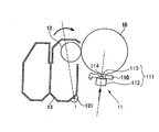
図2は、画像形成時のY〜K用の各現像器13およびLEDヘッド111の位置を示す図、図3は、メンテナンス時のY〜K用の各現像器13およびLEDヘッド111の位置を示す図である。
現像器13は、図2、3に示すように、画像形成装置100のメンテナンス時には、不図示の駆動機構により、回動中心131を中心に感光体10からマグネットローラ12が離間する方向(図3中反時計方向)に回動する。なお、メンテナンス時とは、例えば印刷ジョブの非実行時を指す。
FIG. 2 is a diagram illustrating the positions of the developing
As shown in FIGS. 2 and 3, the developing
レンズユニット11は、LEDヘッド111(光源装置)、清掃棒4(図3)、LEDヘッド111を収納するケース110、および清掃棒4を駆動する不図示の近接離間機構を備える。
The
LEDヘッド111は感光体10を露光する。LEDヘッド111は、図2の紙面垂直方向である走査方向にLEDが配列されたLEDアレイ112(発光素子)と、走査方向に延び、LEDアレイ112の各LEDが出射する各光を感光体10表面に結像させるレンズアレイ113とを備える。レンズアレイ113の感光体10との対向面は、光を出射する光出射面114である。レンズアレイ113は、LEDアレイ112から突出する。
The
不図示の近接離間機構は、画像形成時には、LEDヘッド111を図2に示す感光体10に近接する露光位置に位置づける。近接離間機構は、メンテナンス時には、LEDヘッド111を、感光体10から前記露光位置より離れた図3に示す待機位置に移動させる。
清掃棒4は、メンテナンス時にレンズアレイ113と感光体10との隙間S1に入り込み、レンズアレイ113の光出射面114を清掃する。
A proximity / separation mechanism (not shown) positions the
The cleaning bar 4 enters the gap S1 between the
図4は、清掃棒4の斜視図である。
清掃棒4は、長手状であり、先端部に回動部材5を備える。回動部材5は、後述する第1清掃部6および第2清掃部7を備える(図5参照)。清掃棒4は、不図示の駆動機構によりY方向にスライド移動し、すなわちレンズアレイ113に沿って往復動し、第1、第2清掃部6,7を用いてレンズアレイ113の光出射面114を清掃する。
FIG. 4 is a perspective view of the cleaning rod 4.
The cleaning rod 4 has a longitudinal shape and includes a rotating
以下、清掃棒4の長手方向を+−Y方向とし、Y方向と直交する清掃棒4の幅方向を+−X方向とし、XY方向と直交する方向をZ方向とする。なお、Y方向は走査方向であり、X方向は副走査方向である。+Z方向は、感光体10の径方向において感光体10に近接する方向であり、−Z方向は、感光体10の径方向において感光体10から離間する方向である。
Hereinafter, the longitudinal direction of the cleaning bar 4 is defined as the + -Y direction, the width direction of the cleaning bar 4 perpendicular to the Y direction is defined as the + -X direction, and the direction orthogonal to the XY direction is defined as the Z direction. The Y direction is the scanning direction, and the X direction is the sub-scanning direction. The + Z direction is a direction close to the
図5は、清掃棒4の構成を示す側面図である。
清掃棒4は、回動部材5および保持部材8を備える。
回動部材5は、板状の本体部51と、本体部51の幅方向であるX方向両側にある円柱状の軸部52、およびY方向において軸部52を挟んで軸部52の両側にある第1、第2清掃部6、7を備える。
FIG. 5 is a side view showing the configuration of the cleaning rod 4.
The cleaning bar 4 includes a rotating
The rotating
本体部51において軸部52の+Y方向側には、−Z方向に膨出する円弧状部511があり、軸部52の−Y方向側には、第2清掃部7を−Z方向に支持する支持部512がある。
In the
第1清掃部6は、前記円弧状部511、および円弧状部511の−Z方向側の面に取り付けられる布状部材61を備える。布状部材61は、布や不織布等の柔らかい素材からなる。このように、第1清掃部6は、レンズアレイ113上の異物を拭くことが可能となっている。なお、レンズアレイ113上の異物を拭くとは、第1清掃部6をレンズアレイ113の表面にこすって異物を第1清掃部6に付着させ、異物をレンズアレイ113上から取り去ることを指す。第1清掃部6の−Z方向側の面において+Y方向先端側は、軸部52側(−Y方向先端側)に進むに従って−Z方向に延びる円弧状の乗り上げ面62となっている。
The
このように、第1清掃部6は、円弧状の乗り上げ面62を有する形状であり、レンズアレイ113のエッジ115に当たる際に+Z方向に逃げやすい形状となっている。第1清掃部6のX方向の長さは、レンズアレイ113の光出射面114のX方向の長さと同様の長さである。なお、エッジ115とは、レンズアレイ113の光出射面114における−Y方向端を指す。
As described above, the
第2清掃部7は、前記支持部512、およびブレード状部材71を備える。ブレード状部材71は、平面視矩形の薄板状であり、可撓性を有する。ブレード状部材71は、布状部材61より硬く、かつレンズアレイ113のエッジ115に当接しても削れない程度に硬い。ブレード状部材71のX方向の長さは、レンズアレイ113の光出射面114のX方向の長さと同様の長さである。第2清掃部7は、レンズアレイ113上の異物を掃くことが可能となっている。なお、レンズアレイ113上の異物を掃くとは、第2清掃部7(ブレード状部材71)をレンズアレイ113の表面に当接または近接させながら移動させることにより、異物を移動させることを指す。
The
清掃棒4のホームポジションは、回動部材5がレンズアレイ113の側方に位置する図5の位置である。ブレード状部材71は、清掃棒4がホームポジションにある際、先端がLEDアレイ112の+Z側の面から離れる長さである。
The home position of the cleaning rod 4 is the position in FIG. 5 where the rotating
保持部材8は、回動部材5のX方向両側に位置しY方向に延びる一対の側板81を備える。側板81において回動部材5のX方向両側に位置する部分には長穴部82がある。長穴部82は、Y方向に進むに従ってZ方向に延びる。長穴部82には軸部52が差し込まれる。長穴部82は、軸部52をZ方向側に移動可能に保持する。
The holding
画像形成装置100のメンテナンス時において清掃棒4によりレンズアレイ113を清掃する際、清掃棒4は、まずホームポジションからレンズアレイ113に向かって+Y方向に移動する。ここで、回動部材5は、清掃棒4がホームポジションにあり、第1、第2清掃部6、7がレンズアレイ113に当接していない状態では、支点としての軸部52を中心にシーソのように時計回りや反時計回りに自由に回動できる。
When cleaning the
そのため、清掃棒4が+Y方向(第1方向)に移動し、図6に示すように、第1清掃部6がレンズアレイ113のエッジ115に当接すると、第1清掃部6は、エッジ115に引っ掛かることなくレンズアレイ113上に逃げることができる。しかしながら、この状態では第1清掃部6は、レンズアレイ113の表面にしっかりと抑えつけられてはおらず、十分な清掃能力を発揮できない。
Therefore, when the cleaning rod 4 moves in the + Y direction (first direction) and the
清掃棒4がさらに+Y方向に移動すると、図7に示すように、第2清掃部7(ブレード状部材71)が撓みながらレンズアレイ113上に乗りあげる。第2清掃部7が進行方向の基端側(−Y方向側)に来る姿勢で清掃棒4が+Y方向に移動する図7の往路では、第2清掃部7が撓んで両第1、第2清掃部6、7がレンズアレイ113に接触することとなる。また、軸部52が長穴部82の−Y方向側に案内されて長穴部82から−Z方向側に力を受けることとなる。
When the cleaning rod 4 further moves in the + Y direction, as shown in FIG. 7, the second cleaning unit 7 (blade-like member 71) rides on the
これらにより、往路においては、2つの第1、第2清掃部6、7は圧力が釣り合った状態で共にレンズアレイ113に当接することとなるため、清掃棒4は、これら2つの第1、第2清掃部6、7に十分な荷重を加えながら清掃できる。清掃棒4は、第2清掃部7がレンズアレイ113上から外れる位置まで+Y方向に移動する。
As a result, in the forward path, the two first and
このようにして、往路では、清掃棒4は、第1清掃部6によってレンズアレイ113上の異物を拭くとともに、第2清掃部7によって異物をレンズアレイ113表面外に掃き出し、異物の拭き取りおよび掃き出しの両方を行う。
In this way, in the forward path, the cleaning rod 4 wipes the foreign matter on the
レンズアレイ113上の異物を第1清掃部6で拭くと、異物を拭き取れても第1清掃部6の繊維がレンズアレイ113上に付着する可能性がある。しかしながら、本実施形態では、第1清掃部6でレンズアレイ113上の異物を拭いた後、第2清掃部7でレンズアレイ113上を掃くので、第1清掃部6の繊維がレンズアレイ113に付着することを防止できる。
When the foreign matter on the
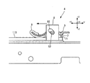
図8は、清掃棒4の復路の清掃状態を示す図である。
清掃棒4は、第2清掃部7をレンズアレイ113より+Y方向側に移動させた後、復路としてレンズアレイ113上を−Y方向(第2方向)へ移動し、レンズアレイ113表面を再度清掃しながらホームポジションに戻る。
FIG. 8 is a diagram showing a cleaning state of the return path of the cleaning rod 4.
The cleaning bar 4 moves the
具体的に、第2清掃部7が進行方向先端側に来る姿勢で清掃棒4が−Y方向に移動すると、進行方向先端側の第2清掃部7(ブレード状部材71)が撓む。同時に、軸部52は、長穴部82の+Y方向に案内されて+Z方向側に移動するとともに、長穴部82から+Z方向側に力を受ける。これらにより、復路では、進行方向基端側の第1清掃部6がレンズアレイ113から浮いた状態となるので、清掃棒4は、第1清掃部6からレンズアレイ113への繊維の付着を防止しながら第2清掃部7のみによりレンズアレイ113上を清掃できる。
Specifically, when the cleaning rod 4 moves in the −Y direction with the
以上のように、本実施形態の清掃棒4は、LEDヘッド111上をスライド移動させるだけで、自動的に第1、第2清掃部6、7がレンズアレイ113上に乗り上げるとともに十分な荷重でレンズアレイ113表面に当接する。そのため、清掃棒4は、これら第1、第2清掃部6、7によりレンズアレイ113上の異物の拭き取りおよび掃き出しを十分に行うことができる。従って、清掃棒4は、感光体10とLEDヘッド111との間の高さが小さい空間において、長物であるLEDヘッド111の清掃に有効である。
As described above, the cleaning rod 4 according to the present embodiment automatically slides on the
また、本実施形態では、第1、第2清掃部6、7をレンズアレイ113上に乗り上げさせるとともに十分な荷重でレンズアレイ113表面に当接させるための機構が簡素であり、かつ感光体10とLEDヘッド111の間の高さの小さい空間内に収まるので、本実施形態は小型化かつ低コスト化を図ることが可能である。
In the present embodiment, the mechanism for causing the first and
(変形例)
前記実施形態では、保持部材8の先端側に、布状部材61を備える第1清掃部6があり、第2清掃部7は、第1清掃部6より保持部材8の基端側にあった。しかしながら、保持部材8の先端側に第2清掃部7があり、第1清掃部6が保持部材8の基端側にあってもよい。この場合、往路で第2清掃部7によりレンズアレイ113上の異物をレンズアレイ113表面外へ掃き出した後、復路で、異物の少なくなったレンズアレイ113上の異物の拭き取りおよび掃き出しを第1、第2清掃部6、7により行うので、第1清掃部6への異物の付着を抑えることができ、第1清掃部6からレンズアレイ113への異物の再付着を抑制できる。
(Modification)
In the embodiment, the
前記実施形態では、穴部82はYZ方向に延びていたが、Z方向に延びていてもよい。前記実施形態では、穴部82は、直線状に延びる部分のみから構成されていたが、曲線状の部分を備えていてもよい。
前記実施形態では、穴部82はスリット状であったが、穴部82は軸部52を回動可能に保持できれば単なる円径であってもよい。
In the embodiment, the
In the embodiment, the
図9は、第1清掃部6Aの乗り上げ面62Aを示す図である。
レンズアレイ113のエッジ115に当たる乗り上げ面62Aは、軸部52側に進むに従って−Z方向に延びるテーパ状であってもよい。
FIG. 9 is a diagram illustrating the
The
図10は、第2清掃部7Aのブレード状部材71Aの正面図、図11は、第2清掃部7Aによる異物の掃き出し方を示す図である。
ブレード状部材71Aは、レンズアレイ113に当たる−Z方向側のエッジ72がXZ方向に傾斜していてもよい。このようにすれば、第2清掃部7は、清掃時にブレード状部材71Aがレンズアレイ113に斜めに当たることとなる。そのため、第2清掃部7は、清掃棒4がY方向に移動することで、自動的に異物をX方向側(例えば+X方向側)に掃くことができ、異物を自動的にレンズアレイ113の表面外に掃き出すことができる。
FIG. 10 is a front view of the blade-
In the blade-
前記実施形態では清掃棒4の清掃対象物としてLEDヘッド111のレンズアレイ113を例示したが、清掃対象物は他のものであってもよい。
本発明は、その精神または主要な特徴から逸脱することなく、他の様々な形で実施することができる。そのため、前述の実施の形態はあらゆる点で単なる例示に過ぎず、限定的に解釈してはならない。本発明の範囲は、特許請求の範囲によって示すものであって、明細書本文には、なんら拘束されない。さらに、特許請求の範囲の均等範囲に属する全ての変形、様々な改良、代替および改質は、すべて本発明の範囲内のものである。
In the above embodiment, the
The present invention can be implemented in various other forms without departing from the spirit or main features thereof. Therefore, the above-described embodiment is merely an example in all respects and should not be interpreted in a limited manner. The scope of the present invention is indicated by the scope of claims, and is not restricted by the text of the specification. Further, all modifications, various improvements, alternatives and modifications belonging to the equivalent scope of the claims are all within the scope of the present invention.
1…画像形成装置、4…清掃棒、5…回動部材、8…保持部材、10…感光体、11…レンズユニット、13…現像器、52…軸部、61…布状部材(拭き部)、71…ブレード状部材、111…LEDヘッド(光源装置)、112…LEDアレイ(発光素子)、113…レンズアレイ、+Y方向・・・第1方向、−Y方向・・・第2方向。 DESCRIPTION OF SYMBOLS 1 ... Image forming apparatus, 4 ... Cleaning stick, 5 ... Rotating member, 8 ... Holding member, 10 ... Photoconductor, 11 ... Lens unit, 13 ... Developing device, 52 ... Shaft part, 61 ... Cloth-like member (wiping part) , 71 ... Blade-like member, 111 ... LED head (light source device), 112 ... LED array (light emitting element), 113 ... Lens array, + Y direction ... first direction, -Y direction ... second direction.
Claims (5)
前記軸部を保持する保持部材と、
前記回動部材において前記軸部を挟んで設けられる拭き部およびブレード状部材と、を備え、
前記ブレード状部材は、前記回動部材に立設され、可撓性を有し、
清掃面に前記拭き部が接触した状態で、前記保持部材が第1方向に移動する際に、前記拭き部により前記清掃面上の異物を拭き、
前記ブレード状部材が前記清掃面に当接した状態で、前記保持部材が、前記第1方向と反対方向の第2方向に移動する際に、前記回動部材の前記ブレード状部材側が前記清掃面に近接するように前記回動部材を前記保持部材に対して回動させる機構により、前記拭き部が前記清掃面から離れた状態で、前記ブレード状部材により前記清掃面上の異物を掃く
ことを特徴とする清掃棒。 A rotating member that is rotatably held around shafts on both sides in the width direction;
A holding member for holding the shaft portion;
A wiping portion and a blade-like member provided across the shaft portion in the rotating member ,
The blade-like member is erected on the rotating member and has flexibility,
When the holding member moves in the first direction with the wiping portion in contact with the cleaning surface, the wiping portion wipes foreign matter on the cleaning surface,
When the holding member moves in the second direction opposite to the first direction with the blade-shaped member in contact with the cleaning surface, the blade-shaped member side of the rotating member is the cleaning surface. A mechanism for rotating the rotating member relative to the holding member so as to be close to the cleaning member, and cleaning the foreign matter on the cleaning surface by the blade-like member in a state where the wiping portion is separated from the cleaning surface. Characteristic cleaning stick.
前記保持部材は、前記第1方向に延び、前記回動部材は、前記保持部材の前記一方側にあることを特徴とする清掃棒。 The cleaning stick according to claim 1,
The cleaning rod according to claim 1, wherein the holding member extends in the first direction, and the rotating member is on the one side of the holding member.
前記ブレード状部材の延びる第3方向の先端縁は、前記第3方向に対して傾いていることを特徴とする清掃棒。 In the cleaning stick according to claim 1 or 2,
3. A cleaning rod, wherein a tip end edge in the third direction in which the blade-shaped member extends is inclined with respect to the third direction.
前記レンズアレイの光出射面を清掃する請求項1から請求項3のいずれかに記載の前記清掃棒と、を備えることを特徴とする画像形成装置。 A light source device comprising: a light emitting element extending in the first direction; and a lens array extending in the first direction and through which light emitted from the light emitting element passes.
An image forming apparatus comprising: the cleaning rod according to claim 1, wherein the light emitting surface of the lens array is cleaned.
トナー像を担持する感光体と、
前記感光体の周囲にあり、前記感光体を露光し前記感光体上に静電潜像を形成する前記光源装置と、
前記静電潜像を現像し、前記感光体上に前記トナー像を形成する現像器と、
前記光源装置を、露光位置と、前記感光体から前記露光位置より離れた待機位置とに移動させる近接離間機構と、を備える
ことを特徴とする画像形成装置。
The image forming apparatus according to claim 4.
A photoreceptor carrying a toner image;
The light source device that is around the photoconductor and exposes the photoconductor to form an electrostatic latent image on the photoconductor;
A developing device for developing the electrostatic latent image and forming the toner image on the photoreceptor;
An image forming apparatus comprising: a light source device that moves to an exposure position and a stand-by position that moves away from the photosensitive member to a standby position that is separated from the exposure position.
Applications Claiming Priority (2)
| Application Number | Priority Date | Filing Date | Title |
|---|---|---|---|
| US201261622706P | 2012-04-11 | 2012-04-11 | |
| US61/622,706 | 2012-04-11 |
Related Parent Applications (1)
| Application Number | Title | Priority Date | Filing Date |
|---|---|---|---|
| JP2013049310A Division JP5749756B2 (en) | 2012-04-11 | 2013-03-12 | Image forming apparatus |
Publications (2)
| Publication Number | Publication Date |
|---|---|
| JP2015193255A JP2015193255A (en) | 2015-11-05 |
| JP5913687B2 true JP5913687B2 (en) | 2016-04-27 |
Family
ID=49588800
Family Applications (2)
| Application Number | Title | Priority Date | Filing Date |
|---|---|---|---|
| JP2013049310A Active JP5749756B2 (en) | 2012-04-11 | 2013-03-12 | Image forming apparatus |
| JP2015099168A Active JP5913687B2 (en) | 2012-04-11 | 2015-05-14 | Cleaning stick, image forming device |
Family Applications Before (1)
| Application Number | Title | Priority Date | Filing Date |
|---|---|---|---|
| JP2013049310A Active JP5749756B2 (en) | 2012-04-11 | 2013-03-12 | Image forming apparatus |
Country Status (1)
| Country | Link |
|---|---|
| JP (2) | JP5749756B2 (en) |
Families Citing this family (1)
| Publication number | Priority date | Publication date | Assignee | Title |
|---|---|---|---|---|
| JP6867772B2 (en) * | 2016-10-06 | 2021-05-12 | キヤノン株式会社 | Image forming device |
Family Cites Families (8)
| Publication number | Priority date | Publication date | Assignee | Title |
|---|---|---|---|---|
| JP3467594B2 (en) * | 1992-03-16 | 2003-11-17 | セイコーエプソン株式会社 | Ink jet recording device |
| JP4349027B2 (en) * | 2003-07-24 | 2009-10-21 | 富士ゼロックス株式会社 | Image forming apparatus and print head |
| JP2006139000A (en) * | 2004-11-11 | 2006-06-01 | Seiko Epson Corp | Image forming apparatus |
| JP2008018690A (en) * | 2006-07-14 | 2008-01-31 | Murata Mach Ltd | Image forming apparatus |
| JP2009122427A (en) * | 2007-11-15 | 2009-06-04 | Fuji Xerox Co Ltd | Image forming apparatus |
| JP2010105342A (en) * | 2008-10-31 | 2010-05-13 | Ricoh Co Ltd | Optical writing device, and image forming device |
| JP2010234558A (en) * | 2009-03-30 | 2010-10-21 | Kyocera Mita Corp | Image forming apparatus |
| JP2012025130A (en) * | 2010-07-27 | 2012-02-09 | Ricoh Co Ltd | Image forming apparatus |
-
2013
- 2013-03-12 JP JP2013049310A patent/JP5749756B2/en active Active
-
2015
- 2015-05-14 JP JP2015099168A patent/JP5913687B2/en active Active
Also Published As
| Publication number | Publication date |
|---|---|
| JP2013216091A (en) | 2013-10-24 |
| JP2015193255A (en) | 2015-11-05 |
| JP5749756B2 (en) | 2015-07-15 |
Similar Documents
| Publication | Publication Date | Title |
|---|---|---|
| JP6277619B2 (en) | Image forming apparatus and image carrier unit | |
| JP6092716B2 (en) | Cleaning device and image forming apparatus using the same | |
| JP4349027B2 (en) | Image forming apparatus and print head | |
| JP4963649B2 (en) | Image forming apparatus | |
| JP2007178560A (en) | Image forming apparatus | |
| JP5913687B2 (en) | Cleaning stick, image forming device | |
| JP5452010B2 (en) | Image forming apparatus | |
| JP2011013306A (en) | Image forming apparatus | |
| JP5264609B2 (en) | Cleaning device | |
| JP2013120294A (en) | Fixing device and image forming apparatus | |
| JP2004333799A (en) | Image forming apparatus | |
| US9201378B2 (en) | Cleaning unit, process cartridge incorporating same, and image forming apparatus incorporating same | |
| JP5657724B2 (en) | Cleaning rod, lens unit, image forming device | |
| JP5657725B2 (en) | Cleaning rod, lens unit, image forming device | |
| JP5303252B2 (en) | Cleaning device and image forming apparatus equipped with the same | |
| JP5875022B2 (en) | Image forming apparatus | |
| JP5512573B2 (en) | Charging device and image forming apparatus | |
| JP5483017B2 (en) | Belt device and image forming apparatus | |
| CN106200314B (en) | Static electricity removing device and image forming apparatus | |
| JP2015045739A (en) | Image forming apparatus | |
| JP2007148246A (en) | Exposure device and image forming apparatus | |
| JP5723759B2 (en) | Static eliminating unit, drum unit including the same, and image forming apparatus | |
| JP2010152082A (en) | Application device, process cartridge, cleaning unit, and image forming apparatus | |
| JPH08123154A (en) | Image forming device | |
| JP2006098905A (en) | Image forming apparatus |
Legal Events
| Date | Code | Title | Description |
|---|---|---|---|
| A131 | Notification of reasons for refusal |
Free format text: JAPANESE INTERMEDIATE CODE: A131 Effective date: 20151201 |
|
| A521 | Written amendment |
Free format text: JAPANESE INTERMEDIATE CODE: A523 Effective date: 20160120 |
|
| TRDD | Decision of grant or rejection written | ||
| A01 | Written decision to grant a patent or to grant a registration (utility model) |
Free format text: JAPANESE INTERMEDIATE CODE: A01 Effective date: 20160315 |
|
| A61 | First payment of annual fees (during grant procedure) |
Free format text: JAPANESE INTERMEDIATE CODE: A61 Effective date: 20160401 |
|
| R150 | Certificate of patent (=grant) or registration of utility model |
Ref document number: 5913687 Country of ref document: JP Free format text: JAPANESE INTERMEDIATE CODE: R150 |