JP5913612B2 - Insetable device combination - Google Patents
Insetable device combination Download PDFInfo
- Publication number
- JP5913612B2 JP5913612B2 JP2014540334A JP2014540334A JP5913612B2 JP 5913612 B2 JP5913612 B2 JP 5913612B2 JP 2014540334 A JP2014540334 A JP 2014540334A JP 2014540334 A JP2014540334 A JP 2014540334A JP 5913612 B2 JP5913612 B2 JP 5913612B2
- Authority
- JP
- Japan
- Prior art keywords
- locking
- module
- casing
- socket
- fitting
- Prior art date
- Legal status (The legal status is an assumption and is not a legal conclusion. Google has not performed a legal analysis and makes no representation as to the accuracy of the status listed.)
- Active
Links
- 230000008878 coupling Effects 0.000 claims description 27
- 238000010168 coupling process Methods 0.000 claims description 27
- 238000005859 coupling reaction Methods 0.000 claims description 27
- 230000015572 biosynthetic process Effects 0.000 claims description 3
- 238000000034 method Methods 0.000 claims description 2
- 208000019695 Migraine disease Diseases 0.000 claims 1
- 206010027599 migraine Diseases 0.000 claims 1
- 238000011161 development Methods 0.000 description 2
- 230000018109 developmental process Effects 0.000 description 2
- 230000001419 dependent effect Effects 0.000 description 1
- 230000013011 mating Effects 0.000 description 1
- 230000001681 protective effect Effects 0.000 description 1
- 230000007704 transition Effects 0.000 description 1
Images


Classifications
-
- H—ELECTRICITY
- H01—ELECTRIC ELEMENTS
- H01R—ELECTRICALLY-CONDUCTIVE CONNECTIONS; STRUCTURAL ASSOCIATIONS OF A PLURALITY OF MUTUALLY-INSULATED ELECTRICAL CONNECTING ELEMENTS; COUPLING DEVICES; CURRENT COLLECTORS
- H01R13/00—Details of coupling devices of the kinds covered by groups H01R12/70 or H01R24/00 - H01R33/00
- H01R13/62—Means for facilitating engagement or disengagement of coupling parts or for holding them in engagement
- H01R13/627—Snap or like fastening
- H01R13/6271—Latching means integral with the housing
- H01R13/6272—Latching means integral with the housing comprising a single latching arm
-
- H—ELECTRICITY
- H01—ELECTRIC ELEMENTS
- H01R—ELECTRICALLY-CONDUCTIVE CONNECTIONS; STRUCTURAL ASSOCIATIONS OF A PLURALITY OF MUTUALLY-INSULATED ELECTRICAL CONNECTING ELEMENTS; COUPLING DEVICES; CURRENT COLLECTORS
- H01R9/00—Structural associations of a plurality of mutually-insulated electrical connecting elements, e.g. terminal strips or terminal blocks; Terminals or binding posts mounted upon a base or in a case; Bases therefor
- H01R9/22—Bases, e.g. strip, block, panel
- H01R9/24—Terminal blocks
- H01R9/26—Clip-on terminal blocks for side-by-side rail- or strip-mounting
- H01R9/2608—Fastening means for mounting on support rail or strip
-
- H—ELECTRICITY
- H01—ELECTRIC ELEMENTS
- H01R—ELECTRICALLY-CONDUCTIVE CONNECTIONS; STRUCTURAL ASSOCIATIONS OF A PLURALITY OF MUTUALLY-INSULATED ELECTRICAL CONNECTING ELEMENTS; COUPLING DEVICES; CURRENT COLLECTORS
- H01R9/00—Structural associations of a plurality of mutually-insulated electrical connecting elements, e.g. terminal strips or terminal blocks; Terminals or binding posts mounted upon a base or in a case; Bases therefor
- H01R9/22—Bases, e.g. strip, block, panel
- H01R9/24—Terminal blocks
- H01R9/2425—Structural association with built-in components
- H01R9/2441—Structural association with built-in components with built-in overvoltage protection
Landscapes
- Details Of Connecting Devices For Male And Female Coupling (AREA)
- Connector Housings Or Holding Contact Members (AREA)
Description
本発明は、はめ込みモジュールと、装置ソケットとを備え、この装置ソケットのはめ込みモジュールへの係止のために、ケーシング側で、係止アームが端側に設けられた係止フックに結合されており、この係止フックが、圧力の印加によって離脱可能な係止結合部の形成のための装置ソケットのカウンタ係止部と相互に作用する、はめ込み可能な装置コンビネーションに関するものである。はめ込みモジュールは、特には過電流保護スイッチである。 The present invention includes a fitting module and a device socket, and for locking the device socket to the fitting module, a locking arm is coupled to a locking hook provided on an end side on the casing side. The locking hook interacts with a counter-locking part of the device socket for the formation of a locking connection which can be detached by the application of pressure, and relates to a snap-fit device combination. The inset module is in particular an overcurrent protection switch.
国際公開第95/12905号には、はめ込みモジュールの互いに対向する側に設けられた複数の係止突起を有する、はめ込みモジュールとU字状の下部との間の係止結合部を有するはめ込み可能な装置コンビネーションが開示されている。上記係止突起は、外方へ突出しているとともに、下部におけるカウンタ係止部に係止可能となっている。各係止突起は、弾性的に内側へ変形可能かつヒンジ結合部を形成しつつ一体的にはめ込みモジュールケーシングへ取り付け可能なクリックアームにおけるはめ込みモジュールの側壁部に位置している。ヒンジ結合部は、U字状の下部の底部に対向するはめ込みモジュールの下側に位置している。クリックアームにおける操作突起への押圧により、係止結合を解除することが可能である。 WO 95/12905 has a locking connection between a fitting module and a U-shaped lower part, with a plurality of locking projections provided on opposite sides of the fitting module. A device combination is disclosed. The locking projection protrudes outward and can be locked to the counter locking portion at the lower portion. Each locking projection is located on the side wall portion of the fitting module in the click arm that can be elastically deformed inward and can be integrally attached to the fitting module casing while forming a hinge joint. The hinge coupling part is located on the lower side of the fitting module facing the bottom of the U-shaped lower part. The locking connection can be released by pressing the operation projection on the click arm.
独国特許出願公開第102006033274号明細書には、過電圧保護要素を収容するはめ込みモジュールの収容のための、ソケット状かつU字状の下部を有するはめ込み可能な装置コンビネーションが開示されており、ここでも、同様にはめ込みモジュールの互いに対向する両端面側において、それぞれはめ込みモジュールにおける対応するアンダーカットされた係止凹部へ係合する係止突起を含む複数の係止手段が設けられている。はめ込みモジュール側の複数の係止突起はそれぞれ付勢下にあるヒンジ結合部に形成されており、係止結合は、はめ込みモジュールの端面側におけるヒンジ結合部への押圧により解除可能である。ソケット状の下部へ向けられた操作面への押圧力の印加により、ソケット状の下部の複数の係止凹部を有する両側の係止結合を解除するために、モジュールケーシングへ向けた係止突起の旋回が生じる。 German Offenlegungsschrift 102006033274 discloses an insetable device combination with a socket-like and U-shaped lower part for accommodating a telescoping module for accommodating an overvoltage protection element, also here Similarly, a plurality of locking means including locking protrusions that engage with corresponding undercut locking recesses in the fitting module are provided on the opposite end surfaces of the fitting module. A plurality of locking projections on the fitting module side are formed on the hinge coupling portions under biasing, and the locking coupling can be released by pressing the hinge coupling portions on the end face side of the fitting module. In order to release the locking coupling on both sides having a plurality of locking recesses in the socket-like lower part by applying a pressing force to the operation surface directed to the socket-like lower part, A turn occurs.
本発明の課題は、わずかな手間で実現され、かつ、容易に操作可能な係止結合部を有するはめ込み可能な装置コンビネーションを提供することを基礎としている。 The object of the present invention is based on providing an insetable device combination with a locking coupling that can be easily operated and is realized with little effort.
上記課題は、本発明に基づき、請求項1の特徴によって達成される。好ましい形態及び発展形成は、各従属請求項の対象である。
This object is achieved according to the invention by the features of
これについて、はめ込み可能な装置コンビネーションは、装置ソケットと、保護スイッチ要素を収容するはめ込みモジュールとを含んでおり、このはめ込みモジュールのモジュールケーシングにおいては、装置ソケットへの方向へ延びている係止アームが、端部側に設けられた係止フックに結合されている。特に好ましくは、単に唯一の係止アームが設けられている。その突出状の結合箇所は、装置ソケットから離間した上側のケーシング範囲において、モジュールケーシングの短辺側の1つに位置している。 In this regard, the telescoping device combination includes a device socket and a telescoping module that houses a protective switch element, the module casing of the telescoping module having a locking arm extending in the direction towards the device socket. , And is coupled to a locking hook provided on the end side. Particularly preferably, only one locking arm is provided. The projecting coupling point is located on one of the short sides of the module casing in the upper casing area spaced from the device socket.
はめ込まれた装置コンビネーションにおいては、はめ込みモジュールがソケット底部に側方において側面で並ぶはめ込み面の間に収容されており、はめ込み面のうちいずれかにおいてのみ、はめ込みモジュールの係止フックに係止可能な、係止結合部を形成するためのカウンタ係止部が設けられている。ケーシング側の係止アームの結合部とこの係止アームの係止フックの間には軸支点が形成されており、その結果、この軸支点と係止フックとの間における係止アームの振れ部分と、軸支点と係止アームのケーシング側の結合部との間における、係止アームにおける押圧力の印加のための操作部分とが生じる。そのため、係止アームの振れ部分が軸支点周りに振れ、係止結合が解除される。 In the fitted device combination, the inset module is housed between the inset surfaces that are lined laterally at the bottom of the socket and can be locked to the inset hooks of the inset module only on one of the inset surfaces A counter locking portion for forming a locking coupling portion is provided. A shaft fulcrum is formed between the coupling portion of the locking arm on the casing side and the locking hook of the locking arm, and as a result, the swing arm swinging portion between the shaft fulcrum and the locking hook. And an operating portion for applying a pressing force on the locking arm between the shaft fulcrum and the coupling portion on the casing side of the locking arm. Therefore, the swinging portion of the locking arm swings around the shaft fulcrum, and the locking connection is released.
軸支点は、側方でモジュールケーシングに設けられつつ係止アームの背面側に位置する突出部によって形成されている。この突出部は、特に一部材として係止アームに結合されることが可能である。場合によっては、モジュールケーシング及び係止アームに設けられた突出部によって旋回継手が形成される。一方、係止アームが素材結合式の結合なしに単に突出部上に載置されている場合には、ここに回転中心点あるいは線状の軸支点が形成される。 The shaft fulcrum is formed by a protrusion that is provided on the side of the module casing while being provided on the side of the locking arm. This protrusion can in particular be connected to the locking arm as one member. In some cases, a swivel joint is formed by protrusions provided on the module casing and the locking arm. On the other hand, when the locking arm is simply placed on the protruding portion without the material coupling type coupling, a rotation center point or a linear shaft fulcrum is formed here.
好ましくはモジュールケーシングの上側において、かつ、そこで側方において設けられた係止アームは、軸支点を越えて延びており、その係止フックにおいてソケット側のカウンタ係止部(カウンタ係止フック)の後方あるいは下方で終わっている。このとき、好ましくは装置ソケットに対向する下側の半部において軸支点が設けられており、そのため、軸支点と係止フックの間の係止アームの振れ部分が、係止アームのケーシング側の結合部と軸支点の間に形成された係止アームの操作部分よりも短くなっている。はめ込みモジュール側の係止フックは、はめ込みモジュールのモジュールケーシングに対向する係止アームの内側又は後ろ側に位置しているとともに、モジュールケーシングの対応する側面へ向けて整向されている。ソケット側のカウンタ係止部のカウンタ係止面は、モジュールケーシングから離れるように外方へ延びている。 Preferably, the locking arm provided on the upper side of the module casing and on the side thereof extends beyond the shaft fulcrum, and the locking hook has a counter locking portion (counter locking hook) on the socket side. Ends backward or downward. At this time, a shaft fulcrum is preferably provided in the lower half facing the device socket, so that the swinging portion of the locking arm between the shaft fulcrum and the locking hook is located on the casing side of the locking arm. It is shorter than the operation part of the locking arm formed between the coupling part and the pivot point. The locking hook on the fitting module side is located on the inner side or the rear side of the locking arm facing the module casing of the fitting module and is oriented toward the corresponding side surface of the module casing. The counter locking surface of the socket side counter locking portion extends outwardly away from the module casing.
係止アームは、対応するケーシング短辺側において、係止アームとケーシング短辺側の間にケーシング空間部が形成されるようにモジュールケーシングへ設けられている。このケーシング空間部及びそこで軸支点の下方に位置する、装置ソケットに対向する空間部分には、ソケット側のカウンタ係止部が係止結合部を形成しつつ突出している。これにより、好ましくは、係止アームも、又その係止フックも、ソケット側のカウンタ係止部との係止結合になく、又、はめ込まれた状態でも、又はめ込まれていない状態でも、はめ込みモジュールのモジュールケーシングの側面を越えて突出しないことが達成される。 The locking arm is provided on the module casing such that a casing space is formed between the locking arm and the casing short side on the corresponding casing short side. A counter locking portion on the socket side protrudes while forming a locking coupling portion in this casing space portion and a space portion located below the pivot point and facing the apparatus socket. Thus, preferably, the locking arm and its locking hook are not in a locking connection with the counter locking portion on the socket side, and are engaged even when they are fitted or not. It is achieved that the module does not protrude beyond the side of the module casing.
合目的な形態においては、軸支点の範囲における係止アームが、係止アームの振れ部分がモジュールケーシングあるいはその側面に対して係止アームの操作部分よりもよりわずかな間隔を有するようにオフセットされている。これにより、係止アームの外部輪郭及び係止結合部のはめ込みモジュールの外部輪郭への特に厳密な適合がもたらされる。 In a suitable form, the locking arm in the range of the pivot point is offset so that the swinging part of the locking arm is slightly spaced relative to the module casing or its side than the operating part of the locking arm. ing. This results in a particularly tight fit of the outer contour of the locking arm and the outer contour of the fitting module of the locking joint.
装置ソケットはソケット内部において外部からアクセス可能な端子に導電的に結合可能な複数のコンタクト要素を備えており、これらコンタクト要素は、装置ソケットのソケット底部を越えてアクセス可能であるとともに、底部側ではめ込みモジュールから突出するコンタクト要素に対応する。例えば、5つのこのようなはめ込みコンタクト結合部が設けられている。 The device socket includes a plurality of contact elements that are conductively connectable to externally accessible terminals within the socket, the contact elements being accessible beyond the socket bottom of the device socket and on the bottom side. Corresponds to the contact element protruding from the inset module. For example, five such inset contact couplings are provided.
好ましい発展形成においては、装置コンビネーションがはめ込みモジュールとケーシングソケットの間にはめ込みコードを備えている。このはめ込みコードは、適切には、はめ込みモジュール側の複数のはめ込みポケット部と、はめ込みモジュールのこれらはめ込みポケット部に形状結合式に係合するソケット側の複数のコード化中空ピンとによって形成されている。はめ込みポケット部は、予定破断箇所を形成しつつ設けられた好ましくはピン状の複数のコード化要素を備えており、これらコード化要素は、個々に折り取られ得るものである。装置ソケットのソケット底部から突出する、対応するソケット側のコード化中空ピンは、それぞれ1つの中空室を備えており、この中空室は、コード化の目的のためにロック可能となっている。このために、例えば準備されたコード化要素が個々のコード化中空ピンへはめ込まれることが可能である。場合によっては、適当なコード化要素がそれぞれのはめ込みポケット部から取り出されないはめ込みモジュールを、コード化された装置ソケットと組み合わせることができない。 In a preferred development, the device combination comprises a telescoping cord between the telescoping module and the casing socket. The telescoping cord is suitably formed by a plurality of telescoping pockets on the telescoping module side and a plurality of coded hollow pins on the socket side that engage form-engaged with the mating pockets of the telescoping module. The inset pocket part comprises a plurality of preferably pin-like coding elements provided to form a predetermined breaking point, and these coding elements can be folded individually. The corresponding socket-side coded hollow pins projecting from the socket bottom of the device socket each have one hollow chamber, which can be locked for coding purposes. For this purpose, for example, prepared coding elements can be fitted into individual coded hollow pins. In some cases, an inset module in which the appropriate encoding element is not removed from the respective inset pocket cannot be combined with the encoded device socket.
以下に、本発明の複数の実施例を図面に基づいて詳細に説明する。 Below, a plurality of examples of the present invention are described in detail based on a drawing.
互いに対応する部材には、全ての図において同一の符号が付されている。 The members corresponding to each other are denoted by the same reference numerals in all the drawings.
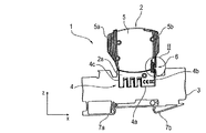
図1には、はめ込みモジュール2と、ソケット底部4aの側方で側面に並ぶ2つのはめ込み面4b及び4cを有するU字状のはめ込み範囲あるいははめ込み部分4を備えた装置ソケット3とを有する装置コンビネーション1が示されている。はめ込みモジュール2は、実質的に係合するようにはめ込み範囲4によって収容されているとともに、そのはめ込みシャフト(はめ込み範囲又ははめ込み部分)2aにおいて一方ではソケット底部4aと、他方では側面4b,4cに密接している。はめ込みモジュール2は、互いに対向する短辺側又はケーシング短辺側5a及び5bを有するモジュールケーシング5を備えている。
FIG. 1 shows an apparatus combination comprising an
両「短辺側」のうちの1つ5bにおいてのみ、はめ込みモジュール2と装置ソケット3の間に係止結合部6が存在し、これを用いて、はめ込みモジュール2が離脱可能に装置ソケット3に係止されている。装置ソケット3には、その底部側において、装置コンビネーションのDINレール取り付けのための保持輪郭部又はクリック輪郭部7a,7bが設けられている。
Only at one of the “short sides” 5b, there is a
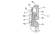
係止結合部6は、図2において、図1のII部分として拡大された縮尺で示されている。はめ込みモジュール2は、そのケーシング短辺側5bにおいて、係止結合部6に関与する係止アーム8を備えており、この係止アームは、ケーシング短辺側5bに沿ってz方向において装置ソケット3へ向けて延びているとともに、自由端側において係止フック8aを備えている。この係止フック8aは、その不図示の係止面においてはモジュールケーシング5へ、このモジュールケーシングにおけるそのケーシング短辺側5bにおいては短辺側の、以下ではケーシング中間壁部又は5cとして表わされるものへ向けて整向されている。この内壁部5cとこれに対向する係止アーム8の背面側8bの間には、ケーシング空間部9(図3及び図4)の下側の空間部9aが形成されている。ケーシング空間部9のこの下側の空間部9aには、カウンタ係止部10が、その係止シャフト10aにおける自由端側で形成されたカウンタ係止フック10bにおいて突出している。
The locking
カウンタ係止部10は、ソケット側で、はめ込み面4bの範囲において装置ソケット3に設けられているとともに、いわばはめ込み面4bの延長部においてz方向へ延びている。カウンタ係止部10のカウンタ係止フック10bは、ここでも不図示のカウンタ係止面と共にモジュールケーシング5から、従って、はめ込みモジュール2から離れるよう外方へx方向に延びている。はめ込みモジュール側の係止アーム8の係止フック8aは、装置ソケット3に対向する、係止アーム8の振れ部分8cの端部に位置している。
On the socket side, the
図3〜図5から比較して明らかに分かるように、はめ込みモジュール側の係止アーム8はケーシング短辺側5bにおいてモジュールケーシング5に設けられており、適当な係止アーム8の結合部あるいは結合箇所11が、ケーシング短辺側5bへ、はめ込みモジュール2のはめ込みシャフト2aとは反対側のモジュール上側2bの範囲において位置している。
As can be clearly seen from FIGS. 3 to 5, the locking
x方向及び係止アーム8へ向けて延びている突出部12が、はめ込みモジュール側の係止アーム8に沿って、モジュールケーシング5のケーシング短辺側5bの内壁部5cに設けられている。この突出部は、この突出部に作用する押圧力Fによる係止アーム8の下側の振れ部分8cの振れのための軸支点を形成している。このために、押圧力Fが、振れ部分8cにz方向へ接続されるはめ込みモジュール側の係止アーム8の操作部分8dに手動で作用される。
A
従って、軸支点12は、係止アーム8の操作部分8dと振れ部分8cの間の移行範囲において位置している。振れ部分8cは、z方向あるいは係止アーム8の長手方向に見て、操作部分8dよりも短い。軸支点12は、係止アーム8のケーシング側の結合部11とその係止フック8aの間に形成され、かつ、装置ソケット3に対向する、長手部分Aの下側の半部a内に設けられている。
Accordingly, the
図示のx方向に対して反対方向(−x)、すなわちはめ込みモジュール2あるいはそのモジュールケーシング5への図示の力作用Fにより、係止アーム8の振れ部分8cは、矢印13で示すように、軸支点12周りに反対方向(x)に外方へ向けて振れる。
As shown by an
図3に基づく実施形態においては係止アーム8が突出部12に密接し、これにより点状又は線状の軸支点が形成されている一方、図4に基づく実施形態においては、突出部12が、旋回継手状の軸支点を形成しつつ係止アーム8あるいはその背面側8bに素材結合式に結合されており、従って、この突出部12を介してモジュールケーシング5及びそこでその内壁部5cに結合されている。
In the embodiment based on FIG. 3, the locking
軸支点12は、図3及び図4による両実施形態において、係止アーム8あるいはその背面側8bとケーシング短辺側5bあるいはその内壁部5cの間に形成されたケーシング空間部9を、すでに図2に基づいて説明した下側の空間範囲9aと上側の空間範囲9bに分離するものである。従って、この上側の空間範囲は、軸支点12と係止アーム8の結合箇所11の間でモジュールケーシング5へ延びている。従って、(−)x方向への操作部分8dへの押圧力Fの印加時には、この操作部分が上側の空間部9bへ退避あるいは進入する一方、これにより、係止アーム8の下側の振れ部分8cは、軸支点12周りに反対のx方向へ振れる。
3 and 4, the
軸支点12の範囲では係止アーム8がオフセットされており、対応する、ウエストフィット湾曲輪郭部8eが形成されている。この湾曲輪郭部又はウエストフィット輪郭部8eにより、ケーシング空間部9の下側の空間部9aが上側のケーシング空間部9bに比してx方向に狭められている。従って、係止アーム8の振れ部分8cは、その操作部分8dに比して、ケーシング内壁部5cに対してより小さい距離にある。
In the range of the
はめ込みモジュール2は、底部側でモジュールケーシング5から突出する、モジュール側の複数のコンタクト要素14を備えている。これらコンタクト要素はソケット側の複数のコンタクト要素15に対応し、これらコンタクト要素15には、装置ソケット3のソケット底部4aにおけるはめ込み開口部16を介してアクセス可能となっている。
The
図示し、記載された、はめ込み可能な装置コンビネーション1は、合目的にコード化されている。このために、一方でははめ込みモジュール2、及び他方では装置ソケット3が複数のコード化要素を備えている。はめ込みモジュール側では、z方向に延びており、かつ、予定破断箇所18を形成しつつ設けられたコード化ピン19を有するはめ込みポケット部17によって前記コード化要素が形成されている。ソケット側でソケット底部4aから突出するコード化中空ピン又はコード化ドーム20が、はめ込みモジュール側のはめ込みポケット部17に対応する。コード化中空ピン又はコード化ドームの中空室21は、はめ込みモジュール2のはめ込み過程において、装置ソケット3と共にはめ込みモジュール側のコード化ピン19を収容する。一方、同時に、コード化中空ピン20は、それぞれ対応するはめ込みモジュール側のはめ込みポケット部17によって収容される。
The
コード化のために、コード化中空ピン20の個々の中空室21は、あらかじめ調整されたロックピン22によってロックされている。それゆえ、対応する箇所においてコード化ピン19が折り取られていないはめ込みモジュール2は、適切にコード化された装置ソケット3と組み合わせることはできない。
For coding, the individual
図7には、図1による図示に対して、はめ込みモジュール2と装置ソケット3の間のはめ込み範囲において切断されたケーシングを有する後ろ側の図示における装置コンビネーション1が示されている。はめ込みモジュール側のコンタクト要素14とソケット側のコンタクト要素15の間の接触部が装置ソケット3のソケットケーシング23の内部にあることが分かる。装置コンビネーション1の後ろ側の図示に基づき、はめ込みモジュール2と装置ソケット3の間の唯一の係止結合部6が今や左の図面側にある。モジュールケーシング5の内部には、コンタクト要素14のいずれかと導電的に結合されたバイメタル又はバイメタルストリップ24が、過電流の場合における熱的な作動装置として存在する。
FIG. 7 shows the
従って、当該はめ込みモジュールのモジュールケーシングから手動作動装置25が突出しているはめ込みモジュール2は、過電流保護スイッチである。
Therefore, the
1 装置コンビネーション
2 はめ込みモジュール
2a はめ込みシャフト
2b モジュール上側
3 装置ソケット
4 はめ込み範囲/はめ込み部分
4a ソケット底部
4b,4c はめ込み面
5 モジュールケーシング
5a,5b ケーシング短辺側
5c ケーシング中間壁部/ケーシング内壁部
6 係止結合部
7a,7b 保持輪郭部/クリック輪郭部
8 係止アーム
8a 係止フック
8b 背面側
8c 振れ部分
8d 操作部分
8e 底部輪郭部/ウエストフィット輪郭部
9 ケーシング空間部
9a 下側の空間部
9b 上側の空間部
10 カウンタ係止部
10a 係止シャフト
10b カウンタ係止フック
11 結合部/結合箇所
12 突出部/軸支点
13 方向矢印
14 モジュール側のコンタクト要素
15 ソケット側のコンタクト要素
16 はめ込み開口部
17 はめ込みポケット部
18 予定破断箇所
19 コード化ピン
20 コード化中空ピン/コード化ドーム
21 中空室
22 ロックピン
23 ソケットケーシング
24 バイメタル/バイメタルストリップ
25 手動作動装置
A 長手部分
a 半部
F 押圧力
1
Claims (9)
−前記はめ込みモジュール(2)における前記係止アーム(8)のケーシング側の結合部(11)と前記係止アームの前記係止フック(8a)との間に軸支点(12)が形成されていること、
−該軸支点(12)と前記係止アーム(8)の前記係止フック(8a)との間に振れ部分(8c)が形成され、又、前記軸支点(12)と前記係止アーム(8)のケーシング側の前記結合部(11)との間には前記係止アームにおける押圧力の印加(F)のための操作部分(8d)が形成され、それゆえ、前記係止アーム(8)の前記振れ部分(8c)が前記軸支点(12)周りに外方へ振れるとともに、前記係止フック(8a)が前記カウンタ係止部(10,10b)から外れること、
−前記装置ソケット(3)が、その前記ソケット底部(4a)を介してアクセス可能なソケット側の複数のコンタクト要素(15)を備えており、該コンタクト要素は、前記はめ込みモジュール(2)から底部側で突出するはめ込みモジュール側の複数のコンタクト要素(14)に対応し、ソケット側の前記コンタクト要素(15)が、前記はめ込み面(4b,4c)よりもソケット底部側でアクセス可能な端子にソケット内部で導電的に結合されていること
を特徴とするはめ込み可能な装置コンビネーション。 A locking arm (8) extending in the direction toward the device socket (3) is provided in the module casing (5) of the telescoping module (2) together with a locking hook (8a) at the end , as overcurrent protection A fitting module and a socket (3) having a socket bottom (4a) and a plurality of fitting surfaces (4b, 4c) arranged side by side on the side, the fitting module (2) being accommodated between the fitting surfaces A fitting device combination (1), which can be locked to one of the fitting surfaces (4b), to the locking hook (8a) of the fitting module (2), and to form releasable locking coupling unit by applying a pressure (6), the counter locking hooks of the counter locking portion (10) (10b) is provided In the inset capable device combination,
A shaft fulcrum (12) is formed between the coupling part (11) on the casing side of the locking arm (8) in the fitting module (2) and the locking hook (8a) of the locking arm; Being
A swing portion (8c) is formed between the shaft fulcrum (12) and the locking hook (8a) of the locking arm (8), and the shaft fulcrum (12) and the locking arm ( 8) An operation portion (8d) for applying a pressing force (F) in the locking arm is formed between the coupling portion (11) on the casing side of 8), and therefore the locking arm (8). ) Of the swinging portion (8c) swings outward around the shaft fulcrum (12), and the locking hook (8a) is disengaged from the counter locking portion (10, 10b).
The device socket (3) comprises a plurality of socket-side contact elements (15) accessible via the socket bottom (4a), the contact elements from the telescoping module (2) to the bottom Corresponding to a plurality of contact elements (14) on the fitting module side projecting on the side, the socket-side contact element (15) sockets a terminal accessible on the socket bottom side with respect to the fitting surface (4b, 4c) An insetable device combination characterized in that it is electrically conductively connected inside .
−前記カウンタ係止部(10)の前記カウンタ係止フック(10b)がモジュールケーシング(5)から離れるように整向されていること
を特徴とする請求項1〜4のいずれか1項に記載のはめ込み可能な装置コンビネーション(1)。 The locking hook (8a) is provided on the locking arm on the inner side (8b) of the locking arm (8), and the counter locking hook (10) of the counter locking portion (10) The insetable device combination (1) according to any one of claims 1 to 4, characterized in that 10b) is oriented away from the module casing (5).
−前記装置ソケット(3)が、前記ソケット底部(4a)から突出してはめ込みモジュール側の前記はめ込みポケット部(17)にはめ込まれ、かつ、はめ込みモジュール側の前記コード化要素(19)を収容する、コード化のためにロック可能な複数のコード化中空ピン(20)を備えること
を特徴とする請求項1〜8のいずれか1項に記載のはめ込み可能な装置コンビネーション
(1)。 - the inset module (2) is, each engaging surface (4b, 4c) of the said device socket (3) in a formed inset range (4) between, migraine side is opened, and will rupture locations ( A plurality of inset pockets (17) provided with a plurality of coding elements (19) provided in the form of 18), which can be individually folded for coding; and-said device socket For coding, (3) projects from the socket bottom (4a) and is fitted into the fitting pocket (17) on the fitting module side and accommodates the coding element (19) on the fitting module side inset capable device combination according to be provided with lockable plurality of coded hollow pin (20) to any one of claims 1-8, characterized in 1).
Applications Claiming Priority (3)
| Application Number | Priority Date | Filing Date | Title |
|---|---|---|---|
| DE102011118524A DE102011118524A1 (en) | 2011-11-15 | 2011-11-15 | Pluggable device combination |
| DE102011118524.4 | 2011-11-15 | ||
| PCT/EP2012/003860 WO2013071991A1 (en) | 2011-11-15 | 2012-09-14 | Pluggable equipment combination |
Publications (2)
| Publication Number | Publication Date |
|---|---|
| JP2014535142A JP2014535142A (en) | 2014-12-25 |
| JP5913612B2 true JP5913612B2 (en) | 2016-04-27 |
Family
ID=47044936
Family Applications (1)
| Application Number | Title | Priority Date | Filing Date |
|---|---|---|---|
| JP2014540334A Active JP5913612B2 (en) | 2011-11-15 | 2012-09-14 | Insetable device combination |
Country Status (11)
| Country | Link |
|---|---|
| US (1) | US9246266B2 (en) |
| EP (1) | EP2780984B1 (en) |
| JP (1) | JP5913612B2 (en) |
| CN (1) | CN103947047B (en) |
| BR (1) | BR112014010844A8 (en) |
| CA (1) | CA2855857C (en) |
| DE (1) | DE102011118524A1 (en) |
| ES (1) | ES2705949T3 (en) |
| PL (1) | PL2780984T3 (en) |
| TR (1) | TR201900317T4 (en) |
| WO (1) | WO2013071991A1 (en) |
Families Citing this family (6)
| Publication number | Priority date | Publication date | Assignee | Title |
|---|---|---|---|---|
| DE102013011377A1 (en) | 2013-07-09 | 2015-01-15 | Abb Technology Ag | Modular field device connection unit |
| DE102014102733B4 (en) * | 2014-02-28 | 2015-12-17 | Phoenix Contact Gmbh & Co. Kg | Pluggable device combination |
| DE102014111031B4 (en) | 2014-08-04 | 2024-08-14 | Beckhoff Automation Gmbh | Module, coupling unit and control system |
| PL3054532T3 (en) * | 2015-02-05 | 2019-01-31 | Morsettitalia S.P.A. | Switchboard multifunction terminal block for connecting electrical wires |
| DE102019210748B4 (en) * | 2019-07-19 | 2021-02-11 | Dehn Se + Co Kg | PLUG-IN MODULE FOR IN-LINE DEVICE AND IN-LINE DEVICE |
| DE202022106168U1 (en) | 2022-11-03 | 2024-02-06 | Phoenix Contact Gmbh & Co. Kg | Pluggable circuit breaker for series mounting comprising a base element and a plug and ensemble therewith |
Family Cites Families (19)
| Publication number | Priority date | Publication date | Assignee | Title |
|---|---|---|---|---|
| JPS60101392U (en) * | 1983-12-17 | 1985-07-10 | 日産自動車株式会社 | Connector lock |
| JPS6340306A (en) | 1986-08-04 | 1988-02-20 | Nippon Telegr & Teleph Corp <Ntt> | Transformer |
| JPH067167B2 (en) | 1988-04-18 | 1994-01-26 | 中央開発株式会社 | Sonde for measuring underground artificial elastic waves |
| JPH067167U (en) * | 1992-06-30 | 1994-01-28 | 第一電子工業株式会社 | Hood connector with lock mechanism |
| AT402991B (en) | 1993-11-02 | 1997-10-27 | Felten & Guilleaume Ag Oester | DEVICE BASE WITH INSERT ELEMENT |
| US5860826A (en) * | 1997-08-25 | 1999-01-19 | Chang; Warren | Electric connector fastener |
| US6098284A (en) * | 1997-12-10 | 2000-08-08 | Micron Electronics, Inc. | Method of retentively attaching a ribbon cable connector to a device |
| US6340306B1 (en) * | 1998-12-21 | 2002-01-22 | Avaya Technology Corp. | Bridge clip for a connector |
| US6146182A (en) * | 1999-08-13 | 2000-11-14 | Hon Hai Precision Ind. Co., Ltd. | Electrical connector with latching means |
| JP2001186584A (en) * | 1999-12-27 | 2001-07-06 | Casio Comput Co Ltd | Adaptor for external connection, and electronic device |
| US20020155746A1 (en) * | 2001-04-19 | 2002-10-24 | Simpson Jeffrey S. | Cable assembly latch |
| DE20203912U1 (en) * | 2002-03-11 | 2003-07-17 | 3M Innovative Properties Co., St. Paul, Minn. | Connection module of telecommunications technology and combination with a connection module |
| JP2003343642A (en) | 2002-05-29 | 2003-12-03 | Nichirin Co Ltd | Vibration preventing structure of pipe for automobile |
| EP1839377B1 (en) * | 2005-01-17 | 2011-08-10 | Dehn + Söhne Gmbh + Co Kg | Plug-in combination of devices, especially for overvoltage protection |
| DE102006033274A1 (en) | 2005-02-09 | 2008-01-31 | Dehn + Söhne Gmbh + Co. Kg | Plug-in device combination for protection against overvoltages |
| DE102005005914A1 (en) | 2005-02-09 | 2006-08-10 | Dehn + Söhne Gmbh + Co. Kg | Plug-in device combination for protection against overvoltages |
| CN101190916B (en) | 2006-11-30 | 2011-06-08 | 天津天士力集团有限公司 | Anticancer compound, preparation method and use thereof, and composition containing the compound |
| JP2009193920A (en) * | 2008-02-18 | 2009-08-27 | Toyota Motor Corp | Connector, and manufacturing method thereof |
| US8262403B2 (en) * | 2009-09-10 | 2012-09-11 | Vocollect, Inc. | Break-away electrical connector |
-
2011
- 2011-11-15 DE DE102011118524A patent/DE102011118524A1/en not_active Withdrawn
-
2012
- 2012-09-14 ES ES12774918T patent/ES2705949T3/en active Active
- 2012-09-14 CN CN201280056234.7A patent/CN103947047B/en active Active
- 2012-09-14 TR TR2019/00317T patent/TR201900317T4/en unknown
- 2012-09-14 PL PL12774918T patent/PL2780984T3/en unknown
- 2012-09-14 CA CA2855857A patent/CA2855857C/en active Active
- 2012-09-14 BR BR112014010844A patent/BR112014010844A8/en not_active IP Right Cessation
- 2012-09-14 WO PCT/EP2012/003860 patent/WO2013071991A1/en active Application Filing
- 2012-09-14 EP EP12774918.2A patent/EP2780984B1/en active Active
- 2012-09-14 JP JP2014540334A patent/JP5913612B2/en active Active
-
2014
- 2014-05-15 US US14/277,864 patent/US9246266B2/en active Active
Also Published As
| Publication number | Publication date |
|---|---|
| JP2014535142A (en) | 2014-12-25 |
| EP2780984B1 (en) | 2018-11-07 |
| BR112014010844A8 (en) | 2017-06-20 |
| CA2855857C (en) | 2019-02-05 |
| WO2013071991A1 (en) | 2013-05-23 |
| DE102011118524A1 (en) | 2013-05-16 |
| BR112014010844A2 (en) | 2017-06-13 |
| PL2780984T3 (en) | 2019-05-31 |
| CN103947047A (en) | 2014-07-23 |
| US9246266B2 (en) | 2016-01-26 |
| ES2705949T3 (en) | 2019-03-27 |
| CA2855857A1 (en) | 2013-05-23 |
| EP2780984A1 (en) | 2014-09-24 |
| TR201900317T4 (en) | 2019-02-21 |
| US20140273592A1 (en) | 2014-09-18 |
| CN103947047B (en) | 2016-10-19 |
Similar Documents
| Publication | Publication Date | Title |
|---|---|---|
| JP5913612B2 (en) | Insetable device combination | |
| CN109314324B (en) | Spring force terminal for conductor | |
| JP6927641B2 (en) | Electrical connector system with secondary locking device | |
| JP2016110851A (en) | connector | |
| JP2009302055A (en) | Locking device for plug connector housings | |
| US8830024B2 (en) | Device for receiving a fuse and switching device | |
| WO2006069564A3 (en) | Adapter for use with an electrical microdrive | |
| JP2009544127A (en) | Plug-in type surge protection combination device | |
| JP2006156380A (en) | Connector device | |
| JP2008536289A (en) | Electrical connector with locking mechanism | |
| ATE470970T1 (en) | AIR BAG CONNECTOR | |
| JP2015103372A (en) | Connector | |
| JP2018018732A (en) | connector | |
| US20160118725A1 (en) | Plug connector and mating connector | |
| JP4057010B2 (en) | Plug-in type circuit breaker | |
| WO2016103363A1 (en) | Connection device for connector in portable electronic equipment | |
| KR20050067136A (en) | Electric connector | |
| JP2009048783A (en) | Automatic disconnecting structure of switch | |
| US10608377B2 (en) | Electrical plug connection | |
| US20200067224A1 (en) | Socket Connector Assembly | |
| SG177098A1 (en) | Push-button as a house and building systems engineering control element | |
| US6843676B2 (en) | Male connector with retaining element | |
| WO2012102317A1 (en) | Fuse securing structure for power source circuit cutoff device | |
| US10930449B2 (en) | Electric switch | |
| JP4285166B2 (en) | Connector with locking mechanism |
Legal Events
| Date | Code | Title | Description |
|---|---|---|---|
| A977 | Report on retrieval |
Free format text: JAPANESE INTERMEDIATE CODE: A971007 Effective date: 20150423 |
|
| A131 | Notification of reasons for refusal |
Free format text: JAPANESE INTERMEDIATE CODE: A131 Effective date: 20150512 |
|
| A521 | Request for written amendment filed |
Free format text: JAPANESE INTERMEDIATE CODE: A523 Effective date: 20150812 |
|
| A131 | Notification of reasons for refusal |
Free format text: JAPANESE INTERMEDIATE CODE: A131 Effective date: 20160112 |
|
| A521 | Request for written amendment filed |
Free format text: JAPANESE INTERMEDIATE CODE: A523 Effective date: 20160121 |
|
| TRDD | Decision of grant or rejection written | ||
| A01 | Written decision to grant a patent or to grant a registration (utility model) |
Free format text: JAPANESE INTERMEDIATE CODE: A01 Effective date: 20160308 |
|
| A61 | First payment of annual fees (during grant procedure) |
Free format text: JAPANESE INTERMEDIATE CODE: A61 Effective date: 20160401 |
|
| R150 | Certificate of patent or registration of utility model |
Ref document number: 5913612 Country of ref document: JP Free format text: JAPANESE INTERMEDIATE CODE: R150 |
|
| R250 | Receipt of annual fees |
Free format text: JAPANESE INTERMEDIATE CODE: R250 |
|
| R250 | Receipt of annual fees |
Free format text: JAPANESE INTERMEDIATE CODE: R250 |
|
| R250 | Receipt of annual fees |
Free format text: JAPANESE INTERMEDIATE CODE: R250 |
|
| R250 | Receipt of annual fees |
Free format text: JAPANESE INTERMEDIATE CODE: R250 |
|
| R250 | Receipt of annual fees |
Free format text: JAPANESE INTERMEDIATE CODE: R250 |
|
| R250 | Receipt of annual fees |
Free format text: JAPANESE INTERMEDIATE CODE: R250 |