JP5912085B2 - Clean conveyor sensing system - Google Patents
Clean conveyor sensing system Download PDFInfo
- Publication number
- JP5912085B2 JP5912085B2 JP2012550543A JP2012550543A JP5912085B2 JP 5912085 B2 JP5912085 B2 JP 5912085B2 JP 2012550543 A JP2012550543 A JP 2012550543A JP 2012550543 A JP2012550543 A JP 2012550543A JP 5912085 B2 JP5912085 B2 JP 5912085B2
- Authority
- JP
- Japan
- Prior art keywords
- conveyor
- controller
- data
- sensor
- detector
- Prior art date
- Legal status (The legal status is an assumption and is not a legal conclusion. Google has not performed a legal analysis and makes no representation as to the accuracy of the status listed.)
- Active
Links
- 230000003287 optical effect Effects 0.000 claims description 77
- 238000004140 cleaning Methods 0.000 claims description 56
- 238000013480 data collection Methods 0.000 claims description 12
- 238000005461 lubrication Methods 0.000 claims description 10
- 238000000034 method Methods 0.000 claims description 8
- 239000000203 mixture Substances 0.000 claims description 7
- 238000012423 maintenance Methods 0.000 description 14
- 238000001514 detection method Methods 0.000 description 8
- 238000010586 diagram Methods 0.000 description 7
- 238000004891 communication Methods 0.000 description 3
- 238000009826 distribution Methods 0.000 description 3
- 239000000463 material Substances 0.000 description 3
- 239000000428 dust Substances 0.000 description 2
- 230000005672 electromagnetic field Effects 0.000 description 2
- 230000005686 electrostatic field Effects 0.000 description 2
- 239000003550 marker Substances 0.000 description 2
- 238000002310 reflectometry Methods 0.000 description 2
- 238000006243 chemical reaction Methods 0.000 description 1
- 238000011109 contamination Methods 0.000 description 1
- 239000002184 metal Substances 0.000 description 1
- 230000000704 physical effect Effects 0.000 description 1
- 239000006187 pill Substances 0.000 description 1
- 230000004044 response Effects 0.000 description 1
- 238000003860 storage Methods 0.000 description 1
- 230000001960 triggered effect Effects 0.000 description 1
- 230000000007 visual effect Effects 0.000 description 1
Images


Classifications
-
- B—PERFORMING OPERATIONS; TRANSPORTING
- B65—CONVEYING; PACKING; STORING; HANDLING THIN OR FILAMENTARY MATERIAL
- B65G—TRANSPORT OR STORAGE DEVICES, e.g. CONVEYORS FOR LOADING OR TIPPING, SHOP CONVEYOR SYSTEMS OR PNEUMATIC TUBE CONVEYORS
- B65G43/00—Control devices, e.g. for safety, warning or fault-correcting
-
- B—PERFORMING OPERATIONS; TRANSPORTING
- B65—CONVEYING; PACKING; STORING; HANDLING THIN OR FILAMENTARY MATERIAL
- B65G—TRANSPORT OR STORAGE DEVICES, e.g. CONVEYORS FOR LOADING OR TIPPING, SHOP CONVEYOR SYSTEMS OR PNEUMATIC TUBE CONVEYORS
- B65G45/00—Lubricating, cleaning, or clearing devices
-
- B—PERFORMING OPERATIONS; TRANSPORTING
- B65—CONVEYING; PACKING; STORING; HANDLING THIN OR FILAMENTARY MATERIAL
- B65G—TRANSPORT OR STORAGE DEVICES, e.g. CONVEYORS FOR LOADING OR TIPPING, SHOP CONVEYOR SYSTEMS OR PNEUMATIC TUBE CONVEYORS
- B65G2203/00—Indexing code relating to control or detection of the articles or the load carriers during conveying
- B65G2203/04—Detection means
- B65G2203/042—Sensors
- B65G2203/044—Optical
Description
本発明は、コンベアシステムの保守に関する。 The present invention relates to maintenance of a conveyor system.
コンベアシステムは、物品を効率よくかつ効果的に1つの場所から別の場所へ移動するために多くの産業において幅広く使用される。コンベアシステムの適切な機能を維持するには定期的保守が必要である。例えば、複数のチェーンリンクを備える金属コンベアを含むチェーンコンベアシステムの場合、コンベアシステムの各種部品同士の間の摩擦、例えばチェーンリンク同士の間の摩擦の量を減少させるために、適切な潤滑及び清掃が必要である。 Conveyor systems are widely used in many industries to move articles from one location to another efficiently and effectively. Regular maintenance is required to maintain proper functioning of the conveyor system. For example, in the case of a chain conveyor system that includes a metal conveyor with a plurality of chain links, appropriate lubrication and cleaning to reduce the amount of friction between the various parts of the conveyor system, such as the friction between chain links. is necessary.
コンベア上の汚れは、コンベアとこれが運搬する積荷との間の擦過及びほこりなどの外的要因によって発生する。コンベアが常に清掃されていなければ、コンベアシステムの部品同士の間の摩擦量が増大して、コンベアシステムの効率を低下させるかまたは保守の問題を引き起こす。さらに、汚れは、コンベアによって運搬される積荷に移るおそれがある。 Contamination on the conveyor is caused by external factors such as rubbing and dust between the conveyor and the load it carries. If the conveyor is not always cleaned, the amount of friction between the parts of the conveyor system will increase, reducing the efficiency of the conveyor system or causing maintenance problems. In addition, dirt can be transferred to the load carried by the conveyor.
概して、コンベアの清掃スケジュールは、時間を基準としたスケジュールで決められる。例えば、コンベアは、毎週、2週間毎または月に1回清掃される。または、コンベアは、オペレータが主観的に判定するときに清掃できる。清掃の頻度は、コンベアによって運搬される積荷、コンベアの速度、コンベアが運転中の時間量またはコンベアが設置される環境など1つまたはそれ以上の要因によって決めることができる。 Generally, the conveyor cleaning schedule is determined by a time-based schedule. For example, the conveyor is cleaned every week, every two weeks, or once a month. Alternatively, the conveyor can be cleaned when the operator determines subjectively. The frequency of cleaning can be determined by one or more factors such as the load carried by the conveyor, the speed of the conveyor, the amount of time the conveyor is operating, or the environment in which the conveyor is installed.
1つの例において、本開示は、コンベアから少なくとも1つの光学パラメータに関するデータを収集するステップと、前記データを前記少なくとも1つの光学パラメータに関する基準データと比較するステップと、比較に基づいてコンベアが清掃を必要とするか否かを判断するステップとを含む方法に関する。 In one example, the present disclosure includes collecting data regarding at least one optical parameter from a conveyor, comparing the data with reference data regarding the at least one optical parameter, and cleaning the conveyor based on the comparison. Determining whether or not it is necessary.
別の例において、本開示は、コンベアから少なくとも1つの光学パラメータに関する光学データを収集する検出器と、基準データを記憶するメモリと、光学データを基準データと比較して、比較に基づいてコンベアが清掃を必要とするか否かを判断するコントローラとを備えるシステムに関する。 In another example, the present disclosure provides for a detector that collects optical data for at least one optical parameter from a conveyor, a memory that stores reference data, the optical data is compared to the reference data, and the conveyor is based on the comparison. The present invention relates to a system including a controller that determines whether or not cleaning is required.
本発明の1つまたはそれ以上の実施形態の詳細は、添付図面及び下の説明に示される。本発明のその他の特徴、目的及び利点は、説明、図面及び特許請求の範囲から明らかになる。 The details of one or more embodiments of the invention are set forth in the accompanying drawings and the description below. Other features, objects, and advantages of the invention will be apparent from the description and drawings, and from the claims.
概して、開示は、コンベア上の汚れの量に基づいてコンベアが清掃を必要とする時期を判断する、コンベアシステム用の保守システム及び方法に関する。保守システムは、コンベアが特定の閾値を超えて汚れる時期を判断することによってコンベアが清掃を必要とする時期を判断する。いくつかの例において、保守システムは、コンベアの位置を感知するセンサと、コンベアの位置に基づいてデータを収集する検出器とを含む。データとしては、コンベア上の汚れの量に対応する光学パラメータに関するデータが考えられる。他の例において、センサは、時間経過に関するデータを感知し、検出器は、特定の時間量が経過したときデータを収集する。保守システムは、また、データを分析して、コンベアが清掃を必要とするか否かを判断するコントローラを含む。 In general, the disclosure relates to a maintenance system and method for a conveyor system that determines when the conveyor needs cleaning based on the amount of dirt on the conveyor. The maintenance system determines when the conveyor needs cleaning by determining when the conveyor is soiled above a certain threshold. In some examples, the maintenance system includes a sensor that senses the position of the conveyor and a detector that collects data based on the position of the conveyor. As the data, data on optical parameters corresponding to the amount of dirt on the conveyor can be considered. In another example, the sensor senses data related to the passage of time and the detector collects data when a specific amount of time has passed. The maintenance system also includes a controller that analyzes the data to determine whether the conveyor requires cleaning.
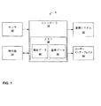
図1は、コンベアが清掃を必要とする時期を判断する保守システム8の例を示すブロック図である。保守システム8は、センサ10と、コントローラ12と、検出器14と、清掃システム22と、ユーザーインターフェイス24とを備える。コントローラ12はメモリ16を含み、メモリは、参照データモジュール18と検出データモジュール20とを含む。
FIG. 1 is a block diagram illustrating an example of a maintenance system 8 that determines when a conveyor needs cleaning. The maintenance system 8 includes a sensor 10, a
いくつかの例において、センサ10は、コンベアの位置に関するデータを収集する。例えば、センサ10は、電磁場または静電場を発して、場におけるコンベアシステムの特定の部品のセンサ10に対する近接度の変化を感知する、誘電性または容量性センサを備えることができる。別の例において、センサ10は、コンベアの移動または回転を表すことができるコンベア表面の反射率の変化を検出する光センサ例えば光学遮断器(opto-interrupter)を備えることができる。その代わりにまたはそれに加えて、センサ10は、時間の経過に関するデータを収集できる。例えば、センサ10は、時計またはタイマーなど計時装置を備えることができる。 In some examples, the sensor 10 collects data regarding the position of the conveyor. For example, the sensor 10 can comprise a dielectric or capacitive sensor that emits an electromagnetic or electrostatic field to sense a change in proximity of the particular component of the conveyor system in the field to the sensor 10. In another example, the sensor 10 can include an optical sensor, such as an opto-interrupter, that detects a change in the reflectivity of the conveyor surface that can represent movement or rotation of the conveyor. Alternatively or additionally, the sensor 10 can collect data regarding the passage of time. For example, the sensor 10 can include a time measuring device such as a clock or a timer.
コントローラ12は、センサ10からデータを受信し、データを分析し、分析に基づいて光学データを収集するよう検出器14に命令する。コントローラ12は、センサ10からデータを受信して、コンベア上の汚れの量及び(または)組成に関する光学データを収集することが望ましい位置まで回転したまたは望ましい距離を回転したと判断できる。例えば、コントローラ12は、検出器に対して特定の位置までコンベアが回転したという判断に基づいて、光学データを収集するよう検出器14に命令できる。別の例において、コントローラ12は、設定された時間量が経過したことを示すデータをセンサ10から受信し、設定された時間量が経過したときデータを収集するよう検出器14に命令できる。
The
検出器14は、いくつかの例において、コンベアの特定の部分に関する赤、緑、青の相対的量に関する光学データを収集する赤/緑/青(RGB)検出器である。このデータは、コンベア上の汚れの量及び(または)組成を表すことができる。他の例において、検出器14を、最小(例えば黒)と最大(例えば、白)との間の所定の範囲内で表されるコンベアの特定の部分の光強度に関する光学データを収集するグレースケールセンサとすることができる。例えば、グレースケールは、4ビットグレースケールの場合0=黒から256=白までの範囲である。グレースケールの示度は、コンベア上の汚れの量及び(または)組成を表すことができる。他の例において、検出器14は、コンベアの特定の部分の画像の形式で光学データを捕捉するカメラである。
The
どの特定のタイプの検出器14を採用するかに関係なく、コントローラ12は、検出器14から光学データを受信して、光学データの分析に基づいてコンベアが清掃を必要とするか否かを判断する。コントローラ12は、検出器14から受信した光学データを基準データ18と比較できる。基準データ18は、例えば、コンベアが「きれい」だった時点で取得した光学データを含むことができる。より明確には、コントローラ12は、光学データから光学パラメータに関する基準値(metric)を生成して、これを基準データ18から得られる対応する基準値と比較できる。基準値同士の間の差が閾値を満たす場合、コントローラ12は、コンベアが清掃を必要とすると判断できる。
Regardless of which particular type of
いくつかの例において、コントローラ12は、光学データの中の異常を排除するためにコンベアの複数の部分から収集された光学データから平均値を判断し、平均値を用いて、コンベアが清掃を必要とするか否かを判断できる。例えば、コントローラ12は、選択された周期で及び(または)設定された時間量の間に、コンベア上の汚れの量を表す複数の光学データサンプルを捕捉するよう検出器14に命令できる。コントローラ12は、検出データ20として複数の光学データサンプルを記憶できる。特定の数のサンプルが収集され、かつ(または)設定された時間量が経過したら、コントローラ12は検出データ20にアクセスして、各サンプルから光学データについて1つまたはそれ以上の基準値を生成できる。コントローラ12は、特定の数のサンプルから基準値の平均値を判断し、平均値を基準データ18と比較することによって平均値に基づきコンベアが清掃を必要とするか否かを判断できる。別の例において、コントローラ12は、光学データサンプルの最大値、最小値、平均値及び(または)値の範囲を判断して、これらの値を様々に使用して、コンベア上の汚れの量を数量化できる。本明細書においては光学的検出を用いたコンベア上の汚れの量を数量化する特定の例を説明するが、本発明はこの点に関して限定されず、光学データサンプルを収集し数量化するための多数のやり方が技術上知られていることが、当業者には容易に分かるだろう。
In some examples, the
コンベアが清掃を必要とするとコントローラ12が判断した場合、コントローラ12は、清掃システム22を起動して、自動的に清掃サイクルを開始できる。清掃システム22は、潤滑装置またはコンベアを効果的に清掃できるその他の装置を備えることができる。清掃システム22は完全にまたは部分的に自動的にすることができる。
If the
その代わりにまたはそれに加えて、コントローラ12は、電子通信を発して、コンベアが清掃を必要とすることを使用者に警告できる(または、清掃サイクルが自動的に開始されたことを使用者に警告できる)。例えば、コントローラ12は、ユーザーインターフェイス24に局部的な視覚的または聴覚的警告を発するか、またはeメール、音声メール、テキストメッセージ、呼び出しなどを介してネットワークコンピュータ、携帯電話、携帯情報端末、ポケットベルまたはその他の通信装置などの遠隔配置の外部装置へ送られる電子通信を発することができる。
Alternatively or additionally, the
図2は、コンベアシステム26の例及び保守システム8の例(図1)を示す概略図である。この例において、コンベアシステム26は、コンベア28と、駆動軸30とを含む。駆動軸30は、コンベア28内部に配置され、コンベア28を回転させる。しかし、他の形式のコンベアシステムを使用できること、及び本発明はこの点に関して限定されないことが分かるはずである。
FIG. 2 is a schematic diagram illustrating an example of the conveyor system 26 and an example of the maintenance system 8 (FIG. 1). In this example, the conveyor system 26 includes a
いくつかの例において、センサ10は、検出器14がコンベア上の汚れの量を表す光学データを捕捉するのに適切な位置にコンベアがあるか否かを表すデータを捕捉する。この場合、センサ10は、コンベアシステム26に対して、現在のコンベア位置に関するデータを検出できるような位置に定められる。コントローラ12は、コンベア自体に関して捕捉されたセンサデータから現在のコンベア位置を判断できる。または、コントローラ12は、駆動軸30などコンベアシステムの1つまたはそれ以上の部分に関して捕捉されたセンサデータから現在のコンベア位置を推測できる。センサ10からのデータが、コンベアが適切な位置にあることを示す場合、コントローラ12は、コンベア上の汚れの量を表す光学データを捕捉するよう、検出器14に命令できる。
In some examples, the sensor 10 captures data indicating whether the conveyor is in a proper position for the
センサ10がコンベア位置を表すデータを捕捉する例において、センサ10として、誘電性センサ、容量性センサ、光学遮断器などの光センサ(コンベア28によって光線が遮断または検出されたとき検出する)、マーカーまたはコンベア28の物理的特性を検出する光センサ、コンベア28のある部分またはコンベア28に配置されたまたは接続されたマーカーとの物理的接触によって誘発される物理的センサ、またはコンベアの位置を検出できる他のセンサが考えられる。
In an example in which the sensor 10 captures data representing the conveyor position, the sensor 10 includes an optical sensor such as a dielectric sensor, a capacitive sensor, or an optical breaker (detected when light is blocked or detected by the conveyor 28), a marker Or a light sensor that detects physical properties of the
センサ10が誘電性、容量性または磁気センサである場合、駆動軸30の特定の部分に、センサ10によって生成される電磁場または静電場を変化させる物体32を備えることができる。これによって、センサ10は、物体32を備える駆動軸30の特定の部分がセンサ10に近接した位置まで回転したとき場の変化を感知できる。場の変化は、コンベア28が特定の量を回転したことを表すことができ、コントローラ12は、コンベア28が特定の量を回転したときに、コンベア上の汚れの量を表す光学データを収集するよう検出器14に命令できる。いくつかの例において、駆動軸30の複数の部分が物体32を備えることができ、コントローラ12は、駆動軸30の1回転に複数回、光学データを収集するよう検出器14に命令できる。
If the sensor 10 is a dielectric, capacitive or magnetic sensor, certain portions of the
他の例において、コンベア位置を感知するのではなくまたはそれに加えて、センサ10は、時計またはタイマーなど計時装置である。 In other examples, rather than sensing or in addition to the conveyor position, the sensor 10 is a timing device such as a clock or timer.
コントローラ12は、センサ10によって収集されたデータを受信し、これを分析して、検出器14がコンベア上の汚れの量を表す光学データ収集するのに適切な位置にコンベアがあるか否かを判断する。例えば、コントローラ12は、物体32がセンサ10に近接する位置まで回転したことを示すデータをセンサ10から受信できる。他の例において、コントローラ12は、コンベアが適切な位置にあることを示すデータをセンサ10から受信できる。コントローラ12は、その後、コンベア28の特定の部分、例えばリンク同士の間の開口が検出器14に近接する位置まで回転したことにより、コンベア28から光学データを収集するよう検出器14に命令できる。他の例において、コレクタ12は、特定の時間量を経過したことにより、コンベア28から光学データを収集するよう検出器14に命令できる。
The
図2に示すように、検出器14はセンサ10の下方に配置される。ただし、他の例において、検出器14は、センサ10の上方、センサ10とは反対のコンベアシステム26の側、または検出器14がコンベア28から光学データを収集できるようにする任意の位置に配置できる。他の例において、検出器14及びセンサ10を同一のハウジング内に収容できる。
As shown in FIG. 2, the
図1に関連して論じたように、いくつかの例において、検出器14は、RGB検出器を備えることができる。RGB検出器は、赤、緑及び青フィルタに結合されたフォトダイオードすなわち光を電流または電圧に変換する回路要素を備える。赤、緑及び青フィルタは、フォトダイオードが、特定のデータサンプル内例えばコンベア28の特定の部分内における赤、緑及び青の量及び分布に基づいてデータを生成できるようにする。コンベア28の特定の部分における赤、緑及び青の量及び分布は、コンベア28上の汚れの量を表すことができる。例えば、コンベア28の特定の部分内における赤、緑及び(または)青の量の増大は、コンベア28上の汚れの量の増大を表すことができる。特定の閾値を上回る増大は、コンベア28が清掃を必要とすることを表すことができる。
As discussed in connection with FIG. 1, in some examples,
RGB検出器14は、コンベア28の特定の部分例えばコンベア28の2つのリンクの間から、コンベアの特定の部分の赤、緑及び青色の組成に関する光学データを収集し、光学データをコントローラ12と互換性のある形式(例えば、コントローラ12が電気入力を要求する場合には電流または電圧)に変換する。コントローラ12は、光学データを受信し、比較のために基準データ18にアクセスできる。基準データ18は、コンベア28がきれいであると(主観的にまたは客観的に)判断されたときにRGB検出器14によって収集されたデータを含むことができる。コントローラ12は、収集データと基準データ18との比較に基づく基準値(例えば、基準データ18と比較した場合のコンベア28の特定の部分において検出された赤、緑及び(または)青の量の増大率)を判断できる。基準値が特定の閾値例えば赤、緑及び(または)青の量の50パーセントの増大を超えると、コントローラ12は、コンベア28が清掃を必要とすると判断できる。
The
他の例において、コントローラ12は、複数のデータ収集イベントに関してRGB検出器14からデータセットを受信し、データセットを検出データ20の中に記憶する。複数のデータセットの各々を記憶した後、コントローラ12は、データ収集カウンタを増加できる。データ収集カウンタが特定の閾値、例えば4データ収集事象(または他の設定された回数)に達したとき、コントローラ12は、検出データ20のデータにアクセスし、各データセットについて基準値を判断できる。コントローラ12は、その後、基準値の平均値を判断し、平均値を、基準データ18の中に記憶されたデータと比較して、基準値が特定の閾値を上回ってコンベア28が清掃を必要とするか否かを判断できる。コントローラ12は、それに加えてまたはその代わりに、技術上既知の他の方法で、光学データを分析して、コンベアが清掃を必要とするか否かを判断できる。
In another example, the
他の例において、検出器14は、特定サンプル内例えばコンベア28の特定の部分内の光強度の分布に基づくデータを収集するグレースケール検出器(例えば、フォトダイオードまたはその他の光学的検出器)を備えることができる。RBG検出器14と同様、グレースケール検出器14は、コンベア28の上の汚れの量を表すデータを生成できる。コントローラ12は、基準データ18の中に含まれるグレースケールデータをグレースケール検出器14から受信したデータと比較することによって、コンベア28が清掃を必要とするか否かを判断できる。
In other examples, the
他の例において、検出器14は、コンベア28の特定の部分の画像を撮るカメラなど画像捕捉装置を備えることができる。コントローラ12は、検出器14から画像を受信し、画像を基準データ18に記憶された基準画像と比較できる。例えば、コントローラ12は、各ピクセルの色組成及び(または)強度を表す画像の各ピクセルの基準値を判断できる。コントローラ12は、基準画像の各ピルセルの対応する基準値を判断し、画像の各ピクセルからの基準値を基準画像の各ピクセルの基準値と比較して、コンベア28の特定の部分が色または強度の増大を示すか否かを判断できる。色または強度の増大は、コンベア28上の汚れの量の増大を表すことができる。コントローラ12は、画像と基準画像との比較に基づいてコンベア28が清掃を必要とするか否かを判断できる。
In other examples, the
コンベア28が清掃を必要とするとコントローラ12が判断する場合、コントローラ12は、使用者例えばオペレータ、工場長、保守職員に警告を発することができる。使用者は、警告に反応して、コンベア28の清掃を開始できる。その代わりにまたはそれに加えて、コントローラ12は、コンベア28が清掃を必要とするとコントローラ12が判断する場合、清掃システム22を自動的に起動できる。清掃システム22は、いくつかの例において、コンベアシステム26の1つまたはそれ以上の部品に湿式または乾式潤滑を与えて、部品間の摩擦を軽減し、コンベア上の汚れの量を減少しかつ(または)コンベアシステム26の効率を上げる潤滑装置である。
If the
図3は、コンベア28(図2)が清掃を必要とする時期をコントローラ12が判断するプロセスの例を示す流れ図である。コントローラ12は、センサ10によって収集されたデータを受信する(34)。例えば、コントローラ12は、コンベア28の現在位置に関するデータを受信できる。このデータから、コントローラ12は、コンベアがコンベア上の汚れの量を表す光学データを捕捉するのに適切な位置にあるか否かを判断できる。コントローラ12は、その代わりにまたはそれに加えて、設定された時間量を経過したことを示すデータをセンサ10から受信できる。コントローラ12は、センサ10から受信したデータに基づいて光学データを収集するよう検出器14に命令するべきか否かを判断する(36)。コントローラ12が、光学データを捕捉するのに適切な時点であると判断する場合、コントローラ12は、コンベア28から光学データを収集するよう検出器14に命令する(38)。検出器14はこの時点で光学データを収集すべきでないとコントローラ12が判断する場合、コントローラ12は、引き続き、センサ10を監視し、センサ10からのデータを受信する(34)。
FIG. 3 is a flowchart illustrating an example of a process in which the
コントローラ12は、検出器14によって収集された光学データを受信する(40)。コントローラ12は、光学データを基準データ18と比較できる(42)。基準データは、コンベア28がきれいであると判断されたときに収集されたデータを含むことができる。コントローラ12は、検出器14によって収集された光学データと基準データ18との比較に基づいて基準値を判断する(44)。コントローラ12は、基準値を特定の閾値と比較して、基準値が特定の閾値を上回るか否かを判断する(46)。基準値が特定の閾値を上回らないとコントローラ12が判断した場合、コントローラ12は、コンベアが清掃の必要がないと判断し、引き続き、センサ10を監視して、センサからデータを受信する(34)。コンベアが清掃を必要とするとコントローラ12が判断した場合、コントローラ12は、清掃システムを起動してコンベア28を清掃すること、及び(または)コンベア28が清掃を必要とすることを表す警告を使用者に発することができる(50)。
他の例において、コントローラ12は、検出器14によって収集された光学データを受信し、検出データモジュール20にデータを記憶して、検出データモジュール20の光学データの記憶に基づいてデータ収集カウンタを増加させる。コントローラ12は、データ収集カウンタを監視して、データ収集カウンタが特定の閾値を上回ったか否かを判断する。例えば、充分なデータセットが記憶されたかまたは充分なデータが収集されたか否かを判断する。データ収集カウンタが閾値を上回ったとコントローラ12が判断した場合、コントローラ12は、記憶されたデータセットの各々について光学パラメータの基準値を判断し、基準値の平均値を判断し、平均値を基準データ18と比較して、平均値と基準データ18との間の差が特定の閾値、例えば60%の強度の増大を上回るか否かを判断して、コンベア20が清掃を必要とするか否かを判断できる。
In another example, the
いくつかの例において、使用者または整備技師が閾値設定及び(または)「きれいな」基準設定を調節して、保守システム8を様々なコンベアの応用及び環境に適合できる。 In some examples, a user or mechanic can adjust the threshold settings and / or “clean” reference settings to adapt the maintenance system 8 to various conveyor applications and environments.
図4Aは、コンベア28がコンベアシステム(図2)の一部品として回転するとき駆動軸30に直接当接するコンベア28の内面の一部を示す概略図である。図4Aは、コンベア28の3つのリンク52の内面を示し、各々、内側エリア54と外側エリア56とを備える。内側エリア54及び(または)外側エリア56の表面の汚れの量は、コンベア28の内面のほとんどまたは全ての部分における汚れの量を表すことができる。従って、いくつかの例において、検出器14は、コンベア28が清掃を必要とするか否かを判断するために、内側エリア54及び(または)外側エリア56から光学データを収集するように配置される。
FIG. 4A is a schematic diagram showing a portion of the inner surface of the
いくつかの例において、検出器14は、コンベア28の内面に近接して配置され、内側エリア及び(または)外側エリア56から光学データを収集できる。検出器14がコンベア28の内面に近接して配置される例において、検出器14によって収集されたデータが検出器14の表面に蓄積するほこりまたはゴミの影響を受けないようにするために、検出器14は、清掃器具または装置を備えることができる。その代わりにまたはそれに加えて、使用者が、定期的に検出器14を清掃できる。
In some examples, the
図4Bは、コンベアシステム26によって輸送される積荷に直接当接しかつ駆動軸30には直接当接しない、コンベア28の外面の一部を示す概略図である。図4Bはコンベア28のリンク52の外面を示す。リンク52同士の間の開口58は、リンク52が駆動軸30の周りを回転しているときに現れる。
FIG. 4B is a schematic diagram illustrating a portion of the outer surface of the
いくつかの例において、センサ10は開口58を感知でき、コントローラ12は、開口58の感知に基づいて、コンベア28が特定の位置まで回転したことまたは特定の距離を回転したと、例えば丸1回転したと判断できる。例えば、コンベア28が特定の数の開口、例えば100個の開口を備える場合、コントローラ12は、センサ10が特定の数の開口(この例においては100個の開口)を感知したという判断に基づいて、コンベア28が丸1回転したと判断できる。
In some examples, the sensor 10 can sense the
いくつかの例において、センサ10は、図2に関連して論じたように、誘電性または容量性センサを備えることができる。他の例において、センサ10は、例えば、オプトインタラクタなど、コンベア28のある部分の反射率を感知する光センサを備えることができる。コントローラ12は、コンベア28のその部分の反射率の変化がコンベア28の移動または回転を表すと判断できる。例えば、開口58はリンク52の外面と異なる反射率を持つことができるので、センサ10は、コンベア28の外面の外縁、例えば外縁60の反射率を感知するように配置できる。コントローラ12は、外縁がセンサ10を通過して回転するときコンベア28の外面の外縁の反射率の変化に基づいて開口58が特定の回数センサ10を通過して回転したと判断できる。従って、コントローラ12は、コンベア28が特定の位置まで回転したまたは特定の距離を回転したと判断できる。その代わりにまたはそれに加えて、センサ10は、駆動軸30のある部分の反射率を感知して、コンベア28が特定の位置まで回転したかまたは特定の距離を回転したか否かを判断できる。
In some examples, the sensor 10 can comprise a dielectric or capacitive sensor, as discussed in connection with FIG. In other examples, the sensor 10 may comprise an optical sensor that senses the reflectance of certain portions of the
その代わりにまたはそれに加えて、作動時に回転または移動するコンベアシステム26の一部、例えば駆動軸30またはリンク52の一部に反射性物質またはその他の可視マーカーを適用できる。センサ10は、反射性物質またはその他の可視マーカーの存在を感知するように配置できる。コントローラ12は、反射物質またはその他の可視マーカーの感知に基づいて、コンベア28が特定の位置まで回転したまたは特定の距離を回転したと判断できる。
Alternatively or additionally, reflective material or other visible markers can be applied to a portion of the conveyor system 26 that rotates or moves during operation, such as the
または、センサ10は、リンク52の間の開口58の存在を検出でき、この検出は、コンベア上の汚れの量を表す光学データの捕捉を誘発できる。図4A及び4Bに示すリンク装置などいくつかのコンベアシステムにおいて、汚れは、開口においてリンクの縁に集まる傾向がある。開口58は、コンベア28の外面または内面よりも早く汚れを蓄積する可能性があるので、開口58に関して捕捉された光学データは、コンベア28が清掃を必要とする時期をより正確に表すことができる。従って、いくつかの例において、コンベア上の汚れの量を表す光学データは、コンベアが駆動軸の周りを回転するとき、リンク同士の間の開口が比較的大きく露出されるときに関して捕捉できる。コントローラ12は、開口58から検出器14が収集した光学データを、開口58がきれいであると判断されたとき、収集され記憶された基準データ18と比較できる。その代わりにまたはそれに加えて、検出器14は、光学データを基準データ18と比較する代わりに、開口58から収集された光学データをコンベア28の外面または内面から収集された光学データと比較して、コンベア28が清掃を必要とするか否かを判断できる。
Alternatively, the sensor 10 can detect the presence of an
その代わりにまたはそれに加えて、コンベアの位置を感知する代わりに、センサ10は、時計またはタイマーなど計時装置を備えることができる。コントローラ12は、時間経過に関するデータをセンサ10から受信できる。コントローラ12はその後、特定の時間量、例えば1分が経過したことを判断でき、それにより検出器14がコンベア28から光学データを収集できると判断できる。
Alternatively or in addition, instead of sensing the position of the conveyor, the sensor 10 may comprise a timing device such as a clock or timer. The
本発明の様々な例について説明した。これらの例及び他の例は、以下の特許請求の範囲に属する。 Various examples of the invention have been described. These and other examples are within the scope of the following claims.
Claims (10)
前記コンベアが前記特定の物理的位置にあるとの判断に基づいて、前記コントローラが前記コンベアから少なくとも1つの光学パラメータに関するデータを収集するステップであって、前記少なくとも1つの光学パラメータは、前記コンベアの部分の少なくとも1つの色組成、又は前記コンベアの部分のグレースケール強度を含む、収集するステップと、
前記収集したデータを前記少なくとも1つの光学パラメータに関する基準データと比較するステップと、
前記コントローラが、少なくとも2組のデータに関する基準値同士の間の差が閾値を満たす場合において前記コンベアが清掃を必要とすると判断するという比較に基づいて前記コンベアが清掃を必要とするか否かを判断するステップと、
前記コンベアが清掃を必要とするという判断に基づいて清掃システムを起動するステップまたは使用者に警告を発するステップのうちの少なくとも1つを含み、
前記清掃システムは、コンベアの一つ以上の部品に湿式または乾式潤滑を与える潤滑装置である、方法。 A controller determining that the conveyor is in a particular physical position by sensing an opening between the two links of the conveyor ;
Based on the determination that the con bare is in said specified physical location, said controller comprising: collecting data relating to at least one optical parameter from said conveyor, said at least one optical parameter, the conveyor Collecting at least one color composition of a portion of the portion, or grayscale intensity of the portion of the conveyor;
Comparing the collected data with reference data for the at least one optical parameter;
Whether the conveyor needs cleaning based on a comparison that the controller determines that the conveyor needs cleaning when the difference between the reference values for at least two sets of data meets a threshold. A step of judging;
Wherein at least one of the steps of issuing a warning to the steps or the user starts the cleaning system based on a determination that the configuration bare requires cleaning,
The method wherein the cleaning system is a lubrication device that provides wet or dry lubrication to one or more parts of a conveyor.
前記コントローラがデータを収集するステップが、前記コントローラが前記特定の時間量が経過したという判断に基づいてデータを収集するステップを含む、
請求項1に記載の方法。 And further comprising the step of the controller determining that a certain amount of time has elapsed,
Collecting data by the controller includes collecting data based on a determination that the controller has passed the particular amount of time;
The method of claim 1.
前記コンベアの2つのリンク同士の間の開口を感知することによって前記コンベアが前記特定の物理的位置にあると前記コントローラが判断するステップが、
前記コンベアの2つのリンク同士の間の開口を感知するステップと、
センサが前記特定の数の開口を感知したという判断に基づいて、前記コンベアが特定の物理的位置にあると前記コントローラが判断するステップとを含む、
請求項1に記載の方法。 The conveyor comprises a certain number of openings;
Determining by the controller that the conveyor is in the particular physical position by sensing an opening between two links of the conveyor ;
Sensing a opening between the two links between the Con bare,
The controller determining that the conveyor is in a particular physical position based on a determination that a sensor has sensed the particular number of openings .
The method of claim 1.
請求項1に記載の方法。 Comprising the step of determining that the con bare is in said specified physical location by sensing the opening between the two links between the conveyor, it determines that the configuration bare is rotated a specific distance ,
The method of claim 1.
データの収集に基づいてデータ収集カウンタを増加させるステップと、
前記データ収集カウンタが特定の閾値に達したと判断するステップと、
前記データ収集カウンタが前記特定の閾値に達したという判断に基づいて、少なくとも2組のデータに関する基準値に基づく平均値、最大値、最小値または範囲値のうちの少なくとも1つを判断するステップと、
を含み、
前記基準値に基づいて前記コントローラが清掃を必要とすると判断するステップが、前記平均値、最大値、最小値または範囲値のうちの少なくとも1つに基づいて、前記コントローラが清掃を必要とすると判断するステップを含む、
請求項1に記載の方法。 further,
Increasing the data collection counter based on the data collection;
Determining that the data collection counter has reached a particular threshold;
Determining at least one of an average value, a maximum value, a minimum value, or a range value based on a reference value for at least two sets of data based on a determination that the data collection counter has reached the specific threshold; ,
Including
The step of determining that the controller needs cleaning based on the reference value determines that the controller needs cleaning based on at least one of the average value, the maximum value, the minimum value, or the range value. Including the step of
The method of claim 1.
前記少なくとも1つの光学パラメータに関する基準データを記憶するメモリと、
前記コンベアの2つのリンク同士の間の開口を感知することによって前記コンベアが前記特定の物理的位置にあるときをコントローラが判断し、前記コントローラが前記光学データを前記基準データと比較し、かつ前記コントローラが、少なくとも2組のデータに関する基準値同士の間の差が閾値を満たす場合において前記コンベアが清掃を必要とすると判断するという比較に基づいて前記コンベアが清掃を必要とするか否かを判断するコントローラと、
コンベアの一つ以上の部品に湿式または乾式潤滑を与える潤滑装置である清掃システムと、を備える、
システム。 A detector that collects optical data relating to at least one optical parameter from a conveyor based on a determination that the conveyor is in a particular physical position, wherein the at least one optical parameter is at least a portion of the conveyor A detector comprising one color composition, or grayscale intensity of a portion of the conveyor;
A memory for storing reference data relating to the at least one optical parameter;
The conveyor controller determines when in the specific physical location by sensing the opening between the two links between said conveyor, said controller comparing the optical data and the reference data, and wherein controller, whether the con bare on the basis of the comparison that determines that the conveyor when the difference between the adjacent reference values for at least two sets of data satisfies a threshold requires cleaning requires cleaning A controller to judge,
A cleaning system that is a lubrication device that provides wet or dry lubrication to one or more parts of the conveyor;
system.
前記コントローラは、前記センサデータに基づいて、前記コンベアが前記特定の物理的位置にあるときを判断する、
請求項6に記載のシステム。 And a sensor for collecting sensor data relating to the physical position of the conveyor,
The controller determines when the conveyor is at the specific physical position based on the sensor data.
The system according to claim 6.
請求項7に記載のシステム。 The sensor comprises at least one of a dielectric sensor, a capacitive sensor, an optical sensor or a time sensor;
The system according to claim 7.
請求項7に記載のシステム。 The detector comprises one of an RGB sensor or a grayscale sensor;
The system according to claim 7.
前記少なくとも1つの光学パラメータに関する基準データを記憶するメモリと、
前記コンベアの物理的位置に関するデータを収集するように構成されたセンサと、
コントローラが、前記センサによって収集されたデータに基づいて前記コンベアが前記特定の物理的位置にあると判断し、前記コンベアが前記特定の物理的位置にあるとの判断に基づいて前記光学データを収集する検出器を前記コントローラが制御し、前記コントローラが、前記収集した光学データを前記基準データと比較し、かつその比較に基づいて前記コンベアが清掃を必要とするか否かを判断するコントローラと、
コンベアの一つ以上の部品に湿式または乾式潤滑を与える潤滑装置である清掃システムと、を備える、
システム。 A detector configured to collect optical data relating to at least one optical parameter from the conveyor based on a determination that the conveyor is in a particular physical position;
A memory for storing reference data relating to the at least one optical parameter;
A sensor configured to collect data relating to the physical position of the conveyor;
Controller determines that the configuration bare on the basis of the data collected by the sensor is the specific physical location, the optical data based on a determination that the configuration bare is in said specified physical location controlled by the said controller a detector for collecting, said controller optical data the collected compared with the reference data, and the con bare determines whether require cleaning on the basis of the comparison A controller,
A cleaning system that is a lubrication device that provides wet or dry lubrication to one or more parts of the conveyor;
system.
Applications Claiming Priority (3)
| Application Number | Priority Date | Filing Date | Title |
|---|---|---|---|
| US12/696,439 US8141695B2 (en) | 2010-01-29 | 2010-01-29 | Clean conveyor sensing system |
| US12/696,439 | 2010-01-29 | ||
| PCT/IB2011/050328 WO2011092629A2 (en) | 2010-01-29 | 2011-01-25 | Clean conveyor sensing system |
Publications (3)
| Publication Number | Publication Date |
|---|---|
| JP2013518012A JP2013518012A (en) | 2013-05-20 |
| JP2013518012A5 JP2013518012A5 (en) | 2014-03-13 |
| JP5912085B2 true JP5912085B2 (en) | 2016-04-27 |
Family
ID=44319917
Family Applications (1)
| Application Number | Title | Priority Date | Filing Date |
|---|---|---|---|
| JP2012550543A Active JP5912085B2 (en) | 2010-01-29 | 2011-01-25 | Clean conveyor sensing system |
Country Status (5)
| Country | Link |
|---|---|
| US (1) | US8141695B2 (en) |
| EP (1) | EP2528848B1 (en) |
| JP (1) | JP5912085B2 (en) |
| ES (1) | ES2709149T3 (en) |
| WO (1) | WO2011092629A2 (en) |
Families Citing this family (64)
| Publication number | Priority date | Publication date | Assignee | Title |
|---|---|---|---|---|
| DE102010028769A1 (en) | 2010-05-07 | 2011-11-10 | Pvt Probenverteiltechnik Gmbh | System for transporting containers between different stations and container carriers |
| EP2589966A1 (en) | 2011-11-04 | 2013-05-08 | Roche Diagnostics GmbH | Laboratory sample distribution system and corresponding method of operation |
| EP2589968A1 (en) | 2011-11-04 | 2013-05-08 | Roche Diagnostics GmbH | Laboratory sample distribution system, laboratory system and method of operating |
| EP2589967A1 (en) | 2011-11-04 | 2013-05-08 | Roche Diagnostics GmbH | Laboratory sample distribution system and corresponding method of operation |
| DE102012209779A1 (en) * | 2012-06-12 | 2013-12-12 | Osram Gmbh | Circuit for controlling semiconductor light emitting elements e.g. LEDs, of lamp, has electronic switches controlled by microcontroller, and semiconductor luminous elements switched in series in different combinations by switches |
| CN103335504A (en) * | 2013-05-31 | 2013-10-02 | 吉铨精密机械(苏州)有限公司 | Drying machine with synchronous warning function |
| DE102014202843B3 (en) | 2014-02-17 | 2014-11-06 | Roche Pvt Gmbh | Transport device, sample distribution system and laboratory automation system |
| DE102014202838B3 (en) | 2014-02-17 | 2014-11-06 | Roche Pvt Gmbh | Transport device, sample distribution system and laboratory automation system |
| EP2927168A1 (en) | 2014-03-31 | 2015-10-07 | Roche Diagniostics GmbH | Transport device, sample distribution system and laboratory automation system |
| EP2927625A1 (en) | 2014-03-31 | 2015-10-07 | Roche Diagniostics GmbH | Sample distribution system and laboratory automation system |
| EP2927163B1 (en) | 2014-03-31 | 2018-02-28 | Roche Diagnostics GmbH | Vertical conveyor, sample distribution system and laboratory automation system |
| EP2927167B1 (en) | 2014-03-31 | 2018-04-18 | F. Hoffmann-La Roche AG | Dispatch device, sample distribution system and laboratory automation system |
| EP2927695B1 (en) * | 2014-03-31 | 2018-08-22 | Roche Diagniostics GmbH | Sample distribution system and laboratory automation system |
| US20170010221A1 (en) * | 2014-04-22 | 2017-01-12 | Halliburton Energy Services, Inc. | Systems and Methods for Analyzing Contaminants in Flowing Bulk Powder Compositions |
| EP2957914B1 (en) | 2014-06-17 | 2018-01-03 | Roche Diagnostics GmbH | Laboratory sample distribution system and laboratory automation system |
| EP2977766A1 (en) | 2014-07-24 | 2016-01-27 | Roche Diagniostics GmbH | Laboratory sample distribution system and laboratory automation system |
| US9096392B1 (en) * | 2014-08-29 | 2015-08-04 | Sergio S. Barragan | Conveyor belt steam cleaning device |
| EP2995580A1 (en) | 2014-09-09 | 2016-03-16 | Roche Diagniostics GmbH | Laboratory sample distribution system and laboratory automation system |
| EP2995960B1 (en) | 2014-09-09 | 2020-07-15 | Roche Diagniostics GmbH | Laboratory sample distribution system and method for calibrating magnetic sensors |
| US9952242B2 (en) | 2014-09-12 | 2018-04-24 | Roche Diagnostics Operations, Inc. | Laboratory sample distribution system and laboratory automation system |
| EP2995958A1 (en) | 2014-09-15 | 2016-03-16 | Roche Diagniostics GmbH | Method of operating a laboratory sample distribution system, laboratory sample distribution system and laboratory automation system |
| EP3006943B1 (en) | 2014-10-07 | 2020-04-22 | Roche Diagniostics GmbH | Module for a laboratory sample distribution system, laboratory sample distribution system and laboratory automation system |
| CA3055593C (en) * | 2014-10-28 | 2021-11-23 | Halliburton Energy Serivces, Inc. | Identification of material type and condition in a dry bulk material storage bin |
| WO2016068863A1 (en) * | 2014-10-28 | 2016-05-06 | Halliburton Energy Services, Inc. | Pneumatic conveying system and method using optical flow characterization data |
| WO2016068868A1 (en) * | 2014-10-28 | 2016-05-06 | Halliburton Energy Services, Inc. | Identification of material type and condition in a dry bulk material hopper |
| EP3016116A1 (en) | 2014-11-03 | 2016-05-04 | Roche Diagniostics GmbH | Printed circuit board arrangement, coil for a laboratory sample distribution system, laboratory sample distribution system and laboratory automation system |
| EP3070479B1 (en) | 2015-03-16 | 2019-07-03 | Roche Diagniostics GmbH | Transport carrier, laboratory cargo distribution system and laboratory automation system |
| EP3073270B1 (en) | 2015-03-23 | 2019-05-29 | Roche Diagniostics GmbH | Laboratory sample distribution system and laboratory automation system |
| EP3095739A1 (en) | 2015-05-22 | 2016-11-23 | Roche Diagniostics GmbH | Method of operating a laboratory sample distribution system, laboratory sample distribution system and laboratory automation system |
| EP3096145B1 (en) | 2015-05-22 | 2019-09-04 | Roche Diagniostics GmbH | Method of operating a laboratory automation system and laboratory automation system |
| EP3096146A1 (en) | 2015-05-22 | 2016-11-23 | Roche Diagniostics GmbH | Method of operating a laboratory sample distribution system, laboratory sample distribution system and laboratory automation system |
| EP3112874A1 (en) | 2015-07-02 | 2017-01-04 | Roche Diagnostics GmbH | Storage module, method of operating a laboratory automation system and laboratory automation system |
| EP3121603A1 (en) | 2015-07-22 | 2017-01-25 | Roche Diagnostics GmbH | Sample container carrier, laboratory sample distribution system and laboratory automation system |
| EP3139175B1 (en) | 2015-09-01 | 2021-12-15 | Roche Diagnostics GmbH | Laboratory cargo distribution system, laboratory automation system and method of operating a laboratory cargo distribution system |
| EP3153867B1 (en) | 2015-10-06 | 2018-11-14 | Roche Diagniostics GmbH | Method of configuring a laboratory automation system, laboratory sample distribution system and laboratory automation system |
| EP3153866A1 (en) | 2015-10-06 | 2017-04-12 | Roche Diagnostics GmbH | Method of determining a handover position and laboratory automation system |
| EP3156352B1 (en) | 2015-10-13 | 2019-02-27 | Roche Diagniostics GmbH | Laboratory sample distribution system and laboratory automation system |
| EP3156353B1 (en) | 2015-10-14 | 2019-04-03 | Roche Diagniostics GmbH | Method of rotating a sample container carrier, laboratory sample distribution system and laboratory automation system |
| JP6306617B2 (en) * | 2016-01-05 | 2018-04-04 | ファナック株式会社 | Machine tool with chip discharge device |
| EP3211429A1 (en) | 2016-02-26 | 2017-08-30 | Roche Diagnostics GmbH | Transport device having a tiled driving surface |
| EP3211430A1 (en) | 2016-02-26 | 2017-08-30 | Roche Diagnostics GmbH | Transport device with base plate modules |
| EP3211428A1 (en) | 2016-02-26 | 2017-08-30 | Roche Diagnostics GmbH | Transport device unit for a laboratory sample distribution system |
| NL2016340B1 (en) * | 2016-03-01 | 2017-09-11 | Rexnord Flattop Europe Bv | Method and system for transporting products. |
| WO2018160218A1 (en) | 2017-03-01 | 2018-09-07 | Rexnord Industries, Llc | Conveyor systems and methods |
| JP6708787B2 (en) | 2016-06-03 | 2020-06-10 | エフ.ホフマン−ラ ロシュ アーゲーF. Hoffmann−La Roche Aktiengesellschaft | Laboratory sample distribution system and laboratory automation system |
| EP3255519B1 (en) | 2016-06-09 | 2019-02-20 | Roche Diagniostics GmbH | Laboratory sample distribution system and method of operating a laboratory sample distribution system |
| EP3260867A1 (en) | 2016-06-21 | 2017-12-27 | Roche Diagnostics GmbH | Method of setting a handover position and laboratory automation system |
| JP6752350B2 (en) | 2016-08-04 | 2020-09-09 | エフ.ホフマン−ラ ロシュ アーゲーF. Hoffmann−La Roche Aktiengesellschaft | Laboratory sample distribution system and laboratory automation system |
| EP3330717B1 (en) | 2016-12-01 | 2022-04-06 | Roche Diagnostics GmbH | Laboratory sample distribution system and laboratory automation system |
| EP3343232B1 (en) | 2016-12-29 | 2021-09-15 | Roche Diagnostics GmbH | Laboratory sample distribution system and laboratory automation system |
| EP3355065B1 (en) | 2017-01-31 | 2021-08-18 | Roche Diagnostics GmbH | Laboratory sample distribution system and laboratory automation system |
| EP3357842B1 (en) | 2017-02-03 | 2022-03-23 | Roche Diagnostics GmbH | Laboratory automation system |
| EP3410123B1 (en) | 2017-06-02 | 2023-09-20 | Roche Diagnostics GmbH | Method of operating a laboratory sample distribution system, laboratory sample distribution system and laboratory automation system |
| EP3428653B1 (en) | 2017-07-13 | 2021-09-15 | Roche Diagnostics GmbH | Method of operating a laboratory sample distribution system, laboratory sample distribution system and laboratory automation system |
| EP3457144B1 (en) | 2017-09-13 | 2021-10-20 | Roche Diagnostics GmbH | Sample container carrier, laboratory sample distribution system and laboratory automation system |
| EP3456415B1 (en) | 2017-09-13 | 2021-10-20 | Roche Diagnostics GmbH | Sample container carrier, laboratory sample distribution system and laboratory automation system |
| TWI760594B (en) * | 2018-02-09 | 2022-04-11 | 荷蘭商耐克創新有限合夥公司 | Self-cleaning ring conveyor and system of applying material to a component on a self-cleaning ring conveyor |
| EP3540443B1 (en) | 2018-03-16 | 2023-08-30 | Roche Diagnostics GmbH | Laboratory system, laboratory sample distribution system and laboratory automation system |
| DE102018210670A1 (en) * | 2018-06-29 | 2020-01-02 | Krones Ag | Container treatment plant and control method |
| WO2020041796A1 (en) | 2018-08-24 | 2020-02-27 | Averon Us, Inc. | Methods, apparatuses, and computer program products for performing identification and authentication by linking mobile device biometric confirmation with third-party mobile device account association |
| US11747356B2 (en) | 2020-12-21 | 2023-09-05 | Roche Diagnostics Operations, Inc. | Support element for a modular transport plane, modular transport plane, and laboratory distribution system |
| CN113600525B (en) * | 2021-07-29 | 2022-09-16 | 河北白沙烟草有限责任公司保定卷烟厂 | Online cleaning device of copper bar chain based on intelligent recognition technology |
| JP7065238B1 (en) | 2021-08-03 | 2022-05-11 | 三ツ星ベルト株式会社 | Information management control method and management system for parts that make up the conveyor device |
| US20240082884A1 (en) * | 2022-04-25 | 2024-03-14 | John Bean Technologies Corporation | System and method for optimizing a cleaning session of a food processing system |
Family Cites Families (17)
| Publication number | Priority date | Publication date | Assignee | Title |
|---|---|---|---|---|
| JPH01320453A (en) | 1988-06-22 | 1989-12-26 | Sankyo Seiki Mfg Co Ltd | Appearance inspecting device |
| US5323230A (en) * | 1989-09-07 | 1994-06-21 | Fuji Photo Film Co., Ltd. | Method of measuring the reflection density of an image |
| US5110365A (en) * | 1990-12-03 | 1992-05-05 | The Babcock & Wilcox Company | Control of furnace cleaning for reflective ash using infrared imaging |
| US5363968A (en) * | 1991-08-23 | 1994-11-15 | Pfizer Inc. | Automatic blister inspection system |
| DE4332375A1 (en) * | 1993-09-23 | 1995-03-30 | Lang Apparatebau Gmbh | System and method for lubricating, cleaning and / or disinfecting conveyor belts or chains |
| JP3272201B2 (en) * | 1995-06-16 | 2002-04-08 | 濱田重工株式会社 | Conveyor belt surface cleaning device |
| JPH0912128A (en) * | 1995-06-30 | 1997-01-14 | Sumitomo Metal Ind Ltd | Belt scratch detecting device for belt conveyor device |
| US5849183A (en) * | 1996-08-30 | 1998-12-15 | Kabushiki Kaisha Syst | Filtration apparatus |
| JPH11132742A (en) * | 1997-10-28 | 1999-05-21 | Hitachi Techno Eng Co Ltd | Foreign matter detection method by image processing |
| AU771654B2 (en) | 1999-03-26 | 2004-04-01 | Eriez Manufacturing Co. | Non-continuous system for automatic self cleaning of permanent magnets or electromagnets |
| GB9919477D0 (en) * | 1999-08-17 | 1999-10-20 | Newman Paul B D | Substrate conveyors |
| US6302263B1 (en) * | 1999-10-08 | 2001-10-16 | Ecolab, Inc. | Apparatus and method for the controlled lubrication and cleaning of conveyors |
| JP3900772B2 (en) * | 2000-01-27 | 2007-04-04 | 松下電器産業株式会社 | Transport device |
| US6360874B1 (en) * | 2000-02-10 | 2002-03-26 | Ibp, Inc. | Automated conveyor cleaning system |
| GB2402119A (en) * | 2002-01-14 | 2004-12-01 | Univ Carnegie Mellon | Conveyor belt inspection system and method |
| JP4202707B2 (en) * | 2002-09-30 | 2008-12-24 | 富士フイルム株式会社 | Method for identifying periodic defect occurrence location and inspection system |
| JP5064004B2 (en) * | 2006-12-11 | 2012-10-31 | 池上通信機株式会社 | Powder removal device and tablet inspection device |
-
2010
- 2010-01-29 US US12/696,439 patent/US8141695B2/en active Active
-
2011
- 2011-01-25 ES ES11736687T patent/ES2709149T3/en active Active
- 2011-01-25 JP JP2012550543A patent/JP5912085B2/en active Active
- 2011-01-25 EP EP11736687.2A patent/EP2528848B1/en active Active
- 2011-01-25 WO PCT/IB2011/050328 patent/WO2011092629A2/en active Application Filing
Also Published As
| Publication number | Publication date |
|---|---|
| ES2709149T3 (en) | 2019-04-15 |
| EP2528848A2 (en) | 2012-12-05 |
| JP2013518012A (en) | 2013-05-20 |
| US20110186406A1 (en) | 2011-08-04 |
| EP2528848A4 (en) | 2017-11-22 |
| US8141695B2 (en) | 2012-03-27 |
| WO2011092629A3 (en) | 2011-11-17 |
| WO2011092629A2 (en) | 2011-08-04 |
| EP2528848B1 (en) | 2018-10-31 |
Similar Documents
| Publication | Publication Date | Title |
|---|---|---|
| JP5912085B2 (en) | Clean conveyor sensing system | |
| EP2819069A1 (en) | Electronic apparatus | |
| JP4601631B2 (en) | Electrical equipment management system | |
| US7253743B2 (en) | Techniques for identifying when to change an air filter | |
| JP5347845B2 (en) | Image processing program and image processing apparatus | |
| CN1882078B (en) | Image error detection device for monitoring camera | |
| KR102323044B1 (en) | System and method for anticipating low-speed bearing failure | |
| JP6438405B2 (en) | Manufacturing line monitoring device, manufacturing line monitoring program, manufacturing line monitoring method, manufacturing line monitoring system | |
| JP2008033532A (en) | Method and apparatus for detecting abnormality in equipment provided with movable part | |
| CN110608509A (en) | Filter screen filth blockage detection method and device, air conditioner and storage medium | |
| JP3827928B2 (en) | Monitoring system for machine parts | |
| CN109724776B (en) | Method and device for determining damage degree of grate bar of sintering machine trolley | |
| KR101961820B1 (en) | Maintenance forecast system for vision inspection apparatus | |
| JP6599416B2 (en) | Manufacturing line monitoring device, manufacturing line monitoring program, manufacturing line monitoring method, manufacturing line monitoring system | |
| CN104470845A (en) | Method and apparatus for monitoring the lubricant content of elevator ropes | |
| JP6870696B2 (en) | Dirt detector and air conditioning system | |
| WO2019208066A1 (en) | Image capture device and system | |
| CN116867607A (en) | Information processing apparatus | |
| CN111256182B (en) | Oil stain detection method applied to range hood | |
| CA3041760A1 (en) | Detection system | |
| JP5186973B2 (en) | Worker safety inspection device | |
| JP5795933B2 (en) | Optical information reader | |
| JPWO2019058590A1 (en) | Watching system, watching method, refrigerator, and communication terminal | |
| JP4980687B2 (en) | Monitoring system | |
| Jost et al. | Water streak detection with convolutional neural networks for scrubber dryers |
Legal Events
| Date | Code | Title | Description |
|---|---|---|---|
| A521 | Request for written amendment filed |
Free format text: JAPANESE INTERMEDIATE CODE: A523 Effective date: 20140124 |
|
| A621 | Written request for application examination |
Free format text: JAPANESE INTERMEDIATE CODE: A621 Effective date: 20140124 |
|
| A977 | Report on retrieval |
Free format text: JAPANESE INTERMEDIATE CODE: A971007 Effective date: 20141113 |
|
| A131 | Notification of reasons for refusal |
Free format text: JAPANESE INTERMEDIATE CODE: A131 Effective date: 20141125 |
|
| A521 | Request for written amendment filed |
Free format text: JAPANESE INTERMEDIATE CODE: A523 Effective date: 20150225 |
|
| A02 | Decision of refusal |
Free format text: JAPANESE INTERMEDIATE CODE: A02 Effective date: 20150804 |
|
| A521 | Request for written amendment filed |
Free format text: JAPANESE INTERMEDIATE CODE: A523 Effective date: 20151201 |
|
| A911 | Transfer to examiner for re-examination before appeal (zenchi) |
Free format text: JAPANESE INTERMEDIATE CODE: A911 Effective date: 20151209 |
|
| TRDD | Decision of grant or rejection written | ||
| A01 | Written decision to grant a patent or to grant a registration (utility model) |
Free format text: JAPANESE INTERMEDIATE CODE: A01 Effective date: 20160301 |
|
| A61 | First payment of annual fees (during grant procedure) |
Free format text: JAPANESE INTERMEDIATE CODE: A61 Effective date: 20160331 |
|
| R150 | Certificate of patent or registration of utility model |
Ref document number: 5912085 Country of ref document: JP Free format text: JAPANESE INTERMEDIATE CODE: R150 |
|
| R250 | Receipt of annual fees |
Free format text: JAPANESE INTERMEDIATE CODE: R250 |
|
| R250 | Receipt of annual fees |
Free format text: JAPANESE INTERMEDIATE CODE: R250 |
|
| R250 | Receipt of annual fees |
Free format text: JAPANESE INTERMEDIATE CODE: R250 |
|
| R250 | Receipt of annual fees |
Free format text: JAPANESE INTERMEDIATE CODE: R250 |
|
| R250 | Receipt of annual fees |
Free format text: JAPANESE INTERMEDIATE CODE: R250 |
|
| R250 | Receipt of annual fees |
Free format text: JAPANESE INTERMEDIATE CODE: R250 |