JP5910119B2 - headphone - Google Patents
headphone Download PDFInfo
- Publication number
- JP5910119B2 JP5910119B2 JP2012018276A JP2012018276A JP5910119B2 JP 5910119 B2 JP5910119 B2 JP 5910119B2 JP 2012018276 A JP2012018276 A JP 2012018276A JP 2012018276 A JP2012018276 A JP 2012018276A JP 5910119 B2 JP5910119 B2 JP 5910119B2
- Authority
- JP
- Japan
- Prior art keywords
- driver unit
- housing
- headphones
- wearer
- auricle
- Prior art date
- Legal status (The legal status is an assumption and is not a legal conclusion. Google has not performed a legal analysis and makes no representation as to the accuracy of the status listed.)
- Active
Links
Images


Classifications
-
- H—ELECTRICITY
- H04—ELECTRIC COMMUNICATION TECHNIQUE
- H04R—LOUDSPEAKERS, MICROPHONES, GRAMOPHONE PICK-UPS OR LIKE ACOUSTIC ELECTROMECHANICAL TRANSDUCERS; DEAF-AID SETS; PUBLIC ADDRESS SYSTEMS
- H04R1/00—Details of transducers, loudspeakers or microphones
- H04R1/10—Earpieces; Attachments therefor ; Earphones; Monophonic headphones
- H04R1/1091—Details not provided for in groups H04R1/1008 - H04R1/1083
-
- H—ELECTRICITY
- H04—ELECTRIC COMMUNICATION TECHNIQUE
- H04R—LOUDSPEAKERS, MICROPHONES, GRAMOPHONE PICK-UPS OR LIKE ACOUSTIC ELECTROMECHANICAL TRANSDUCERS; DEAF-AID SETS; PUBLIC ADDRESS SYSTEMS
- H04R1/00—Details of transducers, loudspeakers or microphones
- H04R1/10—Earpieces; Attachments therefor ; Earphones; Monophonic headphones
- H04R1/1058—Manufacture or assembly
- H04R1/1075—Mountings of transducers in earphones or headphones
-
- H—ELECTRICITY
- H04—ELECTRIC COMMUNICATION TECHNIQUE
- H04R—LOUDSPEAKERS, MICROPHONES, GRAMOPHONE PICK-UPS OR LIKE ACOUSTIC ELECTROMECHANICAL TRANSDUCERS; DEAF-AID SETS; PUBLIC ADDRESS SYSTEMS
- H04R1/00—Details of transducers, loudspeakers or microphones
- H04R1/10—Earpieces; Attachments therefor ; Earphones; Monophonic headphones
- H04R1/1008—Earpieces of the supra-aural or circum-aural type
-
- H—ELECTRICITY
- H04—ELECTRIC COMMUNICATION TECHNIQUE
- H04R—LOUDSPEAKERS, MICROPHONES, GRAMOPHONE PICK-UPS OR LIKE ACOUSTIC ELECTROMECHANICAL TRANSDUCERS; DEAF-AID SETS; PUBLIC ADDRESS SYSTEMS
- H04R1/00—Details of transducers, loudspeakers or microphones
- H04R1/10—Earpieces; Attachments therefor ; Earphones; Monophonic headphones
- H04R1/105—Earpiece supports, e.g. ear hooks
Description
本開示は、ヘッドホンに関する。詳しくは、装着時の音源位置を安定させることにより、低音域の再現性を高め、また装着性を高めた機構を有するヘッドホンに関する。 The present disclosure relates to headphones. More specifically, the present invention relates to headphones having a mechanism that improves the reproducibility of the low frequency range by stabilizing the position of the sound source when worn and improves the wearability.
従来のヘッドバンドを有するヘッドホンであって、装着者の耳全体を覆うヘッドホンは様々に開発されてきた。 Various headphones having a conventional headband and covering the entire ear of the wearer have been developed.
例えば、音源であるドライバユニットが装着者の側頭部と略平行に固定して配設されているヘッドホン、およびドライバユニットが装着者の側頭部に対して若干の傾斜を設けて固定されているヘッドホン等が挙げられる。 For example, a headphone in which a driver unit that is a sound source is fixed and arranged substantially parallel to a wearer's temporal region, and a driver unit is fixed with a slight inclination with respect to the wearer's temporal region. Headphones.
さらに、特許文献1には音響出力部が収納されるバックシェル、耳介に嵌合するイヤーホルダおよび音響出力部の放音面を覆うセパレータを備えるヘッドホンが記載されている。なお、特許文献1に記載のヘッドホンは、耳介に対する圧迫感や密着感に伴う苦痛や不快感などを生じさせることなく、長時間にわたって使用することができると記載されている(特許文献1の請求項1、段落0052および図1〜図3、図7参照)。
Furthermore,
従来のヘッドホンに比べて、低音域の再現性と装着時の快適性とをより一層向上したヘッドホンが求められていた。 Compared to conventional headphones, there has been a demand for headphones that further improve the reproducibility of the low frequency range and the comfort when worn.
従来のドライバユニットが固定されているヘッドホンを使用した場合、ドライバユニットの固定位置および固定角度、さらに装着者の耳介の形状に因っては、装着時にドライバユニットが耳介に対して離れてしまうことにより、音が小さい、低音が少ないと感じることがあった。特にオープンタイプのヘッドホンの場合、ドライバユニットと耳介とが離れていると、低音の再現性が乏しくなる傾向があった。また、装着時にドライバユニットが耳介に対して接触することにより、痛みの原因となることもあった。 When using a conventional headphone with a fixed driver unit, the driver unit may be separated from the pinna when worn, depending on the fixing position and angle of the driver unit and the shape of the pinna of the wearer. As a result, it sometimes felt that the sound was low and the bass was low. In particular, in the case of an open type headphone, if the driver unit and the auricle are separated, the reproducibility of the bass tends to be poor. Also, the driver unit may come into contact with the auricle when worn, causing pain.
さらに、特許文献1に記載のヘッドホンは、素材にも因るが、耳かけ型のイヤホンと同様に、耳介の裏側の頭頂部側および後頭部側に接触の力点が集中するので、長時間の使用によって接触部位で痛みを生じる可能性があった。
Furthermore, although the headphones described in
したがって、本開示が解決しようとする課題は、様々な装着者に対して音源の位置を安定させることにより高い低音域の再現性を確保することができ、装着時に耳介への痛みを軽減することもできる機構を有するヘッドホンを提供することである。 Therefore, the problem to be solved by the present disclosure is that the reproducibility of a high bass range can be ensured by stabilizing the position of the sound source for various wearers, and the pain to the auricle can be reduced at the time of wearing. It is to provide a headphone having a mechanism that can also.
上述の課題を解決するために、本開示は、一端開口部の周囲にイヤパッドが取り付けられた略円筒体のハウジングと、
可撓性を有し、孔のない膜状体により形成された筒状の弾性部材であって、一端開口部がハウジングの他端開口部に固定され、他端開口部の外側にドライバユニットが取り付けられた連結部材と
を備えるヘッドホンである。
In order to solve the above-described problem, the present disclosure includes a substantially cylindrical housing in which an ear pad is attached around one end opening;
A cylindrical elastic member formed of a flexible film-like body having no holes, one end opening is fixed to the other end opening of the housing, and the driver unit is outside the other end opening. It is a headphone provided with the attached connecting member .
本開示によると、ドライバユニットが可動であるので、耳介の形状が異なる様々な装着者に対して音源の位置を一定に位置決めすることにより、高い低音域の再現性を確保することができ、装着時にドライバユニットが耳介に接触しても、接触によって耳介に痛みを生じないヘッドホンを提供することができる。 According to the present disclosure, since the driver unit is movable, it is possible to ensure high bass reproducibility by positioning the sound source constant for various wearers with different pinna shapes, Even if the driver unit comes into contact with the pinna when worn, it is possible to provide a headphone that does not cause pain in the pinna due to the contact.
(ヘッドホンの基本的構造)
まず、図1を参照しつつ、ヘッドホン1の構成について説明する。図1は、本開示に係るヘッドホン1の外観構成を示す図である。なお、図1は説明の都合上、一部の部材を省略した状態で示している。なお、Lチャンネル側のハウジング5およびイヤパッド6もRチャンネル側と同様に構成されている。
(Basic structure of headphones)
First, the configuration of the
ヘッドホン1は、ヘッドバンド2、スライダ3、ハンガ4、ハウジング5、イヤパッド6およびハウジング5内に設けられたドライバユニット部7とから構成されている。
The
ヘッドバンド2は装着者の頭部に沿うように湾曲状に形成されており、装着状態において装着者の頭頂部に接することによりヘッドホン1全体を支持するものである。ヘッドバンド2はプラスチックなどの合成樹脂、金属などを用いて構成されており、所定の剛性および弾性を有することにより可撓性を備えている。これにより、装着時にはハウジング5およびイヤパッド6を装着者の側頭部方向に押圧してヘッドホン1の装着状態を維持することができる。なお、ヘッドバンド2の内面における装着者の頭頂部に当接する部分に緩衝材としてゴムなどを設けるようにしてもよい。さらに、ヘッドホン1の携帯時に中央で折り畳めるようにヒンジを備えるようにしてもよい。
The
スライダ3は、ヘッドバンド2の両端に設けられている。そして、スライダ3の一端部における接合部8には、ハンガ4が取り付けられている。ヘッドバンド2の両端に固定され、かつヘッドバンド2の中心軸線と一致する軸線を有して成る案内部材9に沿って、スライダ3が摺動可能に構成されている。スライダ3を案内部材9に沿って摺動させることにより、ハンガ4をヘッドバンド2に対して遠ざかるように、または近づくように移動させることができる。ヘッドホン1の装着時には、装着者の頭部の大きさや耳と頭頂部との距離などに合わせてスライダ3の位置を調整することにより、ハウジング5およびイヤパッド6を装着者の耳に対向する位置に合わせる事ができる。これにより、装着者は自らの身体的特徴や嗜好に応じた装着感を得ることができる。一方、ヘッドホン1を使用しない場合には、スライダ3を縮めた状態にすることにより、保管スペースを節約することができる。
The slider 3 is provided at both ends of the
ハンガ4はスライダ3の先端に接合部8を介して設けられており、ハウジング5を回動自在に支持するものである。なお、接合部8はハンガ4を、固定的に保持しても良く、ヘッドバンド2および案内部材9の軸線の周りを回動することができるように保持しても良い。ハンガ4は、例えば、一対の先端からそれぞれ内向きに突出する支持ピン(図示せず。)で軸支することによりハウジング5を回動自在に支持する。これにより、ヘッドホン1の装着時においては、装着者の耳および側頭部の形状に合わせてハウジング5の向きが変わるため、ハウジング5を装着者の側頭部の形状に適した状態で耳に対向させることができる。
The hanger 4 is provided at the tip of the slider 3 via a joint 8 and supports the
ハウジング5は、内部に収納空間を有しており、電気信号を音波に変換して出力する音声出力部としてのドライバユニット部7などを収納する収納部として機能するものである。ハウジング5は例えば、プラスチックなどの合成樹脂を用いて形成されている。ハウジング5のイヤパッド6が設けられる側の反対側の面にはドライバユニット部7の背面からハウジング5を通じて音抜けが生じるように複数の音抜け孔(図示せず。)が形成されている。ただし、音抜け孔は必ずしも設ける必要はない。ヘッドホン1をいわゆるオープン型(開放型)ヘッドホンとして構成する場合には、ハウジング5に音抜け孔が設けられる。一方、ヘッドホン1をいわゆるクローズド型(密閉型)ヘッドホンとして構成する場合には音抜け孔は設ける必要はない。なお、ハウジング5は、ヘッドホン1の装着後にその位置が固定される。
The
イヤパッド6は、ハウジング5における装着者の側頭部に対向する側の面に設けられている。イヤパッド6は、ハウジング5と装着者の側頭部との間に介在することにより、ハウジング5と装着者の側頭部間の緩衝部材として機能するものである。すなわち、イヤパッド6は、ヘッドホン1の装着時において、変形しにくい硬い素材で形成されたハウジング5が直接装着者の耳および側頭部に接して装着者に不快感や痛みを与えることを防止するものである。
The
さらに、イヤパッド6は、材質によっては音抜けを抑制することができ、低音域の再現性の向上などの音質の向上を図る役割も担う。さらに、ドライバユニット部7から出力される音声が外部に漏れることを防ぐ役割も担う。さらに、イヤパッド6は外部からの騒音を遮断してドライバユニット部7からの音声を聴取し易くする働きも担う。なお、ドライバユニット部7は、ヘッドホン1の装着前後に関わらずハウジング5に対して可動である。ドライバユニット部7を可動にする構造については図2〜図4を参照して後述する。
Furthermore, the
さらに、ヘッドホン1には音が適宜に変換されて成る電気信号を導通するケーブルを付設しても良い。ケーブルは、内部に左チャンネル用導線L、右チャンネル用導線R、グランド線Gなどが挿通しており、携帯型音楽プレーヤ、テレビジョン受像機などの音声再生装置(図示せず。)からの音声信号をヘッドホン1に伝送するためのものである。ケーブルの一端は一対のハウジング5のうち一方のハウジング5内に収容されたドライバユニット部7に接続される。さらに、ケーブルの他端にはプラグ(図示せず。)が設けられている。そのプラグが音声再生装置に接続されることにより、ヘッドホン1が音声再生装置に接続される。
Further, the
ケーブルが接続されてない他方のハウジング5内のドライバユニット部7を駆動するために、ケーブルが接続された一方のハウジング5と、ケーブルが接続されていない他方のハウジング5との間には、接続ケーブル(図示せず。)が設けられている。この接続ケーブルは、ケーブルまたはケーブルが接続されたハウジング5内のドライバユニット部7に接続されるとともに、ハンガ4、案内部材9及びヘッドバンド2の内部を挿通して他方のハウジング5内のドライバユニット部7に接続される。この接続ケーブルによって、ケーブルが接続されていない他方のハウジング5内のドライバユニット部7に音声信号が伝送される。ただし、左右両方のハウジング5内のドライバユニット部7にそれぞれ音声信号を供給するように2本のケーブルをそれぞれ左右のハウジング5に接続する構成としても良い。
In order to drive the
(ハウジング内部構造)
ここで、本開示に係るヘッドホンのハウジングの内部構造について、図2および図3を参照しつつ説明する。図2は、図1に示したヘッドホン1におけるハウジング5、イヤパッド6およびドライバユニット部7のA−A’線での断面図である。図3は、ハウジング5、イヤパッド6およびドライバユニット部7の分解斜視図である。
(Inner housing structure)
Here, the internal structure of the housing of the headphones according to the present disclosure will be described with reference to FIGS. 2 and 3. FIG. 2 is a cross-sectional view taken along the line AA ′ of the
図2に示すように、ハウジング5とドライバユニット部7とはユニットホルダ10および膜状弾性体11を介して接続されている。さらに、ハウジング5とイヤパッド6とはゼンメンバン12を介して接続されている。膜状弾性体11は、本開示に係るヘッドホンにおける弾性部材の一例である。
As shown in FIG. 2, the
ハウジング5は、図3に示すように両端が開口している略円筒体である。ハウジング5には、その内側にドライバユニット部7、ユニットホルダ10および膜状弾性体11が収納される。ハウジング5には、その外側から一端開口部を介してストッパ13が挿入される。なお、ストッパ13については、ヘッドホン装着時のドライバユニット部7の移動についての説明と共に後述する。
The
ドライバユニット部7は、ドライバユニット14、ユニットカバー15および耳介用パッド16を有している。ドライバユニット14は、振動板とその表面を保護する保護カバーを有しており、ケーブル(図示せず。)から伝送された信号が音に変換されて鳴動する部材である。なお、本開示に係るヘッドホンの使用者が聴く音はドライバユニット14から出力される。ユニットカバー15はドライバユニット14の保護部材であり、本開示に係るヘッドホンにおいて必須の部材ではない。耳介用パッド16は、ドライバユニット14およびユニットカバー15を覆蓋する部材である。なお、ユニットカバー15および耳介用パッド16は、ドライバユニット14を覆うように取り付けられるので、ドライバユニット14から出力される音を遮断または遮蔽しないような材料および構造で形成されるのが好ましい。さらに、耳介用パッド16は装着者の耳介が直接接触する部材であるので、耳介用パッド16の表面部である当接面17は少なくとも緩衝部材であることが好ましい。耳介用パッド16は例えばイヤパッド6と同様の材料、ウレタンまたは適宜の発泡性樹脂等によって形成されることができる。
The
イヤパッド6は環状体であり、ゼンメンバン12に適宜の方法によって取り付けられている。ゼンメンバン12は、図3に示すように両端が開口している略円筒体である。ゼンメンバン12の一端開口部には外側に突出するようにして形成されたリブが設けられており、該リブにイヤパッド6が取り付けられる様になっている。
The
ユニットホルダ10および膜状弾性体11は、図3に示すように一体的に形成されている。ユニットホルダ10は、ドライバユニット部7に接着、溶着、嵌め込みまたはビス留め等によって固定される部位であり、後述の膜状弾性体11に比べて硬質であるのが好ましい。膜状弾性体11は、略円筒体であり、軟質の可撓性を有する材料によって形成されている。膜状弾性体11の一端開口部とユニットホルダ10とが一体的に接合されていると共に、膜状弾性体11の他端開口部はゼンメンバン12により押圧固定されている。ゼンメンバン12は膜状弾性体11の他端開口部を押圧した後に接着剤等で接着しても良い。ユニットホルダ10および膜状弾性体11は、二色成型などによって異なる材料を一体的に接合すれば良い。なお、本開示に係るヘッドホンにおいては、ユニットホルダおよび膜状弾性体は二色成型等によって一体的に形成されている必要はなく、接着または溶着等で部材同士を固定するようにしても良い。
The
ユニットホルダ10の材料としては、ドライバユニット部7を固定的に保持することのできる材料であれば良く、例えばポリエチレン(PE)、ポリエチレンテレフタラート(PET)、ポリ塩化ビニル(PVC)、ポリ塩化ビニリデン(PVDC)、ポリプロピレン(PP)、ポリアミド(PA)、ポリカーボネート(PC)、ポリスチレン(PS)、ポリエステル、ABS樹脂、AS樹脂、およびアクリル樹脂等を挙げることができる。
The material of the
膜状弾性体11の材料としては、ドライバユニット部7が移動することによってドライバユニット部7に固定される膜状弾性体11が変形しても、ドライバユニット部7を元の位置に戻そうとする付勢力を発揮することができ、通常のヘッドホンの使用状況下における温度環境および湿度環境で変質しない限り特に制限はなく、例えばエラストマーおよびシリコンゴム等を挙げることができる。膜状弾性体11の付勢力は、耳介を押圧し過ぎない程度、長時間耳介に接触しても痛みを生じない程度、またはヘッドホンのヘッドバンドの側圧よりも小さい程度であればよい。
As the material of the film-like
ドライバユニット部7は、従来のヘッドホンに比べて、装着者の耳介に対して近接するように、つまり装着者の耳介および側頭部方向に突出するように配置される。
The
ユニットホルダ10には、ハウジング5側、つまりヘッドホンの背面側に向かって一部突出する規制部18が延在している。なお、規制部18については、ドライバユニット部7の移動およびストッパ13の説明と共に後述する。
The
(ヘッドホン装着状態説明)
図4は、図1に示したヘッドホン1を装着者が装着したときのA−A’断面図である。なお、図4における右方の太点線は、頭頂部側から俯瞰した装着者の頭部および耳の輪郭を示している。
(Headphone wearing state explanation)
FIG. 4 is a cross-sectional view taken along line AA ′ when the wearer wears the
ここで、従来のヘッドホンであれば、ドライバユニットがハウジングの奥まった部位、つまりハウジングの背面側に固定されており、装着者の耳介に接触させないことが前提であった。しかしながら、ハウジングの体積には音響的、意匠的に限度があり、装着者の耳介の形状に因ってはドライバユニットに装着者の耳介が接触することがあった。装着者の耳介とドライバユニットとが接触していると、従来のヘッドホンであればドライバユニットが固定されているので、ヘッドホンの側頭部方向への付勢力が装着者の耳介に対して直接作用することになる。これにより、長時間にわたって従来のヘッドホンを装着すると痛みを生じることがあった。 Here, in the case of a conventional headphone, the driver unit is fixed on the back of the housing, that is, on the back side of the housing, and it is assumed that the driver unit is not brought into contact with the wearer's auricle. However, the volume of the housing is limited acoustically and in design, and the wearer's auricle may contact the driver unit depending on the shape of the wearer's auricle. If the wearer's auricle and the driver unit are in contact with each other, the driver unit is fixed in the case of a conventional headphone. It will work directly. As a result, pain may occur when wearing conventional headphones for a long time.
さらに、耳介の形状および大きさは装着者によって異なるので、ドライバユニットが固定されている場合、耳介からドライバユニットまでの距離が装着者によって異なるという状況が生じていた。耳介からドライバユニットまでの距離が異なると、装着者によって聴く音が異なるので、一定の音質を保持することができない場合がある。特に、ドライバユニットが装着者の耳介から離れていると、音が小さく、低音域が少なく、音圧感度が低いと感じられることがあった。なお、オープン型(開放型)ヘッドホンの場合は、ドライバユニットと耳介との距離の差に起因して生じる音圧感度の差が顕著になり易い。 Furthermore, since the shape and size of the auricle differ depending on the wearer, when the driver unit is fixed, a situation has occurred in which the distance from the auricle to the driver unit varies depending on the wearer. If the distance from the auricle to the driver unit is different, the sound to be listened to varies depending on the wearer, so that there is a case where a certain sound quality cannot be maintained. In particular, when the driver unit is separated from the wearer's pinna, it may be felt that the sound is low, the bass is low, and the sound pressure sensitivity is low. In the case of an open type (open type) headphone, a difference in sound pressure sensitivity caused by a difference in distance between the driver unit and the auricle tends to be significant.
これに対して、ヘッドホン1を装着すると、図4に示すように、装着者の側頭部Hがイヤパッド6に当接すると共に、装着者の耳介Eがドライバユニット部7の当接面17に当接する。これは、上述したようにドライバユニット部7が従来のヘッドホンに比べて装着者の耳介Eおよび側頭部Hに対して突出して配置されているからである。ドライバユニット部7がハウジング5に対して可動であるので、装着者の耳介Eにドライバユニット部7を積極的に接触させ、耳介の形状に沿ってドライバユニット部7を移動させることになる。よって、本開示に係るヘッドホンは、従来のように固定されたドライバユニットから長時間にわたって装着者の耳介が押圧されることが無い。つまり、本開示に係るヘッドホンは、耳介に痛みを生じ得る接触が無い。
On the other hand, when the
さらに、ヘッドホン1の装着後は、ドライバユニット部7は装着者の耳介Eに接触した状態を維持しつつ、耳介Eの形状に沿って位置することになるので、全ての装着者の耳介Eからドライバユニット部7までの距離が一定になる。したがって、全ての装着者が聴く音が同一となるので、一定の音質を保持することができる。
Further, after the
なお、装着者がヘッドホン1の装着状態を解除すると、耳介Eからドライバユニット部7に対する押圧力が無くなるので、膜状弾性体11の付勢力によってドライバユニット部7が装着前の位置にまで移動する。
When the wearer releases the wearing state of the
ストッパ13は、ハウジング5の背面側開口部から挿入される湾曲した板体である。ユニットホルダ10からハウジング5の背面側に延在する規制部18は、ドライバユニット部7がハウジング5の背面方向に移動し過ぎたときに、ストッパ13と干渉し得る大きさに調整されている。通常ヘッドホンでは、ハウジングの最背面側に適宜の板状部材を配設することによって、ヘッドホンの意匠的および音響的な完成を図ることが多い。図1〜図4には図示していないが、仮にハウジング5の最背面側に板状部材を配設する場合、ドライバユニット部7がハウジング5の背面側に過度に押圧されると、ドライバユニット部7と板状部材とが干渉する可能性が生じる。ヘッドホン1の長期使用および保守という観点から、ドライバユニット部7がハウジング5の背面側に過度に押圧されたときにストッパ13と規制部18とが干渉してそれ以上の押圧が不能となることが好ましい。なお、本開示に係るヘッドホンにおいては、本開示の目的を達成することができる限りストッパ13および規制部18は必須の部材ではないが、これらの部材を設けることによって更なるヘッドホンの品質向上を達成することができる。
The
(弾性部材の変形例)
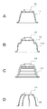
図5および図6に、本開示に係るヘッドホンにおける弾性部材の変形例を示す。図5はハウジングに固定される部位を下方に示し、弾性部材に固定的に取り付けられるユニットホルダ10を上方に示した。
(Modification of elastic member)
5 and 6 show a modification of the elastic member in the headphones according to the present disclosure. FIG. 5 shows the part fixed to the housing below, and the
図5A〜図5Cは、弾性部材が可撓性を有する膜状体である態様の変形例を示す。図5Aに示す膜状弾性体11は、図2〜図4に示した膜状弾性体11と同一部材であるので、同一参照符号を付している。図5Bに示す膜状弾性体110には、ハウジングに固定される部位からユニットホルダ10に固定される部位に至るまでに肩部19が設けられている。肩部19を設けると、ドライバユニット部7の移動による膜状弾性体110の変形が生じるときに、肩部19近傍が優先的に変形する。例えば肩部19を厚肉に形成しておくことにより肩部の強度が向上するので、膜状弾性体110が反復して変形したとしても不可逆的な変形または破断が生じ難くなり、ヘッドホンの高い信頼性を得ることができる。図5Cに示す膜状弾性体111はその周側面が蛇腹状に形成されている。膜状弾性体111は蛇腹状の形状に起因する付勢力を有するので、上記膜状弾性体11および110等に比べて弾性の低い材料を用いることができるようになる。図5Dに示す弾性部材は、板バネ20を複数用いた態様である。板バネ20は細長い薄板状の付勢部材であり、ゼンメンバン等によってハウジングに固定される一端部からユニットホルダ10に固定される他端部まで湾曲して配設される。細長い板バネ20を用いる場合は、様々な方向にドライバユニットが傾斜することができるように、ユニットホルダ10の周縁に等間隔に複数本の板バネ20を配置すると良い。
5A to 5C show a modification of an embodiment in which the elastic member is a flexible film-like body. The film-like
図6は、弾性部材がバネを有する蝶番である態様の一例を示す。ユニットホルダ10は、図6に示すように、受板21と回動軸部22を介して接続されている。受板21は、ハウジングの適宜の位置に固定されている。ユニットホルダ10と受板21との間には付勢部材であるコイルバネ23が付設されている。ヘッドホンが未装着状態であるときは、コイルバネ23の付勢力によってユニットホルダ10が受板21から離れる方向に付勢される。ヘッドホンが装着状態になると、耳介に押圧されたドライバユニットがユニットホルダ10と共に、コイルバネ23の付勢力に抗しつつ、回動軸部22を軸として受板21に近づく方向に移動するようになっている。
FIG. 6 shows an example in which the elastic member is a hinge having a spring. As shown in FIG. 6, the
本開示に係るヘッドホンにおいてドライバユニットはハウジングに対して可動であるが、さらに好ましくは装着者の外耳に最も押圧される方向にドライバユニットが傾斜可能であることが挙げられる。装着者の外耳に最も押圧される方向にドライバユニットが傾斜するということは、本開示に係るヘッドホンを装着したときに装着者の耳介の形状にドライバユニットが沿うようになることであり、装着者にとっては耳介がドライバユニットから押圧されているという感覚を惹起し難い。よって、本開示に係るヘッドホンは、装着者が圧迫感を感じることなく装着することができるので、従来のヘッドホンに比べて装着時の快適性が向上している。 In the headphones according to the present disclosure, the driver unit is movable with respect to the housing. More preferably, the driver unit can be tilted in a direction that is most pressed against the outer ear of the wearer. The fact that the driver unit tilts in the direction most pressed against the outer ear of the wearer means that when the headphones according to the present disclosure are worn, the driver unit comes to follow the shape of the ear of the wearer. It is difficult for a person to provoke a sense that the auricle is being pressed from the driver unit. Therefore, the headphone according to the present disclosure can be worn without feeling a sense of pressure by the wearer, and thus comfort when worn is improved as compared with conventional headphones.
弾性部材が膜状体、特に孔の無い膜状体であると、膜状体が、装着者の耳介側とドライバユニットからハウジングの背面側とにハウジング内部を隔絶することになる。これにより、ドライバユニットからハウジングの背面側に放出されて装着者の耳介側に回り込もうとする音が、弾性部材によって遮断されるので、装着者はドライバユニットから耳介に向けて放出された音のみを聴くことができる。さらに、装着者の耳介側に回り込む音だけでなく、外界の騒音等も弾性部材によって遮断される。つまり、膜状体である弾性部材は、不要な音の防振材および制振材として作用する。なお、膜状体の周側面の形状が蛇腹状であると、膜状体に伝わる振動が減衰し易いので、防振材および制振材としての作用が強くなる。したがって、本開示に係るヘッドホンは、弾性部材として膜状体を用いると音質がより一層向上する。 When the elastic member is a film-like body, particularly a film-like body having no holes, the film-like body isolates the inside of the housing from the auricle side of the wearer and the back side of the housing from the driver unit. As a result, the sound released from the driver unit to the back side of the housing and going around the wearer's auricle is blocked by the elastic member, so that the wearer is released from the driver unit toward the auricle. Can only hear the sound. Furthermore, not only the sound that wraps around the wearer's auricle side, but also external noise and the like are blocked by the elastic member. That is, the elastic member, which is a film-like body, acts as an anti-vibration material and a damping material for unnecessary sound. If the shape of the peripheral side surface of the film-like body is bellows, vibrations transmitted to the film-like body are easily attenuated, so that the action as a vibration isolating material and a vibration damping material is strengthened. Therefore, the sound quality of the headphones according to the present disclosure is further improved when a film-like body is used as the elastic member.
ドライバユニットの傾斜方向が略一方向であると判明している場合は、弾性部材が蝶番である態様を採用するのが良い。弾性部材が蝶番である態様は上記膜状体を用いる態様に比べて作製が容易であるので、ヘッドホン製造工程の簡素化を図ることができる。 When it is found that the inclination direction of the driver unit is substantially one direction, it is preferable to adopt a mode in which the elastic member is a hinge. Since the embodiment in which the elastic member is a hinge is easier to manufacture than the embodiment using the film-like body, the headphone manufacturing process can be simplified.
以上、本開示の実施形態について具体的に説明したが、本開示は、上述の実施形態に限定されるものではなく、本開示の技術的思想に基づく各種の変形が可能である。 Although the embodiment of the present disclosure has been specifically described above, the present disclosure is not limited to the above-described embodiment, and various modifications based on the technical idea of the present disclosure are possible.
例えば、上述の実施形態において挙げた構成、方法、工程、形状、材料および数値などはあくまでも例に過ぎず、必要に応じてこれと異なる構成、方法、工程、形状、材料および数値などを用いてもよい。 For example, the configurations, methods, processes, shapes, materials, numerical values, and the like given in the above-described embodiments are merely examples, and different configurations, methods, processes, shapes, materials, numerical values, and the like are used as necessary. Also good.
さらに、上述の実施形態の構成、方法、工程、形状、材料および数値などは、本開示の主旨を逸脱しない限り、互いに組み合わせることが可能である。 Furthermore, the configurations, methods, processes, shapes, materials, numerical values, and the like of the above-described embodiments can be combined with each other without departing from the gist of the present disclosure.
1・・・ヘッドホン、2・・・ヘッドバンド、3・・・スライダ、4・・・ハンガ、5・・・ハウジング、6・・・イヤパッド、7・・・ドライバユニット部、8・・・接合部、9・・・案内部材、10・・・ユニットホルダ、11・・・膜状弾性体、12・・・ゼンメンバン、13・・・ストッパ、14・・・ドライバユニット、15・・・ユニットカバー、16・・・耳介用パッド、17・・・当接面、18・・・規制部、19・・・肩部、20・・・板バネ、21・・・受板、22・・・回動軸部、23・・・コイルバネ、H・・・側頭部、E・・・耳介
DESCRIPTION OF
Claims (4)
可撓性を有し、孔のない膜状体により形成された筒状の弾性部材であって、一端開口部が上記ハウジングの他端開口部に固定され、他端開口部の外側にドライバユニットが取り付けられた連結部材と
を備えるヘッドホン。 A substantially cylindrical housing with an ear pad attached around one end opening;
A cylindrical elastic member formed of a flexible film-shaped body having no holes, one end opening being fixed to the other end opening of the housing, and a driver unit outside the other end opening A headphone comprising a connecting member to which is attached .
Priority Applications (4)
| Application Number | Priority Date | Filing Date | Title |
|---|---|---|---|
| JP2012018276A JP5910119B2 (en) | 2012-01-31 | 2012-01-31 | headphone |
| US13/743,134 US8965029B2 (en) | 2012-01-31 | 2013-01-16 | Headphone |
| CN2013100242504A CN103227967A (en) | 2012-01-31 | 2013-01-23 | Headphone |
| BRBR102013001868-6A BR102013001868A2 (en) | 2012-01-31 | 2013-01-24 | Earphone |
Applications Claiming Priority (1)
| Application Number | Priority Date | Filing Date | Title |
|---|---|---|---|
| JP2012018276A JP5910119B2 (en) | 2012-01-31 | 2012-01-31 | headphone |
Publications (3)
| Publication Number | Publication Date |
|---|---|
| JP2013157879A JP2013157879A (en) | 2013-08-15 |
| JP2013157879A5 JP2013157879A5 (en) | 2015-02-12 |
| JP5910119B2 true JP5910119B2 (en) | 2016-04-27 |
Family
ID=48838187
Family Applications (1)
| Application Number | Title | Priority Date | Filing Date |
|---|---|---|---|
| JP2012018276A Active JP5910119B2 (en) | 2012-01-31 | 2012-01-31 | headphone |
Country Status (4)
| Country | Link |
|---|---|
| US (1) | US8965029B2 (en) |
| JP (1) | JP5910119B2 (en) |
| CN (1) | CN103227967A (en) |
| BR (1) | BR102013001868A2 (en) |
Families Citing this family (16)
| Publication number | Priority date | Publication date | Assignee | Title |
|---|---|---|---|---|
| US8861770B2 (en) * | 2013-01-23 | 2014-10-14 | Koss Corporation | Headband for personal speakers |
| US8737668B1 (en) * | 2013-01-23 | 2014-05-27 | Koss Corporation | Headband for personal speakers |
| DE102013222231A1 (en) * | 2013-10-31 | 2015-04-30 | Sennheiser Electronic Gmbh & Co. Kg | receiver |
| US9445182B2 (en) * | 2014-02-04 | 2016-09-13 | David Cohen | Headphones with rotatable ear cup |
| EP2919482B1 (en) * | 2014-03-13 | 2019-11-06 | LG Electronics Inc. | Wireless ear piece |
| KR102229667B1 (en) * | 2014-09-05 | 2021-03-18 | 엘지전자 주식회사 | Electronic device and system comprising it |
| CN107003518B (en) | 2015-07-30 | 2020-08-28 | 深圳市柔宇科技有限公司 | Head-mounted electronic device |
| JP6630371B2 (en) * | 2015-07-30 | 2020-01-15 | シェンジェン ロイオル テクノロジーズ カンパニー リミテッドShenzhen Royole Technologies Co., Ltd. | Head mounted electronic devices |
| US10405079B2 (en) * | 2015-08-07 | 2019-09-03 | New Audio LLC | Audio headset having arm-to-yoke coupling features and related technology |
| US9854348B2 (en) * | 2016-04-04 | 2017-12-26 | Nikola Taisha Naylor-Warren | Flexible conformal cushioned headphones |
| US10880633B2 (en) | 2016-06-22 | 2020-12-29 | Dolby Laboratories Licensing Corporation | Headphones and headphone systems |
| EP3337181B1 (en) * | 2016-12-15 | 2020-02-05 | GN Audio A/S | Earphone with earphone housing and speaker housing |
| US10454198B2 (en) * | 2017-06-21 | 2019-10-22 | Goertek Technology Co., Ltd. | Connecting mechanism |
| US10567860B2 (en) * | 2018-05-29 | 2020-02-18 | Evga Corporation | Open-close type earphone structure |
| JP7266872B2 (en) * | 2019-09-13 | 2023-05-01 | 株式会社オーディオテクニカ | headphones and earmuffs |
| CN110896513A (en) * | 2019-12-19 | 2020-03-20 | 歌尔科技有限公司 | Head-wearing earphone |
Family Cites Families (18)
| Publication number | Priority date | Publication date | Assignee | Title |
|---|---|---|---|---|
| AT295618B (en) * | 1969-04-25 | 1972-01-10 | Akg Akustische Kino Geraete | Headphones, in particular for the stereophonic reproduction of sound events |
| JPS591291U (en) * | 1982-06-24 | 1984-01-06 | パイオニア株式会社 | head horn |
| JP3252205B2 (en) * | 1994-06-01 | 2002-02-04 | アツデン株式会社 | Closed headphones |
| JP3950750B2 (en) | 2002-06-28 | 2007-08-01 | 株式会社オーディオテクニカ | headphone |
| US7680267B2 (en) * | 2005-07-01 | 2010-03-16 | Plantronics, Inc. | Headset with a retractable speaker portion |
| DE602005010713D1 (en) * | 2005-10-21 | 2008-12-11 | Akg Acoustics Gmbh | Earphones with improved earmold suspension |
| US8085966B2 (en) * | 2007-01-10 | 2011-12-27 | Allan Amsel | Combined headphone set and portable speaker assembly |
| US20080170738A1 (en) * | 2007-01-16 | 2008-07-17 | Sony Ericsson Mobile Communications Ab | Adjustable earphones for portable devices |
| JP2008283281A (en) * | 2007-05-08 | 2008-11-20 | Audio Technica Corp | Headphone unit and headphone |
| US8503710B1 (en) * | 2007-06-01 | 2013-08-06 | Plantronics, Inc. | Headset with rotatable earpiece |
| CN201153314Y (en) * | 2008-01-04 | 2008-11-19 | 黄天旭 | Portable combine stereo micro sound box |
| TWM343997U (en) * | 2008-04-11 | 2008-11-01 | Transpower Technology Co Ltd | Speaker structure |
| USD610572S1 (en) * | 2009-05-01 | 2010-02-23 | SDI Technologies, Inc,. | Expandable stereo speaker |
| CN101938681A (en) * | 2010-09-10 | 2011-01-05 | 鸿富锦精密工业(深圳)有限公司 | Speaker with audio cavity |
| USD692411S1 (en) * | 2011-09-02 | 2013-10-29 | Sdi Technologies, Inc. | Cup holder bluetooth speakerphone system |
| USD694218S1 (en) * | 2011-09-14 | 2013-11-26 | IdeaVillage Products, Inc | Portable speaker |
| USD691587S1 (en) * | 2012-03-09 | 2013-10-15 | Fka Distributing Co., Llc | Speaker |
| USD692413S1 (en) * | 2012-03-23 | 2013-10-29 | Sdi Technologies, Inc. | Portable speakers with rechargeable battery |
-
2012
- 2012-01-31 JP JP2012018276A patent/JP5910119B2/en active Active
-
2013
- 2013-01-16 US US13/743,134 patent/US8965029B2/en active Active
- 2013-01-23 CN CN2013100242504A patent/CN103227967A/en active Pending
- 2013-01-24 BR BRBR102013001868-6A patent/BR102013001868A2/en not_active IP Right Cessation
Also Published As
| Publication number | Publication date |
|---|---|
| US20130195307A1 (en) | 2013-08-01 |
| JP2013157879A (en) | 2013-08-15 |
| BR102013001868A2 (en) | 2015-06-02 |
| CN103227967A (en) | 2013-07-31 |
| US8965029B2 (en) | 2015-02-24 |
Similar Documents
| Publication | Publication Date | Title |
|---|---|---|
| JP5910119B2 (en) | headphone | |
| US8194910B2 (en) | Headphones | |
| US8532324B2 (en) | Headphone | |
| US8208672B2 (en) | Headphone | |
| TWI572215B (en) | Earphone structure | |
| WO2012039491A1 (en) | Headset for helmet and helmet comprising headset | |
| WO2012026386A1 (en) | Ear speaker | |
| US9497533B2 (en) | Fine tuning structure for headphones and headphone | |
| WO2011007448A1 (en) | Earphone, and electronic device | |
| WO2016151952A1 (en) | Wearable device | |
| JP2009055248A (en) | Earphone | |
| US11805353B2 (en) | Headphone | |
| JP2017112446A (en) | Headphone ear pad, headphone, and earmuff | |
| JP2000201390A (en) | Headphones | |
| JP5256852B2 (en) | headphone | |
| JP2016015609A (en) | headphone | |
| JP5704617B2 (en) | earphone | |
| JP5392429B2 (en) | earphone | |
| KR102484202B1 (en) | The headset apparatus | |
| US20230224616A1 (en) | Headphones and wearable device | |
| JP6460968B2 (en) | earphone | |
| KR20230091751A (en) | Headphone and wearable device | |
| CN116569565A (en) | Edge, speaker unit, microphone, and acoustic processing device | |
| JP5360322B2 (en) | earphone | |
| JP5725090B2 (en) | earphone |
Legal Events
| Date | Code | Title | Description |
|---|---|---|---|
| A521 | Request for written amendment filed |
Free format text: JAPANESE INTERMEDIATE CODE: A523 Effective date: 20141217 |
|
| A621 | Written request for application examination |
Free format text: JAPANESE INTERMEDIATE CODE: A621 Effective date: 20141217 |
|
| A977 | Report on retrieval |
Free format text: JAPANESE INTERMEDIATE CODE: A971007 Effective date: 20150713 |
|
| A131 | Notification of reasons for refusal |
Free format text: JAPANESE INTERMEDIATE CODE: A131 Effective date: 20150721 |
|
| A521 | Request for written amendment filed |
Free format text: JAPANESE INTERMEDIATE CODE: A523 Effective date: 20150914 |
|
| TRDD | Decision of grant or rejection written | ||
| A01 | Written decision to grant a patent or to grant a registration (utility model) |
Free format text: JAPANESE INTERMEDIATE CODE: A01 Effective date: 20160301 |
|
| A61 | First payment of annual fees (during grant procedure) |
Free format text: JAPANESE INTERMEDIATE CODE: A61 Effective date: 20160314 |
|
| R151 | Written notification of patent or utility model registration |
Ref document number: 5910119 Country of ref document: JP Free format text: JAPANESE INTERMEDIATE CODE: R151 |
|
| R250 | Receipt of annual fees |
Free format text: JAPANESE INTERMEDIATE CODE: R250 |
|
| R250 | Receipt of annual fees |
Free format text: JAPANESE INTERMEDIATE CODE: R250 |