JP5908687B2 - Spiral flow generator - Google Patents
Spiral flow generator Download PDFInfo
- Publication number
- JP5908687B2 JP5908687B2 JP2011182817A JP2011182817A JP5908687B2 JP 5908687 B2 JP5908687 B2 JP 5908687B2 JP 2011182817 A JP2011182817 A JP 2011182817A JP 2011182817 A JP2011182817 A JP 2011182817A JP 5908687 B2 JP5908687 B2 JP 5908687B2
- Authority
- JP
- Japan
- Prior art keywords
- cylindrical container
- peripheral surface
- filter
- fluid
- flow
- Prior art date
- Legal status (The legal status is an assumption and is not a legal conclusion. Google has not performed a legal analysis and makes no representation as to the accuracy of the status listed.)
- Active
Links
- 230000002093 peripheral effect Effects 0.000 claims description 86
- 239000012530 fluid Substances 0.000 claims description 36
- 238000007599 discharging Methods 0.000 claims description 13
- 230000001105 regulatory effect Effects 0.000 claims description 4
- 239000000843 powder Substances 0.000 description 53
- 239000008188 pellet Substances 0.000 description 36
- 238000003466 welding Methods 0.000 description 3
- 238000012423 maintenance Methods 0.000 description 2
- 238000004519 manufacturing process Methods 0.000 description 2
- 239000000463 material Substances 0.000 description 2
- 239000011347 resin Substances 0.000 description 2
- 229920005989 resin Polymers 0.000 description 2
- 238000004140 cleaning Methods 0.000 description 1
- 239000007788 liquid Substances 0.000 description 1
- 239000002184 metal Substances 0.000 description 1
- 239000007769 metal material Substances 0.000 description 1
- 239000000203 mixture Substances 0.000 description 1
- 238000000465 moulding Methods 0.000 description 1
- 239000002245 particle Substances 0.000 description 1
- 238000004080 punching Methods 0.000 description 1
- 230000007704 transition Effects 0.000 description 1
Images


Description
本発明は、流体の螺旋流を発生させる螺旋流発生装置に関する。 The present invention relates to a spiral flow generator that generates a spiral flow of a fluid.
従来より、螺旋流を利用することにより、複数種類の物体を混合することや、混合状態の複数種類の物体を分離することが行われている。 Conventionally, a plurality of types of objects are mixed or a plurality of types of mixed objects are separated by using a spiral flow.
例えば、特許文献1に記載された螺旋流発生装置は、円筒状容器と、その容器の外周面からその接線方向に延びる供給用管路と、容器内に収容された円筒状のメッシュフィルタとを有する。微粉混入ペレットが、搬送流によって供給用管路を介して容器内に供給される。微粉混入ペレットを含む気流(混合気流)は、メッシュフィルタの内部空間に入り、メッシュフィルタの内周面に沿って流れ、螺旋状に流れる(螺旋流となる)。混合気流がメッシュフィルタの内周面に沿って螺旋状に流れる際に、混合気流内の微粉はメッシュフィルタを通過し、メッシュフィルタの外部に分離される。これにより、ペレットから微粉が分離される。 For example, a spiral flow generator described in Patent Document 1 includes a cylindrical container, a supply pipe extending in a tangential direction from the outer peripheral surface of the container, and a cylindrical mesh filter accommodated in the container. Have. The fine powder-mixed pellets are supplied into the container through the supply pipeline by the conveying flow. The airflow (mixed airflow) containing fine powder-mixed pellets enters the interior space of the mesh filter, flows along the inner peripheral surface of the mesh filter, and flows spirally (becomes a spiral flow). When the mixed airflow flows spirally along the inner peripheral surface of the mesh filter, the fine powder in the mixed airflow passes through the mesh filter and is separated to the outside of the mesh filter. Thereby, a fine powder is isolate | separated from a pellet.
しかしながら、特許文献1に記載する螺旋流発生装置のように、円筒状容器の外周面からその接線方向に延びるように管路を該円筒状容器に一体的に形成することは容易ではない。例えば、ドリルによって円筒状容器の外周面にその接線方向に貫通穴を形成し、貫通穴から接線方向に延びるように円管を流体密に円筒状容器の外周面に溶接して管路を形成することは、容易ではない。 However, as in the spiral flow generator described in Patent Document 1, it is not easy to integrally form the pipe line in the cylindrical container so as to extend in the tangential direction from the outer peripheral surface of the cylindrical container. For example, a through hole is formed in the tangential direction on the outer peripheral surface of a cylindrical container with a drill, and a circular pipe is fluid-tightly welded to the outer peripheral surface of the cylindrical container so as to extend in the tangential direction from the through hole. It is not easy to do.
そこで、本発明は、管路が円筒状容器に一体的に形成される螺旋流発生装置の作製を容易にすることを課題とする。 Then, this invention makes it a subject to make easy manufacture of the spiral flow generator by which a pipe line is integrally formed in a cylindrical container.
上述の課題を解決するために、本発明の第1の態様によれば、流体の螺旋流を発生させる円筒状の内周面を備えた円筒状容器と、円筒状容器内に収容された円筒状のフィルタと、円筒状容器の外部からフィルタの一方の端の開口を介して該フィルタの内部に流体を供給するための供給流路と、フィルタを通過した流体を円筒状容器から外部に排出するための排出流路と、フィルタの他方の端の開口と接続し、円筒状容器の中心線方向の端部に設けられ、円筒状容器の内周面と同心の円管状の内側管路と、を有し、供給流路がフィルタの一方の端の開口の接線方向に延びる管路によって画定され、排出流路が円筒状容器の外周面から法線方向に延びる管路によって画定され、円筒状容器の内周面に沿う流体の螺旋流の流れ方向と直交する方向に流体を案内して、流体を排出流路に導くガイド部材を円筒状容器内にさらに有し、排出流路の内部空間と円筒状容器の内部空間とを連絡する貫通穴が、内側管路と対向するように円筒状容器の内周面で開口する、螺旋流発生装置が提供される。
In order to solve the above-mentioned problem, according to the first aspect of the present invention, a cylindrical container having a cylindrical inner peripheral surface for generating a spiral flow of fluid, and a cylinder accommodated in the cylindrical container Filter, a supply channel for supplying fluid from the outside of the cylindrical container to the inside of the filter through the opening of one end of the filter, and the fluid that has passed through the filter is discharged from the cylindrical container to the outside A discharge flow path for connecting to the opening of the other end of the filter, provided at the end of the cylindrical container in the center line direction, and a cylindrical inner pipe concentric with the inner peripheral surface of the cylindrical container; And the supply flow path is defined by a conduit extending tangentially to the opening at one end of the filter, and the discharge flow path is defined by a conduit extending in a normal direction from the outer peripheral surface of the cylindrical container. In a direction perpendicular to the flow direction of the spiral flow of the fluid along the inner peripheral surface of the container Guide the body, the fluid further have a guide member for guiding the exhaust flow path in a cylindrical container, the through hole communicating the inner space of the inner space and the cylindrical container of the discharge passage, and an inner pipe There is provided a spiral flow generator that opens on the inner peripheral surface of a cylindrical container so as to face each other.
本発明の第2の態様によれば、流体の螺旋流を発生させる円筒状の内周面を備えた円筒状容器と、円筒状容器内に収容された円筒状のフィルタと、円筒状容器の外部からフィルタの一方の端の開口を介して該フィルタの内部に流体を供給するための供給流路と、フィルタを通過した流体を円筒状容器から外部に排出するための排出流路と、フィルタの他方の端の開口と接続し、円筒状容器の中心線方向の端部に設けられ、円筒状容器の内周面と同心の円管状の内側管路と、を有し、供給流路がフィルタの一方の端の開口の接線方向に延びる管路によって画定され、排出流路が円筒状容器の中心線方向の端部の一方から円筒状容器の中心線方向に延びる管路によって画定され、円筒状容器の内周面に沿う流体の螺旋流の流れ方向と直交する方向に流体を案内して、流体を排出流路に導くガイド部材を円筒状容器内にさらに有し、排出流路の内部空間と円筒状容器の内部空間とを連絡する貫通穴が、円筒状容器と内側管路との間の該円筒状容器の端部の部分で開口する、螺旋流発生装置が提供される。
According to the second aspect of the present invention, a cylindrical container having a cylindrical inner peripheral surface for generating a spiral flow of fluid, a cylindrical filter housed in the cylindrical container, and a cylindrical container A supply channel for supplying fluid to the inside of the filter from the outside through an opening at one end of the filter, a discharge channel for discharging the fluid that has passed through the filter to the outside from the cylindrical container, and the filter An opening at the other end of the cylindrical container, provided at an end of the cylindrical container in the center line direction, and having a cylindrical inner pipe concentric with the inner peripheral surface of the cylindrical container, and a supply flow path A conduit defined by a conduit extending tangentially to the opening at one end of the filter, and a discharge channel defined by a conduit extending in the direction of the centerline of the cylindrical container from one of the centerline ends of the cylindrical container; A direction orthogonal to the flow direction of the spiral flow of the fluid along the inner peripheral surface of the cylindrical container Guide the fluid, the fluid further have a guide member for guiding the exhaust flow path in a cylindrical container, the through hole communicating the inner space of the inner space and the cylindrical container of the discharge passage, a cylindrical container A spiral flow generator is provided that opens at the end portion of the cylindrical container between the inner conduit .
本発明の第3の態様によれば、ガイド部材が、円筒状容器の内周面に沿う流体の螺旋流の流れ方向と交差するように円筒状容器の中心側から内周面に向かって延びて、流体を排出流路に案内するガイド面を備える、第1または第2の態様に記載の螺旋流発生装置が提供される。 According to the third aspect of the present invention, the guide member extends from the center side of the cylindrical container toward the inner peripheral surface so as to intersect the flow direction of the spiral flow of the fluid along the inner peripheral surface of the cylindrical container. Thus, the spiral flow generation device according to the first or second aspect is provided, which includes a guide surface that guides the fluid to the discharge channel.
本発明の第4の態様によれば、ガイド部材が、ガイド面に案内されている流体の排出流路に向かう方向以外の方向への流れを規制する規制面を備える、第3の態様に記載の螺旋流発生装置が提供される。 According to a fourth aspect of the present invention, in the third aspect, the guide member includes a regulation surface that regulates a flow in a direction other than a direction toward the discharge flow path of the fluid guided by the guide surface. A spiral flow generator is provided.
本発明の第5の態様によれば、内側管路の外周面が、ガイド部材の規制面の一部として機能する、第4の態様に記載の螺旋流発生装置が提供される。 According to a fifth aspect of the present invention, the outer peripheral surface of the inner side conduit functions as part of the regulating surface of the guide member, helical flow generating apparatus according to a fourth aspect is provided.
本発明によれば、流体を排出するための排出流路を画定する管路が円筒状容器の外周面から法線方向に延びるため、円筒状容器の外周面からその接線方向に延びる場合に比べて、管路を円筒状容器に容易に一体的に形成することができる。 According to the present invention, since the pipe line that defines the discharge flow path for discharging the fluid extends in the normal direction from the outer peripheral surface of the cylindrical container, compared with the case of extending from the outer peripheral surface of the cylindrical container in the tangential direction. Thus, the pipe line can be easily formed integrally with the cylindrical container.
また、ガイド部材が、円筒状容器の内周面に沿う流体の螺旋流が管路に向かうように案内する。このようなガイド部材により、管路が円筒状容器の外周面から法線方向に延びていても、円筒状容器の内周面に沿う流体の螺旋流が管路内にスムーズに流れることができる。 Moreover, a guide member guides so that the spiral flow of the fluid along the inner peripheral surface of a cylindrical container may go to a pipe line. By such a guide member, even if the pipe line extends in the normal direction from the outer peripheral surface of the cylindrical container, the spiral flow of the fluid along the inner peripheral surface of the cylindrical container can smoothly flow into the pipe line. .
したがって、螺旋流発生装置の螺旋流を発生させる機能を損なうことなく、螺旋流発生装置の作製を容易にすることができる。 Therefore, it is possible to facilitate the production of the spiral flow generator without impairing the function of generating the spiral flow of the spiral flow generator.
(実施の形態1)
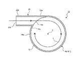
図1は、本発明の実施の形態1に係る螺旋流発生装置の構成の一部を概略的に示している。図2は、図1のA−A断面図であり、図3は図1のB−B断面図である。
(Embodiment 1)
FIG. 1 schematically shows a part of the configuration of a spiral flow generator according to Embodiment 1 of the present invention. 2 is a cross-sectional view taken along the line AA in FIG. 1, and FIG. 3 is a cross-sectional view taken along the line BB in FIG.
なお、本明細書で言う「螺旋方向」の流れや「螺旋流」は、流体が直線軸(本実施の形態の場合、後述する中心線C)を中心として旋回しつつ、直線軸方向に進行する流れを言う。また、本発明で言う「流体」は、気体や液体に限らず、流動性を備える物体を言う。 In addition, the flow in the “spiral direction” and the “spiral flow” referred to in the present specification travel in the direction of the linear axis while the fluid swirls around the linear axis (in the case of the present embodiment, a center line C described later). Say the flow to do. The “fluid” referred to in the present invention is not limited to gas or liquid, but refers to an object having fluidity.
図1〜3に示す螺旋流発生装置10は、本発明に係る螺旋流発生装置の一例であって、樹脂のペレット(粉粒体)に混入している微粉を分離するためのものである。 1-3 is an example of the spiral flow generator according to the present invention, and is for separating fine powder mixed in resin pellets (powder particles).
図1に示すように、螺旋流発生装置10は、螺旋流を発生させるための本体12と、ペレットに混入する微粉を分離するためのフィルタ14と、螺旋流をガイドするガイド部材16とを有する。
As shown in FIG. 1, the
螺旋流発生装置10の本体12は、金属材料から作製されており、円筒状容器18と、円筒状容器18内に微粉混入ペレットを供給するための供給流路を画定する供給用管路20と、微粉が分離されたペレットを円筒状容器18の外部に排出するためのペレット用排出流路を画定するペレット排出用管路22と、微粉を円筒状容器18の外部に排出するための微粉用排出流路を画定する微粉排出用管路24とを備える。
The
螺旋流発生装置10の本体12の円筒状容器18は、中心線Cを備える円筒体形状である。具体的には、円筒状容器18は、その内部空間にフィルタ14とガイド部材16とを取り付けるために、またメンテナンスのために、3つのパーツ(18−1〜18−3)に分離可能に構成されている。
The
なお、図1に示す本体12の円筒状容器18は、中心線Cと直交する断面の面積が一定の形状であるが、本発明に係る円筒状容器は、中心線方向位置によって断面積が異なる形状であってもよい。
The
供給用管路20は、微粉混入ペレットを円筒状容器18の内部空間に供給するためのものであって、円管から作製されている。微粉混入ペレットは、搬送流によって供給用管路20を介して円筒状容器18の内部空間に供給される。
The
図2に示すように、供給用管路20の一端20aが、円筒状容器18の外周面18aに一体的に取り付けられている、例えば溶接によって接合されている。具体的には、供給用管路20は、円筒状容器18の接線方向に延びるように、円筒状容器18の外周面18aに一体的に形成されている。
As shown in FIG. 2, one
なお、ここで言う「接線方向」は、中心線Cと直交する円筒状容器18の円形断面と接する接線が延びる方向を言う。
The “tangential direction” here refers to a direction in which a tangent line in contact with the circular cross section of the
また、供給用管路20の内部空間と円筒状容器18の内部空間とを連絡するために貫通穴18bが、円筒状容器18に形成されている。さらに、供給用管路20は、その他端(円筒状容器18に非接続の端)20bに、微粉混入ペレットを含む搬送流F(以下、「混合気流F」と称する)を取り込むための開口20cを備えている。
Further, a
このような供給用管路20により、図2に示すように、供給用管路20を介して円筒状容器18の内部空間に流入した混合気流Fは、円筒状容器18(その内部空間の上側)の内周面18cに沿って流れることによって螺旋流となり、図1に示すようにフィルタ14の内部空間に流入する。
As shown in FIG. 2, the mixed air flow F that has flowed into the internal space of the
このフィルタ14は、混合気流Fから微粉を分離するフィルタであって、中心線Cを備える円錐台状の円筒体である。フィルタ14は、例えばパンチングメタルから作製される。
The
フィルタ14はまた、その両端に、大きさが異なる開口14a,14bを備える。フィルタ14の大きい方の開口14aは、円筒状容器18の内部空間の上側で発生した螺旋方向の混合気流Fをフィルタ14の内部空間に取り込むためのものである。一方、小さい開口14bは、微粉が分離されたペレットをフィルタ14の外部に排出するためのものであり、本体12のペレット排出用管路22に接続されている。
The
また、このフィルタ14は、微粉は通過できるがペレットは通過できない大きさの複数のフィルタ孔14c(いわゆるフィルタの目)を備える。このフィルタ孔14cにより、フィルタ14の内部空間と、フィルタ14と円筒状容器18の内周面18cとの間の空間とが連絡される。
The
このようなフィルタ14により、混合気流Fが開口14aから開口14bに向かってフィルタ14の内周面に沿って螺旋方向に流れ、その際にフィルタ孔14cを介して微粉がフィルタ14と円筒状容器18の内周面18cとの間の空間に分離される。微粉は、フィルタ14のフィルタ孔14cを通過した気流によって微粉排出用管路24に向かって運ばれる。一方、フィルタ14によって微粉が分離されたペレットは、開口14bを介してペレット排出用管路22の内部空間に流入する。
By such a
このペレット排出用管路22は、微粉が分離されたペレットを円筒状容器18の外部に排出するためのものであって、円管から作製されている。また、ペレット排出用管路22は、円筒状容器18の中心線C方向の一方の端部(底側)18dに接合されており、端部18dから中心線C方向に延びている。さらに、ペレット排出出用管路22は、円筒状容器18の内周面18cと同心にその内部空間に配置されている。さらにまた、ペレット排出用管路22の内部空間と円筒状容器18の外部とを連絡する開口18eが端部18dに形成されている。
The
このようなペレット排出用管路22により、フィルタ14によって微粉が分離されたペレットが円筒状容器18の外部に排出される。なお、例えば、ペレット排出用管路22の開口18eは、樹脂成形装置のペレット投入口に接続される。
With such a
一方、フィルタ14のフィルタ孔14cを通過した微粉を含む気流F’(以下、「混合気流F’」と称する)は、円筒状容器18の内周面18cに沿って流れることによって螺旋流となり、微粉排出用管路24に向かって流れる。
On the other hand, the airflow F ′ containing fine powder that has passed through the
この微粉排出用管路24は、円筒状容器18の内周面18cに沿って螺旋方向に流れる混合気流F’を外部に排出するためのものであって、円管から作製されている。図3に示すように、微粉排出用管路24の一端24aが、円筒状容器18の外周面18aに一体的に取り付けられている、例えば溶接によって接合されている。
The fine
具体的には、微粉排出用管路24は、図3に示すように、円筒状容器18の外周面18aの法線方向に延びるように、円筒状容器18の外周面18aに一体的に形成されている。
Specifically, as shown in FIG. 3, the fine
なお、ここで言う「法線方向」は、円筒状容器18の中心線Cと直交する方向でもある。
The “normal direction” referred to here is also a direction orthogonal to the center line C of the
また、微粉排出用管路24の内部空間と円筒状容器18の内部空間とを連絡するために貫通穴18fが円筒状容器18に形成されている。さらに、微粉排出用管路24は、その他端(円筒状容器18に非接続の端)24bに、螺旋流発生装置10の構成要素である円筒状容器18内の空気を吸引する吸引装置(図示せず)と接続するための開口24cを備えている。なお、図示されてはいないが、吸引装置に向かう混合気流F’内の微粉を捕らえて回収するためのフィルタが、開口24cと吸引装置との間に設けられている。
Further, a through hole 18 f is formed in the
円筒状容器18の内周面18cに沿って螺旋方向に流れる混合気流F’が、微粉排出用管路24の内部空間に流入するように、ガイド部材16が設けられている。
The
説明すると、図3に示すように、円筒状容器18の内周面18cに沿って螺旋方向に流れる混合気流F’は、円筒状容器18の外周面18aの法線方向に延びる微粉排出用管路24の内部空間に流入しにくい。微粉排出用管路24の内部空間に流入するためには、混合気流F’は、流れ方向を約90度変更しなければならない。
If it demonstrates, as shown in FIG. 3, the mixed airflow F 'which flows into a spiral direction along the internal
そのために、ガイド部材16が設けられ、そのガイド部材16は、円筒状容器18の内周面18cに沿って螺旋方向に流れる混合気流F’を、その流れ方向と直交する方向に案内して微粉排出用管路24の内部空間に導くように構成されている。
For this purpose, a
具体的には、このガイド部材16は、例えばプラスチック材料から作製されており、図1や図3に示すように、円筒状容器18の内周面18cとペレット排出用管路22の外周面22aとの間に、また円筒状容器18の端部18d上に設けられている。また、ガイド部材16は、円筒状容器18の内周面18cに沿って螺旋方向に流れる混合気流F’の流れ方向(すなわち、内周面18cの周方向)と交差するように延びるガイド面16aを備えている。
Specifically, the
このガイド部材16のガイド面16aは、具体的には、ペレット排出用管路22の外周面22aから円筒状容器18の内周面18c(具体的には、開口18fの混合気流F’の流れ方向に関して下流側)に延びている。また、ガイド面16aは、円筒状容器18の端部18dから中心線C方向に延びている。
Specifically, the
このようなガイド面16aにより、円筒状容器18の内周面18cに沿って螺旋方向に流れる混合気流F’は、微粉排出用管路24の内部空間にスムーズに流入することができる。
By such a
さらに、ガイド部材16は、図1や図3に示すように、スロープ面16bを備える。スロープ面16bは、円筒状容器18の内周面18cに沿って螺旋方向にガイド面16aに向かって延びている。
Furthermore, the
図3に示すスロープ面16bの場合、その一端16cから時計回り方向に延びてガイド面16aの上方を通過し、また円筒状容器18の端部18dに位置する他端16dまで延びている。
In the case of the
このようなスロープ面16bにより、混合気流F’がガイド面16aに向かうように案内される。
Such a
加えて、ガイド部材16は、図1に示すように、ガイド面16aに案内されている混合気流F’が、微粉排出用管路24に向かって流れずに、円筒状容器18の中心線C方向供給用管路20側に流れることを防止する規制面16eを備える。この規制面16eは、図3に示すように、スロープ面16bの裏側に設けられている。
In addition, as shown in FIG. 1, the
ガイド部材16の規制面16eがガイド面16aに案内されている混合気流F’の流れを規制することに関連して言えば、図1や図3に示すように、円筒状容器18の端部18dやペレット排出用管路22の外周面22aも同様の役割を果たす。円筒状容器18の端部18dは、ガイド面16aに案内されている混合気流F’が、中心線C方向底部18d側に流れることを規制する規制面として機能する。また、ペレット排出用管路22の外周面22aは、ガイド面16aに案内されている混合気流F’が、中心線Cに向かう方向に流れることを規制する規制面として機能する。
When the
なお、ガイド部材16が、ガイド面16aに案内されている混合気流F’の中心線C方向底部18d側方向や中心線Cに向かう方向への流れを規制する規制面を備えてもよい。
Note that the
また、ガイド部材16は、クリーニングなどのメンテナンスを容易にするために、円筒状容器18に着脱可能に構成するのが好ましい。
The
本実施の形態によれば、本体12の円筒状容器18内から微粉を含む混合気流F’を排出するための微粉排出用管路24が円筒状容器18の外周面18aからその法線方向に延びるため、接線方向に延びる場合に比べて、微粉排出用管路24を円筒状容器18の外周面18aに容易に一体的に形成することができる。
According to the present embodiment, the fine
また、ガイド部材16が、円筒状容器18の内周面18cに沿って螺旋方向に流れる混合気流F’が微粉排出用管路24内に向かうように案内する。このようなガイド部材16により、微粉排出用管路24が円筒状容器18の外周面18aからその法線方向に延びていても、円筒状容器18内を螺旋方向に流れる混合気流F’が微粉排出用管路24内にスムーズに流れることができる。
Further, the
したがって、螺旋流発生装置10の螺旋流を発生させる機能を損なうことなく、螺旋流発生装置10の作製を容易にすることができる。
Therefore, the
(実施の形態2)
図4は、本発明の実施の形態2に係る螺旋流発生装置の構成の一部を概略的に示している。図5は、図4のC−C断面図である。
(Embodiment 2)
FIG. 4 schematically shows a part of the configuration of the helical flow generator according to Embodiment 2 of the present invention. 5 is a cross-sectional view taken along the line CC of FIG.
本実施の形態2の螺旋流発生装置と、図1に示す実施の形態1に係る螺旋流発生装置10との違いは、微粉排出用管路が、本体の円筒状容器の外周面ではなく端部に設けられている点である。したがって、この異なる点を中心にして、本実施の形態2の螺旋流発生装置を説明する。
The difference between the spiral flow generation device of the second embodiment and the spiral
図4に示すように、本実施の形態2の螺旋流発生装置110の微粉排出用管路124は、円管から作製されており、円筒状容器118の端部(底側)118dに、その一端が一体的に取り付けられている、例えば溶接によって接合されている。また、微粉排出用管路124は、端部118dから円筒状容器118の中心線C方向外側に延びている。さらに、微粉排出用管路124の内部空間と円筒状容器118の内部空間とを連絡するために開口118fが端部118dに形成されている。
As shown in FIG. 4, the fine
ガイド部材116も、図4や図5に示すように、実施の形態1のガイド部材16と同様に、例えばプラスチック材料から作製されており、円筒状容器118の内周面118cとペレット排出用管路122の外周面122aとの間に、また円筒状容器118の端部118d上に設けられている。また、ガイド部材116は、円筒状容器118の内周面118cに沿って螺旋方向に流れる混合気流(微粉を含む気流)F’の流れ方向(すなわち、内周面118cの周方向)と交差するように延びるガイド面116aを備えている。
As shown in FIGS. 4 and 5, the
このガイド部材116のガイド面116aは、具体的には、ペレット排出用管路122の外周面122aから円筒状容器118の内周面118c(具体的には、開口118fの混合気流F’の流れ方向に関して下流側)に延びている。また、ガイド面116aは、円筒状容器118の端部118dから中心線C方向に延びている。
Specifically, the
このようなガイド面116aにより、円筒状容器118の内周面118cに沿って螺旋方向に流れる混合気流F’は、微粉排出用管路124の内部空間にスムーズに流入することができる。
By such a
本実施の形態2によれば、本体112の円筒状容器118内から微粉を含む混合気流F’を排出するための微粉排出用管路124が円筒状容器118の端部118dから円筒状容器118の中心線C方向外側に延びるため、円筒状容器118の外周面118aからその接線方向に延びる場合に比べて、微粉排出用管路124を円筒状容器118の端部118dに容易に一体的に形成することができる。
According to the second embodiment, the fine
また、ガイド部材116が、円筒状容器118の内周面118cに沿って螺旋方向に流れる混合気流F’が微粉排出用管路124内に向かうように案内する。このようなガイド部材116により、微粉排出用管路124が円筒状容器118の端部118dから中心線C方向外側に延びていても、円筒状容器118内を螺旋方向に流れる混合気流F’が微粉排出用管路124内にスムーズに流れることができる。
In addition, the
したがって、螺旋流発生装置110の螺旋流を発生させる機能を損なうことなく、螺旋流発生装置110の作製を容易にすることができる。
Therefore, the
以上、上述の2つの実施の形態を挙げて本発明を説明したが、本発明はこれらの実施の形態に限定されない。 Although the present invention has been described with reference to the above-described two embodiments, the present invention is not limited to these embodiments.
例えば、上述の実施の形態1,2のガイド部材16,116と異なる構成のガイド部材であってもよい。例えば、微粉排出用管路に向かって開口する出口と、円筒状容器の内周面の周方向に開口する入口と、出口と入口とを連絡する内部流路とを備えるガイド部材であっても、上述のガイド部材16,116と同様の機能を果たすことができる。
For example, a guide member having a configuration different from the
また、例えば、上述の実施の形態1の場合、図2に示すように、本体12の供給用管路20は、円筒状容器18の外周面18aからその接線方向に延びるように、円筒状容器18の外周面18aに一体的に形成されているが、本発明はこれに限らない。供給用管路20も、微粉排出用管路24と同様に、図3に示すように円筒状容器18の外周面18aから法線方向に延びるように、または図4に示すように円筒状容器18の端部(天井側)から中心線C方向外側に延びるように、円筒状容器18に一体的に形成されてもよい。
Further, for example, in the case of the above-described first embodiment, as shown in FIG. 2, the
この場合も、ガイド部材16と同様のガイド部材を設ける必要がある。すなわち、供給用管路20を流れる混合気流(微粉混入ペレットを含む気流)の流れ方向と交差するように延びて、円筒状容器18の内周面18cに沿う周方向に混合気流を案内するガイド部材を設ける必要がある。
Also in this case, it is necessary to provide a guide member similar to the
このようなガイド部材も、上述の実施の形態1や2のガイド部材16,116のガイド面16a,116aと同様に、円筒状容器18の中心C側から内周面18cに向かって延びるガイド面を備えるのが好ましい。また、円筒状容器18の内周面18cに沿って螺旋方向にガイド面の前方から延びて、ガイド面に案内されて周方向に流れる混合気流を螺旋方向に案内するスロープ面を備えるのが好ましい。このようなガイド部材により、供給用管路20内からの混合気流が円筒状容器18の内周面18cに沿う螺旋方向の流れにスムーズに移行することができる。すなわち、供給用管路20が円筒状容器18の外周面18aにその接線方向に一体的に形成されていなくても、スムーズに螺旋流を発生させることができる。
Such a guide member also extends from the center C side of the
なお、このような供給用管路を介して供給された混合気流を案内するガイド部材の場合、円筒状容器の端部(天井側)が、ガイド面に案内されて周方向に流れる混合気流をスロープ面に案内する役割を果たす。また、円筒状容器の端部(天井側)に内周面と同心に内側管路(例えば図1にペレット排出用管路22と類似の管路)を設ければ、その内側管路の外周面も、ガイド面に案内されて周方向に流れる混合気流をスロープ面に案内する役割を果たすことができる。
In the case of a guide member that guides the mixed airflow supplied through such a supply pipeline, the end portion (ceiling side) of the cylindrical container is guided by the guide surface and flows in the circumferential direction. It plays a role of guiding to the slope surface. If an inner pipe (for example, a pipe similar to the
さらに、上述の実施の形態1,2の場合、本体の円筒状容器に一体的に形成されている管路は直線状であるが本発明はこれに限らない。本発明は、広義には、本体の円筒状容器に一体的に形成される側の管路の部分が、円筒状容器の外周面から法線方向に延びる、または円筒状容器の端部から該円筒状容器の中心線方向に延びるものである。 Further, in the case of the above-described first and second embodiments, the pipe line formed integrally with the cylindrical container of the main body is linear, but the present invention is not limited to this. In a broad sense, the present invention broadly defines that the portion of the pipe line formed integrally with the cylindrical container of the main body extends in the normal direction from the outer peripheral surface of the cylindrical container, or from the end of the cylindrical container. It extends in the direction of the center line of the cylindrical container.
加えて、上述の実施の形態1,2の螺旋流発生装置は、ペレットと微粉とを分離するように、混合状態の複数の物体を分離するものであるが、本発明はこれに限らない。本発明は、例えば、複数の物体を螺旋流によって混合する混合装置にも適用可能である。例えば、混合用途の螺旋流発生装置は、複数の物体を供給するための複数の供給用管路と、複数の物体の混合物を排出するための排出用管路とを有する。複数の物体それぞれは、気流とともに対応する供給用管路を介して円筒状容器に供給され、円筒状容器内で混合され、そして排出用管路を介して円筒状容器の外部に排出される。 In addition, the spiral flow generators according to the first and second embodiments described above separate a plurality of mixed objects so as to separate pellets and fine powder, but the present invention is not limited to this. The present invention is also applicable to a mixing device that mixes a plurality of objects by a spiral flow, for example. For example, the spiral flow generating device for mixing use includes a plurality of supply pipes for supplying a plurality of objects and a discharge pipe for discharging a mixture of the plurality of objects. Each of the plurality of objects is supplied to the cylindrical container through the corresponding supply pipe along with the air flow, mixed in the cylindrical container, and discharged to the outside of the cylindrical container through the discharge pipe.
本発明は、ペレットから微粉を分離する用途に限らず、内周面に沿う螺旋流を発生させる装置であれば適用可能である。また、気体の螺旋流に限らず、流体の螺旋流を発生させる装置にも、本発明は適用可能である。 The present invention is not limited to the use for separating fine powder from pellets, but can be applied to any device that generates a spiral flow along the inner peripheral surface. Further, the present invention is applicable not only to a gas spiral flow but also to an apparatus that generates a fluid spiral flow.
10 螺旋流発生装置
16 ガイド部材
18 円筒状容器
18a 外周面
18c 内周面
24 管路(供給用管路)
F’ 螺旋流(混合気流)
DESCRIPTION OF
F 'Spiral flow (mixed air flow)
Claims (5)
円筒状容器内に収容された円筒状のフィルタと、
円筒状容器の外部からフィルタの一方の端の開口を介して該フィルタの内部に流体を供給するための供給流路と、
フィルタを通過した流体を円筒状容器から外部に排出するための排出流路と、
フィルタの他方の端の開口と接続し、円筒状容器の中心線方向の端部に設けられ、円筒状容器の内周面と同心の円管状の内側管路と、を有し、
供給流路がフィルタの一方の端の開口の接線方向に延びる管路によって画定され、
排出流路が円筒状容器の外周面から法線方向に延びる管路によって画定され、
円筒状容器の内周面に沿う流体の螺旋流の流れ方向と直交する方向に流体を案内して、流体を排出流路に導くガイド部材を円筒状容器内にさらに有し、
排出流路の内部空間と円筒状容器の内部空間とを連絡する貫通穴が、内側管路と対向するように円筒状容器の内周面で開口する螺旋流発生装置。 A cylindrical container having a cylindrical inner peripheral surface for generating a spiral flow of fluid;
A cylindrical filter housed in a cylindrical container;
A supply flow path for supplying fluid from the outside of the cylindrical container to the inside of the filter through the opening at one end of the filter;
A discharge passage for discharging the fluid that has passed through the filter from the cylindrical container to the outside ;
Connected to the opening at the other end of the filter, provided at the end of the cylindrical container in the center line direction, and having a cylindrical inner pipe concentric with the inner peripheral surface of the cylindrical container ,
The supply flow path is defined by a conduit extending tangentially to the opening at one end of the filter;
The discharge channel is defined by a pipe line extending in a normal direction from the outer peripheral surface of the cylindrical container;
Guide the fluid in a direction perpendicular to the flow direction of the spiral flow of the fluid along the inner peripheral surface of the cylindrical container, further have a guide member for guiding the fluid to the discharge flow path in a cylindrical container,
A spiral flow generating device in which a through hole that connects the internal space of the discharge channel and the internal space of the cylindrical container opens at the inner peripheral surface of the cylindrical container so as to face the inner pipe line .
円筒状容器内に収容された円筒状のフィルタと、
円筒状容器の外部からフィルタの一方の端の開口を介して該フィルタの内部に流体を供給するための供給流路と、
フィルタを通過した流体を円筒状容器から外部に排出するための排出流路と、
フィルタの他方の端の開口と接続し、円筒状容器の中心線方向の端部に設けられ、円筒状容器の内周面と同心の円管状の内側管路と、を有し、
供給流路がフィルタの一方の端の開口の接線方向に延びる管路によって画定され、
排出流路が円筒状容器の中心線方向の端部の一方から円筒状容器の中心線方向に延びる管路によって画定され、
円筒状容器の内周面に沿う流体の螺旋流の流れ方向と直交する方向に流体を案内して、流体を排出流路に導くガイド部材を円筒状容器内にさらに有し、
排出流路の内部空間と円筒状容器の内部空間とを連絡する貫通穴が、円筒状容器と内側管路との間の該円筒状容器の端部の部分で開口する螺旋流発生装置。 A cylindrical container having a cylindrical inner peripheral surface for generating a spiral flow of fluid;
A cylindrical filter housed in a cylindrical container;
A supply flow path for supplying fluid from the outside of the cylindrical container to the inside of the filter through the opening at one end of the filter;
A discharge passage for discharging the fluid that has passed through the filter from the cylindrical container to the outside ;
Connected to the opening at the other end of the filter, provided at the end of the cylindrical container in the center line direction, and having a cylindrical inner pipe concentric with the inner peripheral surface of the cylindrical container ,
The supply flow path is defined by a conduit extending tangentially to the opening at one end of the filter;
The discharge channel is defined by a pipe line extending from one of the end portions of the cylindrical container in the center line direction to the center line direction of the cylindrical container;
Guide the fluid in a direction perpendicular to the flow direction of the spiral flow of the fluid along the inner peripheral surface of the cylindrical container, further have a guide member for guiding the fluid to the discharge flow path in a cylindrical container,
A spiral flow generating device in which a through hole that connects the internal space of the discharge flow channel and the internal space of the cylindrical container opens at the end portion of the cylindrical container between the cylindrical container and the inner conduit .
Priority Applications (1)
| Application Number | Priority Date | Filing Date | Title |
|---|---|---|---|
| JP2011182817A JP5908687B2 (en) | 2011-08-24 | 2011-08-24 | Spiral flow generator |
Applications Claiming Priority (1)
| Application Number | Priority Date | Filing Date | Title |
|---|---|---|---|
| JP2011182817A JP5908687B2 (en) | 2011-08-24 | 2011-08-24 | Spiral flow generator |
Publications (2)
| Publication Number | Publication Date |
|---|---|
| JP2013043127A JP2013043127A (en) | 2013-03-04 |
| JP5908687B2 true JP5908687B2 (en) | 2016-04-26 |
Family
ID=48007473
Family Applications (1)
| Application Number | Title | Priority Date | Filing Date |
|---|---|---|---|
| JP2011182817A Active JP5908687B2 (en) | 2011-08-24 | 2011-08-24 | Spiral flow generator |
Country Status (1)
| Country | Link |
|---|---|
| JP (1) | JP5908687B2 (en) |
Families Citing this family (1)
| Publication number | Priority date | Publication date | Assignee | Title |
|---|---|---|---|---|
| CN116786412B (en) * | 2023-08-28 | 2023-11-03 | 新乡市先锋振动机械有限公司 | Circular swinging screen |
Family Cites Families (9)
| Publication number | Priority date | Publication date | Assignee | Title |
|---|---|---|---|---|
| JPS4920182U (en) * | 1972-05-22 | 1974-02-20 | ||
| JPS56121404U (en) * | 1980-02-20 | 1981-09-16 | ||
| ATE17448T1 (en) * | 1982-04-26 | 1986-02-15 | Borchert Werner | DEVICE FOR SEPARATING SOLID DIRT PARTICLES FROM COOLING WATER FOR POWER PLANTS AND THE LIKE. |
| JPS6028048U (en) * | 1983-07-30 | 1985-02-25 | 雪下 毅 | filter |
| JPS62237958A (en) * | 1986-04-10 | 1987-10-17 | Hisashi Imai | Centrifugal force type fluid distributor |
| JPH045214U (en) * | 1990-04-26 | 1992-01-17 | ||
| JP3310584B2 (en) * | 1997-05-06 | 2002-08-05 | 株式会社サン・ブライト | Exhaust trap and suction holding system using the same |
| NL1026268C2 (en) * | 2004-05-26 | 2005-11-30 | Flash Technologies N V | In-line cyclone separator. |
| JP2006159143A (en) * | 2004-12-10 | 2006-06-22 | Kanto Auto Works Ltd | Cyclone filtration apparatus |
-
2011
- 2011-08-24 JP JP2011182817A patent/JP5908687B2/en active Active
Also Published As
| Publication number | Publication date |
|---|---|
| JP2013043127A (en) | 2013-03-04 |
Similar Documents
| Publication | Publication Date | Title |
|---|---|---|
| CN105545425B (en) | For being supplied to the modularization mixer entrance and mixer assembly of compact mixer | |
| US7846343B2 (en) | Separator for separating a solid, liquid and/or gas mixture | |
| CN105212838B (en) | Surface cleaning apparatus | |
| CN103648656B (en) | Flowing deflecting element for cyclone separator | |
| US9273646B2 (en) | Cyclone separation device | |
| RU2012106221A (en) | GAS CLEANING SEPARATOR | |
| JP2012508107A5 (en) | ||
| TWI572404B (en) | Filter | |
| JP5573879B2 (en) | Microbubble generator | |
| TW201247325A (en) | Filter | |
| JP2013163181A (en) | Inertial separator for gas liquid separation | |
| JP6268135B2 (en) | Micro bubble shower device | |
| JP5908687B2 (en) | Spiral flow generator | |
| JP2019013889A (en) | Bubble Generator | |
| US10342647B2 (en) | Apparatus and method for removing amalgam and waste particles from dental office suction effluent | |
| JP2010201280A (en) | Cyclone device | |
| JP6681770B2 (en) | Bubble generator and bubble generator | |
| CN108361231A (en) | Lubricant container for hydraulic system | |
| EP3725395A2 (en) | Fluid-gas mixer | |
| WO2015180319A1 (en) | Cyclone separation device, dust collector, surface cleaning device, and cyclone separation method | |
| CN107921383B (en) | Baffle pipeline section, injection device and dissolver | |
| CN115845211A (en) | Air and oxygen mixing device for breathing machine | |
| TWM561695U (en) | Micro-bubble device | |
| JP2012081643A (en) | Fine powder removing apparatus | |
| JP5640078B2 (en) | Aerosol particle sampling device |
Legal Events
| Date | Code | Title | Description |
|---|---|---|---|
| A621 | Written request for application examination |
Free format text: JAPANESE INTERMEDIATE CODE: A621 Effective date: 20140730 |
|
| A977 | Report on retrieval |
Free format text: JAPANESE INTERMEDIATE CODE: A971007 Effective date: 20150409 |
|
| A131 | Notification of reasons for refusal |
Free format text: JAPANESE INTERMEDIATE CODE: A131 Effective date: 20150414 |
|
| A521 | Request for written amendment filed |
Free format text: JAPANESE INTERMEDIATE CODE: A523 Effective date: 20150610 |
|
| A131 | Notification of reasons for refusal |
Free format text: JAPANESE INTERMEDIATE CODE: A131 Effective date: 20150915 |
|
| A521 | Request for written amendment filed |
Free format text: JAPANESE INTERMEDIATE CODE: A523 Effective date: 20151113 |
|
| TRDD | Decision of grant or rejection written | ||
| A01 | Written decision to grant a patent or to grant a registration (utility model) |
Free format text: JAPANESE INTERMEDIATE CODE: A01 Effective date: 20160301 |
|
| A61 | First payment of annual fees (during grant procedure) |
Free format text: JAPANESE INTERMEDIATE CODE: A61 Effective date: 20160324 |
|
| R150 | Certificate of patent or registration of utility model |
Ref document number: 5908687 Country of ref document: JP Free format text: JAPANESE INTERMEDIATE CODE: R150 |
|
| R250 | Receipt of annual fees |
Free format text: JAPANESE INTERMEDIATE CODE: R250 |
|
| R250 | Receipt of annual fees |
Free format text: JAPANESE INTERMEDIATE CODE: R250 |