JP5907746B2 - Low profile GJ feeding device - Google Patents
Low profile GJ feeding device Download PDFInfo
- Publication number
- JP5907746B2 JP5907746B2 JP2012025439A JP2012025439A JP5907746B2 JP 5907746 B2 JP5907746 B2 JP 5907746B2 JP 2012025439 A JP2012025439 A JP 2012025439A JP 2012025439 A JP2012025439 A JP 2012025439A JP 5907746 B2 JP5907746 B2 JP 5907746B2
- Authority
- JP
- Japan
- Prior art keywords
- jejunum
- gastric
- lumen
- port
- feeding tube
- Prior art date
- Legal status (The legal status is an assumption and is not a legal conclusion. Google has not performed a legal analysis and makes no representation as to the accuracy of the status listed.)
- Active
Links
- 230000002496 gastric effect Effects 0.000 claims description 38
- 210000001630 jejunum Anatomy 0.000 claims description 30
- 239000002775 capsule Substances 0.000 claims description 18
- 210000002784 stomach Anatomy 0.000 claims description 18
- 239000012530 fluid Substances 0.000 claims description 8
- 230000003014 reinforcing effect Effects 0.000 claims description 6
- 239000011324 bead Substances 0.000 claims description 5
- 238000004891 communication Methods 0.000 claims description 5
- 210000001124 body fluid Anatomy 0.000 claims description 3
- 239000010839 body fluid Substances 0.000 claims description 2
- 230000007246 mechanism Effects 0.000 description 10
- 239000007788 liquid Substances 0.000 description 7
- 239000000463 material Substances 0.000 description 5
- 206010016717 Fistula Diseases 0.000 description 4
- 230000003890 fistula Effects 0.000 description 4
- 238000003780 insertion Methods 0.000 description 3
- 230000037431 insertion Effects 0.000 description 3
- 238000000034 method Methods 0.000 description 3
- 235000015097 nutrients Nutrition 0.000 description 3
- 239000000853 adhesive Substances 0.000 description 2
- 230000001070 adhesive effect Effects 0.000 description 2
- 239000003814 drug Substances 0.000 description 2
- 238000005516 engineering process Methods 0.000 description 2
- 235000013305 food Nutrition 0.000 description 2
- 238000000465 moulding Methods 0.000 description 2
- 238000000926 separation method Methods 0.000 description 2
- 229910052710 silicon Inorganic materials 0.000 description 2
- 239000010703 silicon Substances 0.000 description 2
- 239000000126 substance Substances 0.000 description 2
- 206010047700 Vomiting Diseases 0.000 description 1
- 238000005452 bending Methods 0.000 description 1
- 230000005540 biological transmission Effects 0.000 description 1
- 229920002678 cellulose Polymers 0.000 description 1
- 239000001913 cellulose Substances 0.000 description 1
- 238000013461 design Methods 0.000 description 1
- 230000003628 erosive effect Effects 0.000 description 1
- 238000001125 extrusion Methods 0.000 description 1
- 210000001035 gastrointestinal tract Anatomy 0.000 description 1
- 229920003088 hydroxypropyl methyl cellulose Polymers 0.000 description 1
- 235000010979 hydroxypropyl methyl cellulose Nutrition 0.000 description 1
- 238000002347 injection Methods 0.000 description 1
- 239000007924 injection Substances 0.000 description 1
- 210000000936 intestine Anatomy 0.000 description 1
- 239000000155 melt Substances 0.000 description 1
- 239000002184 metal Substances 0.000 description 1
- 238000012986 modification Methods 0.000 description 1
- 230000004048 modification Effects 0.000 description 1
- 235000016709 nutrition Nutrition 0.000 description 1
- 230000035764 nutrition Effects 0.000 description 1
- 229920001296 polysiloxane Polymers 0.000 description 1
- 230000008569 process Effects 0.000 description 1
- 238000010992 reflux Methods 0.000 description 1
- 230000003252 repetitive effect Effects 0.000 description 1
- 210000000813 small intestine Anatomy 0.000 description 1
- 230000000638 stimulation Effects 0.000 description 1
- 208000024891 symptom Diseases 0.000 description 1
- 235000013311 vegetables Nutrition 0.000 description 1
- 230000008673 vomiting Effects 0.000 description 1
- XLYOFNOQVPJJNP-UHFFFAOYSA-N water Substances O XLYOFNOQVPJJNP-UHFFFAOYSA-N 0.000 description 1
Images


Classifications
-
- A—HUMAN NECESSITIES
- A61—MEDICAL OR VETERINARY SCIENCE; HYGIENE
- A61J—CONTAINERS SPECIALLY ADAPTED FOR MEDICAL OR PHARMACEUTICAL PURPOSES; DEVICES OR METHODS SPECIALLY ADAPTED FOR BRINGING PHARMACEUTICAL PRODUCTS INTO PARTICULAR PHYSICAL OR ADMINISTERING FORMS; DEVICES FOR ADMINISTERING FOOD OR MEDICINES ORALLY; BABY COMFORTERS; DEVICES FOR RECEIVING SPITTLE
- A61J15/00—Feeding-tubes for therapeutic purposes
- A61J15/0015—Gastrostomy feeding-tubes
-
- A—HUMAN NECESSITIES
- A61—MEDICAL OR VETERINARY SCIENCE; HYGIENE
- A61J—CONTAINERS SPECIALLY ADAPTED FOR MEDICAL OR PHARMACEUTICAL PURPOSES; DEVICES OR METHODS SPECIALLY ADAPTED FOR BRINGING PHARMACEUTICAL PRODUCTS INTO PARTICULAR PHYSICAL OR ADMINISTERING FORMS; DEVICES FOR ADMINISTERING FOOD OR MEDICINES ORALLY; BABY COMFORTERS; DEVICES FOR RECEIVING SPITTLE
- A61J15/00—Feeding-tubes for therapeutic purposes
- A61J15/0026—Parts, details or accessories for feeding-tubes
- A61J15/003—Means for fixing the tube inside the body, e.g. balloons, retaining means
- A61J15/0034—Retainers adjacent to a body opening to prevent that the tube slips through, e.g. bolsters
- A61J15/0038—Retainers adjacent to a body opening to prevent that the tube slips through, e.g. bolsters expandable, e.g. umbrella type
- A61J15/0042—Retainers adjacent to a body opening to prevent that the tube slips through, e.g. bolsters expandable, e.g. umbrella type inflatable
-
- A—HUMAN NECESSITIES
- A61—MEDICAL OR VETERINARY SCIENCE; HYGIENE
- A61J—CONTAINERS SPECIALLY ADAPTED FOR MEDICAL OR PHARMACEUTICAL PURPOSES; DEVICES OR METHODS SPECIALLY ADAPTED FOR BRINGING PHARMACEUTICAL PRODUCTS INTO PARTICULAR PHYSICAL OR ADMINISTERING FORMS; DEVICES FOR ADMINISTERING FOOD OR MEDICINES ORALLY; BABY COMFORTERS; DEVICES FOR RECEIVING SPITTLE
- A61J15/00—Feeding-tubes for therapeutic purposes
- A61J15/0026—Parts, details or accessories for feeding-tubes
- A61J15/0053—Means for fixing the tube outside of the body, e.g. by a special shape, by fixing it to the skin
- A61J15/0065—Fixing means and tube being one part
-
- A—HUMAN NECESSITIES
- A61—MEDICAL OR VETERINARY SCIENCE; HYGIENE
- A61J—CONTAINERS SPECIALLY ADAPTED FOR MEDICAL OR PHARMACEUTICAL PURPOSES; DEVICES OR METHODS SPECIALLY ADAPTED FOR BRINGING PHARMACEUTICAL PRODUCTS INTO PARTICULAR PHYSICAL OR ADMINISTERING FORMS; DEVICES FOR ADMINISTERING FOOD OR MEDICINES ORALLY; BABY COMFORTERS; DEVICES FOR RECEIVING SPITTLE
- A61J15/00—Feeding-tubes for therapeutic purposes
- A61J15/0026—Parts, details or accessories for feeding-tubes
- A61J15/0069—Tubes feeding directly to the intestines, e.g. to the jejunum
-
- A—HUMAN NECESSITIES
- A61—MEDICAL OR VETERINARY SCIENCE; HYGIENE
- A61J—CONTAINERS SPECIALLY ADAPTED FOR MEDICAL OR PHARMACEUTICAL PURPOSES; DEVICES OR METHODS SPECIALLY ADAPTED FOR BRINGING PHARMACEUTICAL PRODUCTS INTO PARTICULAR PHYSICAL OR ADMINISTERING FORMS; DEVICES FOR ADMINISTERING FOOD OR MEDICINES ORALLY; BABY COMFORTERS; DEVICES FOR RECEIVING SPITTLE
- A61J15/00—Feeding-tubes for therapeutic purposes
- A61J15/0026—Parts, details or accessories for feeding-tubes
- A61J15/0073—Multi-lumen tubes
-
- A—HUMAN NECESSITIES
- A61—MEDICAL OR VETERINARY SCIENCE; HYGIENE
- A61J—CONTAINERS SPECIALLY ADAPTED FOR MEDICAL OR PHARMACEUTICAL PURPOSES; DEVICES OR METHODS SPECIALLY ADAPTED FOR BRINGING PHARMACEUTICAL PRODUCTS INTO PARTICULAR PHYSICAL OR ADMINISTERING FORMS; DEVICES FOR ADMINISTERING FOOD OR MEDICINES ORALLY; BABY COMFORTERS; DEVICES FOR RECEIVING SPITTLE
- A61J15/00—Feeding-tubes for therapeutic purposes
- A61J15/0003—Nasal or oral feeding-tubes, e.g. tube entering body through nose or mouth
- A61J15/0007—Nasal or oral feeding-tubes, e.g. tube entering body through nose or mouth inserted by using a guide-wire
Description
本発明は概して栄養チューブ(feeding tubes)に関し、より詳細にはロープロファイル(low−profile)の胃−空腸(gastro−jejunal)栄養チューブに関する。 The present invention relates generally to feeding tubes, and more particularly to a low-profile gastro-jejunal feeding tube.
フィーディング装置(feeding device)は、通常の方法で食物または医薬物を摂取することができない患者にこれらの物質を投与するために用いられる。フィーディング装置は、例えば多くの異なる物質を投与するための複数の通路のような、様々な機構を備えることが要求されるが、様々な機構を備えることによって栄養チューブの大きさや体積が増加し、それを装着する患者に不快感を与える可能性がある。そこで、サイズが小さく、複数の機構が一つの装置に集積されているフィーディング装置が要求されている。 Feeding devices are used to administer these substances to patients who cannot take food or pharmaceuticals in the usual way. Feeding devices are required to have various mechanisms, such as multiple passages for administering many different substances, but the various mechanisms increase the size and volume of the feeding tube. May cause discomfort to the patient wearing it. Therefore, there is a demand for a feeding device that is small in size and has a plurality of mechanisms integrated in one device.
本発明は、サイズが小さく、複数の機構が一つの装置に集積されているフィーディング装置を提供する。 The present invention provides a feeding apparatus having a small size and a plurality of mechanisms integrated in one apparatus.
一例において、胃−空腸(G−J)フィーディング装置は、胃−空腸本体と一体型栄養チューブとを含む。胃−空腸本体は、上部、下部、及びバルーンポートを含む。下部は、患者の皮膚に接するように構成される。G−J本体の上部は、胃チャネルにつながっている胃ポートと空腸チャネルにつながっている空腸ポートとを備える。一体型栄養チューブは、近端部と遠端部とを含む。近端部は胃−空腸本体の下部に変形可能なように接続されている。一体型栄養チューブは、胃ルーメン、空腸ルーメン及びバルーンルーメンを更に含む。胃ルーメンは胃チャネルと流体連結するように構成され、近端部から一体型栄養チューブの中央部まで延設される。空腸ルーメンは空腸チャネルと流体連結するように構成され、近端部から遠端部まで延設される。バルーンルーメンは、バルーンポートと流体連結するように構成される。 In one example, a stomach-jejunum (GJ) feeding device includes a stomach-jejunum body and an integral feeding tube. The stomach-jejunum body includes an upper portion, a lower portion, and a balloon port. The lower part is configured to contact the patient's skin. The upper part of the GJ body includes a gastric port connected to the gastric channel and a jejunal port connected to the jejunal channel. The integrated feeding tube includes a near end and a far end. The proximal end is connected to the lower part of the stomach-jejunum body so as to be deformable. The integrated feeding tube further includes a stomach lumen, a jejunum lumen, and a balloon lumen. The gastric lumen is configured to fluidly connect with the gastric channel and extends from the proximal end to the central portion of the integrated feeding tube. The jejunum lumen is configured to fluidly connect with the jejunal channel and extends from the proximal end to the distal end. The balloon lumen is configured to be in fluid communication with the balloon port.
他の一例において、瘻孔への挿入用の栄養チューブは、管状部、近端部、遠端部及びカプセルを含む。近端部は、患者の身体の外に位置するように構成される。遠端部は、患者の身体に挿入されるように構成されており、デフォルト形状において管状部の直径より大きな幅を有する変形可能部を備える。カプセルは、遠端部の変形可能部を覆い、変形可能とするために遠端部の上に配置されるように構成される。カプセルは、体液との接触によって溶解するように構成される。変形可能部は、カプセルが溶解したときにデフォルト形状に戻るように構成される。 In another example, a feeding tube for insertion into a fistula includes a tubular portion, a proximal end, a distal end, and a capsule. The proximal end is configured to be located outside the patient's body. The distal end is configured to be inserted into a patient's body and includes a deformable portion having a width greater than the diameter of the tubular portion in a default shape. The capsule is configured to be disposed on the far end to cover and allow deformation of the deformable portion of the far end. The capsule is configured to dissolve upon contact with bodily fluids. The deformable portion is configured to return to a default shape when the capsule is dissolved.
本発明は、サイズが小さく、複数の機構が一つの装置に集積されているフィーディング装置を提供する。 The present invention provides a feeding apparatus having a small size and a plurality of mechanisms integrated in one apparatus.
添付の図面を参照しつつ以下の詳細な説明を読むことによって、これらの態様及び他の態様がよりよく理解される。 These and other aspects are better understood upon reading the following detailed description with reference to the accompanying drawings.
実施例は、ここで、実施例を開示する添付の図面を参照することによって、以下においてより完全に記載される。可能な限り、図面の全体を通じて同じ部分又は類似の部分を示すために同じ参照番号を用いる。しかしながら、態様は多くの異なる形態において実施されてもよく、ここに記載された実施例に限定されるものと解釈されてはならない。 Embodiments will now be described more fully hereinafter with reference to the accompanying drawings disclosing the embodiments. Wherever possible, the same reference numbers will be used throughout the drawings to refer to the same or like parts. However, aspects may be implemented in many different forms and should not be construed as limited to the examples set forth herein.
ここで図1を参照して、ロープロファイルの、胃−空腸(G−J)フィーディング装置10の実施例を示す。G−Jフィーディング装置10は、胃と空腸とに通路を形成し、食物または医薬物を摂取できるように流体形状で供給する。装置10は、例えば、消化器官の機能が弱くなり、患者が胃逆流、嘔吐または類似の症状を発症した際に吸引方法によって胃または空腸から物質を除去することもできる。 Referring now to FIG. 1, an embodiment of a low profile gastric-jejunum (GJ) feeding device 10 is shown. The GJ feeding apparatus 10 forms a passageway in the stomach and jejunum and supplies it in a fluid form so that food or a medicine can be ingested. The device 10 can also remove material from the stomach or jejunum by suction, for example, when the function of the digestive tract is weakened and the patient develops gastric reflux, vomiting, or similar symptoms.
図1に示すように、G−Jフィーディング装置10は、主にG−J本体12、バルーン14、栄養チューブ16、及びカプセル18を含んでもよい。G−J本体12による患者の皮膚への突出を軽度にするために、G−J本体12はロープロファイルを有するように形成されてもよい。また、G−J本体12は、シリコンのような柔らかい、柔軟な素材で形成されてもよく、G−J本体12が集積された種々な機構を含んでもよい。G−J本体12は、容器(図示せず)のような外部ソースからG−J本体12及び栄養チューブ16に液体を供給するための外部管を挿入することができる複数のポートを備える。
As shown in FIG. 1, the GJ feeding apparatus 10 may mainly include a GJ
図1に示すように、本実施例におけるG−J本体12は、患者の皮膚に対向する側に構成される上部20と、患者の皮膚に接するように構成される下部22とを含む。下部22は、栄養チューブ16につながった、少なくとも一部が患者の皮膚に挿入される放出口24を含む。G−J本体12は、胃ポート26、空腸ポート28、並びに、胃、空腸、及びバルーンにそれぞれ連結するように構成されるバルーンポート30を含む。G−J本体12は、様々な表記法によってポート同士を区別するように構成されてもよい。ポート26、28はG−J本体12の上の様々な領域に形成されてもよいが、接続を容易にするために、本実施例ではポート26、28は上部20の上に形成されている。このように、一度G−J本体12が患者の皮膚に配置されると、バルーンポート30がG−J本体12に対して横に正しく配置され、胃ポート26と空腸ポート28とは患者の皮膚から離れた正しい位置に配置される。胃ポート26と空腸ポート28とは、下部22の放出口24に集積されるチャネルを提供する。G−J本体12は、ポート26、28を使用していないときにポート26、28を塞ぐためのバルブ33が付いたフラップ32を含んでもよい。本実施例において、フラップ32は横に広がっており、G−J本体12と一体的に構成される。さらに、フラップ32は本実施例では胃ポート26と空腸ポート28とにのみ形成されているが、バルーンポート30にもフラップが形成されてもよい。さらに、図1に示すように、本実施例におけるG−J本体12は、実質的に対称的な形状であって、対称面はG−J本体12の中心を通って胃ポート26と空腸ポート28との間を貫通している。このように、ポート26、28及びフラップ32は、対称面に対して実質的に相互に鏡写しになる。さらに、本実施例において、胃ポート26を通る軸と空腸ポート28を通る軸とは、放出口24の近くで交差するように正く配置される。そのような構成は、G−J本体12のサイズを縮減すると同時に、ポート26、28から放出口24まで短い経路で液体を供給する。例えば、液体が当該区間の最短距離を進むように、胃ポート26から形成されている胃チャネル27と空腸ポート28から形成されている空腸チャネル29とを、ポート26、28から放出口24まで実質的にまっすぐに形成してもよい。G−J本体12は、バルーンポート30から形成され、放出口24につながっているバルーンチャネル(図示せず)を構成してもよい。
As shown in FIG. 1, the GJ
G−J本体12の放出口24は、胃ポート26、空腸ポート28及びバルーンポート30から形成されている3本のチャネルを含む。G−J本体12の放出口24は、例えば接着技術または挿入成形技術において知られている様々な方法によって栄養チューブ16に接続されてもよい。ポート26、28及び30は、ポート26、28及び30を使用していないとき、ポート26、28及び30から液体が逆流しないように予防するため、外部チューブ(図示せず)がポート26、28及び30に挿入されるときに外部ソースからの液体の供給を制御するフラップ機構を備えてもよい。例えば、胃ポートおよび空腸ポート26、28は、流入を制御するためのカモノハシバルブ(duckbill valve)34と挿入された外部チューブを固定するためのインターロック(interlock)36とをそれぞれ含んでもよい。バルーンポート30は、図1に示すようにバルーンフィルバルブ38を含んでもよい。G−J本体12は、バルブとインターロック以外の、例えばモールディングによって、G−J本体の上に一体的に形成されるように構成されてもよい。
The
下部22付近において、G−J本体12は、患者の皮膚との接触のために形成される固定機構41を含んでもよい。固定機構41は、G−J本体12を支持する足のようなものであってもよく、G−J本体12とフィーディングアクセサリとが患者の身体に装着されたあと、G−J本体12の振動を低減させるものであってもよい。これによって瘻孔部位に対する瘻孔刺激と浸食の可能性とを減少させ、又は予防することができる。
Near the
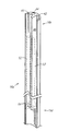
図3−5に示すように、栄養チューブ16は、管状部16a、近端部16b及び遠端部16cを含む。栄養チューブ16は、栄養チューブ16を患者の胃と空腸の中の様々な位置に配置することができるように、例えばシリコンのような、様々な種類の反復的な屈曲に耐え得る永続的かつ柔軟な素材から形成される。液体が胃と空腸に供給されるにつれて、遠端部16cは近端部16bに対して下方に配置される。近端部16bから始まって中央部16dまで延設される栄養チューブ16の部分の上に、栄養チューブ16は、胃ルーメン40、空腸ルーメン42、及び、放出口24が栄養チューブ16につながれた場合に胃ポート26、空腸ポート28及びバルーンポート30から形成されるチャネルと流体連結するバルーンルーメン44を含む。栄養チューブ16は、胃ルーメン40、空腸ルーメン42及びバルーンルーメン44が栄養チューブ16の上に一体的に提供されるように形成されてもよい。栄養チューブ16は種々なフレンチサイズで実施されてもよいが、本実施例における栄養チューブ16は14フレンチサイズである。
As shown in FIGS. 3-5, the feeding
図4において断面図として示すように、栄養チューブ16は、栄養チューブ16の通路を分離し、栄養チューブ16の近端部16bから中央部16dまで延設され、それによって胃ルーメン40と空腸ルーメン42とを形成する分離壁46を含む。分離壁46は、栄養チューブ16の通路の断面積を実質的に半分に分離するものであってもよく、また、バルーンルーメン44は、半分にされた断面積のうちの1つの一部であってもよい。ルーメン40、42及び44のそのような構成は、押出法(extrusion process)を用いて形成されてもよい。
As shown in cross-section in FIG. 4, the feeding
胃ルーメン40が空腸ルーメン42で流体連結しないように、胃ルーメン40は栄養チューブ16の中央部16dで分離される。これは、図4に示すように、接着剤64を用いて、例えば中央部16dで胃ルーメン40の端を裏込めしてもよい。このように、胃ルーメン40は栄養チューブ16の近端部16bから中央部16dに延設される。空腸ルーメン42は近端部16bから遠端部16cに延設され、そして、その断面積は近端部16bと中央部16dとの間よりも、中央部16dと遠端部16cとの間の方が大きい。中央部16dと遠端部16cとの間の空腸ルーメン42の断面積は、このように、胃ルーメン40の断面積と近端部16bと中央部16dとの間の空腸ルーメン42の断面積の合計より大きい。
The
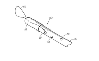
図2と6に示すように、栄養チューブ16は、胃ルーメン40の下方部分の外壁の上に形成される一つ以上の胃孔48と、空腸ルーメン42の下方部分の外側に位置する外壁に沿った一つ以上の空腸孔50とで構成される。その結果、栄養チューブ16の中と外への液体の伝送は、胃孔48と空腸孔50とを通じて可能となる。具体的には、栄養チューブ16と分離壁46とは、胃孔48と空腸孔50とがそれぞれ胃と空腸とに位置し、さらに、空腸ルーメン42が空腸と流体連結する際に胃ルーメン40が胃と流体連結するような長さに構成される。
As shown in FIGS. 2 and 6, the feeding
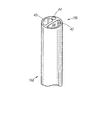
本実施例において、バルーン14はその常態としては円筒状であって拡張可能な構造であってもよく、栄養チューブ16の上に配置されてもよい。バルーン14の長手方向の端部は、例えば、閉鎖空間が長手方向の端部の間に形成されるように接着することによって、近端部16b付近の栄養チューブ16の外側に固定される。バルーンルーメン44の外側に対する栄養チューブ16の外壁は、それによってバルーンルーメン44とバルーン14との間を流体連結させている一つ以上のバルーン孔を備える。バルーンルーメン44は、バルーン14の閉鎖空間につながっているバルーン孔の下方に分離されてもよい。その結果、バルーンポート30に例えば空気または水のような外部の流体を供給することによって、図2に模型的に示すように、バルーン14をふくらませることができる。
In this embodiment, the
さらに、G−Jフィーディング装置10はワイヤ52(図1)のような補強要素を含んでもよく、それはバルーンルーメン44または胃ルーメン44の下方側に挿入され、胃ルーメン40に沿って部分的に延設されてもよい。図4に模型的に示される補強要素52は可鍛性を有するが、管状部の一部を屈曲しにくくさせるために、金属のような柔軟性と剛性とを備える素材で形成されてもよい。補強要素52は、中央部16d付近から遠端部16dの方向に、例えばバルーン14の下方の栄養チューブ16の一部と中央部16dとの間に延設されてもよい。補強要素52は小腸へのよりまっすぐな注入を可能にし、患者の身体から栄養チューブ16が押し戻される可能性を減少させる。補強要素52は、バルーン孔の下方にバルーンルーメン14を分離するために用いられてもよい。
Further, the GJ feeding device 10 may include a reinforcing element such as a wire 52 (FIG. 1), which is inserted below the
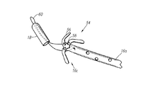
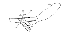
図7−8に示すように、遠端部16cは開放されており、デフォルト形状として管状部16aの直径より大きな形状を有する変形可能部54を含む。変形可能部54はそのデフォルト形状から変形可能であり、デフォルト形状では外側のフレア方向(flared orientation)に向かって管状部16aから延設される一つ以上のアーム56であってもよい。アーム56は管状部16aと一体的に形成されてもよく、又は栄養チューブ16の遠端部16cに任意の方法で接着されてもよい。アーム56にフレア方向を与え、アーム56に当該方向へのバイアスをかけるために、遠端部16cは、栄養チューブ16の内面の上で管状部16aとアーム56とのインタフェースに形成されるビード(bead)58を含んでもよい。このように、栄養チューブ16の柔軟性によって、アーム56を異なる位置に配置し、デフォルトの位置に戻すために変形させることができる。ビード58は、栄養チューブ16の内面の上にシリコンを塗布することによって形成されてもよい。変形可能部54は、多様な方向に形成されてもよい。例えば、アーム56は外側に広がる形状であってもよく(図8)、又は、近端部16bに向かって後方に向かう傘のような構造であってもよい(図7)。ビード58を使用する代わりに、個別の部分を遠端部16cに取り付けることによって傘のような構成を用いてもよい。
As shown in FIGS. 7-8, the
開放された遠端部16cのデザインは、装置10に、変形状態と解放されたデフォルト形状との両方へのガイドワイヤ親和性を持たせる。特に、ガイドワイヤ(図示せず)を胃と空腸とに挿入したあと、栄養チューブ16をガイドワイヤに沿って滑動させ、ガイドワイヤを空腸ルーメン42に沿って延長させることによって、栄養チューブ16を患者の身体に挿入することができる。
The open
内視鏡のような器具を用いる縫合糸60のループによって遠端部16cを牽引することができるように、縫合糸60のループを遠端部16cに接続してもよい。しかしながら、栄養チューブ16は器具を使用することなく栄養チューブ16を瘻孔に押し込むことによって患者の身体に挿入されてもよい。
The loop of
さらに、図6に示すように、遠端部16cのサイズを縮減し、患者の身体、特に腸内での遠端部16cの移動を容易にするために、栄養チューブ16の遠端部16cにカプセル18が設置されてもよい。カプセル18は、例えば植物性セルロース(HPMC)のような体液との接触によって溶解する素材で形成されてもよい。縫合糸60のループをカプセル18を貫通させて広げ、さらに、縫合糸60のループを器具で牽引することができるようにするために、カプセル18は開口62を備えてもよい。栄養チューブ16を挿入するためにガイドワイヤを用いる場合、ガイドワイヤをカプセル18の上の開口62に通し、そして、栄養チューブ16をガイドワイヤに続いて押して挿入する。
Further, as shown in FIG. 6, to reduce the size of the
患者の身体に遠端部16cを挿入する前に、カプセル18が遠端部16cに配置され、そして、アーム56はカプセル18に適応した形状に変形する。その後、遠端部16cが患者の空腸に届くまで遠端部16cが患者の身体に挿入される。カプセル18は予め定められた時間の経過によって溶解し、アーム56はフレア方向に戻る。フレア方向のアーム56は、空腸の中での遠端部16cの変形を制限して、遠端部16cが空腸からはね返されることを防止する。
Prior to insertion of the
この特許請求の範囲に記載された発明の趣旨および範囲から逸脱しない限り、様々な修正変更が可能であることは当業者にとって明らかである。 It will be apparent to those skilled in the art that various modifications and variations can be made without departing from the spirit and scope of the invention as set forth in the claims below.
フィーディング装置 10
胃−空腸本体(G−J本体) 12
栄養チューブ 16
上部 20
下部 22
胃ポート 26
胃チャネル 27
空腸ポート 28
空腸チャネル 29
バルーンポート 30
胃ルーメン 40
空腸ルーメン 42
バルーンルーメン 44
Feeding device 10
Stomach-jejunum body (GJ body) 12
Claims (16)
近端部と遠端部を含み、前記近端部は変形可能なように前記胃−空腸本体の前記下部に接続している一体型栄養チューブとを含む胃−空腸(G−J)フィーディング装置であって、
前記一体型栄養チューブは、
前記胃チャネルと流体連結するように構成され、前記近端部から前記一体型栄養チューブの中央部に延設される胃ルーメンと、
前記空腸チャネルと流体連結するように構成され、前記近端部から前記遠端部に延設される空腸ルーメンと、
前記バルーンポートと流体連結するように構成されるバルーンルーメンとをさらに含み、
前記中央部と前記近端部との間の前記空腸ルーメンの断面積より、前記中央部と前記遠端部との間の前記空腸ルーメンの断面積のほうが大きいことを特徴とする胃−空腸(G−J)フィーディング装置。 A gastro-jejunum body comprising an upper portion, a lower portion and a balloon port, wherein the lower portion is configured to contact the patient's skin, the upper portion comprising a gastric port connected to the gastric channel and a jejunal port connected to the jejunal channel;
Gastro-jejunum (GJ) feeding including a proximal end and a distal end, the proximal end including an integral feeding tube connected to the lower portion of the stomach-jejunum body for deformation A device,
The integrated feeding tube is
A gastric lumen configured to fluidly connect with the gastric channel and extending from the proximal end to a central portion of the integrated feeding tube;
A jejunal lumen configured to fluidly connect with the jejunal channel and extending from the proximal end to the distal end;
A balloon lumen configured to be in fluid communication with the balloon port;
The gastro-jejunum, wherein the cross-sectional area of the jejunum lumen between the central portion and the distal end portion is larger than the cross-sectional area of the jejunal lumen between the central portion and the proximal end portion. GJ) Feeding device.
前記空腸ルーメンが前記一体型栄養チューブの外側と流体連結するための少なくとも1つの空腸孔と、
前記胃ルーメンが前記一体型栄養チューブの外側と流体連結するための少なくとも1つの胃孔とを更に含むことを特徴とする請求項1に記載の胃−空腸(G−J)フィーディング装置。 The integrated feeding tube is
At least one jejunal hole for fluid connection of the jejunum lumen with the outside of the integral feeding tube;
The gastric-jejunum (GJ) feeding device according to claim 1, wherein the gastric lumen further comprises at least one gastric hole for fluid communication with the outside of the integrated feeding tube.
前記中央部と前記バルーンとの間に延設される補強要素とをさらに含むことを特徴とする請求項10に記載の胃−空腸(G−J)フィーディング装置。 A balloon secured over the integral feeding tube;
The gastric-jejunum (GJ) feeding device according to claim 10, further comprising a reinforcing element extending between the central portion and the balloon.
管状部と、
患者の身体の外に位置するように構成される前記近端部と、
患者の身体に挿入され、デフォルト形状において前記管状部の直径より大きな幅を有する変形可能部を備えるように構成される前記遠端部と、
前記変形可能部を覆い、変形可能にするために前記遠端部の上に配置されるように構成されるカプセルとをさらに含み、
前記カプセルは、体液との接触によって溶解するように構成され、前記変形可能部は、前記カプセルが溶解するとデフォルト形状に戻るように構成されることを特徴とする請求項1に記載の胃−空腸(G−J)フィーディング装置。 The integrated feeding tube is
A tubular section;
Wherein a proximal end configured to be located outside the patient's body,
Is inserted into the body of a patient, said distal end configured in the default configuration comprises a deformable portion having a greater width than the diameter of said tubular portion,
Covering the deformable portion further includes a capsule configured to be disposed on the distal end in order to allow deformation,
The gastro-jejunum of claim 1 , wherein the capsule is configured to dissolve upon contact with a body fluid, and the deformable portion is configured to return to a default shape when the capsule is dissolved. (GJ) Feeding device.
前記アームと前記胃−空腸本体とのインタフェースに配置され、前記アームに外側のフレア方向を与えるように構成されるビードを更に含むことを特徴とする請求項13に記載の胃−空腸(G−J)フィーディング装置。 The integrated feeding tube is
The gastric-jejunum (G- ) of claim 13, further comprising a bead disposed at an interface between the arm and the stomach-jejunum body and configured to impart an outward flare direction to the arm. J) Feeding device .
前記遠端部付近に縫合糸のループをさらに含み、前記遠端部は、前記縫合糸のループを牽引することによって患者の身体に挿入されるように構成されることを特徴とする請求項12に記載の胃−空腸(G−J)フィーディング装置。 The integrated feeding tube is
13. The suture further comprising a suture loop near the distal end, wherein the distal end is configured to be inserted into a patient's body by pulling the suture loop. A gastro-jejunum (GJ) feeding device according to claim 1 .
Applications Claiming Priority (2)
| Application Number | Priority Date | Filing Date | Title |
|---|---|---|---|
| US13/024,003 US9095502B2 (en) | 2011-02-09 | 2011-02-09 | Low profile G-J feeding tube |
| US13/024,003 | 2011-02-09 |
Publications (3)
| Publication Number | Publication Date |
|---|---|
| JP2012166023A JP2012166023A (en) | 2012-09-06 |
| JP2012166023A5 JP2012166023A5 (en) | 2015-03-26 |
| JP5907746B2 true JP5907746B2 (en) | 2016-04-26 |
Family
ID=45562199
Family Applications (1)
| Application Number | Title | Priority Date | Filing Date |
|---|---|---|---|
| JP2012025439A Active JP5907746B2 (en) | 2011-02-09 | 2012-02-08 | Low profile GJ feeding device |
Country Status (3)
| Country | Link |
|---|---|
| US (1) | US9095502B2 (en) |
| EP (1) | EP2486911B1 (en) |
| JP (1) | JP5907746B2 (en) |
Families Citing this family (6)
| Publication number | Priority date | Publication date | Assignee | Title |
|---|---|---|---|---|
| BR112015015121B1 (en) * | 2012-12-23 | 2021-03-09 | Applied Medical Technology, Inc. | torsion resistant tube |
| US9427378B2 (en) * | 2013-04-30 | 2016-08-30 | Avent, Inc. | Gastric jejunal tube with an enlarged jejunal lumen |
| US9301903B2 (en) * | 2014-03-31 | 2016-04-05 | Gerald Moss | Multi-lumen catheter |
| EP3402454A2 (en) * | 2016-01-15 | 2018-11-21 | Neomed, Inc. | Large bore enteral connector |
| US10952931B2 (en) * | 2017-11-03 | 2021-03-23 | Children's Hospital Medical Center Of Akron | Exchangeable balloon gastrojejunostomy tube |
| US11471381B2 (en) * | 2018-04-30 | 2022-10-18 | Applied Medical Technology, Inc. | Gastric jejunal feeding tube devices for gastric jejunal feeding of an infant or child |
Family Cites Families (29)
| Publication number | Priority date | Publication date | Assignee | Title |
|---|---|---|---|---|
| US4393873A (en) * | 1980-03-10 | 1983-07-19 | Nawash Michael S | Gastrostomy and other percutaneous transport tubes |
| US4666433A (en) | 1984-11-05 | 1987-05-19 | Medical Innovations Corporation | Gastrostomy feeding device |
| DE3610419A1 (en) | 1986-03-27 | 1987-10-01 | Pfrimmer Viggo Gmbh Co Kg | CATHETER FOR PERCUTANEOUS GASTROSTOMY |
| DE3731590C1 (en) | 1987-09-19 | 1988-07-21 | Braun Melsungen Ag | Medical probe |
| US5057091A (en) | 1989-07-31 | 1991-10-15 | Corpak, Inc. | Enteral feeding tube with a flexible bolus and feeding bolus |
| US4986810A (en) | 1989-09-01 | 1991-01-22 | Neal Semrad | Toggle catheter |
| US5152756A (en) | 1990-01-24 | 1992-10-06 | Corpak, Inc. | Distal gripping tip for enteral feeding tube |
| US5405341A (en) * | 1993-06-03 | 1995-04-11 | Med-Pro Design, Inc. | Catheter with multiple lumens |
| US5486159A (en) | 1993-10-01 | 1996-01-23 | Mahurkar; Sakharam D. | Multiple-lumen catheter |
| DE4334722A1 (en) * | 1993-10-12 | 1995-04-13 | Bosch Gmbh Robert | Electrical contacting of a light source |
| US5527280A (en) | 1995-03-29 | 1996-06-18 | The Children's Seashore House | Multi-lumen enteral feeding and medicating device |
| US6547761B2 (en) * | 2000-01-07 | 2003-04-15 | Scimed Life Systems, Inc. | Drainage catheter |
| US6352544B1 (en) * | 2000-02-22 | 2002-03-05 | Gregory A. Spitz | Apparatus and methods for removing veins |
| US6997931B2 (en) * | 2001-02-02 | 2006-02-14 | Lsi Solutions, Inc. | System for endoscopic suturing |
| US6673058B2 (en) * | 2001-06-20 | 2004-01-06 | Scimed Life Systems, Inc. | Temporary dilating tip for gastro-intestinal tubes |
| US7048722B2 (en) | 2001-11-16 | 2006-05-23 | Radius International Limited Partnership | Catheter |
| US6896665B2 (en) | 2001-12-10 | 2005-05-24 | Applied Medical Research | Gastrostomy device package and method of assembly |
| WO2003088920A2 (en) | 2002-04-22 | 2003-10-30 | The Children's Hospital Of Philadelphia | Low profile combination device for gastrostomy or jejunostomy applications having anti-granuloma formation characteristics |
| US20030225392A1 (en) | 2002-05-31 | 2003-12-04 | Kimberly-Clark Worldwide, Inc. | Low profile transpyloric jejunostomy system and method to enable |
| US20030225369A1 (en) | 2002-05-31 | 2003-12-04 | Kimberly-Clark Worldwide, Inc. | Low profile transpyloric jejunostomy system |
| US20030225393A1 (en) | 2002-05-31 | 2003-12-04 | Kimberly-Clark Worldwide, Inc. | Low profile transpyloric jejunostomy system and method to enable |
| US7419479B2 (en) | 2002-11-15 | 2008-09-02 | Radius International Limited Partnership | Catheter |
| US20050124932A1 (en) | 2003-12-05 | 2005-06-09 | Kimberly-Clark Worldwide, Inc. | Venting catheter |
| US20050124935A1 (en) | 2003-12-05 | 2005-06-09 | Kimberly-Clark Worldwide, Inc. | Venting adapter for feeding device |
| US7582072B2 (en) * | 2004-09-09 | 2009-09-01 | Kimberly-Clark Worldwide, Inc. | Artificial stoma and method of use |
| US7220253B2 (en) | 2004-12-02 | 2007-05-22 | Chek-Med Systems, Inc. | Gastrojejunal feeding tube |
| US8016785B2 (en) | 2004-12-02 | 2011-09-13 | Chek-Med Systems, Inc. | Gastrojejunal feeding tube |
| US7699818B2 (en) * | 2005-02-08 | 2010-04-20 | Paul J. Gilbert | Insertion system and methods for nasogastric tubes |
| US20070255222A1 (en) | 2006-03-27 | 2007-11-01 | Changqing Li | Catheter assembly including internal bolster |
-
2011
- 2011-02-09 US US13/024,003 patent/US9095502B2/en active Active
-
2012
- 2012-02-07 EP EP12154151.0A patent/EP2486911B1/en active Active
- 2012-02-08 JP JP2012025439A patent/JP5907746B2/en active Active
Also Published As
| Publication number | Publication date |
|---|---|
| EP2486911A2 (en) | 2012-08-15 |
| EP2486911B1 (en) | 2016-06-22 |
| US20120203171A1 (en) | 2012-08-09 |
| US9095502B2 (en) | 2015-08-04 |
| JP2012166023A (en) | 2012-09-06 |
| EP2486911A3 (en) | 2013-09-04 |
Similar Documents
| Publication | Publication Date | Title |
|---|---|---|
| JP5907746B2 (en) | Low profile GJ feeding device | |
| JP5184512B2 (en) | Supply device, bolster apparatus, and method for producing the same | |
| EP1140272B1 (en) | Gastric balloon catheter with improved balloon orientation | |
| US9597263B2 (en) | Fluid and nutrition delivery device and method of use | |
| ES2756324T3 (en) | Tear-away introducer sheath with hemostasis valve | |
| JP4599170B2 (en) | Catheter with integral part | |
| JP3683812B2 (en) | Retention balloon for body access tube assembly | |
| JP4772042B2 (en) | Retaining device for medical components | |
| JP2005527333A (en) | Low contour shape transpyloric jejunostomy system | |
| EP2301512B1 (en) | Tube for gastrointestinal tract | |
| JP2006507894A (en) | Catheter having a balloon portion mounted inverted | |
| JP2007502143A (en) | Catheter attached with balloon member retracted | |
| US6960199B2 (en) | Method for feeding with a tube | |
| JP4119904B2 (en) | Medical catheter fixture | |
| JP4021421B2 (en) | Body access port | |
| BR112020015968A2 (en) | PIPE ASSEMBLY AND DISSOLuble TIP | |
| JP2009125251A (en) | Catheter and catheter kit | |
| JP7210405B2 (en) | catheter | |
| JP6410529B2 (en) | Transgastric jejunum tube | |
| JP5229029B2 (en) | Fistula catheter | |
| JP2005288185A (en) | Catheter inserted in enteron and retaining method thereof | |
| JP2011078456A (en) | Nutrition catheter | |
| MXPA01006878A (en) | Gastric balloon catheter with improved balloon orientation | |
| JP2013070812A (en) | Fistula catheter | |
| SE521563C2 (en) | Patient food intake reducing device, comprises gastric band with end fasteners and flexible wall forming expandable lume |
Legal Events
| Date | Code | Title | Description |
|---|---|---|---|
| A521 | Request for written amendment filed |
Free format text: JAPANESE INTERMEDIATE CODE: A523 Effective date: 20150203 |
|
| A621 | Written request for application examination |
Free format text: JAPANESE INTERMEDIATE CODE: A621 Effective date: 20150203 |
|
| A131 | Notification of reasons for refusal |
Free format text: JAPANESE INTERMEDIATE CODE: A131 Effective date: 20151222 |
|
| A521 | Request for written amendment filed |
Free format text: JAPANESE INTERMEDIATE CODE: A523 Effective date: 20160215 |
|
| TRDD | Decision of grant or rejection written | ||
| A01 | Written decision to grant a patent or to grant a registration (utility model) |
Free format text: JAPANESE INTERMEDIATE CODE: A01 Effective date: 20160308 |
|
| A61 | First payment of annual fees (during grant procedure) |
Free format text: JAPANESE INTERMEDIATE CODE: A61 Effective date: 20160322 |
|
| R150 | Certificate of patent or registration of utility model |
Ref document number: 5907746 Country of ref document: JP Free format text: JAPANESE INTERMEDIATE CODE: R150 |
|
| R250 | Receipt of annual fees |
Free format text: JAPANESE INTERMEDIATE CODE: R250 |
|
| R250 | Receipt of annual fees |
Free format text: JAPANESE INTERMEDIATE CODE: R250 |
|
| R250 | Receipt of annual fees |
Free format text: JAPANESE INTERMEDIATE CODE: R250 |
|
| R250 | Receipt of annual fees |
Free format text: JAPANESE INTERMEDIATE CODE: R250 |
|
| R250 | Receipt of annual fees |
Free format text: JAPANESE INTERMEDIATE CODE: R250 |
|
| R250 | Receipt of annual fees |
Free format text: JAPANESE INTERMEDIATE CODE: R250 |