JP5904252B2 - Position detection device - Google Patents
Position detection device Download PDFInfo
- Publication number
- JP5904252B2 JP5904252B2 JP2014207126A JP2014207126A JP5904252B2 JP 5904252 B2 JP5904252 B2 JP 5904252B2 JP 2014207126 A JP2014207126 A JP 2014207126A JP 2014207126 A JP2014207126 A JP 2014207126A JP 5904252 B2 JP5904252 B2 JP 5904252B2
- Authority
- JP
- Japan
- Prior art keywords
- magnetic flux
- transmission member
- flux transmission
- range
- yoke
- Prior art date
- Legal status (The legal status is an assumption and is not a legal conclusion. Google has not performed a legal analysis and makes no representation as to the accuracy of the status listed.)
- Active
Links
Images


Classifications
-
- G—PHYSICS
- G01—MEASURING; TESTING
- G01D—MEASURING NOT SPECIALLY ADAPTED FOR A SPECIFIC VARIABLE; ARRANGEMENTS FOR MEASURING TWO OR MORE VARIABLES NOT COVERED IN A SINGLE OTHER SUBCLASS; TARIFF METERING APPARATUS; MEASURING OR TESTING NOT OTHERWISE PROVIDED FOR
- G01D5/00—Mechanical means for transferring the output of a sensing member; Means for converting the output of a sensing member to another variable where the form or nature of the sensing member does not constrain the means for converting; Transducers not specially adapted for a specific variable
- G01D5/12—Mechanical means for transferring the output of a sensing member; Means for converting the output of a sensing member to another variable where the form or nature of the sensing member does not constrain the means for converting; Transducers not specially adapted for a specific variable using electric or magnetic means
- G01D5/14—Mechanical means for transferring the output of a sensing member; Means for converting the output of a sensing member to another variable where the form or nature of the sensing member does not constrain the means for converting; Transducers not specially adapted for a specific variable using electric or magnetic means influencing the magnitude of a current or voltage
- G01D5/142—Mechanical means for transferring the output of a sensing member; Means for converting the output of a sensing member to another variable where the form or nature of the sensing member does not constrain the means for converting; Transducers not specially adapted for a specific variable using electric or magnetic means influencing the magnitude of a current or voltage using Hall-effect devices
- G01D5/145—Mechanical means for transferring the output of a sensing member; Means for converting the output of a sensing member to another variable where the form or nature of the sensing member does not constrain the means for converting; Transducers not specially adapted for a specific variable using electric or magnetic means influencing the magnitude of a current or voltage using Hall-effect devices influenced by the relative movement between the Hall device and magnetic fields
Landscapes
- Physics & Mathematics (AREA)
- General Physics & Mathematics (AREA)
- Transmission And Conversion Of Sensor Element Output (AREA)
Description
本発明は、検出対象の位置を検出する位置検出装置に関する。 The present invention relates to a position detection device that detects the position of a detection target.
基準部材に対し相対移動する検出対象の位置を検出可能な磁気式の位置検出装置が知られている。この種の位置検出装置は、閉磁気回路を形成する2つの磁石および2つのヨーク(磁束伝達部材)と、閉磁気回路の内側に設けられるホール素子などの磁束密度検出手段とを備える。例えば、磁石およびヨークは検出対象に設けられ、磁束密度検出手段は基準部材に設けられる。磁束密度検出手段を通過する磁束の密度は、ヨークに対する磁束密度検出手段の位置に応じて変化する。位置検出装置は、磁束密度検出手段を通過する磁束の密度に基づき検出対象の位置を検出する。 2. Description of the Related Art A magnetic position detection device that can detect the position of a detection target that moves relative to a reference member is known. This type of position detection device includes two magnets and two yokes (magnetic flux transmission members) forming a closed magnetic circuit, and magnetic flux density detection means such as a Hall element provided inside the closed magnetic circuit. For example, the magnet and the yoke are provided on the detection target, and the magnetic flux density detection means is provided on the reference member. The density of the magnetic flux passing through the magnetic flux density detecting means changes according to the position of the magnetic flux density detecting means with respect to the yoke. The position detection device detects the position of the detection target based on the density of the magnetic flux passing through the magnetic flux density detection means.
例えば特許文献1に開示された位置検出装置は、基準部材に対し回転する検出対象の回転角度を検出するものであって、2つのヨークが検出対象の回転方向に沿って並行して延びるように形成されている。2つのヨークを対向方向に見たとき、各ヨークの幅は、回転方向の両端部から中央にかけて漸次小さくなっている。これにより、2つのヨーク間の漏洩磁束が増え、磁束密度検出手段の出力信号の直線性を良好にすること、すなわち、検出対象の回転角度と磁束密度検出手段の出力電圧との関係を線形関係に近づけることが可能である。
For example, the position detection device disclosed in
ところで、特許文献1では、ヨークのうち回転方向の中央部は、回転方向の両端部と比べて幅が小さいため、外乱磁場の影響を受けやすい。そのため、外乱磁場の影響を回避するという観点から、ヨークの中央部の幅は、外乱耐性が確保可能な所定の幅よりも小さくすることができない。したがって、2つのヨーク間の漏洩磁束を増やすには限界がある。また、良好な直線性を狙って設計したヨークの中央部の幅が、外乱耐性が確保可能な所定の幅より小さい場合、外乱耐性を確保するため、中央部の幅を変更して直線性を犠牲にしなければならない。
By the way, in
また、ヨークの幅が漸次的に変化するように設計すること、および、このようなヨークを製造することは困難である。
本発明は、上述の点に鑑みてなされたものであり、その目的は、磁束伝達部材の中央部の外乱耐性の低下を抑制しつつ磁束密度検出手段の出力信号の直線性を向上させることができ、また磁束伝達部材の設計および製造が容易な位置検出装置を提供することである。
It is also difficult to design the yoke width to change gradually and to manufacture such a yoke.
The present invention has been made in view of the above-described points, and its object is to improve the linearity of the output signal of the magnetic flux density detection means while suppressing a decrease in disturbance resistance at the center of the magnetic flux transmission member. It is another object of the present invention to provide a position detection device which can be easily designed and manufactured.
本発明は、基準部材に対し相対移動する検出対象の位置を検出可能な位置検出装置であって、第1磁束伝達部材、第2磁束伝達部材、第1磁束発生手段、第2磁束発生手段および磁束密度検出手段を備えている。 The present invention is a position detection device capable of detecting the position of a detection target that moves relative to a reference member, and includes a first magnetic flux transmission member, a second magnetic flux transmission member, a first magnetic flux generation means, a second magnetic flux generation means, and Magnetic flux density detection means is provided.
第1磁束伝達部材は、検出対象の移動方向へ沿うように延びている。第2磁束伝達部材は、第1磁束伝達部材と並行して前記移動方向へ沿うように延び、第1磁束伝達部材と共に基準部材および検出対象の一方に設けられる。第1磁束発生手段は、第1磁束伝達部材および第2磁束伝達部材のうち前記移動方向の一端部同士の間に設けられている。第2磁束発生手段は、第1磁束伝達部材および第2磁束伝達部材のうち前記移動方向の他端部同士の間に設けられている。磁束密度検出手段は、第1磁束伝達部材と第2磁束伝達部材との間の隙間に位置し、基準部材および検出対象の他方に設けられ、当該磁束密度検出手段を通過する磁束の密度に応じた信号を出力する。 The first magnetic flux transmission member extends along the moving direction of the detection target. The second magnetic flux transmission member extends along the moving direction in parallel with the first magnetic flux transmission member, and is provided together with the first magnetic flux transmission member on one of the reference member and the detection target. The first magnetic flux generation means is provided between one end portions in the moving direction of the first magnetic flux transmission member and the second magnetic flux transmission member. The second magnetic flux generation means is provided between the other end portions in the moving direction of the first magnetic flux transmission member and the second magnetic flux transmission member. The magnetic flux density detection means is located in the gap between the first magnetic flux transmission member and the second magnetic flux transmission member, and is provided on the other of the reference member and the detection target, according to the density of the magnetic flux passing through the magnetic flux density detection means. Output the signal.
特に本発明は、第1磁束伝達部材が第1中間部を有していること、および、第2磁束伝達部材が第2中間部を有していることを特徴としている。第1磁束伝達部材の第1中間部は、当該第1磁束伝達部材の一端部と他端部との間に位置し、第1磁束伝達部材と第2磁束伝達部材とが対向する方向である対向方向に見たときの幅が一端部および他端部よりも小さく且つ前記移動方向で一定である。第2磁束伝達部材の第2中間部は、当該第2磁束伝達部材の一端部と他端部との間に位置し、対向方向に見たときの幅が一端部および他端部よりも小さく且つ前記移動方向で一定である。 In particular, the present invention is characterized in that the first magnetic flux transmission member has a first intermediate portion and the second magnetic flux transmission member has a second intermediate portion. The first intermediate portion of the first magnetic flux transmission member is located between one end and the other end of the first magnetic flux transmission member, and is a direction in which the first magnetic flux transmission member and the second magnetic flux transmission member face each other. The width when viewed in the facing direction is smaller than the one end and the other end and is constant in the moving direction. The second intermediate portion of the second magnetic flux transmission member is located between the one end portion and the other end portion of the second magnetic flux transmission member, and the width when viewed in the facing direction is smaller than the one end portion and the other end portion. And it is constant in the moving direction.
このように構成することで、磁束伝達部材の中央部の幅を外乱耐性が確保可能な所定の幅に設計する場合、磁束伝達部材の幅を移動方向の両端部から中央にかけて漸次小さくする従来技術のものと比べて、各磁束伝達部材間の漏洩磁束が増える。各磁束伝達部材間の漏洩磁束が増えることによって、(1)磁束密度検出手段が検出する磁束密度に対して外乱磁場が影響する割合が小さくなるので、外乱磁場に対する耐性が向上し、また、(2)磁束密度検出手段による磁電変換における信号増幅を小さく設定することができるので、電源ノイズ等の増幅影響が小さくなり、磁束密度検出手段の出力電圧が理想に対して変動しにくい。したがって、本発明によれば、磁束伝達部材の中央部の外乱耐性の低下を抑制しつつ磁束密度検出手段の出力信号の直線性を向上させることができる。 By configuring in this way, when designing the width of the central portion of the magnetic flux transmission member to a predetermined width that can ensure disturbance resistance, the conventional technology of gradually reducing the width of the magnetic flux transmission member from both ends of the moving direction to the center As compared with the above, the leakage magnetic flux between the magnetic flux transmission members increases. By increasing the leakage magnetic flux between the magnetic flux transmission members, (1) since the ratio of the disturbance magnetic field to the magnetic flux density detected by the magnetic flux density detection means is reduced, the resistance to the disturbance magnetic field is improved, and ( 2) Since the signal amplification in the magnetoelectric conversion by the magnetic flux density detecting means can be set small, the influence of amplification such as power supply noise is reduced, and the output voltage of the magnetic flux density detecting means is less likely to fluctuate from the ideal. Therefore, according to the present invention, it is possible to improve the linearity of the output signal of the magnetic flux density detection means while suppressing a decrease in disturbance tolerance at the center of the magnetic flux transmission member.
また、本発明では、磁束伝達部材の中間部の幅は移動方向で一定である。したがって、磁束伝達部材は、上述の従来技術のものと比べて形状が単純なものとなり、設計および製造が容易となる。 In the present invention, the width of the intermediate portion of the magnetic flux transmission member is constant in the moving direction. Therefore, the magnetic flux transmission member has a simple shape as compared with the above-described prior art, and is easy to design and manufacture.
以下、本発明の複数の実施形態を図面に基づき説明する。実施形態同士で実質的に同一の構成には同一の符号を付して説明を省略する。
<第1実施形態>
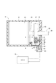
本発明の第1実施形態による位置検出装置は、図1に示す回転駆動装置に設けられている。回転駆動装置80は、図示しないウェイストゲートバルブを開閉駆動するために用いられている。ウェイストゲートバルブは、ターボチャージャーによる過給エンジンにおいて、排気ガスの一部を分流させることによりタービンへの流入量を調節するバルブである。
Hereinafter, a plurality of embodiments of the present invention will be described with reference to the drawings. In the embodiments, substantially the same components are denoted by the same reference numerals and description thereof is omitted.
<First Embodiment>
The position detection device according to the first embodiment of the present invention is provided in the rotary drive device shown in FIG. The
(回転駆動装置)
先ず、回転駆動装置80の構成について図1を参照して説明する。回転駆動装置80は、ハウジング81、ケース82、モータ85、回転体87、出力軸92および位置検出装置5を備えている。
ハウジング81は、モータ収容室を有し、車体または車体に取り付けられた部材に固定される。
(Rotary drive device)
First, the configuration of the
The
ケース82は、ハウジング81の開口部に固定されているカバー部83と、カバー部83から外側に突き出すコネクタ部84とを形成している。
モータ85は、ハウジング81内に設けられており、パワー端子93を介して電子制御装置95に電気的に接続される。モータ85は、電子制御装置95から電力が供給されるとモータ軸86を回転させる。
The
The motor 85 is provided in the
回転体87は、モータ軸86と同軸上に設けられている円板部材であり、軸心96から外れた位置で周方向へ延びる円弧状の通孔88を有している。回転体87は、モータ軸86に回転伝達可能に連結されている。
出力軸92は、モータ軸86と同軸上に設けられ、ケース82により回転可能に支持され、回転体87に回転伝達可能に連結されている。出力軸92は、図示しないリンク機構を介してウェイストゲートバルブに連結される。
The rotating
The
位置検出装置5は、軸方向において回転体87と一致し且つ径方向において軸心96から外れた位置に設けられ、ケース82に対する回転体87の相対的な回転角度を検出可能である。ケース82は、特許請求の範囲に記載の「基準部材」に相当し、回転体87は、特許請求の範囲に記載の「検出対象」に相当する。位置検出装置5は、信号端子94を介して電子制御装置95に電気的に接続される。
The
上記のように構成された回転駆動装置80は、電子制御装置95から電力が供給されると、モータ85により出力軸92を回転させつつ、回転体87の回転角度に応じた電圧を位置検出装置5から電子制御装置95に出力する。電子制御装置95は、位置検出装置5の出力電圧に基づいてモータ85を駆動し、回転体87の回転角度が目標値に一致するようにフィードバック制御を実行する。
When the electric power is supplied from the
(位置検出装置の基本構成)
次に、位置検出装置5の基本構成について図1、図2を参照して説明する。
位置検出装置5は、第1ヨーク10、第2ヨーク15、第1磁石25、第2磁石26および短絡磁路部30を備えている。
(Basic configuration of position detector)
Next, the basic configuration of the
The
第1ヨーク10は、磁性材料から構成され、回転体87の通孔88のうち径方向外側の内壁89に沿うように回転体87の回転方向へ延びている。第1ヨーク10は、回転体87に固定されており、特許請求の範囲に記載の「第1磁束伝達部材」に相当する。
以下、「回転方向」とは、回転体87が回転する方向という意味で使用する。回転方向は、特許請求の範囲に記載の「移動方向」に相当する。
The
Hereinafter, the “rotating direction” is used to mean a direction in which the
第2ヨーク15は、磁性材料から構成され、回転体87の通孔88のうち径方向内側の内壁91に沿うように第1ヨーク10と並行して回転方向へ延びている。第2ヨーク15は、回転体87に固定されており、特許請求の範囲に記載の「第2磁束伝達部材」に相当する。
The
第1磁石25は、第1ヨーク10の一端部11と第2ヨーク15の一端部16との間に設けられており、特許請求の範囲に記載の「第1磁束発生手段」に相当する。第1磁石25は、着磁方向が各ヨークの対向方向と一致し、N極が径方向外側に位置するとともにS極が径方向内側に位置するように設けられている。以下、「対向方向」とは、第1ヨーク10と第2ヨーク15とが対向する方向という意味で使用する。本実施形態では、対向方向は、回転体87の径方向、すなわち、回転体87の回転軸心96に直交する方向と一致する。
The
第2磁石26は、第1ヨーク10の他端部12と第2ヨーク15の他端部17との間に設けられており、特許請求の範囲に記載の「第2磁束発生手段」に相当する。本実施形態では、第2磁石26は、着磁方向が対向方向と一致し、N極が径方向内側に位置するとともにS極が径方向外側に位置するように設けられている。
The
第1ヨーク10および第2ヨーク15は、第1磁石25と第2磁石26とをつないでいる磁気回路構成部材であり、第1磁石25および第2磁石26と共に閉磁気回路を形成している。第1ヨーク10と第2ヨーク15との間には、回転方向へ延びる弧状の隙間20が区画形成されている。
The
第1磁石25のN極から出る磁束には、第1ヨーク10を通って第2磁石26のS極に流れる還流磁束と、第1ヨーク10から隙間20を通って第2ヨーク15に流れる漏洩磁束と、第1ヨーク10および第2ヨーク15を通ることなく隙間20を通って第1磁石25のS極に流れる直通磁束とが含まれる。
第2磁石26のN極から出る磁束には、第2ヨーク15を通って第1磁石25のS極に流れる還流磁束と、第2ヨーク15から隙間20を通って第1ヨーク10に流れる漏洩磁束と、第1ヨーク10および第2ヨーク15を通ることなく隙間20を通って第2磁石26のS極に流れる直通磁束とが含まれる。
The magnetic flux emitted from the north pole of the
The magnetic flux emitted from the N pole of the
短絡磁路部30は、ホールIC31と、当該ホールIC31をモールドしているモールド部材32とを有している。モールド部材32は、ケース82に固定されている。ホールIC31は、ホール素子33を有している。ホール素子33は、ホール効果を利用した磁電変換素子であって、感磁面を通過する磁束の密度に応じた電圧を出力するものであり、特許請求の範囲に記載の「磁束密度検出手段」に相当する。ホール素子33を通過する磁束の密度は、回転体87が回転してホール素子33と閉磁気回路との相対位置が変化することに伴い増減する。
The short-circuit
(位置検出装置の特徴構成)
次に、位置検出装置5の特徴構成について図2〜図5を参照して説明する。
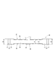
図2、図3に示すように、第1ヨーク10は、一端部11と他端部12との間に中間部35を有している。第1ヨーク10を対向方向に見たとき、中間部35の幅b1は、一端部11および他端部12の幅b2よりも小さく、且つ、移動方向で一定である。中間部35は、特許請求の範囲に記載の「第1中間部」に相当する。
(Characteristic configuration of position detector)
Next, a characteristic configuration of the
As shown in FIGS. 2 and 3, the
第2ヨーク15は、一端部16と他端部17との間に中間部36を有している。第2ヨーク15を対向方向に見たとき、中間部36の幅b1は、一端部16および他端部17の幅b2よりも小さく、且つ、移動方向で一定である。中間部36は、特許請求の範囲に記載の「第2中間部」に相当する。
The
図2に示すように、本実施形態では、回転方向において第1ヨーク10の中間部35が占める範囲は、第2ヨーク15の中間部36が占める範囲と大きさ及び範囲が一致する。以下、上記範囲を「中間範囲θb」と記載する。回転体87の回転角度を検出する範囲を検出範囲θfsとすると、中間範囲θbは、検出範囲θfsよりも大きく且つ検出範囲θfsを全て含むように設定されている。
As shown in FIG. 2, in the present embodiment, the range occupied by the
図4には、直交座標系において、回転体87の回転角度θと、ホール素子33を通過する磁束の密度Bとの関係を示す特性線L1を示している。回転角度θは、特許請求の範囲に記載の「検出対象の位置」に相当する。また、図5には、回転角度θとホール素子33の出力電圧Vとの関係を示す特性線L2を示している。出力電圧Vは、特許請求の範囲に記載の「出力信号」に相当する。
FIG. 4 shows a characteristic line L1 indicating the relationship between the rotation angle θ of the
図4において、検出磁束密度Bが0となる特性線L1上の座標を0点P0L1とする。また、図5において、図4の0点P0L1に対応する特性線L2上の座標を0点P0L2とし、当該0点P0L2を通り且つ傾きが理想傾きaである理想直線L3を二点鎖線で示している。
本実施形態では、中間範囲θbは、検出範囲θfsにおける特性線L2と理想直線L3との出力電圧差が所定値V1以内となるように設定されている。所定値V1は、必要精度を考慮して決定される値である。
In FIG. 4, a coordinate on the characteristic line L1 where the detected magnetic flux density B is 0 is defined as a zero point P0 L1 . Further, in FIG. 5, the coordinates on the characteristic line L2 corresponding to the zero point P0 L1 in FIG. 4 are defined as the zero point P0 L2, and two ideal straight lines L3 passing through the zero point P0 L2 and having the ideal inclination a are two points. Shown with a chain line.
In the present embodiment, the intermediate range θb is set such that the output voltage difference between the characteristic line L2 and the ideal straight line L3 in the detection range θfs is within a predetermined value V1. The predetermined value V1 is a value determined in consideration of necessary accuracy.
具体的には、中間範囲θbは、次の(A)、(B)を順に経て設定されている。以下、中間範囲θbのうち、検出範囲θfsと重ならない範囲の一方を第1余剰範囲θs1とし、他方を第2余剰範囲θs2とする。
(A)回転体87の作動角度範囲に基づき検出範囲θfsが決定される。
(B)一端部11、27と中間部35、36との接続箇所、および、他端部12、28と中間部35、36との接続箇所は、幅が急激に変化する。そのため、図5に示すように、特性線L2の傾きは、中間範囲θbの両端部分で比較的大きく変化する。したがって、検出範囲θfsにおける特性線L2の直線性は、第1余剰範囲θs1および第2余剰範囲θs2を可及的に大きくすることによって向上する。本実施形態では、第1余剰角度θs1および第2余剰角度θs2は、検出範囲θfsにおける特性線L2と理想直線L3との出力電圧差が所定値V1以内となるように決定される。
Specifically, the intermediate range θb is set through the following (A) and (B) in order. Hereinafter, in the intermediate range θb, one of the ranges that does not overlap the detection range θfs is a first surplus range θs1, and the other is a second surplus range θs2.
(A) The detection range θfs is determined based on the operating angle range of the
(B) The widths of the connecting portions between the one
本実施形態では、第1余剰範囲θs1は第2余剰範囲θs2と同じである。また、検出範囲θfsの移動方向の中央位置Pfsは、中間範囲θbの中央位置Pbと一致している。また、第1磁石25および第2磁石26の磁力は同じであり、中央位置Pfsおよび中央位置Pbは、ホール素子33を通過する磁束の密度が0となる位置(0位置)である。
In the present embodiment, the first surplus range θs1 is the same as the second surplus range θs2. Further, the center position Pfs in the moving direction of the detection range θfs is coincident with the center position Pb of the intermediate range θb. Further, the magnetic forces of the
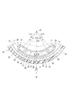
ここで、本実施形態と比較形態との比較により、本実施形態の有利な点を明らかにする。図17に示すように、比較形態による位置検出装置200は、第1ヨーク201および第2ヨーク202を対向方向に見たときの幅が、回転方向の両端部203、204の幅w2から中央の幅w1にかけて漸次的に小さくなっている。
Here, the advantages of the present embodiment will be clarified by comparing the present embodiment with the comparative embodiment. As shown in FIG. 17, in the
本実施形態と比較形態とで体格を同等とするため幅b2=幅w2とし、また、各ヨークの中央部の幅b1および幅w1を外乱耐性が確保可能な所定の幅に設計する(幅b1=幅w1)場合、図4に示すように、本実施形態(実線の特性線L1)は、比較形態(破線の特性線L0)と比べて、各ヨーク間の漏洩磁束が増える。 In order to make the physique the same in this embodiment and the comparative embodiment, the width b2 = width w2 is set, and the width b1 and the width w1 of the central portion of each yoke are designed to be a predetermined width that can secure disturbance resistance (width b1 = Width w1) In the case of this embodiment (solid characteristic line L1), as shown in FIG. 4, the leakage magnetic flux between the yokes increases compared to the comparative form (dashed characteristic line L0).
(効果)
以上説明したように、第1実施形態では、第1ヨーク10の中間部35および第2ヨーク15の中間部36の幅b1は、両端部11、12、16、17の幅b2よりも小さく且つ回転方向で一定である。
このように構成することで、前述の比較形態と比べて、各ヨーク間の漏洩磁束が増える。各ヨーク間の漏洩磁束が増えることによって、(1)ホール素子33が検出する磁束密度に対して外乱磁場が影響する割合が小さくなるので、外乱磁場に対する耐性が向上し、また、(2)ホール素子33による磁電変換における信号増幅を小さく設定することができるので、電源ノイズ等の増幅影響が小さくなり、ホール素子33の出力電圧が理想に対して変動しにくい。
(effect)
As described above, in the first embodiment, the width b1 of the
By comprising in this way, the leakage magnetic flux between each yoke increases compared with the above-mentioned comparative form. By increasing the leakage magnetic flux between the yokes, (1) the influence of the disturbance magnetic field on the magnetic flux density detected by the
したがって、第1実施形態によれば、第1ヨーク10および第2ヨーク15の回転方向の中央部の外乱耐性の低下を抑制しつつ、ホール素子33の出力電圧Vの直線性(特性線L2の直線性)を向上させることができる。
また、第1ヨーク10および第2ヨーク15は、前述の比較形態と比べて形状が単純なものとなり、設計および製造が容易となる。
Therefore, according to the first embodiment, the linearity of the output voltage V of the Hall element 33 (characteristic line L2 of the characteristic line L2) is suppressed while suppressing a decrease in disturbance resistance at the central portion in the rotational direction of the
Further, the
また、第1実施形態では、中間範囲θbは、検出範囲θfsよりも大きく且つ検出範囲θfsを全て含むように設定されている。そのため、中間範囲θbのうち、特性線L2の傾きが比較的大きく変化する両端部分を除く範囲を検出範囲θfsとすることができる。したがって、検出範囲θfsにおける特性線L2の直線性を向上させることができる。 In the first embodiment, the intermediate range θb is set to be larger than the detection range θfs and include all the detection ranges θfs. Therefore, a range excluding both end portions where the slope of the characteristic line L2 changes relatively large in the intermediate range θb can be set as the detection range θfs. Therefore, the linearity of the characteristic line L2 in the detection range θfs can be improved.
また、第1実施形態では、中間範囲θbは、検出範囲θfsにおける特性線L2と理想直線L3との出力信号差が所定値V1以内となるように設定されている。したがって、検出範囲θfsにおいて特性線L2を理想直線L3に近づけて、特性線L2の直線性を一層向上させることができる。 In the first embodiment, the intermediate range θb is set such that the output signal difference between the characteristic line L2 and the ideal straight line L3 in the detection range θfs is within a predetermined value V1. Therefore, the characteristic line L2 can be brought closer to the ideal straight line L3 in the detection range θfs, and the linearity of the characteristic line L2 can be further improved.
<第2実施形態>
本発明の第2実施形態による位置検出装置について図6、図7を参照して説明する。
図6、図7に示すように、位置検出装置40の第1ヨーク41は、一端部11と他端部12との間に中間部42を有している。第1ヨーク41の中間部42と第2ヨーク15の中間部36とは、対向方向に見たときの幅が異なる。
Second Embodiment
A position detection apparatus according to a second embodiment of the present invention will be described with reference to FIGS.
As shown in FIGS. 6 and 7, the
具体的には、図7に示すように、第1ヨーク41の中間部42の幅b3は、第2ヨーク15の中間部36の幅b1よりも大きく、且つ、端部11、12の幅b2よりも小さい。幅b1および幅b3は、第1ヨーク41および第2ヨーク15のパーミアンスが同じになるように設定されている。
第2実施形態によれば、第1ヨーク41と第2ヨーク15との隙間の磁界変化を対向方向で均一にすることができ、検出精度が向上する。また、第2実施形態によれば、第1実施形態と比べて、径方向外側の外乱磁場に対する耐性を向上させることができる。
Specifically, as shown in FIG. 7, the width b3 of the
According to the second embodiment, the magnetic field change in the gap between the
<第3実施形態>
本発明の第3実施形態による位置検出装置について図8、図9を参照して説明する。
図8、図9に示すように、位置検出装置45の第2ヨーク46は、一端部16と他端部17との間に中間部47を有している。第1ヨーク10の中間部35と第2ヨーク46の中間部47とは、対向方向に見たときの幅が異なる。
<Third Embodiment>
A position detection apparatus according to a third embodiment of the present invention will be described with reference to FIGS.
As shown in FIGS. 8 and 9, the
具体的には、図9に示すように、第2ヨーク46の中間部47の幅b4は、第1ヨーク10の中間部35の幅b1よりも大きく、且つ、端部16、17の幅b2よりも小さい。
第3実施形態によれば、第1実施形態と比べて、径方向内側の外乱磁場に対する耐性を向上させることができる。
Specifically, as shown in FIG. 9, the width b4 of the
According to the third embodiment, it is possible to improve resistance to a disturbance magnetic field on the radially inner side as compared with the first embodiment.
<第4実施形態>
本発明の第4実施形態による位置検出装置について図10を参照して説明する。
図10に示すように、位置検出装置50の第1ヨーク51は、一端部52と他端部53との間に中間部54を有している。第1ヨーク51の中間部54と第2ヨーク15の中間部36とは、回転方向に占める範囲が異なる。
<Fourth embodiment>
A position detection apparatus according to a fourth embodiment of the present invention will be described with reference to FIG.
As shown in FIG. 10, the
具体的には、回転方向において第1ヨーク51の中間部54が占める範囲を第1中間範囲θb−1とし、第2ヨーク15の中間部36が占める範囲を第2中間範囲θb−2とすると、第1中間範囲θb−1は、第2中間範囲θb−2よりも小さい。第1中間範囲θb−1および第2中間範囲θb−2は、第1ヨーク51および第2ヨーク15のパーミアンスが同じになるように設定されている。
第4実施形態によれば、第1ヨーク51と第2ヨーク15との隙間の磁界変化を対向方向で均一にすることができ、検出精度が向上する。
Specifically, a range occupied by the
According to the fourth embodiment, the magnetic field change in the gap between the
<第5実施形態>
本発明の第5実施形態による位置検出装置について図11を参照して説明する。
図11に示すように、位置検出装置55の第2ヨーク56は、一端部57と他端部58との間に中間部59を有している。第1ヨーク10の中間部35と第2ヨーク56の中間部59とは、回転方向に占める範囲が異なる。
<Fifth Embodiment>
A position detection apparatus according to a fifth embodiment of the present invention will be described with reference to FIG.
As shown in FIG. 11, the
具体的には、回転方向において第1ヨーク10の中間部35が占める範囲を第1中間範囲θb−3とし、第2ヨーク56の中間部59が占める範囲を第2中間範囲θb−4とすると、第2中間範囲θb−4は、第1中間範囲θb−3よりも小さい。
第4実施形態によれば、第1ヨーク10と第2ヨーク56との隙間の磁界を第1実施形態と異なるものとすることができ、設計自由度が増す。
Specifically, a range occupied by the
According to the fourth embodiment, the magnetic field in the gap between the
<第6実施形態>
本発明の第6実施形態による位置検出装置について図12を参照して説明する。
図12に示すように、位置検出装置60の短絡磁路部61は、漏洩磁界をより集中してホールIC31へ流すための一対の集磁ヨーク62を有している。一対の集磁ヨーク62は、隙間20においてホールIC31を挟んで対向方向へ並ぶように設けられている。
第6実施形態によれば、ダイナミックレンジ(検出範囲θfsにおける出力電圧Vの幅)を大きくすることによって、検出精度を向上させることができる。
<Sixth Embodiment>
A position detection apparatus according to a sixth embodiment of the present invention will be described with reference to FIG.
As shown in FIG. 12, the short-circuit
According to the sixth embodiment, the detection accuracy can be improved by increasing the dynamic range (the width of the output voltage V in the detection range θfs).
<第7実施形態>
本発明の第7実施形態による位置検出装置について図13、図14を参照して説明する。
位置検出装置70では、第1ヨーク71および第2ヨーク72は、回転体73の軸方向で互いに対向するように、且つ回転体73の回転方向へ延びるように形成されている。これにより、各ヨーク71、72および各磁石25、26は、径方向外側に開口する閉磁気回路を形成している。短絡磁路部30は、回転体73に対し径方向外側から閉磁気回路内に挿入されている。
このような形態であっても、第1ヨーク71の中間部74および第2ヨーク72の中間部75の幅b1が両端部76〜79の幅b2よりも小さく且つ回転方向で一定であれば、第1実施形態と同様の効果を得ることができる。
<Seventh embodiment>
A position detection apparatus according to a seventh embodiment of the present invention will be described with reference to FIGS.
In the
Even in such a form, if the width b1 of the
<第8実施形態>
本発明の第8実施形態による位置検出装置について図15、図16を参照して説明する。なお、図16では、便宜上、出力部材102を図示していない。
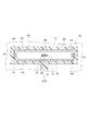
位置検出装置100は、シフトアクチュエータ101に適用されている。シフトアクチュエータ101は、例えば自動制御式マニュアルトランスミッションまたはデュアルクラッチトランスミッション等から構成された変速機に設けられ、シフト操作およびセレクト操作を行うアクチュエータである。シフトアクチュエータ101の出力部材102は、ハウジング111に対し直線移動する。出力部材102は特許請求の範囲に記載の「検出対象」に相当し、ハウジング111は特許請求の範囲に記載の「基準部材」に相当する。
<Eighth Embodiment>
A position detection apparatus according to an eighth embodiment of the present invention will be described with reference to FIGS. In FIG. 16, the
The
位置検出装置100では、第1ヨーク103、第2ヨーク104、第1磁石25および第2磁石26により閉磁気回路が形成されている。第1ヨーク103および第2ヨーク104は、出力部材102の移動方向に沿うように直線状に形成されており、出力部材102に固定されている。
このように、基準部材に対し直線移動する移動体の位置を検出する形態であっても、第1ヨーク103の中間部105および第2ヨーク104の中間部106の幅b1が両端部107〜110の幅b2よりも小さく且つ移動方向で一定であれば、第1実施形態と同様の効果を得ることができる。
In the
As described above, even if the position of the moving body that moves linearly with respect to the reference member is detected, the width b1 of the
<他の実施形態>
本発明の他の実施形態では、第1ヨークの一端部および他端部は、幅が異なっていてもよい。また、第2ヨークの一端部および他端部は、幅が異なっていてもよい。
本発明の他の実施形態では、閉磁気回路を構成する部材がケースに設けられ、ホールICが回転体に設けられてもよい。
本発明の他の実施形態では、第1磁石および第2磁石に代えて、例えば電磁石などの他の磁束発生手段が設けられてもよい。
<Other embodiments>
In another embodiment of the present invention, the first yoke and the other end may have different widths. Moreover, the width | variety may differ in the one end part and other end part of a 2nd yoke.
In another embodiment of the present invention, the member constituting the closed magnetic circuit may be provided in the case, and the Hall IC may be provided in the rotating body.
In another embodiment of the present invention, other magnetic flux generating means such as an electromagnet may be provided instead of the first magnet and the second magnet.
本発明の他の実施形態では、位置検出装置は、例えばモータと出力軸との間に設けられる減速機の最終減速部材などの他の回転部材に設けられてもよい。
本発明の他の実施形態では、回転駆動装置は、ウェイストゲートバルブ装置に限らず、例えば可変容量ターボの可変ベーン制御装置、排気スロットルまたは排気切替弁のバルブ作動装置、あるいは、可変吸気機構のバルブ作動装置などの他の装置に適用されてもよい。
本発明は、上述した実施形態に限定されるものではなく、発明の趣旨を逸脱しない範囲で種々の形態で実施可能である。
In another embodiment of the present invention, the position detection device may be provided on another rotating member such as a final reduction member of a reduction gear provided between the motor and the output shaft.
In another embodiment of the present invention, the rotary drive device is not limited to the waste gate valve device, but is, for example, a variable vane control device for a variable displacement turbo, a valve operating device for an exhaust throttle or an exhaust switching valve, or a valve for a variable intake mechanism. It may be applied to other devices such as actuating devices.
The present invention is not limited to the embodiments described above, and can be implemented in various forms without departing from the spirit of the invention.
5、40、45、50、55、60、70、100・・・位置検出装置
10、41、51、71、103・・・第1ヨーク(第1磁束伝達部材)
11、16、52、57、76、78、107、109・・・一端部
12、17、53、58、77、79、108、110・・・他端部
15、46、56、72、104・・・第2ヨーク(第2磁束伝達部材)
25・・・第1磁石(第1磁束発生手段)
26・・・第2磁石(第2磁束発生手段)
33・・・ホール素子(磁束密度検出手段)
35、42、54、74、105・・・第1中間部
36、47、59、75、106・・・第2中間部
81・・・ハウジング(基準部材)
87・・・回転体(検出対象)
5, 40, 45, 50, 55, 60, 70, 100 ...
11, 16, 52, 57, 76, 78, 107, 109 ... one
25 ... 1st magnet (1st magnetic flux generation means)
26: Second magnet (second magnetic flux generating means)
33 ... Hall element (magnetic flux density detection means)
35, 42, 54, 74, 105 ... 1st
87 ... Rotating body (detection target)
Claims (8)
前記検出対象の移動方向へ沿うように延びている第1磁束伝達部材(10、41、51、71、103)と、
前記第1磁束伝達部材と並行して前記移動方向へ沿うように延び、前記第1磁束伝達部材と共に前記基準部材および前記検出対象の一方に設けられる第2磁束伝達部材(15、46、56、72、104)と、
前記第1磁束伝達部材および前記第2磁束伝達部材のうち前記移動方向の一端部(11、16、52、57、76、78、107、109)同士の間に設けられている第1磁束発生手段(25)と、
前記第1磁束伝達部材および前記第2磁束伝達部材のうち前記移動方向の他端部(12、17、53、58、77、79、108、110)同士の間に設けられている第2磁束発生手段(26)と、
前記第1磁束伝達部材と前記第2磁束伝達部材との間の隙間(20)に位置し、前記基準部材および前記検出対象の他方に設けられ、通過する磁束の密度に応じた信号を出力する磁束密度検出手段(33)と、
を備え、
前記第1磁束伝達部材と前記第2磁束伝達部材とが対向する方向を対向方向とすると、
前記第1磁束伝達部材は、当該第1磁束伝達部材の前記一端部と前記他端部との間に、前記対向方向に見たときの幅が前記一端部および前記他端部よりも小さく且つ前記移動方向で一定である第1中間部(35、42、54、74、105)を有し、
前記第2磁束伝達部材は、当該第2磁束伝達部材の前記一端部と前記他端部との間に、前記対向方向に見たときの幅が前記一端部および前記他端部よりも小さく且つ前記移動方向で一定である第2中間部(36、47、59、75、106)を有していることを特徴とする位置検出装置。 A position detection device (5, 40, 45, 50, 55, 60, 70, 100) capable of detecting the position of a detection target (87, 102) that moves relative to a reference member (82),
A first magnetic flux transmission member (10, 41, 51, 71, 103) extending along the moving direction of the detection target;
The second magnetic flux transmission member (15, 46, 56, which extends along the moving direction in parallel with the first magnetic flux transmission member and is provided on one of the reference member and the detection target together with the first magnetic flux transmission member. 72, 104)
A first magnetic flux generation provided between one end portions (11, 16, 52, 57, 76, 78, 107, 109) in the moving direction of the first magnetic flux transmission member and the second magnetic flux transmission member. Means (25);
The second magnetic flux provided between the other end portions (12, 17, 53, 58, 77, 79, 108, 110) in the moving direction of the first magnetic flux transmission member and the second magnetic flux transmission member. Generating means (26);
It is located in the gap (20) between the first magnetic flux transmission member and the second magnetic flux transmission member, is provided on the other of the reference member and the detection target, and outputs a signal corresponding to the density of the magnetic flux passing therethrough. Magnetic flux density detection means (33);
With
When the direction in which the first magnetic flux transmission member and the second magnetic flux transmission member are opposed is an opposing direction,
The first magnetic flux transmission member has a width smaller than the one end and the other end between the one end and the other end of the first magnetic flux transmission member when viewed in the facing direction. A first intermediate portion (35, 42, 54, 74, 105) that is constant in the direction of movement;
The second magnetic flux transmission member has a width smaller than the one end and the other end between the one end and the other end of the second magnetic flux transmission member when viewed in the facing direction. A position detecting device comprising a second intermediate portion (36, 47, 59, 75, 106) that is constant in the moving direction.
前記第1中間範囲および前記第2中間範囲は、前記検出範囲よりも大きく且つ前記検出範囲を全て含むように設定されていることを特徴とする請求項1に記載の位置検出装置。 A range in which the position of the detection target is detected in the moving direction is a detection range (θfs), and a range occupied by the first intermediate portion of the first magnetic flux transmission member in the moving direction is a first intermediate range (θb, θb− 1 and θb-3), and the range occupied by the second intermediate portion of the second magnetic flux transmission member in the moving direction is a second intermediate range (θb, θb-2, θb-4),
The position detection apparatus according to claim 1, wherein the first intermediate range and the second intermediate range are set to be larger than the detection range and include all of the detection ranges.
前記第1中間範囲および第2中間範囲は、前記検出範囲における前記特性線と前記理想直線との出力信号差が所定値(V1)以内となるように設定されていることを特徴とする請求項2に記載の位置検出装置。 The position of the detection target where the density (B) of the magnetic flux passing through the magnetic flux density detection means is 0 is set to 0 position, and the position of the detection target and the output signal (V) of the magnetic flux density detection means in an orthogonal coordinate system The graph line indicating the relationship is defined as the characteristic line (L2), the coordinate on the characteristic line corresponding to the 0 position is defined as 0 point (P0 L2 ), and the graph line passing through the 0 point and having an ideal inclination is ideal. Assuming a straight line (L3)
The first intermediate range and the second intermediate range are set such that an output signal difference between the characteristic line and the ideal straight line in the detection range is within a predetermined value (V1). 2. The position detection device according to 2.
前記第1中間範囲は、前記第2中間範囲とは異なることを特徴とする請求項1〜3のいずれか一項に記載の位置検出装置(50、55)。 A range occupied by the first intermediate portion (35, 54) of the first magnetic flux transmission member (10, 51) in the movement direction is a first intermediate range (θb-1, θb-3), and the range in the movement direction is When the range occupied by the second intermediate portion (36, 59) of the second magnetic flux transmission member (15, 56) is the second intermediate range (θb-2, θb-4),
The position detection device (50, 55) according to any one of claims 1 to 3, wherein the first intermediate range is different from the second intermediate range.
前記第1磁束伝達部(10、41、51)および前記第2磁束伝達部(15、46、56)は、前記移動方向へ沿うように弧状に形成され、且つ前記検出対象の径方向において互いに対向していることを特徴とする請求項1〜5のいずれか一項に記載の位置検出装置(5、40、45、50、55、60)。 The detection object (87) rotates relative to the reference member,
The first magnetic flux transmission part (10, 41, 51) and the second magnetic flux transmission part (15, 46, 56) are formed in an arc shape along the moving direction, and are mutually in the radial direction of the detection target. The position detection device (5, 40, 45, 50, 55, 60) according to any one of claims 1 to 5, wherein the position detection device faces each other.
前記第1磁束伝達部(71)および前記第2磁束伝達部(72)は、前記移動方向へ沿うように弧状に形成され、且つ前記検出対象の軸方向において互いに対向していることを特徴とする請求項1〜5のいずれか一項に記載の位置検出装置(70)。 The detection object (87) rotates relative to the reference member,
The first magnetic flux transmission part (71) and the second magnetic flux transmission part (72) are formed in an arc shape along the moving direction, and are opposed to each other in the axial direction of the detection target. The position detection device (70) according to any one of claims 1 to 5.
前記第1磁束伝達部(103)および前記第2磁束伝達部(104)は、前記移動方向へ沿うように直線状に形成されていることを特徴とする請求項1〜5のいずれか一項に記載の位置検出装置(100)。 The detection object (102) moves linearly with respect to the reference member,
The said 1st magnetic flux transmission part (103) and the said 2nd magnetic flux transmission part (104) are linearly formed so that the said moving direction may be followed, The any one of Claims 1-5 characterized by the above-mentioned. The position detection apparatus (100) as described in.
Priority Applications (5)
| Application Number | Priority Date | Filing Date | Title |
|---|---|---|---|
| JP2014207126A JP5904252B2 (en) | 2013-12-27 | 2014-10-08 | Position detection device |
| US14/576,568 US9739638B2 (en) | 2013-12-27 | 2014-12-19 | Position sensing apparatus |
| DE102014226991.1A DE102014226991A1 (en) | 2013-12-27 | 2014-12-24 | Position sensing device |
| CN201410829418.3A CN104748654B (en) | 2013-12-27 | 2014-12-26 | position sensing device |
| US15/650,025 US10139248B2 (en) | 2013-12-27 | 2017-07-14 | Position sensing apparatus |
Applications Claiming Priority (3)
| Application Number | Priority Date | Filing Date | Title |
|---|---|---|---|
| JP2013271729 | 2013-12-27 | ||
| JP2013271729 | 2013-12-27 | ||
| JP2014207126A JP5904252B2 (en) | 2013-12-27 | 2014-10-08 | Position detection device |
Publications (2)
| Publication Number | Publication Date |
|---|---|
| JP2015143675A JP2015143675A (en) | 2015-08-06 |
| JP5904252B2 true JP5904252B2 (en) | 2016-04-13 |
Family
ID=53372330
Family Applications (1)
| Application Number | Title | Priority Date | Filing Date |
|---|---|---|---|
| JP2014207126A Active JP5904252B2 (en) | 2013-12-27 | 2014-10-08 | Position detection device |
Country Status (4)
| Country | Link |
|---|---|
| US (2) | US9739638B2 (en) |
| JP (1) | JP5904252B2 (en) |
| CN (1) | CN104748654B (en) |
| DE (1) | DE102014226991A1 (en) |
Families Citing this family (6)
| Publication number | Priority date | Publication date | Assignee | Title |
|---|---|---|---|---|
| US9791296B2 (en) * | 2015-05-05 | 2017-10-17 | Metropolitan Industries, Inc. | System and method of synchronously switching electrical phases of a permanent magnet synchronous motor |
| JP6651962B2 (en) * | 2016-04-12 | 2020-02-19 | 株式会社デンソー | Position detection device |
| DE102017222674A1 (en) * | 2016-12-29 | 2018-07-05 | Robert Bosch Gmbh | displacement sensor |
| JP6766849B2 (en) * | 2018-01-16 | 2020-10-14 | 株式会社デンソー | Rotation angle detector |
| PT3839255T (en) * | 2019-12-19 | 2022-06-06 | Contelec Ag | Magnetic sensor and axial piston pump |
| US11846529B2 (en) | 2021-04-19 | 2023-12-19 | Joral Llc | Magnetic rack and pinion linear magnetic encoder and position sensing system |
Family Cites Families (23)
| Publication number | Priority date | Publication date | Assignee | Title |
|---|---|---|---|---|
| KR900004780B1 (en) * | 1985-09-13 | 1990-07-05 | 후지쓰 가부시끼가이샤 | Phase detective apparatus using mangetic sensor |
| US5757179A (en) * | 1994-03-04 | 1998-05-26 | Cts Corporation | Position sensor with improved magnetic circuit |
| JP3235400B2 (en) | 1995-04-20 | 2001-12-04 | 日産自動車株式会社 | Magnetic position sensor |
| US6222359B1 (en) * | 1999-06-18 | 2001-04-24 | Cts Corporation | Non-contacting position sensor using radial bipolar tapered magnets |
| JP2001272205A (en) * | 2000-02-15 | 2001-10-05 | Ab Elektronik Gmbh | Sensor for angle of rotation |
| US6806701B2 (en) * | 2000-02-15 | 2004-10-19 | Ab Elektronik Gmbh | Rotation angle sensor |
| US6498480B1 (en) * | 2000-11-22 | 2002-12-24 | Wabash Technologies, Inc. | Magnetic non-contacting rotary transducer |
| US6753680B2 (en) * | 2000-11-29 | 2004-06-22 | Ronald J. Wolf | Position sensor |
| US6731109B2 (en) * | 2002-07-12 | 2004-05-04 | Wabash Technologies, Inc. | Magnetic position sensor having a stepped magnet interface |
| US6998838B2 (en) * | 2003-02-25 | 2006-02-14 | Delphi Technologies, Inc. | Linear position sensor having enhanced sensing range to magnet size ratio |
| US6992478B2 (en) * | 2003-12-22 | 2006-01-31 | Cts Corporation | Combination hall effect position sensor and switch |
| US7242183B2 (en) * | 2005-02-28 | 2007-07-10 | Delphi Technologies, Inc. | Low cost linear position sensor employing one permanent magnat and one galvanomagnetic sensing element |
| US7391208B2 (en) * | 2005-03-21 | 2008-06-24 | Wolf Ronald J | Rotary position sensor |
| US7151369B1 (en) * | 2005-09-12 | 2006-12-19 | Wolf Ronald J | Position sensor |
| JP5121201B2 (en) * | 2006-09-28 | 2013-01-16 | オリンパスメディカルシステムズ株式会社 | Detector position detection system |
| US7463023B1 (en) * | 2007-08-02 | 2008-12-09 | Delphi Technologies, Inc. | Non-contacting rotary and linear travel sensor |
| JP2009085913A (en) * | 2007-10-03 | 2009-04-23 | Nippon Seiki Co Ltd | Position detector |
| DE102008021327B4 (en) * | 2008-04-29 | 2010-04-15 | Zf Friedrichshafen Ag | Inductive sensor for speed, direction of rotation and position measurements in the high temperature range |
| US20090295377A1 (en) * | 2008-06-03 | 2009-12-03 | Moreno Daniel J | Contactless position sensor for vehicle |
| DE102009035091A1 (en) * | 2009-07-28 | 2011-02-10 | Mahle International Gmbh | Position sensor and linear actuator |
| JP5818104B2 (en) * | 2012-10-12 | 2015-11-18 | 株式会社デンソー | Rotation angle detector |
| JP5725007B2 (en) * | 2012-12-27 | 2015-05-27 | 株式会社デンソー | Position detection device |
| JP5786848B2 (en) * | 2012-12-27 | 2015-09-30 | 株式会社デンソー | Position detection device |
-
2014
- 2014-10-08 JP JP2014207126A patent/JP5904252B2/en active Active
- 2014-12-19 US US14/576,568 patent/US9739638B2/en active Active
- 2014-12-24 DE DE102014226991.1A patent/DE102014226991A1/en not_active Ceased
- 2014-12-26 CN CN201410829418.3A patent/CN104748654B/en active Active
-
2017
- 2017-07-14 US US15/650,025 patent/US10139248B2/en active Active
Also Published As
| Publication number | Publication date |
|---|---|
| JP2015143675A (en) | 2015-08-06 |
| US10139248B2 (en) | 2018-11-27 |
| DE102014226991A1 (en) | 2015-07-02 |
| US20170314964A1 (en) | 2017-11-02 |
| US20150185047A1 (en) | 2015-07-02 |
| CN104748654A (en) | 2015-07-01 |
| US9739638B2 (en) | 2017-08-22 |
| CN104748654B (en) | 2019-01-04 |
Similar Documents
| Publication | Publication Date | Title |
|---|---|---|
| JP5725007B2 (en) | Position detection device | |
| JP5904252B2 (en) | Position detection device | |
| JP6079618B2 (en) | Rotation drive | |
| US10082405B2 (en) | Position detector with a minimum magnetic flux density position shifted from a center of a gap | |
| US7671584B2 (en) | Rotation angle detection device | |
| US20070108968A1 (en) | Rotation angle detection device | |
| JP5786848B2 (en) | Position detection device | |
| JP3539299B2 (en) | Rotation angle detector | |
| JP5720961B2 (en) | Position detection device | |
| US10060760B2 (en) | Magnetix flux position detector that detects the magnetic flux at minimum position along a magnetic circuit | |
| JP2014126553A (en) | Position detector | |
| JP5683703B2 (en) | Position detection device | |
| US20130320967A1 (en) | Rotation angle detection device | |
| JP2014126550A (en) | Position detector | |
| JP3666669B2 (en) | Temperature sensitive actuator | |
| JP5035697B2 (en) | Rotation angle detector | |
| JP6233278B2 (en) | Rotation position detector |
Legal Events
| Date | Code | Title | Description |
|---|---|---|---|
| A621 | Written request for application examination |
Free format text: JAPANESE INTERMEDIATE CODE: A621 Effective date: 20150924 |
|
| TRDD | Decision of grant or rejection written | ||
| A01 | Written decision to grant a patent or to grant a registration (utility model) |
Free format text: JAPANESE INTERMEDIATE CODE: A01 Effective date: 20160216 |
|
| A61 | First payment of annual fees (during grant procedure) |
Free format text: JAPANESE INTERMEDIATE CODE: A61 Effective date: 20160229 |
|
| R151 | Written notification of patent or utility model registration |
Ref document number: 5904252 Country of ref document: JP Free format text: JAPANESE INTERMEDIATE CODE: R151 |
|
| R250 | Receipt of annual fees |
Free format text: JAPANESE INTERMEDIATE CODE: R250 |
|
| R250 | Receipt of annual fees |
Free format text: JAPANESE INTERMEDIATE CODE: R250 |
|
| R250 | Receipt of annual fees |
Free format text: JAPANESE INTERMEDIATE CODE: R250 |
|
| R250 | Receipt of annual fees |
Free format text: JAPANESE INTERMEDIATE CODE: R250 |
|
| R250 | Receipt of annual fees |
Free format text: JAPANESE INTERMEDIATE CODE: R250 |