JP5902090B2 - Box structure joint construction method - Google Patents
Box structure joint construction method Download PDFInfo
- Publication number
- JP5902090B2 JP5902090B2 JP2012529409A JP2012529409A JP5902090B2 JP 5902090 B2 JP5902090 B2 JP 5902090B2 JP 2012529409 A JP2012529409 A JP 2012529409A JP 2012529409 A JP2012529409 A JP 2012529409A JP 5902090 B2 JP5902090 B2 JP 5902090B2
- Authority
- JP
- Japan
- Prior art keywords
- plate
- plates
- box structure
- wall
- construction method
- Prior art date
- Legal status (The legal status is an assumption and is not a legal conclusion. Google has not performed a legal analysis and makes no representation as to the accuracy of the status listed.)
- Expired - Fee Related
Links
- 238000010276 construction Methods 0.000 title claims description 16
- 239000010410 layer Substances 0.000 claims description 10
- 238000000034 method Methods 0.000 claims description 10
- 239000002356 single layer Substances 0.000 claims description 7
- 238000005304 joining Methods 0.000 claims description 5
- 239000000463 material Substances 0.000 claims description 5
- 239000002023 wood Substances 0.000 claims description 4
- 239000011521 glass Substances 0.000 claims description 3
- 239000002184 metal Substances 0.000 claims description 2
- 229920003023 plastic Polymers 0.000 claims description 2
- 239000004033 plastic Substances 0.000 claims description 2
- 239000004575 stone Substances 0.000 claims description 2
- 239000011120 plywood Substances 0.000 claims 1
- 238000005516 engineering process Methods 0.000 description 4
- 238000004519 manufacturing process Methods 0.000 description 2
- 238000000465 moulding Methods 0.000 description 2
- VVQNEPGJFQJSBK-UHFFFAOYSA-N Methyl methacrylate Chemical compound COC(=O)C(C)=C VVQNEPGJFQJSBK-UHFFFAOYSA-N 0.000 description 1
- 229920005372 Plexiglas® Polymers 0.000 description 1
- 229920000122 acrylonitrile butadiene styrene Polymers 0.000 description 1
- 239000000853 adhesive Substances 0.000 description 1
- 230000001070 adhesive effect Effects 0.000 description 1
- 239000002131 composite material Substances 0.000 description 1
- 239000004567 concrete Substances 0.000 description 1
- 230000008878 coupling Effects 0.000 description 1
- 238000010168 coupling process Methods 0.000 description 1
- 238000005859 coupling reaction Methods 0.000 description 1
- 238000005520 cutting process Methods 0.000 description 1
- 238000010586 diagram Methods 0.000 description 1
- 238000003780 insertion Methods 0.000 description 1
- 230000037431 insertion Effects 0.000 description 1
- 230000001788 irregular Effects 0.000 description 1
- 238000003754 machining Methods 0.000 description 1
- 239000000155 melt Substances 0.000 description 1
- 238000003860 storage Methods 0.000 description 1
- 238000003466 welding Methods 0.000 description 1
Images


Classifications
-
- B—PERFORMING OPERATIONS; TRANSPORTING
- B65—CONVEYING; PACKING; STORING; HANDLING THIN OR FILAMENTARY MATERIAL
- B65D—CONTAINERS FOR STORAGE OR TRANSPORT OF ARTICLES OR MATERIALS, e.g. BAGS, BARRELS, BOTTLES, BOXES, CANS, CARTONS, CRATES, DRUMS, JARS, TANKS, HOPPERS, FORWARDING CONTAINERS; ACCESSORIES, CLOSURES, OR FITTINGS THEREFOR; PACKAGING ELEMENTS; PACKAGES
- B65D7/00—Containers having bodies formed by interconnecting or uniting two or more rigid, or substantially rigid, components made wholly or mainly of metal
- B65D7/12—Containers having bodies formed by interconnecting or uniting two or more rigid, or substantially rigid, components made wholly or mainly of metal characterised by wall construction or by connections between walls
- B65D7/24—Containers having bodies formed by interconnecting or uniting two or more rigid, or substantially rigid, components made wholly or mainly of metal characterised by wall construction or by connections between walls collapsible, e.g. with all parts detachable
-
- B—PERFORMING OPERATIONS; TRANSPORTING
- B65—CONVEYING; PACKING; STORING; HANDLING THIN OR FILAMENTARY MATERIAL
- B65D—CONTAINERS FOR STORAGE OR TRANSPORT OF ARTICLES OR MATERIALS, e.g. BAGS, BARRELS, BOTTLES, BOXES, CANS, CARTONS, CRATES, DRUMS, JARS, TANKS, HOPPERS, FORWARDING CONTAINERS; ACCESSORIES, CLOSURES, OR FITTINGS THEREFOR; PACKAGING ELEMENTS; PACKAGES
- B65D11/00—Containers having bodies formed by interconnecting or uniting two or more rigid, or substantially rigid, components made wholly or mainly of plastics material
- B65D11/18—Containers having bodies formed by interconnecting or uniting two or more rigid, or substantially rigid, components made wholly or mainly of plastics material collapsible, i.e. with walls hinged together or detachably connected
- B65D11/1866—Containers having bodies formed by interconnecting or uniting two or more rigid, or substantially rigid, components made wholly or mainly of plastics material collapsible, i.e. with walls hinged together or detachably connected with detachable components
- B65D11/1873—Containers having bodies formed by interconnecting or uniting two or more rigid, or substantially rigid, components made wholly or mainly of plastics material collapsible, i.e. with walls hinged together or detachably connected with detachable components all walls are detached from each other to collapse the container
-
- B—PERFORMING OPERATIONS; TRANSPORTING
- B65—CONVEYING; PACKING; STORING; HANDLING THIN OR FILAMENTARY MATERIAL
- B65D—CONTAINERS FOR STORAGE OR TRANSPORT OF ARTICLES OR MATERIALS, e.g. BAGS, BARRELS, BOTTLES, BOXES, CANS, CARTONS, CRATES, DRUMS, JARS, TANKS, HOPPERS, FORWARDING CONTAINERS; ACCESSORIES, CLOSURES, OR FITTINGS THEREFOR; PACKAGING ELEMENTS; PACKAGES
- B65D13/00—Containers having bodies formed by interconnecting two or more rigid, or substantially rigid, components made wholly or mainly of the same material, other than metal, plastics, wood or substitutes therefor
- B65D13/02—Containers having bodies formed by interconnecting two or more rigid, or substantially rigid, components made wholly or mainly of the same material, other than metal, plastics, wood or substitutes therefor of glass, pottery, or other ceramic material
-
- B—PERFORMING OPERATIONS; TRANSPORTING
- B65—CONVEYING; PACKING; STORING; HANDLING THIN OR FILAMENTARY MATERIAL
- B65D—CONTAINERS FOR STORAGE OR TRANSPORT OF ARTICLES OR MATERIALS, e.g. BAGS, BARRELS, BOTTLES, BOXES, CANS, CARTONS, CRATES, DRUMS, JARS, TANKS, HOPPERS, FORWARDING CONTAINERS; ACCESSORIES, CLOSURES, OR FITTINGS THEREFOR; PACKAGING ELEMENTS; PACKAGES
- B65D88/00—Large containers
- B65D88/52—Large containers collapsible, i.e. with walls hinged together or detachably connected
- B65D88/526—Large containers collapsible, i.e. with walls hinged together or detachably connected with detachable side walls
- B65D88/528—Large containers collapsible, i.e. with walls hinged together or detachably connected with detachable side walls all side walls detached from each other to collapse the container
-
- B—PERFORMING OPERATIONS; TRANSPORTING
- B65—CONVEYING; PACKING; STORING; HANDLING THIN OR FILAMENTARY MATERIAL
- B65D—CONTAINERS FOR STORAGE OR TRANSPORT OF ARTICLES OR MATERIALS, e.g. BAGS, BARRELS, BOTTLES, BOXES, CANS, CARTONS, CRATES, DRUMS, JARS, TANKS, HOPPERS, FORWARDING CONTAINERS; ACCESSORIES, CLOSURES, OR FITTINGS THEREFOR; PACKAGING ELEMENTS; PACKAGES
- B65D9/00—Containers having bodies formed by interconnecting or uniting two or more rigid, or substantially rigid, components made wholly or mainly of wood or substitutes therefor
- B65D9/12—Containers having bodies formed by interconnecting or uniting two or more rigid, or substantially rigid, components made wholly or mainly of wood or substitutes therefor collapsible, e.g. with all parts detachable
-
- B—PERFORMING OPERATIONS; TRANSPORTING
- B65—CONVEYING; PACKING; STORING; HANDLING THIN OR FILAMENTARY MATERIAL
- B65D—CONTAINERS FOR STORAGE OR TRANSPORT OF ARTICLES OR MATERIALS, e.g. BAGS, BARRELS, BOTTLES, BOXES, CANS, CARTONS, CRATES, DRUMS, JARS, TANKS, HOPPERS, FORWARDING CONTAINERS; ACCESSORIES, CLOSURES, OR FITTINGS THEREFOR; PACKAGING ELEMENTS; PACKAGES
- B65D9/00—Containers having bodies formed by interconnecting or uniting two or more rigid, or substantially rigid, components made wholly or mainly of wood or substitutes therefor
- B65D9/32—Details of wooden walls; Connections between walls
-
- Y—GENERAL TAGGING OF NEW TECHNOLOGICAL DEVELOPMENTS; GENERAL TAGGING OF CROSS-SECTIONAL TECHNOLOGIES SPANNING OVER SEVERAL SECTIONS OF THE IPC; TECHNICAL SUBJECTS COVERED BY FORMER USPC CROSS-REFERENCE ART COLLECTIONS [XRACs] AND DIGESTS
- Y10—TECHNICAL SUBJECTS COVERED BY FORMER USPC
- Y10T—TECHNICAL SUBJECTS COVERED BY FORMER US CLASSIFICATION
- Y10T29/00—Metal working
- Y10T29/49—Method of mechanical manufacture
- Y10T29/49826—Assembling or joining
Landscapes
- Engineering & Computer Science (AREA)
- Mechanical Engineering (AREA)
- Life Sciences & Earth Sciences (AREA)
- Wood Science & Technology (AREA)
- Ceramic Engineering (AREA)
- Assembled Shelves (AREA)
- Rigid Containers With Two Or More Constituent Elements (AREA)
- Joining Of Building Structures In Genera (AREA)
- Finishing Walls (AREA)
- Connection Of Plates (AREA)
Description
本発明は、多くの人工物を製造するのに使用される技術およびアセンブリ装置に関し、以下のような数多くの予測不可能な用途に関わるものである。
・本棚、テーブル、椅子などの家具および備品。
・種類、サイズ、質および構成が任意の包装体および箱。
・電子製品、機械などに対する多種類の枠。
・小さな家、容器、複雑な構造、台、小屋、タンクなど。
・玩具および小物。
The present invention relates to the technology and assembly equipment used to manufacture many artifacts and involves a number of unpredictable applications such as:
・ Furniture and equipment such as bookshelves, tables and chairs.
・ Packages and boxes of any type, size, quality and configuration.
・ Various types of frames for electronic products and machines.
・ Small houses, containers, complex structures, stands, huts, tanks, etc.
・ Toys and accessories.
一般な背景は、接着剤、ネジ、ボルト、溶接、係合システム、成形を利用する前記技術からなるものである。本発明は、多くの場面でそのような技術を代替することを約束するものである。 The general background consists of such techniques that utilize adhesives, screws, bolts, welding, engagement systems, and molding. The present invention promises to replace such technology in many situations.
以前に解決されなかった問題に代表される特定の技術水準もあるが、この技術は、箱形構造の5辺の設定を超えたことがなく、完全な係合システムを伴う解決策を見出してはいない。 Although there are certain state of the art represented by problems that have not been solved before, this technique has never exceeded the five-sided setting of a box structure and found a solution with a complete engagement system. No.
特許文献1には、ブラケットおよびネジを利用する見かけ上の解決策が示されているが、これは、産業上の適用可能性という面では複合的で非効率になり、距離機能の面では曖昧になるものである Patent Document 1 discloses an apparent solution that uses brackets and screws, but this is complex and inefficient in terms of industrial applicability and is ambiguous in terms of distance function. Is what
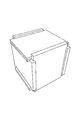
本発明の接合構築システムは、少なくとも7枚のプレートを備える箱構造のための接合構築システムであって、 前記プレートは、各々のプレートに1対の溝が設けられた6枚の主プレートからなる第1のグループと、前記残りのプレートで構成される副プレートからなる第2のグループとに分割され、前記箱構造は、単層壁であって、各壁が前記主プレートのうちの1枚からなる壁、および/または複層壁であって、各壁が前記主プレートのうちの1枚と、前記副プレートのうちの少なくとも1枚とで作製される壁を備え、前記箱構造は、少なくとも1枚の複層壁を有し、前記箱構造は、まず前記6枚の主プレート、次に、前記副プレートのうちの少なくとも1枚のプレートを一緒に接合して組み立てられ、閉鎖されることを特徴とする。 The joint construction system of the present invention is a joint construction system for a box structure comprising at least seven plates, and the plates are composed of six main plates each having a pair of grooves. The box structure is divided into a first group and a second group of sub-plates composed of the remaining plates, and the box structure is a single-layer wall, each wall being one of the main plates And / or a multi-layer wall, each wall comprising a wall made of one of the main plates and at least one of the sub-plates, the box structure comprising: Having at least one multi-layer wall, the box structure is assembled and closed by first joining together the six main plates and then at least one of the sub-plates It is characterized by that.
第1の態様によれば、本発明は、箱構造を組み立ててしっかりと閉鎖できる接合構築システムであって、少なくとも7枚のプレートを備える接合構築システムにおいて、
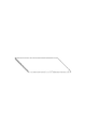
・上記プレートは、各々のプレートに1対の溝(図6)が設けられた6枚のプレートつまり主プレートからなる第1のグループと、残りのプレート(図7)で構成されるプレートつまり副プレートからなる第2のグループとに分割され、
・上記箱構造は、単層壁であって、各壁が上記主プレート(図6)のうちの1枚からなる壁、および/または複層壁であって、各壁が上記主プレートのうちの1枚と、上記副プレートのうちの少なくとも1枚とで作製される壁を備え、
・上記箱構造は、少なくとも1枚の複層壁を有し(図7、8、9)、
・上記箱構造は、まず上記6枚の主プレート、次に、上記副プレートのうちの少なくとも1枚のプレートを一緒に接合して組み立てられ、閉鎖される(図24、25、26、27、28、29)
ことを特徴とする、
接合構築システムからなる。
According to a first aspect, the present invention provides a joint construction system capable of assembling and securely closing a box structure, wherein the joint construction system comprises at least seven plates.
The above plate is a plate or sub-plate composed of a first group of six plates or main plates each having a pair of grooves (FIG. 6) in each plate and the remaining plates (FIG. 7). Divided into a second group of plates,
The box structure is a single-layer wall, each wall is a wall made of one of the main plates (FIG. 6) and / or a multi-layer wall, and each wall is one of the main plates And a wall made of at least one of the sub-plates,
The box structure has at least one multilayer wall (FIGS. 7, 8, and 9),
The box structure is assembled by first joining the six main plates and then joining at least one of the sub-plates together (FIGS. 24, 25, 26, 27, 28, 29)
It is characterized by
Consists of a joint construction system.
これはつまり、
a)最後の辺が、2ステップで2つの層に入り、
b)各辺を同じように実施でき、
c)各辺を3層以上で構成できる
ということである。
This means
a) The last side enters two layers in two steps,
b) Each side can be implemented in the same way,
c) Each side can be composed of three or more layers.
全般的に上記プレートすべてに係るもう1つの態様によれば、
・木材、プラスチック、ガラス、金属、コンクリート、石、およびこれらを任意に組み合わせたものなど、何らかの剛性材料で作製するか、又は切断若しくは溶融物の取り付けなどによって作製でき、切断、成形、組立(図16、17)、成形など、任意の方法で用意できる。
・所定の自由な寸法でよい。
・内側および/または外側の周囲を両エッジを横断してよい線とともに不規則な形状にも切断し、両エッジに溝を施してエッジの一部を取り除き、残りの部分が構造の気密性を保つのに十分なようにすることができる(図16、17)。
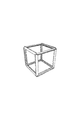
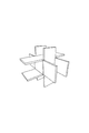
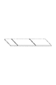
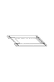
・フレーム形状によって内側のエッジにも溝を付けることができる(図14)。この選択肢によって、8枚のプレートを使用する本棚(図35)のような複数の箱構造を構築することができる。
・場合によって上記プレートを厚みのあるものにしてもよい(図11)。
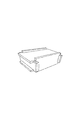
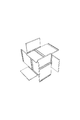
・上記プレートを、4つ角の上面で小部分を取り除いて、様々な構造を積み重ねられるようにすることができる(図33)。
According to another aspect that generally relates to all of the above plates,
・ Made of any rigid material such as wood, plastic, glass, metal, concrete, stone, and any combination of these, or can be made by cutting or attaching melts, etc. 16, 17), and can be prepared by any method such as molding.
-It may be a predetermined free dimension.
- also cut the inner and / or around the outer irregular shape with may lines across both edges, removing a portion of the edge is subjected to groove on both edges, the rest of the airtightness of the structure It can be sufficient to keep (FIGS. 16 and 17).
- Frame shape Therefore also the inside of the edge can be attached to the groove (Figure 14). With this option, a plurality of box structures such as a bookshelf (FIG. 35) using eight plates can be constructed.
MAY what a thick the plates optionally, (Figure 11).
· The plates, by removing a small portion at the top surface of the four corners, can be made to be stacked a variety of structures (Figure 33).
上記主プレートに係るもう1つの態様によれば、
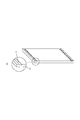
・各主プレートに、嵌合するようになっているプレートのエッジを受け入れるように構成された少なくとも1対の対面する平行な溝を備える:図6(1)。
・各主プレートを、フレーム形態に構成したのち、内部を空洞にして、プレート内側のエッジも外側のエッジも溝と連結するようにできる(図4、5、17、35)。
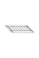
・各主プレートを、溝とは反対側の面に、1対の副プレートを受け入れるように構成された追加の対の溝を備えることができる(図19、20)。
・様々な構造を互いにうまく連結して、何枚かのプレートを共通のものにできるということであり、この場合、各構造を「節」と考えなければならない。
According to another aspect of the main plate,
Each main plate is provided with at least one pair of facing parallel grooves configured to receive the edges of the plates adapted to fit: FIG. 6 (1).
· Each main plate, after constituting the frame form, the internal and the cavity can be as plate inner edge is also connected to the outer edge also grooves (Fig. 4,5,17,35).
· Each main plate, the grooves on the opposite side, may comprise a configured groove of the additional pairs to receive a pair sub plates (19 and 20).
- various structures successfully combine with each other, it means that several sheets of plate can be a common thing, in this case, must be considered as a "section" of each structure.
上記副プレートに係るもう1つの態様によれば、
・少なくとも1枚の副プレートを使用して、上記箱構造を閉鎖しなければならない。これらのプレートは、異なる理由でも用いられるプレートの種類および数量にかかわらず、この主機能を有する。
・各副プレートを、任意に、主プレートとして構成することができ、その後に1対の上記溝を備えることもできる。これによって、単一のモジュールを使用して永久的な係合構造を構築することができる(図30、31、32)。
・副プレートを、2つの特定の溝を備えた各主プレートの対で、ロック機能を実行することができる:図19(7)、20。
・各副プレートは、機能上または美観的な理由で厚みに起伏を持たせて成形してもよい(図11)。
According to another aspect of the sub-plate,
• The box structure must be closed using at least one secondary plate. These plates have this main function regardless of the type and quantity of plates used for different reasons.
- Each sub-plate, optionally, can be configured as the main plate, may be subsequently provided with a pair of said grooves. This allows a permanent engagement structure to be constructed using a single module (FIGS. 30, 31, 32).
- sub-plate, a pair of the main plate with two specific groove, it is possible to perform the locking function: 19 (7), 20.
Each sub-plate may be shaped with an undulating thickness for functional or aesthetic reasons (FIG. 11).
上記溝に係るもう1つの態様によれば、
・溝は、係合するように配置され、プレートのエッジを受け入れるように構成され、各主プレートの面の対面する2辺で、直線的かつ平行な対になるように構成される:図6(1)。
・溝の幅は、受け入れることになっている単層壁または複層壁の厚みの合計に等しい:図23(10)。
・溝は、様々に描かれた断面を有することができる。
According to another aspect of the groove,
The grooves are arranged to engage and are configured to receive the edges of the plate, and are configured to be linear and parallel pairs on the two opposite sides of each main plate face: FIG. (1).
The width of the groove is equal to the sum of the thicknesses of the single or multi-layer walls that are to be accepted: FIG. 23 (10).
The groove can have variously drawn cross sections.
上記複層壁に係るもう1つの態様によれば、
・複層壁の全体の厚みを、単層壁の厚みに等しくすることができる:図18(5)。このようにすると、全プレートの溝は等しくなるが、主プレートの厚みは同じではない。
・複層壁は、主プレートすべてが同じ厚みであってよい:図18(6)。このようにすると、プレートの溝は、同じ幅ではない。
According to another aspect of the upper Kifuku layer wall,
-The total thickness of the multilayer wall can be made equal to the thickness of the single layer wall: Fig. 18 (5). In this way, the grooves of all the plates are equal, but the thickness of the main plate is not the same.
-The multi-layer wall may have the same thickness on all the main plates: FIG. 18 (6). In this way, the grooves in the plate are not the same width.
任意で備える追加手段に係るもう1つの態様によれば、
・上記システムには、南京錠、または針を微細な穴に通すことのできる留め金のような、分解が難しい安全および秘密を守るための追加手段を備えることができる(図38)。
According to another aspect of the optional additional means,
• The system can be equipped with additional means to protect safety and secrets that are difficult to disassemble, such as padlocks or clasps that allow needles to pass through fine holes (FIG. 38).
組立手順に係るもう1つの態様によれば、
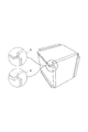
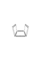
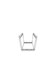
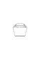
・単層または複層である最初の5枚の壁をそれぞれ、溝の中にエッジを挿入して組み立てるようにする(図24から26)。
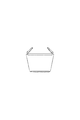
・複層壁でなければならない最後の壁の主プレートを、まだ自由な状態の溝に挿入し、その後に係合させるようにする(図27)。
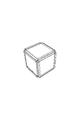
・少なくとも1枚の副プレートを、溝の残りの自由なスペースに挿入しなければならず、構造をしっかりと閉鎖する(図28、29)。
According to another aspect of the assembly procedure,
- is a single layer or multiple layer first five walls, respectively, to assemble by inserting the edges into the groove (26 Fig. 24).
• Insert the main plate of the last wall, which must be a multi-layer wall, into the still free groove and then engage (Fig. 27).
• At least one minor plate must be inserted into the remaining free space of the groove, firmly closing the structure (FIGS. 28, 29).
いくつかの実施形態では、以下の試作品を作製した。
・玩具(図30、31、32)。
In some embodiments, the following prototypes were created.
-Toys (FIGS. 30, 31, 32).
この玩具は、12枚のプレートすべてが完全に等しい(72x60x3mm)3Dパズルである。この玩具は、ABS樹脂または木材で永久に作製できる単一の素子からなり、このゲームでは、単一のプレートが無限に組み立てられ、様々な構成に作ることができる。
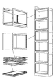
・全体をコンパクトにできる(50x35x3cm)モジュール式本棚(図34)。この本棚では、2枚の副プレートと、フレーム形状の6枚の主プレートのうちの2枚との8枚のプレートからなる方法を使用する。
・プーフまたはモジュール式本棚(図4)に戻せる、全体をコンパクトにできる小テーブル。これは、木材またはプレキシガラスで、多くの構成で実現可能である。このテーブルは、立方体(1辺42cm)で、そのままのプレートまたはフレーム形状もしくは混合形状のプレートを有する。
This toy is a 3D puzzle where all 12 plates are exactly equal (72x60x3mm). This toy consists of a single element that can be permanently made of ABS resin or wood, and in this game a single plate can be assembled indefinitely and made in various configurations.
-A modular bookshelf that can be made compact (50x35x3cm) (Figure 34). This book shelf uses a method comprising eight plates, two sub-plates and two of the six frame-shaped main plates.
-A small table that can be returned to the pouf or modular bookshelf (Figure 4) and made compact. This can be achieved in many configurations with wood or plexiglass. This table is a cube (42 cm per side) and has a plate as it is or a frame or mixed shape plate .
本発明は、広範囲にわたる建設的な方法を有し、多くの予測不可能な用途に向いている。当該技術には、以下のいくつかの利点がある。
・連結装置を使用せずにこの技術が簡易になる。
・どのような種類の剛性材料にも適用可能である。
・必要な機械加工工程および労力が最小である。
・膨大な加工損失を生み出さない。
・ほぼそのままの素子が形成され、再利用性およびリサイクル性が高い。
・小型化できる可能性が高く、貯蔵および輸送に多くの利点がある。
・製造過程で組み立てる必要がない。
・組立が実に簡易で極めて迅速である。
・成形可能であり、無制限のデザイン構成に向いている。
・いくつかの建設的な方法がある。
・複雑な構造に対して節としての重要な機能を有する。
・3次元に沿った高耐性のシールを有する。
The present invention has a wide range of constructive methods and is suitable for many unpredictable applications. The technology has several advantages:
-This technology is simplified without using a coupling device.
-Applicable to any kind of rigid material.
• Minimum machining steps and effort required.
・ Does not generate huge processing loss.
-Almost the same element is formed, and reusability and recyclability are high.
・ There is a high possibility of miniaturization, and there are many advantages in storage and transportation.
・ There is no need to assemble in the manufacturing process.
-Assembly is really simple and extremely quick.
・ Moldable and suitable for unlimited design configurations.
There are several constructive ways.
・ It has an important function as a clause for complex structures.
• Has a highly resistant seal along the 3rd dimension.
Claims (11)
前記プレートは、各々のプレートに1対の溝が設けられた6枚の主プレートからなる第1のグループと、残りのプレートで構成される副プレートからなる第2のグループとに分割され、
前記箱構造は、単層壁であって、各壁が前記主プレートのうちの1枚からなる壁、および/または複層壁であって、各壁が前記主プレートのうちの1枚と、前記副プレートのうちの少なくとも1枚とで作製される壁を備え、
前記箱構造は、少なくとも1枚の複層壁を有するものであり、
前記各プレートのエッジを他のプレートの溝に挿入して前記6枚の主プレートを結合するステップと、
前記副プレートのうちの少なくとも1枚を、前記主プレートの前記溝の前記主プレートの前記溝の残りの自由スペースに挿入するステップとによって、
前記箱構造が、組み立てられ、閉鎖される
ことを特徴とする箱構造の接合構築方法。 A joining construction method of the box structure comprising at least 7 plates,
The plates are divided into a first group consisting of six main plates each having a pair of grooves in each plate, and a second group consisting of sub-plates composed of the remaining plates,
The box structure is a single-layer wall, each wall is a wall consisting of one of the main plates, and / or a multi-layer wall, each wall being one of the main plates; Comprising a wall made of at least one of the sub-plates;
The box structure is to have at least one double-wall,
Inserting the edges of each plate into the grooves of another plate to join the six main plates ;
Inserting at least one of the sub-plates into the remaining free space of the groove of the main plate of the groove of the main plate;
The box structure is assembled and closed. A method for joining and constructing a box structure .
請求項1に記載の箱構造の接合構築方法。 The box structure joint construction method according to claim 1, wherein the plate is made of wood, plywood, glass, stone, metal, plastic, and a rigid material that combines these.
請求項1または2に記載の箱構造の接合構築方法。 The box-structure joint construction method according to claim 1, wherein the plate has a frame shape, whereby a groove for receiving the plate can be attached to an inner edge.
請求項3に記載の箱構造の接合構築方法。 The box structure joint construction method according to claim 3, wherein a part of the edge and / or a part of the groove is removed along the side of the plate.
請求項1ないし4のいずれかに記載の箱構造の接合構築方法。 2. The main plate comprises at least one pair of grooves, each groove configured to receive one edge of the main plate, or further to receive at least one edge of the sub-plate. 5. A box-structured joint construction method according to any one of items 4 to 4.
請求項1ないし5のいずれかに記載の箱構造の接合構築方法。 The main plate includes two additional appropriate grooves on a surface opposite to a surface on which grooves are already provided and on two sides perpendicular to the grooves. 2. A method for constructing a joint having a box structure according to 1 .
請求項1ないし6のいずれかに記載の箱構造の接合構築方法。 The box-structure joint construction method according to any one of claims 1 to 6, wherein the main plate extending in a direction perpendicular to the groove includes an additional pair of grooves suitable for receiving another plate.
請求項1ないし6のいずれかに記載の箱構造の接合構築方法。 The pair of grooves are parallel, and each of the pairs is configured to receive one edge of the single wall or one edge of the multilayer wall. Box construction method .
請求項1ないし6のいずれかに記載の箱構造の接合構築方法。 The box structure joint construction method according to any one of claims 1 to 6, wherein the sub plate performs a role of each main plate provided with appropriate two grooves in a suitable shape.
請求項1ないし9のいずれかに記載の箱構造の接合構築方法。 The box structure joint construction method according to claim 1, wherein the sub-plate is completely the same as the main plate and has the same groove.
請求項1ないし10のいずれかに記載の箱構造の接合構築方法。 The box structure joint construction method according to any one of claims 1 to 10, wherein the multilayer wall box structure is provided by a spring hinge, a padlock, a clasp, or another fixing means.
Applications Claiming Priority (1)
| Application Number | Priority Date | Filing Date | Title |
|---|---|---|---|
| PCT/IT2009/000410 WO2011033534A1 (en) | 2009-09-15 | 2009-09-15 | Joint building system for box structures |
Publications (2)
| Publication Number | Publication Date |
|---|---|
| JP2013504401A JP2013504401A (en) | 2013-02-07 |
| JP5902090B2 true JP5902090B2 (en) | 2016-04-13 |
Family
ID=41343469
Family Applications (1)
| Application Number | Title | Priority Date | Filing Date |
|---|---|---|---|
| JP2012529409A Expired - Fee Related JP5902090B2 (en) | 2009-09-15 | 2009-09-15 | Box structure joint construction method |
Country Status (12)
| Country | Link |
|---|---|
| US (1) | US9187208B2 (en) |
| EP (1) | EP2477903B1 (en) |
| JP (1) | JP5902090B2 (en) |
| CN (1) | CN102574609B (en) |
| BR (1) | BR112012005675A2 (en) |
| CA (1) | CA2774123C (en) |
| DK (1) | DK2477903T3 (en) |
| ES (1) | ES2466342T3 (en) |
| IN (1) | IN2012DN03013A (en) |
| PL (1) | PL2477903T3 (en) |
| RU (1) | RU2511501C2 (en) |
| WO (1) | WO2011033534A1 (en) |
Families Citing this family (16)
| Publication number | Priority date | Publication date | Assignee | Title |
|---|---|---|---|---|
| CN104015976A (en) * | 2014-06-19 | 2014-09-03 | 昆山英博尔电子科技有限公司 | Assembly material box |
| CN104691985A (en) * | 2015-02-13 | 2015-06-10 | 韩永发 | Container capable of being rapidly disassembled and rapidly unloading materials |
| US10744419B2 (en) * | 2017-06-09 | 2020-08-18 | Qun Xia | Modular panel interlocking and reinforcing mechanism for building enclosures |
| USD873566S1 (en) * | 2018-05-18 | 2020-01-28 | Anthony Lewis | Modular crate |
| CN109533565B (en) * | 2018-11-06 | 2024-08-23 | 安徽信德化纤有限公司 | Chemical fiber collecting box |
| CN109606898A (en) * | 2018-12-26 | 2019-04-12 | 珠海浩云电气有限公司 | A kind of assembled packaging box |
| JP7237270B2 (en) * | 2019-01-17 | 2023-03-13 | 遠藤 祥 | Assembled housing using only one size of member |
| WO2020243025A1 (en) * | 2019-05-24 | 2020-12-03 | Degrees of Freedom LLC | Origami-inspired enclosure, table, and lamp |
| IT201900019754A1 (en) * | 2019-10-24 | 2021-04-24 | Gruppo Poligrafico Tiberino Srl | PERFECTED REMOVABLE BOX |
| FR3103469A1 (en) * | 2019-11-25 | 2021-05-28 | François GELI | Glass food container, lightened by bio-based plates, and can be free of non-biodegradable plastics |
| US11352785B2 (en) * | 2020-01-31 | 2022-06-07 | B & B Flying Service, Inc. | Construction block units |
| USD965364S1 (en) * | 2021-02-05 | 2022-10-04 | Baltsum, SIA | Furniture set |
| USD1015007S1 (en) * | 2021-03-22 | 2024-02-20 | 6x6 Designs LLC | Record storage cabinet |
| USD998930S1 (en) * | 2021-09-27 | 2023-09-12 | Caoxian Shuofan Trading Co., Ltd. | Pet cremation urn box |
| TWI827350B (en) * | 2022-11-08 | 2023-12-21 | 台泥儲能科技股份有限公司 | Cabinet unit and cabinet system |
| KR102728988B1 (en) * | 2024-01-26 | 2024-11-13 | 김대식 | Embedded form and method for concrete foundation of road facility using the same |
Family Cites Families (24)
| Publication number | Priority date | Publication date | Assignee | Title |
|---|---|---|---|---|
| US756338A (en) * | 1903-03-24 | 1904-04-05 | Clinton A Hanks | Knockdown box. |
| US1209027A (en) * | 1916-01-11 | 1916-12-19 | Paul R Quade | Knockdown shipping-box. |
| GB969578A (en) * | 1962-11-05 | 1964-09-09 | Myles Burton | Improvements in or relating to packing cases |
| GB987194A (en) * | 1963-06-10 | 1965-03-24 | Robert Miocque | Improvements in or relating to collapsible cases or containers |
| US3261492A (en) * | 1964-05-15 | 1966-07-19 | Potlatch Forests Inc | Wooden box construction |
| US3410441A (en) * | 1966-06-29 | 1968-11-12 | Jeff S. Rhyne | Container |
| US3700134A (en) * | 1970-06-04 | 1972-10-24 | Russell T Blanchard | Collapsible container |
| US3713718A (en) * | 1971-01-18 | 1973-01-30 | D Lucci | Cabinet construction |
| US3902637A (en) * | 1973-05-02 | 1975-09-02 | Philip K Scheeler | Toiletry dispenser |
| US4012090A (en) * | 1975-11-05 | 1977-03-15 | Raymond Pfeifer | Knockdown put-together drawer |
| CH610193A5 (en) * | 1977-02-16 | 1979-04-12 | Werner Blaser | Item of dismantlable furniture having five rectangular panels forming its outer surfaces |
| US4082356A (en) * | 1977-02-25 | 1978-04-04 | Karin Ruth Johnson | Educational puzzle chair |
| US4262605A (en) * | 1979-05-14 | 1981-04-21 | Sokol Filip L | Nestable unitized shelving system |
| JPS57169397U (en) * | 1981-04-17 | 1982-10-25 | ||
| US4561554A (en) * | 1981-09-25 | 1985-12-31 | Swincicki Edmund J | Container for produce, fruits groceries and the like |
| GB2155439B (en) * | 1984-03-07 | 1987-09-16 | Smith Bros | Improvements in or relating to collapsible containers |
| US5743421A (en) * | 1995-11-22 | 1998-04-28 | Gonzalez; Carlos | Instant crate |
| US6558222B1 (en) * | 1997-02-28 | 2003-05-06 | Paul Thomas Maddock | Panelling and supports for interconnected toy blocks |
| US6309039B1 (en) * | 2000-02-24 | 2001-10-30 | Gh Canada Inc. | Container with bottom panel and method of making same |
| US6497018B1 (en) * | 2001-08-27 | 2002-12-24 | Jin-Hsien Chiu | Structure of a coffin |
| JP2005102800A (en) * | 2003-09-29 | 2005-04-21 | Reiko Sato | Ornamental coffin |
| US20080042532A1 (en) * | 2006-08-16 | 2008-02-21 | Crabtree Phillip C | Cabinet system and method of assembling the same |
| US7988517B2 (en) * | 2007-05-11 | 2011-08-02 | Forrest Frederick Bishop | Construction and gaming cubes |
| US20100093257A1 (en) * | 2008-10-14 | 2010-04-15 | Elliott Joseph T | Ready to assemble structural system |
-
2009
- 2009-09-15 WO PCT/IT2009/000410 patent/WO2011033534A1/en not_active Ceased
- 2009-09-15 EP EP09741467.6A patent/EP2477903B1/en not_active Not-in-force
- 2009-09-15 RU RU2012115482/12A patent/RU2511501C2/en not_active IP Right Cessation
- 2009-09-15 PL PL09741467T patent/PL2477903T3/en unknown
- 2009-09-15 CN CN200980161471.8A patent/CN102574609B/en not_active Expired - Fee Related
- 2009-09-15 CA CA2774123A patent/CA2774123C/en not_active Expired - Fee Related
- 2009-09-15 BR BR112012005675A patent/BR112012005675A2/en not_active Application Discontinuation
- 2009-09-15 ES ES09741467.6T patent/ES2466342T3/en active Active
- 2009-09-15 US US13/496,443 patent/US9187208B2/en not_active Expired - Fee Related
- 2009-09-15 JP JP2012529409A patent/JP5902090B2/en not_active Expired - Fee Related
- 2009-09-15 DK DK09741467.6T patent/DK2477903T3/en active
-
2012
- 2012-04-09 IN IN3013DEN2012 patent/IN2012DN03013A/en unknown
Also Published As
| Publication number | Publication date |
|---|---|
| CA2774123C (en) | 2015-01-27 |
| PL2477903T3 (en) | 2014-08-29 |
| CN102574609B (en) | 2015-09-16 |
| US9187208B2 (en) | 2015-11-17 |
| EP2477903A1 (en) | 2012-07-25 |
| EP2477903B1 (en) | 2014-02-26 |
| ES2466342T3 (en) | 2014-06-10 |
| CA2774123A1 (en) | 2011-03-24 |
| WO2011033534A1 (en) | 2011-03-24 |
| BR112012005675A2 (en) | 2016-03-01 |
| IN2012DN03013A (en) | 2015-07-31 |
| US20120175377A1 (en) | 2012-07-12 |
| DK2477903T3 (en) | 2014-06-16 |
| CN102574609A (en) | 2012-07-11 |
| RU2511501C2 (en) | 2014-04-10 |
| JP2013504401A (en) | 2013-02-07 |
| RU2012115482A (en) | 2013-10-27 |
Similar Documents
| Publication | Publication Date | Title |
|---|---|---|
| JP5902090B2 (en) | Box structure joint construction method | |
| CN105874223B (en) | Combination product and the method for assembling the product | |
| JP6396474B2 (en) | Assembly product and method for assembling the assembly product | |
| US9909604B1 (en) | System and method of securing adjoining walls utilizing keys | |
| US10086304B1 (en) | Modular panel system for interactive play or display | |
| CN107788706A (en) | Baffle connecting block and baffle | |
| CN205885095U (en) | Connect locking device and use box of connecting locking device | |
| US20190078598A1 (en) | Panel lock construct | |
| CA2248428A1 (en) | Space divider panel | |
| JP3177322U (en) | Simple partition made of reinforced cardboard | |
| CN210471441U (en) | Expandable storage rack | |
| CN212260862U (en) | Structure of foldable ecological wood locker | |
| TWI659713B (en) | Cabinet structure and frame elements thereof | |
| JP3133038U (en) | Creative assembly furniture | |
| JP2011206086A (en) | Knockdown furniture | |
| US12297642B1 (en) | Modular interlocking assembly system | |
| JP6748751B1 (en) | Unit furniture | |
| KR101471565B1 (en) | Modular cases for holding articles | |
| CA2775099A1 (en) | Collapsible box made of identical panels | |
| KR20120028417A (en) | A section panel for collection box and section apparatus for the same | |
| JP3189568U (en) | Plate material connection cassette structure | |
| JP2005027758A (en) | Foldable bookcase | |
| CA2978912A1 (en) | Panel lock construct | |
| TW202325185A (en) | Varied DIY combinable rack structure in which the arrangement of the frame bodies can be freely changed without destroying and reassembling the frame bodies | |
| JPS62254710A (en) | Cabinet constitutional body |
Legal Events
| Date | Code | Title | Description |
|---|---|---|---|
| A977 | Report on retrieval |
Free format text: JAPANESE INTERMEDIATE CODE: A971007 Effective date: 20130930 |
|
| A601 | Written request for extension of time |
Free format text: JAPANESE INTERMEDIATE CODE: A601 Effective date: 20140204 |
|
| A602 | Written permission of extension of time |
Free format text: JAPANESE INTERMEDIATE CODE: A602 Effective date: 20140212 |
|
| A521 | Request for written amendment filed |
Free format text: JAPANESE INTERMEDIATE CODE: A523 Effective date: 20140226 |
|
| A131 | Notification of reasons for refusal |
Free format text: JAPANESE INTERMEDIATE CODE: A131 Effective date: 20141007 |
|
| A601 | Written request for extension of time |
Free format text: JAPANESE INTERMEDIATE CODE: A601 Effective date: 20141222 |
|
| A521 | Request for written amendment filed |
Free format text: JAPANESE INTERMEDIATE CODE: A523 Effective date: 20150121 |
|
| A131 | Notification of reasons for refusal |
Free format text: JAPANESE INTERMEDIATE CODE: A131 Effective date: 20150421 |
|
| A521 | Request for written amendment filed |
Free format text: JAPANESE INTERMEDIATE CODE: A523 Effective date: 20150507 |
|
| A131 | Notification of reasons for refusal |
Free format text: JAPANESE INTERMEDIATE CODE: A131 Effective date: 20150805 |
|
| A521 | Request for written amendment filed |
Free format text: JAPANESE INTERMEDIATE CODE: A523 Effective date: 20151105 |
|
| A601 | Written request for extension of time |
Free format text: JAPANESE INTERMEDIATE CODE: A601 Effective date: 20151105 |
|
| TRDD | Decision of grant or rejection written | ||
| A01 | Written decision to grant a patent or to grant a registration (utility model) |
Free format text: JAPANESE INTERMEDIATE CODE: A01 Effective date: 20160209 |
|
| A61 | First payment of annual fees (during grant procedure) |
Free format text: JAPANESE INTERMEDIATE CODE: A61 Effective date: 20160309 |
|
| R150 | Certificate of patent or registration of utility model |
Ref document number: 5902090 Country of ref document: JP Free format text: JAPANESE INTERMEDIATE CODE: R150 |
|
| LAPS | Cancellation because of no payment of annual fees |