JP5901552B2 - Fall detector and packing device provided with the same - Google Patents
Fall detector and packing device provided with the same Download PDFInfo
- Publication number
- JP5901552B2 JP5901552B2 JP2013032787A JP2013032787A JP5901552B2 JP 5901552 B2 JP5901552 B2 JP 5901552B2 JP 2013032787 A JP2013032787 A JP 2013032787A JP 2013032787 A JP2013032787 A JP 2013032787A JP 5901552 B2 JP5901552 B2 JP 5901552B2
- Authority
- JP
- Japan
- Prior art keywords
- fall
- container
- fall detector
- detector
- packing box
- Prior art date
- Legal status (The legal status is an assumption and is not a legal conclusion. Google has not performed a legal analysis and makes no representation as to the accuracy of the status listed.)
- Expired - Fee Related
Links
Images


Landscapes
- Details Of Rigid Or Semi-Rigid Containers (AREA)
Description
本発明は、梱包箱の転倒の有無と転倒方向を検知するため転倒検知器とこれを備えた梱包装置に関するものである。 The present invention relates to a tipping detector and a packing device provided with the tipping detector for detecting the presence or absence and the direction of the tipping of the packing box.
例えば、複写機やプリンター等の製品を工場からユーザー先まで輸送する場合、製品は段ボール箱等の梱包箱に梱包された状態で輸送されるが、この場合、所定の梱包基準に基づいて設計された緩衝部材を用いて製品が梱包されている。ここで、緩衝部材は過剰なスペックにならないようにコストも意識して設計されている。 For example, when products such as copiers and printers are transported from the factory to the user, the products are transported in the state of being packed in a packing box such as a cardboard box. In this case, the product is designed based on a predetermined packing standard. The product is packed using the cushioning member. Here, the shock-absorbing member is designed in consideration of cost so as not to have excessive specifications.
しかし、市場では梱包基準以上の過酷な条件で製品が輸送されることが多く、梱包箱が横に倒された状態で放置され、この梱包箱が振動を受けたり、落下したような場合には、内部の製品が損傷することがある。梱包箱の外ケースは圧縮強度を考慮したスペックになっているため、梱包箱の外観からだけでは輸送時の製品の状態を判断することができない。 However, in the market, products are often transported under harsh conditions that exceed the packing standards, and if the packing box is left sideways and the packing box is subjected to vibration or falls, The internal product may be damaged. Since the outer case of the packing box has a specification considering the compressive strength, the state of the product at the time of transportation cannot be determined only from the appearance of the packing box.
そこで、輸送中に製品や梱包箱が転倒したか否かを検知する転倒検知器を製品や梱包箱に設置することが行われている。 Therefore, a fall detector that detects whether or not the product or packaging box has fallen during transportation is installed in the product or packaging box.
例えば、特許文献1には、製品や梱包箱が傾斜限界を超えたときにインジケータが保持ガイドから外れるようにした転倒検知器が提案されている。より詳細には、インジケータは、傾斜したときに保持ガイドにおいて転動する形状の第1部分と、該第1部分よりも小さくて当該第1部分の転動を妨げない形状の第2部分とで構成され、通常は第1部分と第2部分とが結合しており、これらが衝撃を受けた場合に分離するようになっている。このような転倒検知器によれば、製品の転倒の有無と製品が衝撃を受けたか否かを検知することができる。
For example,
しかしながら、特許文献1において提案された転倒検知器によれば、製品や梱包箱の転倒の有無や製品が衝撃を受けたか否かを検知することができるものの、製品や梱包箱の転倒方向は検知することができない。
However, according to the fall detector proposed in
本発明は上記問題に鑑みてなされたもので、その目的とする処は、梱包箱の転倒の有無と転倒方向を検知することができる転倒検知器及びこれを供え他梱包装置を提供することにある。 The present invention has been made in view of the above problems, and the object of the present invention is to provide a tipping detector capable of detecting whether or not the packing box has fallen and the tipping direction, and to provide other packing devices. is there.
上記目的を達成するため、請求項1記載の発明は、梱包箱又は該梱包箱が載置されるパレットに設置されて梱包箱の転倒の有無と転倒方向を検知するための転倒検知器を、上端が開口した容器を透明なケース内に収納し、該ケース内の前記容器との間の空間を仕切板によって区画して周方向に複数の室を形成し、前記容器内に流動体を収容して構成したことを特徴とする。
In order to achieve the above object, the invention according to
請求項2記載の発明は、請求項1記載の発明において、前記容器を上方に向かって先細り形状に成形するとともに、その上端を前記仕切板の上端よりも高い位置で開口させたことを特徴とする。
The invention according to
請求項3記載の発明は、請求項1又は2記載の発明において、前記ケース内の前記容器との間の空間を4枚の前記仕切板によって4つの室に区画したことを特徴とする。 A third aspect of the invention is characterized in that, in the first or second aspect of the invention, a space between the case and the container is partitioned into four chambers by the four partition plates.
請求項4記載の発明は、請求項1〜3の何れかに記載の発明において、前記ケースの外周に位置決めリブを突設したことを特徴とする。 According to a fourth aspect of the present invention, in the invention according to any one of the first to third aspects, a positioning rib projects from the outer periphery of the case.
請求項5記載の梱包装置は、請求項1〜4の何れかに記載された転倒検知器を備えることを特徴とする。 A packaging device according to a fifth aspect includes the fall detector according to any one of the first to fourth aspects.
請求項6記載の発明は、請求項5記載の発明において、パレットの桁に前記点灯検知器を収納し、前記桁に視認用の窓を形成したことを特徴とする。 A sixth aspect of the invention is characterized in that, in the fifth aspect of the invention, the lighting detector is housed in a pallet girder and a visual window is formed in the girder.
本発明によれば、輸送中に梱包箱が転倒した場合、該梱包箱又はパレットに設置された転倒検知器も転倒し、その容器に収容された流動体が上端の開口部から外部へとこぼれ出し、梱包箱を正規の姿勢に復帰させたときに転倒検知器も正規の姿勢に復帰し、該転倒検知器の容器の外部へとこぼれ出した流動体がケース内の仕切られた複数の室の何れかに溜まる。従って、転倒検知器の容器の外部に流動体がこぼれ出しているか否かによって梱包箱の転倒の有無を検知することができるとともに、梱包箱の転倒が検知された場合、流動体が転倒検知器のケース内の複数の室のうちのどの室に溜まっているかによって転倒した方向を検知することができる。 According to the present invention, when the packaging box falls during transportation, the fall detector installed on the packaging box or pallet also falls, and the fluid contained in the container spills out from the opening at the upper end. When the packing box is returned to the normal posture, the fall detector also returns to the normal posture, and the fluid that has spilled out of the fall detector container is divided into a plurality of compartments in the case. It collects in either. Therefore, it is possible to detect whether or not the packaging box has fallen depending on whether or not the fluid has spilled outside the container of the fall detector, and when the fall of the packaging box is detected, the fluid will fall. The direction of falling can be detected depending on which of the plurality of chambers in the case is accumulated.
又、ケースの外周に突設された位置決めリブを梱包箱又はパレットニ形成された係合溝に係合させることによって、転倒検知器を梱包箱に対して周方向において所定の向きに正確に位置決めした状態で設置することができ、梱包箱の転倒方向を正確に検知することができる。 In addition, the fall detector is accurately positioned in a predetermined direction in the circumferential direction with respect to the packing box by engaging positioning ribs provided on the outer periphery of the case with the engaging grooves formed in the packing box or pallet. It can be installed in a state, and the falling direction of the packaging box can be accurately detected.
以下に本発明の実施の形態を添付図面に基づいて説明する。 Embodiments of the present invention will be described below with reference to the accompanying drawings.
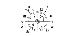
図1は本発明に係る転倒検知器の正面図、図2は同転倒検知器の平面図、図3は図2のA−A線断面図であり、図示の転倒検知器1においては、上面が閉じられた円筒状の透明なケース2の内部に円錐筒状の容器3が下方から圧入されて収容されている。ここで、容器3は上方に向かって先細りの逆漏斗状に成形されており、その上端には開口部3aが形成されている。そして、この容器3の内部には、図3に示すように流動体として砂4が収容されている。尚、容器3に収容する流動体としては、砂4以外に液体(好ましくは有色のもの)等を用いても良い。
1 is a front view of a fall detector according to the present invention, FIG. 2 is a plan view of the fall detector, and FIG. 3 is a cross-sectional view taken along line AA of FIG. 2. In the
そして、ケース2の内部には容器3との間に空間が形成されるが、この空間は、図2に示すように、平面視十字状に配置された仕切板5によって区画され、空間には同じ容積の4つの室S1,S2,S3,S4が周方向に形成されている。ここで、図1及び図3に示すように、容器3の上端は仕切板5の上端よりも高い位置あり、この上端の開口部3aは仕切板5の上方において開口している。
In addition, a space is formed between the
又、本実施の形態に係る転倒検知器1においては、ケース2の上端外周(具体的には、室S1が形成された部位)に、上下方向に長い矩形プレート状の位置決めリブ6が径方向外方に向かって突設されている。
Further, in the
次に、以上のように構成された転倒検知器1の設置構造を図4〜図6に基づいて以下に説明する。
Next, the installation structure of the
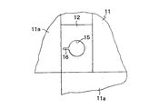
図4は本発明に係る転倒検知器が設置されたパレットのフランジ片を展開した状態の一部を破断して示す平面図、図5は同パレットの正面図(図4の矢視B方向の図)、図6は図4のC部拡大詳細図であり、図示のパレット10は、製品が梱包された不図示の梱包箱を載置するためのものであって、矩形状の合板製のベース11を木製ブロック状の複数(図示例では9個)の桁(スペーサ)12で支持するとともに、これらの桁12同士の下面を木製の渡し部材13によって連結することによって構成されている。尚、ベース11の上面には段ボール製の底板11Aが載置されており、この底板11Aの周囲には、上方へと折り曲げ可能な4つのフランジ片11aがそれぞれ形成されており、各フランジ片11aには、当該フランジ片11aを不図示の梱包箱に連結するための不図示のジョイントを通すための長孔14がそれぞれ形成されている。
FIG. 4 is a plan view showing a state in which a flange piece of a pallet on which a fall detector according to the present invention is installed is broken, and FIG. 5 is a front view of the pallet (in the direction of arrow B in FIG. 4). FIG. 6 is an enlarged detail view of part C of FIG. 4, and the illustrated
本実施の形態では、複数の桁12の1つ(図4及び図5参照)には図6に示すような円穴15が形成されている。この円穴15は上方が開口する垂直な穴であって、その外周からは係合溝16が径方向外方に延びている。又、図5に示すように、円穴15が形成された桁12の側面(図5の手前側の面)には矩形の検知窓17が形成されている。
In the present embodiment, a
而して、1つの桁12に形成された円穴15には、図1〜図3に示す転倒検知器1が上方から差し込まれて収納されるとともに、そのケース2の外周に突設された位置決めリブ6が桁12に形成された前記係合溝16に係合する子とによって当該転倒検知器1の周方向の位置決めがなされる。
Thus, in the
以上のように1つの桁12の円穴15に転倒検知器1が収容されたパレット10のベース11上に不図示の梱包箱が載置されると、パレット10のベース11の周囲に形成されたフランジ片11aが垂直上方へと折り曲げられて梱包箱の外周面に当てられ、各フランジ片に形成された長孔14に挿通する不図示のジョイントによって各フランジ片11aが梱包箱の周面に連結されることによってパレット10が梱包箱の下面に連結されて一体化される。
As described above, when a not-illustrated packing box is placed on the
次の、パレット10の1つの桁12に収容された転倒検知器1の作用を図7に基づいて以下に説明する。尚、図7は本発明に係る転倒検知器の作用を説明する断面図であって、(a)は転倒時の状態、(b)は復帰時の状態をそれぞれ示す。
Next, the operation of the
製品が収容された梱包箱が例えば工場からユーザー先へと輸送される場合、その途中での該梱包箱の転倒の有無と転倒していた場合にはその転倒方向が転倒検知器1によって検知される。
When the packaging box containing the product is transported from the factory to the user, for example, if the packaging box has fallen in the middle and if it has fallen, its fall direction is detected by the
即ち、輸送中に梱包箱が転倒しなかった場合には、転倒検知器1も転倒しないため、容器に収容された砂4は該容器3の上端の開口部3aからケース2内の空間へと漏れ出ることがない。このため、転倒検知器1の4つの室S1〜S4には砂4が溜まっておらず(図3に示す状態)、このことによって梱包箱は輸送中に1回も転倒しなかったことが分かる。
That is, when the packing box does not fall during transportation, the
他方、輸送中に梱包箱が転倒した場合には、転倒検知器1も図7(a)に示すように転倒して真横を向くため、容器3内に収容されている砂4が該容器3の開口部3aから外部の空間へと漏れ出してケース2内の空間に溜まる。このような状態で梱包箱を正規の姿勢に復帰させると、転倒検知器1の容器3から漏れ出した砂4が梱包箱の転倒方向によって室S1〜S4の何れか1つに図7(b)に示すように溜まる。このため、転倒検知器1において砂4が複数の室S1〜S4のどの室に溜まっているかを判別することによって梱包箱の転倒方向を検知することができる。
On the other hand, when the packaging box falls during transportation, the
以上のように、本発明に係る転倒検知器1によれば、容器3の外部に砂4がこぼれ出しているか否かによって梱包箱の転倒の有無を検知することができるとともに、梱包箱の転倒が検知された場合、砂4が転倒検知器1のケース2内の複数の室S1〜S4のうちの何れに溜まっているかを判別することによって転倒した方向を検知することができる。そして、本実施の形態では、パレット10の転倒検知器1が設置される桁12の側面に検知窓17を形成したため、この検知窓17から砂4の状態を視認することによって梱包箱の転倒の有無と転倒方向をそのままの状態で検知することができる。
As described above, according to the overturn
又、本実施の形態では、転倒検知器1のケース2の外周に突設された位置決めリブ6をパレット10の桁12に形成された係合溝16に係合させるようにしたため、該転倒検知器1を梱包箱に対して所定の向きに正確に位置決めした状態で設置することができ、梱包箱の転倒方向を正確に検知することができる。
In this embodiment, since the positioning rib 6 protruding from the outer periphery of the
尚、以上の実施の形態では、転倒検知器1をパレット10の桁12に設置したが、転倒検知器1を梱包箱に直接設置するようにしても良い。
In the above embodiment, the
1 転倒検知器
2 転倒検知器のケース
3 転倒検知器の容器
3a 容器の開口部
4 砂(流動体)
5 転倒検知器の仕切板
6 転倒検知器の位置決めリブ
10 パレット
11 パレットのベース
11A パレットの底板
11a ベースのフランジ片
12 パレットの桁
13 パレットの渡し部材
14 長孔
15 円穴
16 係合溝
17 検知窓
S1〜S4 室
DESCRIPTION OF
5 Fall detector partition plate 6 Fall
Claims (5)
上方に向かって先細り形状に成形されて上端が開口した容器を透明なケース内に収納し、該ケース内の前記容器との間の空間を仕切板によって区画して周方向に複数の室を形成し、前記容器の上端を前記仕切板の上端よりも高い位置で開口させ、前記容器内に流動体を収容して構成され、前記梱包箱の転倒によって前記容器内の流動体が複数の前記室の何れかに収納されるようにしたことを特徴とする転倒検知器。 A fall detector that is installed on a packing box or a pallet on which the packing box is placed and detects whether or not the packing box falls and the direction of the fall.
A container formed in a tapered shape toward the top and opened at the upper end is stored in a transparent case, and a space between the container in the case is partitioned by a partition plate to form a plurality of chambers in the circumferential direction And the upper end of the container is opened at a position higher than the upper end of the partition plate , and a fluid is accommodated in the container, and the fluid in the container is divided into a plurality of chambers by overturning the packing box. A fall detector characterized by being housed in any of the above.
Priority Applications (1)
| Application Number | Priority Date | Filing Date | Title |
|---|---|---|---|
| JP2013032787A JP5901552B2 (en) | 2013-02-22 | 2013-02-22 | Fall detector and packing device provided with the same |
Applications Claiming Priority (1)
| Application Number | Priority Date | Filing Date | Title |
|---|---|---|---|
| JP2013032787A JP5901552B2 (en) | 2013-02-22 | 2013-02-22 | Fall detector and packing device provided with the same |
Publications (2)
| Publication Number | Publication Date |
|---|---|
| JP2014162497A JP2014162497A (en) | 2014-09-08 |
| JP5901552B2 true JP5901552B2 (en) | 2016-04-13 |
Family
ID=51613476
Family Applications (1)
| Application Number | Title | Priority Date | Filing Date |
|---|---|---|---|
| JP2013032787A Expired - Fee Related JP5901552B2 (en) | 2013-02-22 | 2013-02-22 | Fall detector and packing device provided with the same |
Country Status (1)
| Country | Link |
|---|---|
| JP (1) | JP5901552B2 (en) |
Family Cites Families (3)
| Publication number | Priority date | Publication date | Assignee | Title |
|---|---|---|---|---|
| US4135472A (en) * | 1978-03-30 | 1979-01-23 | Chesla Frank J | Mishandling detector for packages |
| JP3123365U (en) * | 2006-04-28 | 2006-07-20 | 黒田電気株式会社 | Object tilt and fall detection device |
| KR101139225B1 (en) * | 2007-06-29 | 2012-04-20 | 인터내셔널 비지네스 머신즈 코포레이션 | Indicator, detector, and detection method |
-
2013
- 2013-02-22 JP JP2013032787A patent/JP5901552B2/en not_active Expired - Fee Related
Also Published As
| Publication number | Publication date |
|---|---|
| JP2014162497A (en) | 2014-09-08 |
Similar Documents
| Publication | Publication Date | Title |
|---|---|---|
| CN101331451B (en) | Performance Oriented Buckets | |
| US20150250684A1 (en) | Color changing silicone sleeves | |
| KR100887716B1 (en) | Cup with counter | |
| JP5901552B2 (en) | Fall detector and packing device provided with the same | |
| US9708097B2 (en) | Bulk bin with integrated shock absorber | |
| WO2007072009A3 (en) | Container with rfid device for storing test sensors | |
| CN114313534A (en) | Buffering packaging structure and gas heating water heater packing box | |
| KR101426898B1 (en) | Tray assembly for display pannel transporting | |
| KR20090124831A (en) | Packing box with buffer space | |
| US20180305114A1 (en) | Capsule for a substantially cylindrical vessel | |
| WO2015150224A3 (en) | Packaging comprising a container having at least one thin point and comprising a plurality of portion packages and method for detecting leaked portion packages | |
| CN205771011U (en) | Fluid sample transport damping device | |
| JP5310775B2 (en) | Packing equipment | |
| KR101363372B1 (en) | Bracket for weighty box | |
| JP3178795U (en) | Simple beverage case for plastic bottles or beverage cans | |
| CN208302799U (en) | A kind of chemical storage cabinet | |
| JP6669007B2 (en) | Packing materials | |
| KR101853934B1 (en) | Lashing rod loading device | |
| CN107207145A (en) | For liquid transport and storage container hypocrateriform underframe | |
| KR101351256B1 (en) | A Tray assembly for loading Backlight unit | |
| CN220663537U (en) | Bottom dampproofing and waterproofing's transport carton | |
| JP2009035305A (en) | Structure of pallet | |
| CN203832977U (en) | Flexible chain type packing bag for fire-fighting glass balls | |
| JP3187188U (en) | Box | |
| CN103754491B (en) | Shockproof and cushioning corrugated cardboard box for electric rice cooker |
Legal Events
| Date | Code | Title | Description |
|---|---|---|---|
| A621 | Written request for application examination |
Free format text: JAPANESE INTERMEDIATE CODE: A621 Effective date: 20141224 |
|
| A977 | Report on retrieval |
Free format text: JAPANESE INTERMEDIATE CODE: A971007 Effective date: 20150916 |
|
| A131 | Notification of reasons for refusal |
Free format text: JAPANESE INTERMEDIATE CODE: A131 Effective date: 20150929 |
|
| A521 | Request for written amendment filed |
Free format text: JAPANESE INTERMEDIATE CODE: A523 Effective date: 20151125 |
|
| TRDD | Decision of grant or rejection written | ||
| A01 | Written decision to grant a patent or to grant a registration (utility model) |
Free format text: JAPANESE INTERMEDIATE CODE: A01 Effective date: 20160209 |
|
| A61 | First payment of annual fees (during grant procedure) |
Free format text: JAPANESE INTERMEDIATE CODE: A61 Effective date: 20160308 |
|
| R150 | Certificate of patent or registration of utility model |
Ref document number: 5901552 Country of ref document: JP Free format text: JAPANESE INTERMEDIATE CODE: R150 |
|
| LAPS | Cancellation because of no payment of annual fees |