JP5901366B2 - Control device for heat pump water heater - Google Patents
Control device for heat pump water heater Download PDFInfo
- Publication number
- JP5901366B2 JP5901366B2 JP2012054986A JP2012054986A JP5901366B2 JP 5901366 B2 JP5901366 B2 JP 5901366B2 JP 2012054986 A JP2012054986 A JP 2012054986A JP 2012054986 A JP2012054986 A JP 2012054986A JP 5901366 B2 JP5901366 B2 JP 5901366B2
- Authority
- JP
- Japan
- Prior art keywords
- temperature
- abnormality
- unit
- predetermined value
- detected
- Prior art date
- Legal status (The legal status is an assumption and is not a legal conclusion. Google has not performed a legal analysis and makes no representation as to the accuracy of the status listed.)
- Active
Links
Images


Description
本発明は、ヒートポンプ給湯機の制御装置に関するものである。 The present invention relates to a control device for a heat pump water heater.
ヒートポンプ給湯機には、圧縮機、送風機、および電磁弁等(以下「圧縮機等」)の駆動を制御すると共に、温度センサや圧力センサ等からの出力に基づいて異常の発生を検出したとき圧縮機等の駆動を停止させる制御装置が搭載されている。 The heat pump water heater controls the driving of compressors, blowers, solenoid valves, etc. (hereinafter referred to as “compressors”), and compresses when the occurrence of an abnormality is detected based on the output from a temperature sensor, pressure sensor, etc. A control device for stopping the driving of the machine is mounted.
例えば、下記特許文献1に代表される従来の制御装置は、温度センサによって計測された温度の単位時間当たりの変化量が所定の閾値を超えたとき、熱交換機の故障を検出するように構成されている。
For example, a conventional control device represented by
しかしながら、上記特許文献1に代表される従来技術には以下の課題があった。従来の制御装置では、温度センサとしてサーミスタが一般的に用いられている。サーミスタは、計測対象の温度を測定するサーミスタ素子、サーミスタ素子を保護する充填樹脂、これらを覆う銅ケースなどで構成され、サーミスタ内部ではサーミスタ素子とリード線が半田付けにより接続されている。このように構成されたサーミスタにおいて、半田付け部に亀裂(以下「半田クラック」)が生じた状態でサーミスタの温度が高温となった場合、充填樹脂が膨張することによってリード線が引っ張られ、半田クラックが発生している部位における接触抵抗の値が数kΩまで大きくなり、または半田クラックが発生している部位がオープン状態となる。
However, the conventional technique represented by
従来技術の制御装置は、サーミスタで計測された温度(以下「計測温度」)を所定の閾値と比較することによって圧縮機等の運転を制御するように構成されているが、この閾値が小さい場合には、圧縮機等の異常が発生していないにも係わらず、例えば圧縮機等の保護制御動作などが停止されてしまう可能性があり、また閾値が大きい場合には、計測温度が相対的に低い値として検出されてしまい、計測温度を目標温度に近づけるために圧縮機等の回転数を上げる等の制御が行なわれ、これが過負荷運転となり、冷媒配管の高圧異常、圧縮機の過電流異常、圧縮機の脱調異常などの異常、すなわちサーミスタ異常に起因した二次的な機器異常が引き起こされる場合がある。このように、従来技術では、ヒートポンプ給湯機の運転制御を維持しながらサーミスタ異常を精度よく検出することが困難であった。 The control device of the prior art is configured to control the operation of the compressor or the like by comparing the temperature measured by the thermistor (hereinafter, “measured temperature”) with a predetermined threshold value. However, there is a possibility that the protection control operation of the compressor or the like may be stopped despite the absence of an abnormality of the compressor or the like. In order to bring the measured temperature closer to the target temperature, control such as increasing the number of revolutions of the compressor or the like is performed, which results in overload operation, high-pressure abnormality in the refrigerant piping, compressor overcurrent, etc. Abnormalities such as abnormalities and compressor step-out abnormalities, that is, secondary device abnormalities caused by thermistor abnormalities may be caused. As described above, in the conventional technology, it is difficult to accurately detect the thermistor abnormality while maintaining the operation control of the heat pump water heater.
また、常温時のサーミスタでは半田付け部が充填樹脂で押さえ込まれているため、制御装置では半田クラックが発生していないとき(正常時)における計測温度と同等の温度が計測される。従って、高温時にはサーミスタ異常が検出されるものの、常温時にはサーミスタ異常を再現することができないため、サービス対応時にサーミスタ異常を判断することが難しく、サービス対応の効率化を図るというニーズに対応することができないという課題があった。 Further, in the thermistor at normal temperature, since the soldering portion is pressed with the filling resin, the control device measures a temperature equivalent to the measurement temperature when the solder crack does not occur (normal time). Therefore, although the thermistor abnormality is detected at high temperatures, the thermistor abnormality cannot be reproduced at room temperature, so it is difficult to determine the thermistor abnormality at the time of service correspondence, and the need to improve the efficiency of service correspondence can be met. There was a problem that it was not possible.
本発明は、上記に鑑みてなされたものであって、ヒートポンプ給湯機の運転制御を維持しながらサーミスタ異常を検出し、かつ、サービス対応の効率化を図ることが可能なヒートポンプ給湯機の制御装置を得ることを目的とする。 The present invention has been made in view of the above, and detects a thermistor abnormality while maintaining operation control of a heat pump water heater, and is capable of improving the efficiency of service correspondence. The purpose is to obtain.
上述した課題を解決し、目的を達成するために、本発明は、温度センサで計測された温度信号を一定周期でサンプリングした温度データに基づいて、前記一定周期より長い温度差検出周期で単位時間当たりの温度変化量を算出する温度変化量算出部と、前記温度変化量算出部から出力された負の温度変化量の絶対値が所定値以上のとき、この絶対値が前記所定値未満の値となるように前記温度変化量が算出された時点における第一の温度を、前記温度変化量が算出された時点から前記温度差検出周期分前の時点に計測された温度に変更し、変更後の温度を第二の温度として出力する温度補正部と、前記温度補正部からの第二の温度を検出する毎に、前記温度センサの異常発生回数を増加させるように変更し、前記第二の温度が検出された時点における前記温度データと変更された異常発生回数とを対応付けた異常履歴を記録する異常履歴記録部と、前記温度補正部からの第二の温度を検出しているときには圧縮機を含む機器群の駆動を継続させる駆動制御部と、を備えたことを特徴とする。 In order to solve the above-described problems and achieve the object, the present invention is based on temperature data obtained by sampling a temperature signal measured by a temperature sensor at a constant period, and unit time at a temperature difference detection period longer than the predetermined period. When the absolute value of the negative temperature change amount output from the temperature change amount calculation unit and the temperature change amount calculation unit that calculates the temperature change amount per unit is greater than or equal to a predetermined value, the absolute value is less than the predetermined value The first temperature at the time when the temperature change amount is calculated to be changed to the temperature measured at the time before the temperature difference detection period from the time when the temperature change amount is calculated, and after the change A temperature correction unit that outputs the temperature of the temperature sensor as a second temperature, and each time the second temperature from the temperature correction unit is detected, the temperature sensor is changed to increase the number of occurrences of abnormality. When temperature is detected An abnormality history recording unit that records the abnormality history in which the temperature data and the changed number of abnormality occurrences are associated with each other, and a second temperature from the temperature correction unit is detected. And a drive control unit for continuing the drive.
この発明によれば、サーミスタで計測された低下傾向にある温度変化量の絶対値が所定値以上のときサーミスタ異常の履歴を残しつつヒートポンプ給湯機の運転制御を継続させるようにしたので、ヒートポンプ給湯機の運転制御を維持しながらサーミスタ異常を検出し、かつ、サービス対応の効率化を図ることができる、という効果を奏する。 According to the present invention, since the operation control of the heat pump water heater is continued while the history of the thermistor abnormality is left when the absolute value of the temperature change amount which is measured by the thermistor is lower than the predetermined value, the heat pump hot water supply is continued. It is possible to detect the thermistor abnormality while maintaining the operation control of the machine and to improve the efficiency of service correspondence.
以下に、本発明にかかるヒートポンプ給湯機の制御装置の実施の形態を図面に基づいて詳細に説明する。なお、この実施の形態によりこの発明が限定されるものではない。 Embodiments of a control device for a heat pump water heater according to the present invention will be described below in detail with reference to the drawings. Note that the present invention is not limited to the embodiments.
実施の形態1.
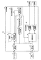
図1は、本発明の実施の形態1にかかるヒートポンプ給湯機100の制御装置110の構成図である。図2は、サーミスタ1の断面図であり、図3は、温度検出部3および温度変化量算出部4における動作を説明するための図であり、図4は、実施の形態1にかかるヒートポンプ給湯機100の動作を説明するためのフローチャートである。
FIG. 1 is a configuration diagram of a
図1には、ヒートポンプ給湯機100を構成する制御装置110と、例えば圧縮機14の冷媒吐出側における温度を計測し計測に係る信号1aを制御装置110へ出力するサーミスタ1と、圧縮機14の冷媒吐出側における圧力を計測し計測に係る信号3aを制御装置1へ出力する圧力センサ3と、圧縮機14および送風機15などが示されている。なお、図1には、説明を簡単化するため、ヒートポンプ給湯機100の負荷設備として圧縮機14および送風機15のみ示されているが制御装置110には例えば電磁弁なども接続されているものとする。
In FIG. 1, a
サーミスタ1は、図2に示されるように、計測対象(例えば圧縮機14の吐出配管の温度)の温度を測定するサーミスタ素子22、サーミスタ素子22を保護する充填樹脂23、これらを覆う銅ケース26、およびリード線25を有して構成され、サーミスタ内部の半田付け部24は、サーミスタ素子22とリード線25が半田付けにより接続される部分である。
As shown in FIG. 2, the
図1において、制御装置110は、主たる構成として、温度検出部2、圧力検出部9、温度変化量算出部4、温度補正部5、異常履歴記録部80、および駆動制御部85を有して構成されている。また、異常履歴記録部80は、異常発生回数出力部6、温度履歴データ生成部7、および記録部8を有して構成されており、駆動制御部85は、機器制御部10、圧縮機駆動部12、および送風機駆動部13を有して構成されている。
In FIG. 1, the
温度検出部2は、サーミスタ1からの信号1aを一定のサンプリング周期n毎にサンプリングして温度データ2aに変換する。図3に示される温度Tt0、Tt1、・・・Tta(aは1以上の整数)は、温度検出部2で生成されたサンプリング周期n毎の温度データ2aの一例である。圧力検出部9も同様に、圧力センサ3からの信号3aを一定のサンプリング周期n毎にサンプリングして圧力データ9aに変換する。
The temperature detector 2 samples the
温度変化量算出部4は、温度検出部2からの温度データ2aに基づいて、サンプリング周期nより長い周期である温度差検出周期N毎の温度変化量Δtを求める。温度変化量Δtは、例えば、所定の時刻t0に計測された温度Tt0と、所定時刻t0から温度差検出周期Nが経過したときの時刻taにおける温度Ttaとの差分値である。
Based on the
温度補正部5は、温度変化量算出部4から出力された負の温度変化量Δtの絶対値が所定値X[℃]以上であるか否かを判別し、所定値X以上のとき、負の温度変化量Δtの絶対値が所定値X未満の値となるように、温度変化量Δtが算出されたときの温度(例えば温度Tta)を下記(1)式に従って補正し、補正された温度Tta’を生成する。
Tta’[℃]=Tta[℃]−(Tta[℃]−Tt0[℃])・・・(1)
The
Tta ′ [° C.] = Tta [° C.] − (Tta [° C.] − Tt 0 [° C.]) (1)
所定値Xとしては、機器制御部10が圧縮機等の保護制御動作中にサーミスタ異常が発生した場合でもサーミスタ異常に起因する温度変化量Δtによって制御動作が停止されることを防止するため、例えば、保護制御動作中に想定される温度の上限値に設定される。 The predetermined value X is, for example, to prevent the control operation from being stopped due to the temperature change amount Δt caused by the thermistor abnormality even when the thermistor abnormality occurs during the protection control operation of the compressor or the like. The upper limit value of the temperature assumed during the protection control operation is set.
異常発生回数出力部6は、温度補正部5からの温度Tta’が検出される毎に、サーミスタ1における異常発生の回数を表す異常発生回数b1を1インクリメント(b1=b1+1)し、変更後の異常発生回数b1を温度履歴データ生成部7へ出力する。
Each time the abnormality occurrence number output unit 6 detects the temperature Tta ′ from the
温度履歴データ生成部7には、温度データ2a、温度Tta’、および異常発生回数b1が取り込まれる。温度履歴データ生成部7では、例えば温度Tta’が検出された時点における温度データ2aを時刻と対応付けた異常履歴データ7aが生成され、あるいは、温度Tta’が検出された時点における温度データ2aおよび異常発生回数b1を時刻と対応付けた異常履歴データ7aが生成される。生成された異常履歴データ7aは、記録部8に記録される。温度データ2aおよび異常発生回数b1を時刻と対応付けて記録することによって、サービス対応時において、異常履歴データ7aの信憑性の高低を直感的に把握することが可能となる。
The temperature history data generation unit 7 receives the
機器制御部10は、ヒートポンプ給湯機100の運転状態データ(例えば温度データ2aおよび圧力データ9a)に基づいて圧縮機等の駆動制御指令を生成して出力すると共に、ヒートポンプ給湯機100の運転異常が発生しているかどうかを判断して異常発生時には圧縮機等の運転を停止させる。
The
具体的に説明すると、機器制御部10で生成された駆動制御指令は、圧縮機駆動部12および送風機駆動部13などに入力され、圧縮機駆動部12および送風機駆動部13は、機器制御部10からの駆動制御指令に基づいて圧縮機14および送風機15を駆動させる。ここで、例えば温度データ2aが異常な値を示し、かつ、温度補正部5からの温度Tta’が検出された場合、機器制御部10では、サーミスタ異常と判断され駆動制御指令の生成が継続される。その結果、ヒートポンプ給湯機100の運転が継続される。
Specifically, the drive control command generated by the
一方、温度データ2aが異常な値を示し、かつ、温度Tta’が検出されない場合、機器制御部10ではサーミスタ異常以外の要因による温度異常と判断され、駆動制御指令の生成が停止される。その結果、ヒートポンプ給湯機100の運転が停止される。なお、機器制御部10の異常判定に用いられるデータは、温度データ2aおよび圧力データ9aに限定されるものではなく、例えば図示しない膨張弁の開度変化や運転開始からの経過時間などの運転状態データも考慮される。
On the other hand, when the
図4を用いて制御装置110の動作を説明する。制御装置110では、温度データ2aに基づいて温度差検出周期N毎の温度変化量Δtが求められる(ステップS1)。負の温度変化量Δtの絶対値が所定値X以上のとき(ステップS2,Yes)、この絶対値が所定値X未満の値となるように温度Ttaが補正され、補正された温度Tta’が生成される(ステップS3)。なお、この絶対値が所定値X未満の場合(ステップS2,No)、制御装置110では、ステップS1、S2の処理が繰り返される。
The operation of the
また、制御装置110では、温度Tta’が検出されたとき、異常発生回数b1が1インクリメントされる(ステップS4)。変更後の異常発生回数b1は、温度Tta’が生成された時点における温度データ2aおよび時刻と対応付けられて異常履歴データ7aが生成される(ステップS5)。そして生成された異常履歴データ7aは、記録部8に記録される(ステップS6)。
Further, in the
また、制御装置110では、温度Tta’が検出されたとき(ステップS7,Yes)、ヒートポンプ給湯機100の運転が継続され(ステップS8)、運転異常が検出され、かつ、温度Tta’が検出されないとき(ステップS7,No)、ヒートポンプ給湯機100の運転が停止される(ステップS9)。
Further, in the
以上のように、実施の形態1にかかるヒートポンプ給湯機100は、温度センサ(サーミスタ1)で計測された温度信号(信号1a)を一定周期でサンプリングした温度データ2aに基づいて、一定周期(サンプリング周期n)より長い周期(温度差検出周期N)で単位時間当たりの温度変化量Δtを算出する温度変化量算出部4と、温度変化量算出部4から出力された負の温度変化量Δtの絶対値が所定値X以上のとき、この絶対値が所定値X未満の値となるように温度変化量Δtが算出された時点における第一の温度(温度Tta)を補正し、補正された第二の温度(温度Tta’)を生成して出力する温度補正部5と、温度補正部5からの第二の温度Tta’を検出する毎に、サーミスタ1の異常発生回数を増加させるように変更し、第二の温度Tta’が検出された時点における温度データ2aと変更された異常発生回数b1とを対応付けた異常履歴を記録する異常履歴記録部80と、温度データ2aを含む運転状態データに基づいて圧縮機14を含む機器群の駆動を制御(停止あるいは継続)すると共に、温度補正部5からの第二の温度Tta’を検出しているときには機器群の駆動を継続させる駆動制御部85と、を備えるようにしたので、サーミスタ1で計測された低下傾向にある温度変化量Δtの絶対値が所定値X以上のときのサーミスタ異常の履歴が記録され、かつ、ヒートポンプ給湯機100の運転制御が継続される。従って、機器制御部10が圧縮機等の保護制御動作中にサーミスタ異常が発生した場合でも、圧縮機等の保護制御動作などが停止されることがなく、サービス対応時の効率化を図ることが可能である。
As described above, the heat
実施の形態2.
図5は、本発明の実施の形態2にかかるヒートポンプ給湯機200の制御装置210の構成図であり、図6は、実施の形態2にかかるヒートポンプ給湯機200の動作を説明するためのフローチャートである。以下、実施の形態1と同一部分には同一符号を付してその説明を省略し、ここでは異なる部分についてのみ述べる。
Embodiment 2. FIG.
FIG. 5 is a configuration diagram of the
図5に示される制御装置210は、主たる構成として、温度検出部2、圧力検出部9、温度変化量算出部4、温度補正部50、異常履歴記録部81、比較部90、および駆動制御部86を有して構成されている。また、異常履歴記録部81は、第一の異常発生回数出力部61、第二の異常発生回数出力部62、温度履歴データ生成部70、および記録部8を有して構成されており、駆動制御部86は、機器制御部11、圧縮機駆動部12、および送風機駆動部13を有して構成されている。
A
実施の形態1の制御装置110との相違点は、温度補正部5、異常発生回数出力部6、温度履歴データ生成部70、および機器制御部10の代わりに、温度補正部50、第一の異常発生回数出力部61、温度履歴データ生成部70、機器制御部11が設けられ、温度補正部50と機器制御部11との間に第二の異常発生回数出力部62が設けられ、第一の異常発生回数出力部61と機器制御部11との間に比較部90が設けられている点である。
The difference from the
温度補正部50では、温度変化量算出部4から出力された負の温度変化量Δtの絶対値が所定値X以上であるか否かが判断されると共に、この所定値X以上の温度変化量Δtの絶対値が、所定値Xより大きい所定値Y[℃]以上であるか否かが判定される。また、温度補正部50は、負の温度変化量Δtの絶対値が所定値X以上、かつ、所定値Y未満のとき、この絶対値が所定値X未満の値となるように、この温度変化量Δtが算出されたときの温度(例えば温度Tta)を、上記(1)式に従って補正し、補正された温度Tta’を生成する。
The
また、温度補正部50は、負の温度変化量Δtの絶対値が所定値X以上、かつ、所定値Y以上のとき、この温度変化量Δtが算出されたときの温度Ttaを補正することなく第二の異常発生回数出力部62へ出力する。
Further, the
所定値Yとしては、上述した二次的な機器異常を抑制するため、例えば過負荷運転時に想定される温度の下限値が設定される。所定値Yをこのような値に設定することによって、負の温度変化量Δtの絶対値が所定値Yを超えた時、温度補正部50からの温度Ttaが機器制御部11に取り込まれ、ヒートポンプ給湯機200の過負荷運転が抑制される。
As the predetermined value Y, for example, a lower limit value of a temperature assumed during overload operation is set in order to suppress the secondary device abnormality described above. By setting the predetermined value Y to such a value, when the absolute value of the negative temperature change amount Δt exceeds the predetermined value Y, the temperature Tta from the
第一の異常発生回数出力部61は、温度補正部50からの温度Tta’が検出される毎に、サーミスタ1で異常が発生したことを表す異常発生回数b1を1インクリメント(b1=b1+1)し、変更後の異常発生回数b1を温度履歴データ生成部70へ出力する。
The first abnormality occurrence
比較部90は、第一の異常発生回数出力部61からの異常発生回数b1と予め設定された所定回数Zとの比較が行われ、異常発生回数b1が所定回数Zを未満の場合には、温度補正部50からの温度Tta’を機器制御部11へ出力し、異常発生回数b1が所定回数Zを超えている場合には、例えば第二の異常発生回数出力部62に入力される温度Ttaと同等の値の温度Tta”を出力する。
The
具体的に説明する。補正された温度Tta’の生成回数(すなわち異常発生回数b1)が比較的多い場合、サーミスタ1が正確な温度を計測することができない程度まで半田クラックが進行している可能性が高く、このような状態でヒートポンプ給湯機200の運転が継続された場合には、負の温度変化量Δtの絶対値が所定値Yを超えていなくとも過負荷運転による二次的な機器異常が引き起こされる可能性がある。そこで、比較部90は、異常発生回数b1が所定回数Z以下の場合には機器制御部11へ温度Tta’を出力するが、異常発生回数b1が所定回数Zを超える場合には、過負荷運転を予備的に防止するため、温度Ttaと同等の値の温度Tta”を出力するように構成されている。
This will be specifically described. When the corrected number of generations of the temperature Tta ′ (that is, the number of occurrences of abnormality b1) is relatively large, it is highly likely that the solder crack has progressed to such an extent that the
第二の異常発生回数出力部62は、温度補正部50からの温度Ttaが検出されたとき、異常発生回数b2を1インクリメント(b2=b2+1)すると共に、温度Ttaを機器制御部11へ出力する。
When the temperature Tta from the
温度履歴データ生成部70では、温度検出部2からの温度データ2a、温度補正部50からの温度Tta’、第一の異常発生回数出力部61からの異常発生回数b1、および第二の異常発生回数出力部62からの異常発生回数b2が取り込まれる。温度履歴データ生成部70では、温度Tta’が取り込まれた時点における温度データ2aを時刻と対応付けた異常履歴データ7aが生成され、あるいは、温度履歴データ生成部70では、温度Tta’が取り込まれた時点における温度データ2a、異常発生回数b1、および異常発生回数b2を時刻と対応付けた異常履歴データ7aが生成される。生成された異常履歴データ7aは、記録部8に記録される。
In the temperature history
温度データ2aおよび異常発生回数b1(または異常発生回数b2)を時刻と対応付けて記録することによって、サービス対応時において、異常履歴データ7aの信憑性の高低を直感的に把握することが可能となる。また、温度データ2a、異常発生回数b1、および異常発生回数b2を時刻と対応付けて記録することによって、サービス対応時におけるサーミスタ異常履歴データ7aの信憑性をより高めることが可能となる。
By recording the
機器制御部11は、ヒートポンプ給湯機200の運転状態データ(例えば温度データ2aおよび圧力データ9a)に基づいて圧縮機等の駆動制御指令を生成して出力すると共に、ヒートポンプ給湯機200の運転異常が発生しているかどうかを判断して異常発生時には圧縮機等の運転を停止させる。
The
具体的に説明すると、機器制御部11で生成された駆動制御指令は、圧縮機駆動部12および送風機駆動部13などに入力され、圧縮機駆動部12および送風機駆動部13は、機器制御部11からの駆動制御指令に基づいて圧縮機14および送風機15を駆動させる。ここで、例えば温度データ2aが異常な値を示し、かつ、温度補正部50からの温度Tta’が検出された場合、機器制御部11では、実施の形態1と同様に、ヒートポンプ給湯機200の運転異常ではなくサーミスタ異常と判断され、駆動制御指令の生成が継続される。その結果、ヒートポンプ給湯機200の運転が継続される。
Specifically, the drive control command generated by the
また、温度データ2aが異常な値を示し、かつ、温度Tta’が検出されない場合(すなわち温度Ttaまたは温度Tta”が検出された場合)、機器制御部11では、過負荷運転を防止するため駆動制御指令の生成が停止される。その結果、ヒートポンプ給湯機200の運転が停止される。
When the
図6を用いて制御装置210の動作を説明する。温度変化量算出部4では、温度データ2aに基づいて温度差検出周期N毎の温度変化量Δtが求められ(ステップS21)、負の温度変化量Δtの絶対値が所定値X以上のとき(ステップS22,Yes)、この絶対値が所定値Y以上であるか否かが判断される。なお、負の温度変化量Δtの絶対値が所定値X未満の場合(ステップS22,No)、ステップS21、S22の処理が繰り返される。
The operation of the
負の温度変化量Δtの絶対値が所定値Y以上のとき(ステップS23,Yes)、異常発生回数b2が1インクリメントされ(ステップS24)、かつ、ヒートポンプ給湯機200の運転が停止される(ステップS25)。
When the absolute value of the negative temperature change Δt is greater than or equal to the predetermined value Y (step S23, Yes), the abnormality occurrence count b2 is incremented by 1 (step S24), and the operation of the heat
一方、負の温度変化量Δtの絶対値が所定値Y未満のとき(ステップS23,No)、この絶対値が所定値X未満の値となるように温度Ttaが補正され、補正された温度Tta’が生成される(ステップS26)。温度Tta’が生成されたとき異常発生回数b1が1インクリメントされ(ステップS27)、異常履歴データ7aが生成される(ステップS28)。そして生成された異常履歴データ7aは、記録部8に記録される(ステップS29)。
On the other hand, when the absolute value of the negative temperature change amount Δt is less than the predetermined value Y (step S23, No), the temperature Tta is corrected so that the absolute value becomes a value less than the predetermined value X, and the corrected temperature Tta 'Is generated (step S26). When the temperature Tta 'is generated, the abnormality occurrence count b1 is incremented by 1 (step S27), and
異常発生回数b1が所定回数Zを超えたとき(ステップS30,Yes)、ヒートポンプ給湯機200の運転が停止され(ステップS25)、異常発生回数b1が所定回数Z以下のとき(ステップS30,No)、ヒートポンプ給湯機200の運転が継続される(ステップS31)。
When the abnormality occurrence number b1 exceeds the predetermined number Z (step S30, Yes), the operation of the heat
なお、実施の形態2の駆動制御部86は、温度補正部50からの温度Ttaが第二の異常発生回数出力部62を介して機器制御部11に取り込まれるように構成されているが、温度補正部50からの温度Ttaが第二の異常発生回数出力部62を返さずに機器制御部11へ取り込まれるように構成してもよい。このように構成した場合、記録部8には温度Ttaに関する異常履歴データ7aが記録されないが、過負荷運転を防止するためにヒートポンプ給湯機200の運転を停止させることは可能である。
The
以上に説明したように、実施の形態2にかかる制御装置210の温度補正部50は、所定値Xを第一の所定値として、前記絶対値がこの第一の所定値X以上、かつ、第一の所定値Xより大きい第二の所定値Y未満のときには第二の温度Tta’を生成して出力し、前記絶対値が第二の所定値Y以上のときには第一の温度Ttaを出力し、異常履歴記録部81は、温度補正部50からの第二の温度Tta’を検出する毎に、サーミスタ1の異常発生回数を増加させるように変更して出力する第一の異常発生回数出力部61と、温度補正部50からの第一の温度Ttaを検出する毎に、サーミスタ1の異常発生回数を増加させるように変更して出力する第二の異常発生回数出力部62と、第一の異常発生回数出力部61からの変更された異常発生回数b1と第二の温度Tta’が検出された時点における前記温度データ2aとを対応付けた異常履歴データ7a、または、第二の異常発生回数出力部62からの変更された異常発生回数b2と第一の温度Ttaが検出された時点における温度データ2aとを対応付けた異常履歴データ7aを生成して、記録部8に記録させる温度履歴データ生成部70と、を有するようにしたので、実施の形態1の効果に加えて、記録部8に記録される異常履歴データ7aの信憑性をより高めることができ、サービス対応時の効率化をより高めることが可能である。
As described above, the
また、実施の形態2にかかる駆動制御部86は、温度補正部50からの第一の温度Ttaを検出したとき機器群の駆動を停止させるようにしたので、ヒートポンプ給湯機200の過負荷運転を抑制することが可能である。
Moreover, since the
実施の形態2にかかる制御装置210は、第一の異常発生回数出力部61からの異常発生回数b1が所定回数Zを超えているとき第一の温度Ttaと同等の温度Tta”を出力する温度出力部(比較部90)を備え、駆動制御部86は、比較部90からの温度Tta”を検出したとき機器群の駆動を停止させることようにしたので、ヒートポンプ給湯機200の過負荷運転を予備的に防止することが可能である。
The
また、実施の形態2にかかる温度補正部50は、ヒートポンプ給湯機200の保護制御動作中に想定される温度変化の最大値を第一の所定値(所定値X)として設定し、サーミスタ1の異常に起因したヒートポンプ給湯機200の過負荷運転時に想定される温度変化の最小値を第二の所定値(所定値Y)として設定するようにしたので、実施の形態1の効果に加えて、圧縮機等の保護制御動作がサーミスタ異常に起因して停止されることを防止し、かつ、過負荷運転による二次的な機器異常を防止することができる。
Further, the
なお、本発明の実施の形態1、2にかかるヒートポンプ給湯機の制御装置は、本発明の内容の一例を示すものであり、更なる別の公知の技術と組み合わせることも可能であるし、本発明の要旨を逸脱しない範囲で、一部を省略するなど、変更して構成することも可能であることは無論である。
In addition, the control apparatus of the heat pump water
以上のように、本発明は、ヒートポンプ給湯機の制御装置に適用可能であり、特に、サーミスタ異常に起因した二次的な機器異常が引き起こされる可能性を抑制し、かつ、サービス対応の効率化を図ることが可能な発明として有用である。 As described above, the present invention is applicable to a control device for a heat pump water heater, and in particular, suppresses the possibility of causing a secondary device abnormality due to a thermistor abnormality, and improves service response efficiency. This is useful as an invention capable of achieving the above.
1 サーミスタ(温度センサ)
1a、3a 信号
2 温度検出部
2a 温度データ
3 圧力センサ
4 温度変化量算出部
5、50 温度補正部
6 異常発生回数出力部
7、70 温度履歴データ生成部
7a 異常履歴データ
9 圧力検出部
9a 圧力データ
10、11 機器制御部
12 圧縮機駆動部
13 送風機駆動部
14 圧縮機
15 送風機
22 サーミスタ素子
23 充填樹脂
24 半田付け部
25 リード線
61 第一の異常発生回数出力部
62 第二の異常発生回数出力部
80、81 異常履歴記録部
85、86 駆動制御部
90 比較部(温度出力部)
100、200 ヒートポンプ給湯機
110、210 制御装置
b1、b2 異常発生回数
Tta 温度(第一の温度)
Tta’ 温度(第二の温度)
X 所定値(第一の所定値)
Y 所定値(第二の所定値)
Z 所定回数
1 Thermistor (temperature sensor)
DESCRIPTION OF
100, 200 Heat
Tta 'temperature (second temperature)
X predetermined value (first predetermined value)
Y predetermined value (second predetermined value)
Z Predetermined number of times
Claims (4)
前記温度変化量算出部から出力された負の温度変化量の絶対値が所定値以上のとき、この絶対値が前記所定値未満の値となるように前記温度変化量が算出された時点における第一の温度を、前記温度変化量が算出された時点から前記温度差検出周期分前の時点に計測された温度に変更し、変更後の温度を第二の温度として出力する温度補正部と、
前記温度補正部からの第二の温度を検出する毎に、前記温度センサの異常発生回数を増加させるように変更し、前記第二の温度が検出された時点における前記温度データと変更された異常発生回数とを対応付けた異常履歴を記録する異常履歴記録部と、
前記温度補正部からの第二の温度を検出しているときには圧縮機を含む機器群の駆動を継続させる駆動制御部と、
を備えたことを特徴とするヒートポンプ給湯機の制御装置。 A temperature change amount calculation unit that calculates a temperature change amount per unit time in a temperature difference detection cycle longer than the fixed cycle based on temperature data obtained by sampling the temperature signal measured by the temperature sensor at a fixed cycle;
When the absolute value of the negative temperature change amount output from the temperature change amount calculation unit is greater than or equal to a predetermined value, the first time point when the temperature change amount is calculated so that the absolute value is less than the predetermined value. A temperature correction unit that changes one temperature to a temperature measured at a time point before the temperature difference detection period from a time point when the temperature change amount is calculated, and outputs the changed temperature as a second temperature;
Each time the second temperature from the temperature correction unit is detected, the temperature sensor is changed to increase the number of occurrences of the abnormality, and the temperature data and the abnormality changed when the second temperature is detected. An anomaly history recording unit for recording an anomaly history associated with the number of occurrences;
A drive control unit that continues to drive the device group including the compressor when the second temperature from the temperature correction unit is detected;
The control apparatus of the heat pump water heater characterized by the above-mentioned.
前記所定値を第一の所定値として、前記絶対値がこの第一の所定値以上、かつ、前記第一の所定値より大きい第二の所定値未満のときには前記第二の温度を生成して出力し、前記絶対値が第二の所定値以上のときには前記第一の温度を出力し、
前記異常履歴記録部は、
前記温度補正部からの第二の温度を検出する毎に、前記温度センサの異常発生回数を増加させるように変更して出力する第一の異常発生回数出力部と、
前記温度補正部からの第一の温度を検出する毎に、前記温度センサの異常発生回数を増加させるように変更して出力する第二の異常発生回数出力部と、
前記第一の異常発生回数出力部からの変更された異常発生回数と前記第二の温度が検出された時点における前記温度データとを対応付けた異常履歴データ、または、前記第二の異常発生回数出力部からの変更された異常発生回数と前記第一の温度が検出された時点における前記温度データとを対応付けた異常履歴データを生成して、記録部に記録させる温度履歴データ生成部と、
を有することを特徴とする請求項1に記載のヒートポンプ給湯機の制御装置。 The temperature correction unit is
When the predetermined value is a first predetermined value, the second temperature is generated when the absolute value is greater than or equal to the first predetermined value and less than a second predetermined value greater than the first predetermined value. Output the first temperature when the absolute value is greater than or equal to a second predetermined value,
The abnormality history recording unit
Each time the second temperature from the temperature correction unit is detected, a first abnormality occurrence number output unit that changes and outputs to increase the number of abnormality occurrences of the temperature sensor;
Each time the first temperature from the temperature correction unit is detected, a second abnormality occurrence number output unit that changes and outputs the abnormality occurrence number of the temperature sensor, and
The abnormality history data in which the changed abnormality occurrence number from the first abnormality occurrence number output unit is associated with the temperature data at the time when the second temperature is detected, or the second abnormality occurrence number A temperature history data generation unit that generates abnormality history data that associates the changed number of occurrences of abnormality from the output unit and the temperature data at the time when the first temperature is detected, and causes the recording unit to record the abnormality history data;
The control device for a heat pump water heater according to claim 1, wherein:
前記駆動制御部は、この温度出力部からの温度を検出したとき前記機器群の駆動を停止させることを特徴とする請求項1〜3の何れか1つに記載のヒートポンプ給湯機の制御装置。 A temperature output unit that outputs a temperature equivalent to the first temperature when the number of times of abnormality occurrence from the first abnormality occurrence number output unit exceeds a predetermined number of times,
The said drive control part stops the drive of the said apparatus group, when the temperature from this temperature output part is detected, The control apparatus of the heat pump water heater as described in any one of Claims 1-3 characterized by the above-mentioned.
Priority Applications (1)
| Application Number | Priority Date | Filing Date | Title |
|---|---|---|---|
| JP2012054986A JP5901366B2 (en) | 2012-03-12 | 2012-03-12 | Control device for heat pump water heater |
Applications Claiming Priority (1)
| Application Number | Priority Date | Filing Date | Title |
|---|---|---|---|
| JP2012054986A JP5901366B2 (en) | 2012-03-12 | 2012-03-12 | Control device for heat pump water heater |
Publications (2)
| Publication Number | Publication Date |
|---|---|
| JP2013190117A JP2013190117A (en) | 2013-09-26 |
| JP5901366B2 true JP5901366B2 (en) | 2016-04-06 |
Family
ID=49390571
Family Applications (1)
| Application Number | Title | Priority Date | Filing Date |
|---|---|---|---|
| JP2012054986A Active JP5901366B2 (en) | 2012-03-12 | 2012-03-12 | Control device for heat pump water heater |
Country Status (1)
| Country | Link |
|---|---|
| JP (1) | JP5901366B2 (en) |
Families Citing this family (1)
| Publication number | Priority date | Publication date | Assignee | Title |
|---|---|---|---|---|
| CN105605791B (en) * | 2016-01-22 | 2019-03-08 | 广州松下空调器有限公司 | The control method of water heater elimination run |
Family Cites Families (5)
| Publication number | Priority date | Publication date | Assignee | Title |
|---|---|---|---|---|
| JPH01302373A (en) * | 1988-05-31 | 1989-12-06 | Citizen Watch Co Ltd | Temperature control system |
| JP3431377B2 (en) * | 1995-12-01 | 2003-07-28 | 株式会社日立製作所 | Air conditioner |
| JP4730578B2 (en) * | 2001-09-28 | 2011-07-20 | 株式会社ノーリツ | Hot water storage water heater |
| JP3841045B2 (en) * | 2002-11-18 | 2006-11-01 | 株式会社ノーリツ | Combustion device |
| JP2011007416A (en) * | 2009-06-25 | 2011-01-13 | Mitsubishi Electric Corp | Control device, method of controlling water heater and the water heater |
-
2012
- 2012-03-12 JP JP2012054986A patent/JP5901366B2/en active Active
Also Published As
| Publication number | Publication date |
|---|---|
| JP2013190117A (en) | 2013-09-26 |
Similar Documents
| Publication | Publication Date | Title |
|---|---|---|
| KR101137740B1 (en) | System and method for calibrating parameters for a refrigeration system with a variable speed compressor | |
| WO2018228135A1 (en) | Control method and system for preventing compressor overheating of variable-frequency air conditioner | |
| KR101492590B1 (en) | System and method for monitoring overheat of compressor | |
| KR101182759B1 (en) | System and method for evaluating parameters for a refrigeration system with a variable speed compressor | |
| JP6686134B2 (en) | Integrated device and method for enhancing heater life and performance | |
| US20100177451A1 (en) | Motor Overload Protecting Method | |
| CN108050663A (en) | Control method and device, air-conditioning and the storage medium of compressor self-shield | |
| JP6940520B2 (en) | How to protect the motor of a device with a motor driven consumer with a continuous capacity control system and the choice of that motor | |
| JP2008202905A (en) | Air conditioner | |
| JP6959660B2 (en) | Cooling system control and protection device | |
| JP5901366B2 (en) | Control device for heat pump water heater | |
| WO2014191051A1 (en) | Detecting surge in a compression system | |
| WO2020035993A1 (en) | Control device, refrigerator, control method, and abnormality detection method | |
| JP4840108B2 (en) | Compressor protection control method for air conditioner | |
| JP6786009B2 (en) | Air conditioner | |
| JP5258627B2 (en) | Air conditioner | |
| JP6126896B2 (en) | Air conditioner | |
| JP5501987B2 (en) | Air conditioner | |
| JP2011158121A (en) | Air conditioner | |
| JP4857866B2 (en) | Refrigeration equipment | |
| KR20120068686A (en) | Diagnosis of stator thermal anomalies in an electrical machine | |
| JP2011179762A (en) | Heat pump hot water generator | |
| JP2016065679A (en) | Device and method for detecting abnormality for power transmission belt of air conditioner | |
| JP6116778B1 (en) | Motor control device | |
| JP7120893B2 (en) | Gas turbine and its extraction amount adjustment method |
Legal Events
| Date | Code | Title | Description |
|---|---|---|---|
| A621 | Written request for application examination |
Free format text: JAPANESE INTERMEDIATE CODE: A621 Effective date: 20140529 |
|
| A977 | Report on retrieval |
Free format text: JAPANESE INTERMEDIATE CODE: A971007 Effective date: 20150128 |
|
| A131 | Notification of reasons for refusal |
Free format text: JAPANESE INTERMEDIATE CODE: A131 Effective date: 20150210 |
|
| A521 | Written amendment |
Free format text: JAPANESE INTERMEDIATE CODE: A523 Effective date: 20150402 |
|
| A131 | Notification of reasons for refusal |
Free format text: JAPANESE INTERMEDIATE CODE: A131 Effective date: 20150901 |
|
| A521 | Written amendment |
Free format text: JAPANESE INTERMEDIATE CODE: A523 Effective date: 20150928 |
|
| TRDD | Decision of grant or rejection written | ||
| A01 | Written decision to grant a patent or to grant a registration (utility model) |
Free format text: JAPANESE INTERMEDIATE CODE: A01 Effective date: 20160209 |
|
| A61 | First payment of annual fees (during grant procedure) |
Free format text: JAPANESE INTERMEDIATE CODE: A61 Effective date: 20160308 |
|
| R150 | Certificate of patent or registration of utility model |
Ref document number: 5901366 Country of ref document: JP Free format text: JAPANESE INTERMEDIATE CODE: R150 |
|
| R250 | Receipt of annual fees |
Free format text: JAPANESE INTERMEDIATE CODE: R250 |
|
| R250 | Receipt of annual fees |
Free format text: JAPANESE INTERMEDIATE CODE: R250 |
|
| R250 | Receipt of annual fees |
Free format text: JAPANESE INTERMEDIATE CODE: R250 |
|
| R250 | Receipt of annual fees |
Free format text: JAPANESE INTERMEDIATE CODE: R250 |
|
| R250 | Receipt of annual fees |
Free format text: JAPANESE INTERMEDIATE CODE: R250 |