JP5894979B2 - Distance estimation using speech signals - Google Patents
Distance estimation using speech signals Download PDFInfo
- Publication number
- JP5894979B2 JP5894979B2 JP2013510706A JP2013510706A JP5894979B2 JP 5894979 B2 JP5894979 B2 JP 5894979B2 JP 2013510706 A JP2013510706 A JP 2013510706A JP 2013510706 A JP2013510706 A JP 2013510706A JP 5894979 B2 JP5894979 B2 JP 5894979B2
- Authority
- JP
- Japan
- Prior art keywords
- distance
- signal
- audio
- band
- sound
- Prior art date
- Legal status (The legal status is an assumption and is not a legal conclusion. Google has not performed a legal analysis and makes no representation as to the accuracy of the status listed.)
- Active
Links
- 238000012360 testing method Methods 0.000 claims description 73
- 230000004044 response Effects 0.000 claims description 30
- 238000009826 distribution Methods 0.000 claims description 6
- 238000005259 measurement Methods 0.000 description 46
- 238000002604 ultrasonography Methods 0.000 description 41
- 230000005236 sound signal Effects 0.000 description 30
- 238000013459 approach Methods 0.000 description 27
- 238000000034 method Methods 0.000 description 20
- 230000000875 corresponding effect Effects 0.000 description 19
- 230000008859 change Effects 0.000 description 11
- 230000006870 function Effects 0.000 description 11
- 230000009021 linear effect Effects 0.000 description 10
- 230000005855 radiation Effects 0.000 description 9
- 230000000694 effects Effects 0.000 description 8
- 230000001965 increasing effect Effects 0.000 description 8
- 230000008569 process Effects 0.000 description 8
- 238000005457 optimization Methods 0.000 description 5
- 230000008447 perception Effects 0.000 description 5
- 230000006978 adaptation Effects 0.000 description 4
- 238000003491 array Methods 0.000 description 4
- 230000005540 biological transmission Effects 0.000 description 4
- 238000009877 rendering Methods 0.000 description 4
- 230000008878 coupling Effects 0.000 description 3
- 238000010168 coupling process Methods 0.000 description 3
- 238000005859 coupling reaction Methods 0.000 description 3
- 230000003111 delayed effect Effects 0.000 description 3
- 238000001514 detection method Methods 0.000 description 3
- 230000002829 reductive effect Effects 0.000 description 3
- 230000004888 barrier function Effects 0.000 description 2
- 230000009286 beneficial effect Effects 0.000 description 2
- 230000002596 correlated effect Effects 0.000 description 2
- 230000001419 dependent effect Effects 0.000 description 2
- 238000013461 design Methods 0.000 description 2
- 239000006185 dispersion Substances 0.000 description 2
- 238000004519 manufacturing process Methods 0.000 description 2
- 230000007246 mechanism Effects 0.000 description 2
- 230000009022 nonlinear effect Effects 0.000 description 2
- 238000007781 pre-processing Methods 0.000 description 2
- 238000012545 processing Methods 0.000 description 2
- 230000003595 spectral effect Effects 0.000 description 2
- 230000002159 abnormal effect Effects 0.000 description 1
- 238000007792 addition Methods 0.000 description 1
- 230000002238 attenuated effect Effects 0.000 description 1
- 230000008901 benefit Effects 0.000 description 1
- 230000015572 biosynthetic process Effects 0.000 description 1
- 238000004364 calculation method Methods 0.000 description 1
- 238000010276 construction Methods 0.000 description 1
- 230000001276 controlling effect Effects 0.000 description 1
- 230000007423 decrease Effects 0.000 description 1
- 230000003247 decreasing effect Effects 0.000 description 1
- 238000011156 evaluation Methods 0.000 description 1
- 238000000605 extraction Methods 0.000 description 1
- 238000001914 filtration Methods 0.000 description 1
- 238000010304 firing Methods 0.000 description 1
- 230000001939 inductive effect Effects 0.000 description 1
- 230000003993 interaction Effects 0.000 description 1
- 230000001788 irregular Effects 0.000 description 1
- 230000000670 limiting effect Effects 0.000 description 1
- 238000013178 mathematical model Methods 0.000 description 1
- 230000008520 organization Effects 0.000 description 1
- 239000000047 product Substances 0.000 description 1
- 230000009467 reduction Effects 0.000 description 1
- 238000005070 sampling Methods 0.000 description 1
- 230000003068 static effect Effects 0.000 description 1
- 239000013589 supplement Substances 0.000 description 1
- 230000036962 time dependent Effects 0.000 description 1
Images


Classifications
-
- G—PHYSICS
- G01—MEASURING; TESTING
- G01S—RADIO DIRECTION-FINDING; RADIO NAVIGATION; DETERMINING DISTANCE OR VELOCITY BY USE OF RADIO WAVES; LOCATING OR PRESENCE-DETECTING BY USE OF THE REFLECTION OR RERADIATION OF RADIO WAVES; ANALOGOUS ARRANGEMENTS USING OTHER WAVES
- G01S15/00—Systems using the reflection or reradiation of acoustic waves, e.g. sonar systems
- G01S15/02—Systems using the reflection or reradiation of acoustic waves, e.g. sonar systems using reflection of acoustic waves
- G01S15/06—Systems determining the position data of a target
- G01S15/08—Systems for measuring distance only
- G01S15/32—Systems for measuring distance only using transmission of continuous waves, whether amplitude-, frequency-, or phase-modulated, or unmodulated
-
- G—PHYSICS
- G01—MEASURING; TESTING
- G01S—RADIO DIRECTION-FINDING; RADIO NAVIGATION; DETERMINING DISTANCE OR VELOCITY BY USE OF RADIO WAVES; LOCATING OR PRESENCE-DETECTING BY USE OF THE REFLECTION OR RERADIATION OF RADIO WAVES; ANALOGOUS ARRANGEMENTS USING OTHER WAVES
- G01S15/00—Systems using the reflection or reradiation of acoustic waves, e.g. sonar systems
- G01S15/88—Sonar systems specially adapted for specific applications
- G01S15/89—Sonar systems specially adapted for specific applications for mapping or imaging
-
- G—PHYSICS
- G01—MEASURING; TESTING
- G01S—RADIO DIRECTION-FINDING; RADIO NAVIGATION; DETERMINING DISTANCE OR VELOCITY BY USE OF RADIO WAVES; LOCATING OR PRESENCE-DETECTING BY USE OF THE REFLECTION OR RERADIATION OF RADIO WAVES; ANALOGOUS ARRANGEMENTS USING OTHER WAVES
- G01S7/00—Details of systems according to groups G01S13/00, G01S15/00, G01S17/00
- G01S7/52—Details of systems according to groups G01S13/00, G01S15/00, G01S17/00 of systems according to group G01S15/00
- G01S7/534—Details of non-pulse systems
-
- H—ELECTRICITY
- H04—ELECTRIC COMMUNICATION TECHNIQUE
- H04R—LOUDSPEAKERS, MICROPHONES, GRAMOPHONE PICK-UPS OR LIKE ACOUSTIC ELECTROMECHANICAL TRANSDUCERS; DEAF-AID SETS; PUBLIC ADDRESS SYSTEMS
- H04R3/00—Circuits for transducers, loudspeakers or microphones
- H04R3/12—Circuits for transducers, loudspeakers or microphones for distributing signals to two or more loudspeakers
-
- H—ELECTRICITY
- H04—ELECTRIC COMMUNICATION TECHNIQUE
- H04S—STEREOPHONIC SYSTEMS
- H04S7/00—Indicating arrangements; Control arrangements, e.g. balance control
- H04S7/30—Control circuits for electronic adaptation of the sound field
- H04S7/301—Automatic calibration of stereophonic sound system, e.g. with test microphone
-
- G—PHYSICS
- G01—MEASURING; TESTING
- G01S—RADIO DIRECTION-FINDING; RADIO NAVIGATION; DETERMINING DISTANCE OR VELOCITY BY USE OF RADIO WAVES; LOCATING OR PRESENCE-DETECTING BY USE OF THE REFLECTION OR RERADIATION OF RADIO WAVES; ANALOGOUS ARRANGEMENTS USING OTHER WAVES
- G01S7/00—Details of systems according to groups G01S13/00, G01S15/00, G01S17/00
- G01S7/52—Details of systems according to groups G01S13/00, G01S15/00, G01S17/00 of systems according to group G01S15/00
- G01S7/523—Details of pulse systems
- G01S7/524—Transmitters
-
- H—ELECTRICITY
- H04—ELECTRIC COMMUNICATION TECHNIQUE
- H04R—LOUDSPEAKERS, MICROPHONES, GRAMOPHONE PICK-UPS OR LIKE ACOUSTIC ELECTROMECHANICAL TRANSDUCERS; DEAF-AID SETS; PUBLIC ADDRESS SYSTEMS
- H04R2203/00—Details of circuits for transducers, loudspeakers or microphones covered by H04R3/00 but not provided for in any of its subgroups
- H04R2203/12—Beamforming aspects for stereophonic sound reproduction with loudspeaker arrays
-
- H—ELECTRICITY
- H04—ELECTRIC COMMUNICATION TECHNIQUE
- H04R—LOUDSPEAKERS, MICROPHONES, GRAMOPHONE PICK-UPS OR LIKE ACOUSTIC ELECTROMECHANICAL TRANSDUCERS; DEAF-AID SETS; PUBLIC ADDRESS SYSTEMS
- H04R2217/00—Details of magnetostrictive, piezoelectric, or electrostrictive transducers covered by H04R15/00 or H04R17/00 but not provided for in any of their subgroups
- H04R2217/03—Parametric transducers where sound is generated or captured by the acoustic demodulation of amplitude modulated ultrasonic waves
Description
本発明は、対象物までの距離の推定に関し、排他的ではないが特に、距離の推定に基づく音声環境の特徴づけに関する。 The present invention relates to estimation of distance to an object, and more particularly, but not exclusively, to characterizing a speech environment based on distance estimation.
距離の自動化された決定は、多くのアプリケーションにとって重要である。例えば、音声環境はラウドスピーカーシステムのパフォーマンスに非常に影響を及ぼし、例えば、部屋の音響効果は、空間音声再生システムにより供給される空間経験に著しく影響を及ぼす。従って、最高の空間レンダリングを提供するために、音声再生システムが特定の音声環境に適切に調整されることは重要である。部屋サイズ、音響システム位置及びリスナー位置等の各ありうる置き換えを前もって考慮することは可能ではないので、限定された数の予め設定されたオプションを提供することだけが実際に可能である。従って、音声再生システムの適当な較正は、元の位置での器材で実施されなければならない。音声再生を最適化するために、部屋ジオメトリ(配置及び/又は形状)リスニング位置及びレンダリング装置の配置は、好ましくは既知であるべきである。手動でこのデータを測定することが可能である一方、これはユーザ側の望ましくない量の労力を示し、ユーザエラーになりやすい。部屋ジオメトリが自動的に測定できる場合、最適化は自動であり、ユーザエラーがなくなり得る。斯様な部屋ジオメトリは壁のような部屋対象物までの距離測定から決定され、従って、対象物までの距離を決定するための実用的なシステムが非常に有利である。 Automated determination of distance is important for many applications. For example, the audio environment can greatly affect the performance of a loudspeaker system, for example, room acoustics can significantly affect the spatial experience provided by a spatial audio reproduction system. Therefore, it is important that the audio playback system is properly tuned to a specific audio environment in order to provide the best spatial rendering. Since it is not possible to take into account each possible replacement such as room size, sound system position and listener position in advance, it is actually only possible to provide a limited number of preset options. Therefore, proper calibration of the audio playback system must be performed with the equipment in its original position. In order to optimize audio reproduction, the room geometry (arrangement and / or shape) listening position and the arrangement of the rendering device should preferably be known. While it is possible to measure this data manually, this represents an undesirable amount of effort on the part of the user and is prone to user error. If the room geometry can be measured automatically, the optimization is automatic and user error can be eliminated. Such room geometry is determined from distance measurements to room objects such as walls, and therefore a practical system for determining the distance to objects is very advantageous.
指向性音声信号の測定に基づいて壁までの距離を決定することが、提案されてきた。国際特許出願公開公報WO200466673A1は、従来のラウドスピーカーアレイ及び少なくとも一つのマイクロホンが音声バーシステムを調整するために用いられ、複数の空間チャネルがラウドスピーカーアレイ及び音声信号の指向された放射を使用して単一のラウドスピーカー装置から生成されるシステムを開示する。 It has been proposed to determine the distance to the wall based on measurements of directional audio signals. International Patent Application Publication No. WO200466673A1 uses a conventional loudspeaker array and at least one microphone to tune the audio bar system, and a plurality of spatial channels using the loudspeaker array and directed radiation of the audio signal. A system generated from a single loudspeaker device is disclosed.
開示されたシステムは、壁の方へ向けられる方向の音のビームを作るために、従来のラウドスピーカーアレイを使用する。反射された音はマイクロホンにより録音され、音の放射と音の捕獲との時間差が、反射している対象物までの距離を決定するために用いられる。このアプローチは、標準ソナーシステムに非常に似ている。このシステムのための従来のラウドスピーカーアレイの使用は、幾つかの不利な点を持った。従来のラウドスピーカーアレイは、アレイの幅及びラウドスピーカーの間隔により決定される周波数の限られた範囲にわたって、指向性が高い音声ビームを作ることができるだけである。限られた帯域幅は、結果的に、調整のための単一の周波数テストトーンを用いた開示されたシステムとなり、これは、より広い帯域幅信号と比較して、例えば結果的に低減されたSN比となる。開示されたシステムは、また、擬似結果を引き起こすアーチファクトを出す傾向がある。 The disclosed system uses a conventional loudspeaker array to create a beam of sound that is directed toward the wall. The reflected sound is recorded by a microphone and the time difference between sound emission and sound capture is used to determine the distance to the reflecting object. This approach is very similar to the standard sonar system. The use of a conventional loudspeaker array for this system had several disadvantages. Conventional loudspeaker arrays can only produce highly directional sound beams over a limited range of frequencies determined by the width of the array and the loudspeaker spacing. The limited bandwidth results in the disclosed system using a single frequency test tone for adjustment, which is, for example, consequently reduced compared to a wider bandwidth signal. S / N ratio. The disclosed system also tends to produce artifacts that cause spurious results.
従来のラウドスピーカーアレイの使用により直面する他の課題は、高い指向性のために必要とされる大きな開口が、また、かなりの音声ビームスポットサイズに結果としてなることであり、これは測定システムの解像度を低下させる。この課題に対処するために、国際特許出願公開公報WO200466673A1は、フォーカシングアルゴリズムがビームスポットサイズを低減するために用いられることを示唆する。しかしながら、ビームをフォーカスさせるために、反射している対象物までの距離が、前もって既知でなければならず、すなわち、これは、測定されるべき距離がすでに既知であることが必要である。反復的な最適化手順自体が、適切なスポットサイズにビームをフォーカスさせて、適切な正確さで壁の位置を識別するために必要とされる。これは、処理パワー及び測定/セットアップ時間両方に関して高価である。 Another challenge faced by the use of conventional loudspeaker arrays is that the large aperture required for high directivity also results in a significant audio beam spot size, which is Reduce resolution. In order to address this issue, International Patent Application Publication No. WO200466673A1 suggests that a focusing algorithm is used to reduce the beam spot size. However, in order to focus the beam, the distance to the reflecting object must be known in advance, ie this requires that the distance to be measured is already known. An iterative optimization procedure itself is required to focus the beam to the appropriate spot size and identify the wall position with the appropriate accuracy. This is expensive both in terms of processing power and measurement / setup time.
超音波に基づく測距検出システムも、壁までの距離を決定するために用いられてきた。これらのシステムは、壁の方へ超音波信号を放射して、超音波信号が戻って受信されるまでにかかる時間を測定する。このとき、距離は、超音波信号のための往復遅延の半分に一致すると決定される。しかしながら、斯様な超音波測距システムは、反射面が超音波音声ビームに対して垂直であることが必要であって、そこからの偏差に非常に影響される。実際、多くの場合、垂直な角度からの小さなずれさえ、結果として(例えば多くの壁の)多重反射を持つ経路に対応する測定された信号になり、これにより誤った結果、例えば音声再生システムの誤った較正となる。従って、音声超音波測距システムは、測距装置が実際上配置できず、距離が測定されている対象物の方へ直接向けることができない多くの固定較正システムに対して非実用的な傾向がある。特に、これらのシステムは、手動オペレーションを必要とする傾向があり、測距装置から対象物までの正確な位置及び方向がわかっていない多くの自動化されたシステムに対して不適当である。 Ultrasound-based ranging detection systems have also been used to determine the distance to the wall. These systems emit an ultrasonic signal towards the wall and measure the time it takes for the ultrasonic signal to be received back. At this time, the distance is determined to coincide with half of the round trip delay for the ultrasound signal. However, such an ultrasonic ranging system requires that the reflecting surface be perpendicular to the ultrasonic sound beam and is very sensitive to deviations therefrom. In fact, in many cases even a small deviation from a vertical angle results in a measured signal corresponding to a path with multiple reflections (eg many walls), which results in false results, eg in a sound reproduction system. Incorrect calibration. Therefore, audio ultrasonic ranging systems tend to be impractical for many fixed calibration systems where ranging devices cannot actually be placed and cannot be directed directly towards the object whose distance is being measured. is there. In particular, these systems tend to require manual operation and are unsuitable for many automated systems where the exact position and orientation from the ranging device to the object is not known.
よって、距離を決定するための改良されたシステムが有利であり、特に、増大された柔軟性、容易にされた実行、容易にされたオペレーション、改良された正確さ、システムと対象物との間の幾何学的な関係の増大された柔軟性、自動測距及び較正のための改良された適合性、改良された指向性、増大されたフォーカシング、及び/又は改良されたパフォーマンスを可能にするシステムは有利である。 Thus, an improved system for determining distances is advantageous, in particular increased flexibility, facilitated execution, facilitated operation, improved accuracy, between the system and the object. System that allows increased flexibility of geometric relationships, improved fit for auto ranging and calibration, improved directivity, increased focusing, and / or improved performance Is advantageous.
従って、本発明は、好ましくは上述の不利な点の一つ以上を、単独で又は組合せにおいて、緩和し、軽減し又は除去しようとする。 Accordingly, the present invention preferably seeks to mitigate, reduce or eliminate one or more of the above-mentioned disadvantages, alone or in combination.
本発明の一態様によれば、超音波信号で音声バンドテスト信号を変調することにより超音波テスト信号を生成するためのテスト信号発生器と、第1の方向に超音波テスト信号を放射するためのパラメトリックラウドスピーカーと、前記超音波テスト信号から生じる復調された反射された音声バンド信号を有する音声バンド捕捉信号を生成するための音声バンドセンサと、前記音声バンド捕捉信号と前記音声バンドテスト信号に対する反射された音声信号推定とに応じて、前記パラメトリックラウドスピーカーから対象物までの距離に対する距離推定を生成するための距離回路とを有する、対象物までの距離を決定するための装置が提供される。 According to one aspect of the present invention, a test signal generator for generating an ultrasonic test signal by modulating an audio band test signal with an ultrasonic signal, and for emitting the ultrasonic test signal in a first direction A parametric loudspeaker, an audio band sensor for generating an audio band acquisition signal having a demodulated reflected audio band signal resulting from the ultrasonic test signal, and the audio band acquisition signal and the audio band test signal An apparatus for determining a distance to an object is provided having a distance circuit for generating a distance estimate for the distance from the parametric loudspeaker to the object in response to the reflected audio signal estimate. .
本発明は、改良された及び/又は容易にされた距離推定を提供する。距離測定は、多くの実施例において、自動距離推定に適していて、及び/又は測定シナリオの幾何学的な特性の変動に影響されにくい。特に、本発明は、センサ/パラメトリックラウドスピーカーからの方向が対象物の表面と直角をなさないシナリオのための改良された距離推定を提供する。多くのシナリオにおいて、より正確な方向距離測定が達成され、特に、低い複雑さを維持しながら、より小さなビームスポットサイズが達成される。 The present invention provides improved and / or facilitated distance estimation. Distance measurement, in many embodiments, is suitable for automatic distance estimation and / or is less susceptible to variations in the geometric properties of the measurement scenario. In particular, the present invention provides improved distance estimation for scenarios where the direction from the sensor / parametric loudspeaker is not perpendicular to the surface of the object. In many scenarios, more accurate directional distance measurements are achieved, and in particular, smaller beam spot sizes are achieved while maintaining low complexity.
距離回路は、音声バンド捕捉信号及び音声バンドテスト信号の相対的タイミングに応じて距離推定を生成する。 The distance circuit generates a distance estimate in response to the relative timing of the audio band capture signal and the audio band test signal.
音声バンドは20kHzより低く、超音波信号は20kHzを上回る周波数を持っている。音声バンド捕捉信号は、0Hzから15kHzまでの周波数バンド内の周波数間隔で捕捉された音に対応し、通常は、10kHz又は5kHzより低い周波数を含む周波数間隔からの音を含む。 The voice band is lower than 20 kHz, and the ultrasonic signal has a frequency higher than 20 kHz. The audio band capture signal corresponds to sound captured at a frequency interval in the frequency band from 0 Hz to 15 kHz, and typically includes sound from a frequency interval including frequencies below 10 kHz or 5 kHz.
多くの実施例において、音声バンドテスト信号は好適には500Hz以上の周波数帯域幅を持ち、幾つかの実施例においては、より好適には1kHz、2kHz、又は5kHz以上の周波数帯域幅さえ持つ。これは、多くのシナリオにおいて、より正確な推定を可能にし、反射する表面の角度又は反射している対象物のサイズのような関係のある特性の改良された推定をしばしば可能にする。 In many embodiments, the audio band test signal preferably has a frequency bandwidth of 500 Hz or more, and in some embodiments, more preferably has a frequency bandwidth of 1 kHz, 2 kHz, or even 5 kHz or more. This allows more accurate estimation in many scenarios, and often allows improved estimation of relevant properties such as the angle of the reflecting surface or the size of the reflecting object.
音声バンドテスト信号は、例えば、(例えば対数関数的な)周波数掃引信号、最大長さシーケンス又はランダムなバンド限定ノイズ信号である。幾つかの実施例において、音声バンドテスト信号は、例えば単一のトーン信号である。 The audio band test signal is, for example, a frequency sweep signal (eg logarithmic function), a maximum length sequence or a random band-limited noise signal. In some embodiments, the audio band test signal is, for example, a single tone signal.
パラメトリックラウドスピーカー及び音声バンドセンサは、通常は実質的に同じ位置に配置される。斯様な同じ位置とは、例えば推定されるべき距離の1/10未満に対応し、多くの実施例において、50cm、25cm又は10cm未満でさえある。 The parametric loudspeaker and the audio band sensor are usually arranged at substantially the same position. Such a same position corresponds, for example, to less than 1/10 of the distance to be estimated, and in many embodiments is less than 50 cm, 25 cm or even 10 cm.
超音波テスト信号は指向的に放射され、例えば指向性ビームは、3kHzから10kHzまでの周波数間隔の間、又は1500Hzから最高15kHzまでの周波数間隔の間に対して、10°又は20°より小さい角度で6dB減衰を持つ。主葉角度は、下位周波数でより大きくなり、500Hzで例えば40°より小さい。 The ultrasonic test signal is emitted directionally, for example the directional beam is angled less than 10 ° or 20 ° during a frequency interval from 3 kHz to 10 kHz, or between a frequency interval from 1500 Hz up to 15 kHz. With 6 dB attenuation. The main leaf angle is larger at the lower frequency and is smaller than 40 ° at 500 Hz, for example.
距離回路は、時間出発点の後で音声バンド捕捉信号と音声バンドテスト信号との間の最も早い相関ピークのタイミングに応じて距離推定を決定するように設けられる。 A distance circuit is provided to determine the distance estimate according to the timing of the earliest correlation peak between the audio band acquisition signal and the audio band test signal after the time starting point.
これは、実際的且つ正確な距離の決定を可能にする。時間閾値は、予め定められた時間遅れであり、通常は、パラメトリックラウドスピーカーから音声バンドセンサまでの距離より長い経路長に対応する。 This allows a practical and accurate distance determination. The time threshold is a predetermined time delay and usually corresponds to a path length longer than the distance from the parametric loudspeaker to the audio band sensor.
幾つかの実施例において、反射された音声信号推定は、音声バンドテスト信号と同じであり、又は、例えば、この変更若しくは処理されたバージョンであり、例えば、非線形復調の効果を補償するように決定されている。 In some embodiments, the reflected speech signal estimate is the same as the speech band test signal, or is, for example, a modified or processed version of it, eg, determined to compensate for the effects of nonlinear demodulation. Has been.
本発明のオプションの特徴によると、前記距離回路は、前記音声バンド捕捉信号の周波数分布特性に応じて、第1の方向と対象物の反射する表面との間の角度推定を生成するように設けられる。 According to an optional feature of the invention, the distance circuit is arranged to generate an angle estimate between the first direction and the reflecting surface of the object in response to a frequency distribution characteristic of the audio band acquisition signal. It is done.
これは、改良された及び/又は拡張された機能を可能にする付加的情報を提供する。例えば、音声環境ジオメトリを決定又は推定するために用いられるとき、これはジオメトリの正確な決定、よって、これに基づいた改良された音声再生を可能にする。 This provides additional information that allows improved and / or extended functionality. For example, when used to determine or estimate audio environment geometry, this allows for an accurate determination of the geometry, and thus improved audio reproduction based thereon.
特に、距離回路は、より高い相対的な高周波エネルギー濃度が、より垂直な角度を示すように、角度推定を生成するように設けられる。距離回路は、より高い周波数の方へエネルギー濃度を増大させるのに対して90°の角度の方へ角度推定をバイアスするように設けられる。これは、多くの実施例において、角度の適切な推定を可能にする。 In particular, the distance circuit is provided to generate an angle estimate such that a higher relative high frequency energy concentration indicates a more vertical angle. A distance circuit is provided to bias the angle estimate towards a 90 ° angle while increasing the energy concentration towards higher frequencies. This allows a proper estimation of the angle in many embodiments.
本発明のオプションの特徴によると、距離回路は、音声バンド捕捉信号の周波数分布特性に応じて対象物に対するサイズ推定を生成するように設けられる。 According to an optional feature of the invention, the distance circuit is provided to generate a size estimate for the object according to the frequency distribution characteristic of the audio band acquisition signal.
これは、改良された及び/又は拡張された機能を可能にする付加的情報を提供する。例えば、音声環境ジオメトリを決定又は推定するために用いられるとき、これはジオメトリのより正確な決定を可能にし、よって、これに基づいて改良された音声再生を可能にする。加えて又は代わりに、これは、音声環境の対象物識別を可能にするか又は援助する。 This provides additional information that allows improved and / or extended functionality. For example, when used to determine or estimate audio environment geometry, this allows for a more accurate determination of the geometry, and thus improved audio reproduction based on this. In addition or alternatively, this allows or assists in object identification in the voice environment.
特に、距離回路は、より高い相対的な低周波エネルギー濃度が、より大きいサイズを示すように、サイズ推定を生成するように設けられる。距離回路は、低い周波数の方へエネルギー濃度を増大させるのに対して、より大きいサイズの方へサイズ推定をバイアスするように設けられてもよい。これは、多くの実施例において、反射している対象物のサイズの適切な推定を可能にする。 In particular, the distance circuit is provided to generate a size estimate such that a higher relative low frequency energy concentration indicates a larger size. A distance circuit may be provided to bias the size estimate towards larger sizes while increasing the energy concentration towards lower frequencies. This allows, in many embodiments, an appropriate estimate of the size of the reflecting object.
本発明のオプションの特徴によると、前記距離回路は、時間閾値がたった後、前記音声バンド捕捉信号と前記反射された音声信号推定との間の最も早い相関ピークを決定し、前記音声バンド捕捉信号と前記反射された音声信号推定との間の後続の相関ピークのタイミングに応じて、多重反射距離推定を生成するように設けられる。 According to an optional feature of the invention, the distance circuit determines the earliest correlation peak between the speech band capture signal and the reflected speech signal estimate after a time threshold has elapsed, and the speech band capture signal Is provided to generate a multiple reflection distance estimate in response to the timing of subsequent correlation peaks between and the reflected speech signal estimate.
これは、改良された及び/又は拡張された機能を可能にする付加的情報を提供する。例えば、音声環境ジオメトリを決定又は推定するために用いられるとき、これはジオメトリのより正確な決定、よって、これに基づいた改良された音声再生を可能にする。 This provides additional information that allows improved and / or extended functionality. For example, when used to determine or estimate the sound environment geometry, this allows for a more accurate determination of the geometry and thus improved sound reproduction based thereon.
本発明のオプションの特徴によると、装置は、更に、第1の方向を変化させ、第1の方向の異なる値に対する距離推定を受信し、前記距離推定に応じて音声環境ジオメトリを決定する音声環境回路を有する。 According to an optional feature of the invention, the apparatus further changes the first direction, receives distance estimates for different values of the first direction, and determines a sound environment geometry in response to the distance estimates. It has a circuit.
当該アプローチは、部屋ジオメトリのような音声環境ジオメトリを決定するために特に有利である。多くの実施例において、改良された正確さが得られて、これにより音声再生システムの改良された適合を可能にし、よって、音声再生システムによる音声再生を改善した。特に、改良された空間音声再生は、空間音響システムのために達成できる。 This approach is particularly advantageous for determining audio environment geometry such as room geometry. In many embodiments, improved accuracy has been obtained, thereby enabling improved adaptation of the audio playback system, and thus improving audio playback by the audio playback system. In particular, improved spatial audio reproduction can be achieved for a spatial acoustic system.
本発明のオプションの特徴によると、前記パラメトリックラウドスピーカーは超音波振動子のアレイを有し、前記音声環境回路は、前記超音波振動子に対する相対的な遅延、フェーズ及びゲインの少なくとも1つを制御することにより第1の方向の値を制御するように設けられる。 According to an optional feature of the invention, the parametric loudspeaker has an array of ultrasonic transducers, and the audio environment circuit controls at least one of delay, phase and gain relative to the ultrasonic transducers. By doing so, it is provided to control the value in the first direction.
これは、特に有利なアプローチを可能にし、例えば複雑さを低減し、オペレーションを容易にし、及び/又は第1の方向のより正確な制御を提供する。音声環境プロセッサは、超音波振動子のアレイのためのビーム形成アルゴリズムを実行する。 This allows for a particularly advantageous approach, for example reducing complexity, facilitating operation and / or providing more precise control of the first direction. The voice environment processor executes a beamforming algorithm for the array of ultrasonic transducers.
本発明のオプションの特徴によると、前記距離回路は、音声バンド捕捉信号と前記反射された音声信号推定との比較に応じて、多重反射距離推定を生成し、前記多重反射距離推定は、複数の反射を有する前記パラメトリックスピーカから前記音声バンドセンサまで経路の距離を示し、前記音声環境回路は、更に、前記多重反射距離推定に応じて前記音声環境ジオメトリを決定するように設けられる。 According to an optional feature of the invention, the distance circuit generates a multiple reflection distance estimate in response to a comparison of the audio band capture signal and the reflected audio signal estimate, the multiple reflection distance estimate being a plurality of reflection distance estimates. The distance of the path from the parametric speaker having reflection to the sound band sensor is indicated, and the sound environment circuit is further provided to determine the sound environment geometry in response to the multiple reflection distance estimation.
これは、ジオメトリのより正確な決定を可能にし、よって、これに基づいた改良された音声再生を可能にする。 This allows a more accurate determination of the geometry and thus an improved sound reproduction based on this.
本発明のオプションの特徴によると、前記音声環境回路は、音声環境に対する残響時間を決定し、前記残響時間に応じて前記音声環境ジオメトリを決定するように設けられる。 According to an optional feature of the invention, the speech environment circuit is provided to determine a reverberation time for the speech environment and to determine the speech environment geometry in response to the reverberation time.
これは、ジオメトリのより正確な決定を可能にし、よって、これに基づいた改良された音声再生を可能にする。 This allows a more accurate determination of the geometry and thus an improved sound reproduction based on this.
本発明のオプションの特徴によると、前記音声環境回路は、ユーザが発する音を有する他の音声バンド捕捉信号を受信し、前記他の音声バンド捕捉信号と前記音声環境ジオメトリとに応じてリスニング位置を決定するように設けられる。 According to an optional feature of the invention, the audio environment circuit receives another audio band acquisition signal having a sound emitted by a user, and determines a listening position according to the other audio band acquisition signal and the audio environment geometry. Provided to determine.
これは、音声再生システムの改良された適合を可能にし、特にリスニング位置に対する最適化を可能にする付加的情報を提供する。ユーザから発信された音は、推定のユーザから発信された音であり、当該アプローチは、ユーザから発信された音及び推定された音声環境ジオメトリを有する他の音声バンド捕捉信号の想定に基づいて、リスニング位置を決定する。 This allows an improved adaptation of the audio reproduction system and provides additional information that allows optimization for the listening position in particular. The sound emitted from the user is the sound emitted from the estimated user, and the approach is based on the assumption of the sound emitted from the user and other sound band acquisition signals having the estimated sound environment geometry. Determine the listening position.
他の音声バンド捕捉信号は音声バンドセンサにより生成され、音声バンド捕捉信号と同じか、又は例えば他のセンサにより供給される他の信号である。 The other audio band acquisition signal is generated by an audio band sensor and is the same as the audio band acquisition signal or other signal supplied by, for example, another sensor.
本発明のオプションの特徴によると、装置は、第1の方向の対応する値に対する距離推定を繰り返し決定し、前記音声環境回路は、第1の方向の対応する値に対する距離推定における動的な変化に応じて前記音声環境ジオメトリを推定するように設けられる。 According to an optional feature of the invention, the apparatus repeatedly determines a distance estimate for a corresponding value in a first direction, and the speech environment circuit determines a dynamic change in the distance estimate for a corresponding value in the first direction. In response to estimating the speech environment geometry.
幾つかの実施例において、装置は、音声環境に対する距離推定を繰り返し決定するように設けられ、音声環境プロセッサは、距離推定の動的な変化に応じて音声環境ジオメトリを推定するように設けられる。 In some embodiments, the apparatus is provided to iteratively determine a distance estimate for the audio environment, and the audio environment processor is provided to estimate the audio environment geometry in response to a dynamic change in the distance estimate.
動的な変化の考慮は、音声環境の改良された推定を可能にする。対応する方向は、実質的に同一方向である。 Dynamic change considerations allow an improved estimation of the speech environment. Corresponding directions are substantially the same direction.
本発明のオプションの特徴によると、装置は、第1の方向の対応する値に対する距離推定を繰り返し決定する前記装置であって、前記音声環境回路は、第1の方向の対応する値に対する距離推定における動的な変化に応じて前記音声環境内のリスニング位置を推定するように設けられる。 According to an optional feature of the invention, an apparatus for repeatedly determining a distance estimate for a corresponding value in a first direction, wherein the speech environment circuit is a distance estimate for a corresponding value in a first direction. The listening position in the voice environment is estimated in accordance with the dynamic change in.
幾つかの実施例において、装置は音声環境のための距離推定を繰り返し的に決定するように設けられ、音声環境プロセッサは距離推定の動的な変化に応じてリスニング位置を推定するように設けられる。 In some embodiments, an apparatus is provided for iteratively determining a distance estimate for a speech environment, and a speech environment processor is provided for estimating a listening position in response to a dynamic change in the distance estimate. .
動的な変化の考慮は、リスニング位置の特に効果的な推定を可能にする。これら対応する方向は、実質的に同一方向である。 The consideration of dynamic changes allows a particularly effective estimation of the listening position. These corresponding directions are substantially the same direction.
本発明のオプションの特徴によると、前述された装置を有する空間音声再生システムが提供され、前記音声環境回路は、前記音声環境ジオメトリに応じて空間音声再生の特性を適合させるように設けられる。 According to an optional feature of the invention, there is provided a spatial audio reproduction system comprising the above-described device, wherein the audio environment circuit is provided to adapt the characteristics of the spatial audio reproduction according to the audio environment geometry.
本発明は、特定の使用環境への改良された適応を持つ特に有利な空間音声再生システムを可能にする。 The present invention enables a particularly advantageous spatial audio reproduction system with improved adaptation to the particular use environment.
本発明のオプションの特徴によると、前記音声環境回路は、前記音声環境ジオメトリに応じて少なくとも一つの空間チャネルに対する指向性の音の方向を制御するように設けられる。 According to an optional feature of the invention, the audio environment circuit is provided to control the direction of directional sound with respect to at least one spatial channel in response to the audio environment geometry.
本発明は、空間チャネルに対する指向性音声放射線を制御するための特に有利なアプローチを可能にする。空間チャネルは、具体的は、サラウンド(サイド又はリア)チャネルである。当該アプローチは、空間チャネルが、信号を放射するラウドスピーカーの位置以外の他の位置から生じるのを知覚されるように、一つ以上の反射を介してリスニング位置に到達しようとする空間チャネルを指示するために特に有利である。 The present invention enables a particularly advantageous approach for controlling directional sound radiation for spatial channels. The spatial channel is specifically a surround (side or rear) channel. The approach dictates the spatial channel trying to reach the listening position via one or more reflections so that it is perceived that the spatial channel originates from a position other than the position of the loudspeaker emitting the signal. This is particularly advantageous.
本発明のオプションの特徴によると、パラメトリックスピーカは、少なくとも一つの空間チャネルのための音を再生するように設けられる。 According to an optional feature of the invention, the parametric speaker is provided to reproduce sound for at least one spatial channel.
当該アプローチは、パラメトリックラウドスピーカーが空間チャネルを供給可能にし、これにより、パラメトリックラウドスピーカーが正確な空間知覚を供給するため小さなビームで正確に指向されることを可能にする。斯様な信号の厳格で正確な指向性放射線は、追加のラウドスピーカーを必要とすることなく、特定の音声環境に自動的に適している。同じパラメトリックラウドスピーカーが、低コストを維持しながらこのように、改良された空間知覚を供給するために、異なっているが連結された機能のために使用されてもよい。 This approach allows the parametric loudspeaker to provide a spatial channel, thereby allowing the parametric loudspeaker to be accurately directed with a small beam to provide accurate spatial perception. Such strict and accurate directional radiation of the signal is automatically suitable for a particular audio environment without the need for an additional loudspeaker. The same parametric loudspeaker may thus be used for different but coupled functions to provide improved spatial perception while maintaining low cost.
本発明の一態様によれば、超音波信号で音声バンドテスト信号を変調することにより超音波テスト信号を生成するステップと、パラメトリックラウドスピーカーから第1の方向に超音波テスト信号を放射するステップと、音声バンドセンサにより音声バンド捕捉信号を捕捉する捕捉ステップであって、前記音声バンド捕捉信号は、超音波テスト信号から生じる復調された反射された音声バンド信号を有する、当該捕捉ステップと、前記音声バンド捕捉信号と前記音声バンドテスト信号に対する反射された音声信号推定とに応じて、前記パラメトリックラウドスピーカーから対象物までの距離に対する距離推定を生成するステップとを有する、対象物までの距離を決定する方法が提供される。 According to one aspect of the present invention, generating an ultrasonic test signal by modulating an audio band test signal with an ultrasonic signal, and radiating the ultrasonic test signal in a first direction from a parametric loudspeaker; An acquisition step of acquiring an audio band acquisition signal by an audio band sensor, wherein the audio band acquisition signal comprises a demodulated reflected audio band signal resulting from an ultrasonic test signal; and Generating a distance estimate for the distance from the parametric loudspeaker to the object in response to a band acquisition signal and a reflected sound signal estimate for the sound band test signal; A method is provided.
本発明のこれら及び他の態様、特徴及び利点は、以下に説明される実施例を参照して、明らかに説明されるだろう。 These and other aspects, features and advantages of the present invention will be clearly described with reference to the examples described below.
本発明の実施例は、図面を参照して単なる例示として説明されるだろう。 Embodiments of the present invention will be described by way of example only with reference to the drawings.
以下の説明は、距離測定から決定される音声環境ジオメトリに基づいて、空間音声再生システムの較正に適用できる本発明の実施例に焦点を当てる。しかしながら、本発明がこのアプリケーションに限られず、多くの他のシナリオにおいて、多くの他のアプリケーションのために適用されてもよいことは理解されるだろう。 The following description focuses on embodiments of the present invention that can be applied to the calibration of spatial audio playback systems based on audio environment geometry determined from distance measurements. However, it will be appreciated that the invention is not limited to this application and may be applied for many other applications in many other scenarios.
図1は、ホームシネマシステムのような従来の5つのチャネルサラウンドサウンド空間サウンド再生システムのスピーカシステムセットアップを例示する。当該システムは、中央フロントチャネルを供給する中央スピーカ101、左フロントチャネルを供給する左フロントスピーカ103、右フロントチャネルを供給する右フロントスピーカ105、左リアチャネルを供給する左リアスピーカ107、及び右リアチャネルを供給する右リアスピーカ109を有する。5つのスピーカ101―109共に、聞いている位置111に空間サウンド経験を供給し、この位置のリスナーがサラウンドの実体験のように感じるサウンドを経験可能にする。多くのホームシネマシステムにおいて、システムは、低周波数効果(LFE)チャネルのためのサブウーファを更に含む。
FIG. 1 illustrates a speaker system setup for a conventional five channel surround sound space sound reproduction system, such as a home cinema system. The system includes a
リスニング位置のサイド又は後方に位置されるラウドスピーカーに対する要求は、追加ラウドスピーカーが不都合な位置に位置されることを要求するだけでなく、これらが通常はホームシネマパワーアンプのような駆動源に接続されていることも必要とするので、通常は不利であるとみなされる。典型的システムセットアップにおいて、ワイヤは、サラウンドラウドスピーカー位置107、109から、フロントスピーカ101、103、105付近に通常は位置されるアンプユニットまで張りめぐらされる必要がある。これは、広範囲のアピールを持つように意図されるホームシネマシステムのような製品、及びサウンド経験に最適化されていない又は専用になっていない環境のアプリケーションにとって、特に不利である。
The requirement for loudspeakers located on the side or behind the listening position not only requires additional loudspeakers to be located in an inconvenient position, but these are usually connected to a drive source such as a home cinema power amplifier It is usually considered disadvantageous because it also needs to be done. In a typical system setup, the wires need to be routed from the surround loudspeaker positions 107, 109 to the amplifier unit normally located near the
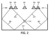
図2は、変更されたスピーカシステムセットアップの例を例示する。この例では、フロントラウドスピーカー、すなわち、レフトフロントラウドスピーカー103、センターラウドスピーカー101及びライトフロントラウドスピーカー105は、リスニング位置111の前に音声イメージを供給する。しかしながら、図2のシステムでは、サラウンドサウンド信号は、ユーザの後方に配置される別々のラウドスピーカーにより供給されるのではなく、リスニング位置111の前に配置されるラウドスピーカー201、203により供給される。具体例では、レフトサラウンドスピーカ201は、レフトフロントスピーカ103に隣接して位置され、ライトサラウンドスピーカ203は、ライトフロントスピーカ105に隣接して位置される。
FIG. 2 illustrates an example of a modified speaker system setup. In this example, the front loudspeakers, ie, the left
この例において、サラウンドスピーカ201、203は、リスナーの後方への方向からリスニング位置111に到達するため後壁213及び側壁209、211により反射される音声信号205、207を放射するように設けられる。よって、リアサラウンドスピーカ201、203は、後方から発するようにリスナーに現れるサラウンド信号205、207を供給する。この効果は、壁209、211、213により反射されるように、リア音声信号205、207を放射することにより達成される。具体例において、サラウンドサウンド信号205、207は、2つの壁反射、すなわち、側壁209、211及び後壁213の反射を介して主にリスニング位置に到達する。しかしながら、他の実施例及びシナリオが、より少ない又はより多くの反射を含んでもよいことは理解されるだろう。例えば、サラウンド信号205、207は、側壁209、211の単一の反射によりリスニング位置111に到達するように放射され、これにより、ユーザのサイドに知覚される仮想音源を与えてもよい。
In this example, the
図2の例において、各空間チャネルは、それ自身の個々のスピーカにより放射される。説明されるアプローチは、ユーザの前に位置される、特に、フロントスピーカ101、103、105の1つと隣接している又は同じ位置にあるサラウンドスピーカ201、203を可能にしながら、効果的なサラウンド経験を可能にする。しかしながら、これは、更に、同じスピーカが空間チャネルの1つ以上をレンダリングするために用いられることを可能にする。よって、多くの実施例において、サラウンドスピーカ201、203は、また、フロントチャネルの1つをレンダリングするためにも用いられてもよい。
In the example of FIG. 2, each spatial channel is radiated by its own individual speaker. The approach described is an effective surround experience while allowing
具体例では、レフトサラウンドスピーカ201は、また、レフトフロントチャネルもレンダリングし、ライトサラウンドスピーカ203は、ライトフロントチャネルもレンダリングする。しかしながら、レフト及びライトのフロントチャネルは、これらが前方から、すなわち直接スピーカ位置から来るように現れるように(直接経路を介して)リスニング位置へ直接供給されなければならないので、フロントチャネルはサラウンドチャネルとは異なる方向にレンダリングされる。
In a specific example, the
従って、このように、レフトフロントスピーカ103及びライトフロントスピーカ105は取り外されることができ、その代わりに、レフトサラウンドスピーカ201及びライトサラウンドスピーカ203が使用され、結果的に図3のシステムになる。図2及び図3の空間システムは、このように少なくともレフトサラウンドスピーカ201及びライトサラウンドスピーカ203による指向性音声放射線に基づいている。これは、例えば、所望の方向に角度を付けられた指向性ドライバユニットを用いて達成されるが、より頻繁にはビームを誘導できる振動子アレイを用いて達成される。よって、レフトサラウンドスピーカ201及びライトサラウンドスピーカ203の各々は、所望のビーム形成、よって指向性を供給するために、異なって(フェーズ及び/又は振幅)重み付けさせた及び/又は駆動信号を遅延させた複数の振動子ユニットを有する。
Therefore, the left
更にまた、システムの全ては、音声環境のジオメトリに強く依存するリスニング位置111で、空間音声経験を提供する。特に、部屋ジオメトリは、知覚される空間音に影響を及ぼす。特に、図2及び図3のサラウンドチャネルの空間知覚は、壁の反射により達成され、よって特定の部屋ジオメトリに非常に強く依存している。
Furthermore, all of the systems provide a spatial audio experience at listening
従って、音声再生システムを特定の音環境及び特に部屋ジオメトリに適応させて調整することは重要である。これは、しばしば、手動で又は半自動的に、ユーザにマイクロホンをリスニング位置に置くことを要求し、専用の調整プロセスを実施して達成される。しかしながら、これは、多くの一般的ユーザにとって複雑で時間がかかり、混乱させて非実用的な傾向がある。 Therefore, it is important to adjust the sound reproduction system to adapt to the specific sound environment and especially the room geometry. This is often accomplished manually or semi-automatically, requiring the user to place the microphone in the listening position and performing a dedicated adjustment process. However, this tends to be complex, time consuming, confusing and impractical for many common users.
以下に、音声再生システムを特定の環境に対して調整可能にする部屋/音声環境ジオメトリの自動推定を生成できるシステムが説明されるだろう。当該システムは、超音波及び音声バンド信号と測定との組み合わせを使用する距離測定に基づく。 In the following, a system that can generate an automatic estimate of the room / sound environment geometry that makes the sound playback system tunable for a particular environment will be described. The system is based on distance measurements using a combination of ultrasound and audio band signals and measurements.
説明されるアプローチは、所与の方向に変調超音波信号を放射するために、パラメトリックラウドスピーカーを使用する。このように、(超音波ラウドスピーカーの形式の)超音波発信器は、音声バンドテスト信号により変調される高い強度の超音波の指向性が高いビームを投射する。超音波が空気を通じて広がるので、音声バンドテスト信号は、音の指向性が高いビームを形成するように復調される。この音声ビームが、壁、天井又は大きな対象物のような障壁に当たるとき、音声周波数の音は、幅広い範囲の角度で反射され、その後、発信器の近くに配置されている(標準音声マイクロホンのような)音声バンドセンサにより録音される。送信と反射された信号の受信との時間差は、このとき、反射させている/散乱させている対象物までの距離を識別するために用いられる。 The described approach uses a parametric loudspeaker to emit a modulated ultrasound signal in a given direction. Thus, an ultrasonic transmitter (in the form of an ultrasonic loudspeaker) projects a beam with a high directivity of high intensity ultrasound modulated by an audio band test signal. As the ultrasonic waves spread through the air, the audio band test signal is demodulated to form a beam with high sound directivity. When this sound beam hits a barrier such as a wall, ceiling or large object, sound frequency sound is reflected at a wide range of angles and is then placed close to the transmitter (such as a standard sound microphone). It is recorded by the voice band sensor. The time difference between transmission and reception of the reflected signal is then used to identify the distance to the reflecting / scattering object.
当該アプローチは一組の角度にわたるスキャンを実施するように用いられ、これにより、例えば、装置から部屋の壁及び/又は天井までの距離を計算可能にし、部屋の幾何学的なモデルを構築可能にする。この情報を使用して、その後、音声再生システムは、任意の所与の部屋及びリスニング位置に対する音声レンダリングを最適化するように調整できる。以下の説明は、部屋の壁の位置及び距離を決定することにより二次元の部屋ジオメトリの決定に焦点を当てるが、当該アプローチは、三次元部屋ジオメトリの決定に等しく適用できることは理解されるだろう。特に、説明されるアプローチが、例えば部屋の天井までの距離を決定するために等しく適当であることは理解されるだろう。 The approach can be used to perform a scan over a set of angles, allowing for example the calculation of the distance from the device to the wall and / or ceiling of the room and the construction of a geometric model of the room. To do. Using this information, the audio playback system can then be adjusted to optimize audio rendering for any given room and listening position. The following description focuses on the determination of the two-dimensional room geometry by determining the location and distance of the room walls, but it will be understood that the approach is equally applicable to the determination of the three-dimensional room geometry. . In particular, it will be appreciated that the approach described is equally suitable for determining the distance to the ceiling of a room, for example.
図4は、測定システムの例を更に詳細に例示する。システムは、超音波信号で音声バンドテスト信号を変調することにより超音波テスト信号を生成するテスト信号発生器401を有する。テスト信号発生器401は、変調超音波テスト信号を放射するパラメトリックラウドスピーカー403に結合される。
FIG. 4 illustrates an example measurement system in more detail. The system includes a
パラメトリックラウドスピーカーは、高い強度の超音波キャリア信号から音声周波数を復調するために空気の非線形特性を利用する音声装置である。超音波キャリア信号は、通常は非常に短い波長を持つ超音波キャリアである。超音波音響波が音の波長より非常に大きいサイズで振動子から投射されるとき、超音波の非常に狭いビームが作られる。超音波が空気を通じて広がるので、音声信号は超音波キャリア信号から復調される。特に、音声経路の非線形性は復調器として作用し、これにより、超音波キャリア信号を変調するために用いられた元の音声テスト信号を再形成できる。斯様な非線形性は、送信経路で自動的に起こる。特に、送信媒体としての空気は、本質的に、聞き取れるようになる超音波に結果としてなる非線形特性を呈する。よって、例において、空気自体の非線形特性によって、高い強度の超音波信号から音声復調が生じる。 A parametric loudspeaker is an audio device that utilizes the non-linear characteristics of air to demodulate audio frequency from a high intensity ultrasonic carrier signal. The ultrasound carrier signal is an ultrasound carrier that usually has a very short wavelength. When an ultrasonic acoustic wave is projected from a transducer with a size that is much larger than the wavelength of the sound, a very narrow beam of ultrasonic waves is created. As the ultrasound spreads through the air, the audio signal is demodulated from the ultrasound carrier signal. In particular, the non-linearity of the speech path acts as a demodulator, which can recreate the original speech test signal used to modulate the ultrasound carrier signal. Such non-linearity occurs automatically in the transmission path. In particular, air as a transmission medium inherently exhibits non-linear characteristics that result in ultrasound that becomes audible. Thus, in the example, speech demodulation occurs from a high intensity ultrasound signal due to the non-linear characteristics of the air itself.
復調された音声信号は、また、主要な超音波キャリアの堅いバンドリング(束)の結果として、高い指向性ビームを形成する。音源の高い指向性は、聞き取れる音が非常に特定の位置に向けることを可能にし、これは、距離を正確に推定するために非常に有利である。更にまた、パラメトリックラウドスピーカーは、コンパクトであって、追加のフォーカシングを必要とせずに、本質的に小さなスポットサイズを持つ。 The demodulated audio signal also forms a highly directional beam as a result of the tight bundling of the main ultrasonic carrier. The high directivity of the sound source allows the audible sound to be directed to a very specific position, which is very advantageous for accurately estimating the distance. Furthermore, parametric loudspeakers are compact and have essentially a small spot size without the need for additional focusing.
パラメトリックラウドスピーカーが非常に高い精度で部屋の任意のポイントに音声ビームを向けることができる一方、ビームが対象物に当たると、音声周波数成分は部屋の全体にわたって散乱される。マイクロホンがパラメートリック振動子と一致して配置される場合、これは反射された音声信号を検出する。このシステムは、超音波送信器及び受信器に基づく従来の超音波測距検出ソナーシステムと同様にみえる。鍵となる違いは、超音波ソナーシステムが超音波を送信及び受信するが、図4のシステムは、超音波を送信して、音声範囲信号を受信することである。超音波は、高い鏡面態様で壁から反射される。壁が発信器に対して垂直である場合、強い信号が受信器の方へ反射される。発信器と壁との間の角度がますます平行になるにつれて、信号は受信器から遠くに反射される。よって、SN比が劣化するし、また、超音波ビームの後続の反射が結果として受信器側で強い信号になって、異常な読み取りを生じるという潜在的危険もある。 While parametric loudspeakers can direct the sound beam to any point in the room with very high accuracy, the sound frequency components are scattered throughout the room when the beam hits the object. If the microphone is placed in coincidence with the parametric transducer, it detects the reflected audio signal. This system looks similar to a conventional ultrasonic ranging detection sonar system based on an ultrasonic transmitter and receiver. The key difference is that the ultrasonic sonar system transmits and receives ultrasonic waves, whereas the system of FIG. 4 transmits ultrasonic waves and receives audio range signals. Ultrasound is reflected from the wall in a highly specular manner. If the wall is perpendicular to the transmitter, a strong signal is reflected towards the receiver. As the angle between the transmitter and the wall becomes increasingly parallel, the signal is reflected farther away from the receiver. Thus, there is a potential danger that the signal-to-noise ratio will degrade and that subsequent reflections of the ultrasonic beam will result in a strong signal on the receiver side resulting in abnormal reading.
新規な方法は、超音波ビームを送信するが、音声周波数信号を受信する。高周波成分は低周波成分より鏡面的に散乱する傾向があり、実際に低周波成分は、ほぼ無指向性分散パターンで散乱される。反射された音声信号の多くが全方向的にほぼ反射されるので、振動子が壁との作る角度に関係なく、音は常に受信器の方へ反射される。従って、新規な方法は、常に、所与のビーム角度で壁又は反射している対象物までの最も近い距離を正確に決定可能である。 The new method transmits an ultrasonic beam but receives an audio frequency signal. High frequency components tend to scatter more specularly than low frequency components, and in fact, low frequency components are scattered in a nearly omnidirectional dispersion pattern. Since most of the reflected audio signal is substantially reflected in all directions, the sound is always reflected toward the receiver regardless of the angle formed by the vibrator with respect to the wall. Thus, the novel method can always accurately determine the closest distance to a wall or reflecting object at a given beam angle.
図4のシステムにおいて、パラメトリックラウドスピーカー403の出力は、音声周波数テスト信号で変調された超音波キャリアである。ラウドスピーカーから壁への送信の間、音声は、聞き取れる音声ビームを形成するために、非線形インタラクションにより超音波キャリア信号から復調される。よって、指向性が高く狭い音声信号が生成され、壁の方へ放射される。
In the system of FIG. 4, the output of the
音声ビームが当たる第1の障壁で、音声バンド信号は、部屋内に比較的均一に散乱し、よってパラメトリックラウドスピーカー403の方へも反射される。
At the first barrier hit by the sound beam, the sound band signal is scattered relatively uniformly in the room and is therefore reflected back towards the
図4のシステムは、更に、音声バンド捕捉信号を生成する音声バンドセンサ405を有する。具体例において、音声バンドセンサ405は、例えば1kHzより下から例えば8kHzより上までの帯域幅を持つ標準音声バンドマイクロホンである。よって、マイクロホン405は、音声バンド(の少なくとも一部)を捕えて、対応する電気的信号を生成する。対象物(壁)の反射/散乱は、結果的にマイクロホン405の方へ反射される復調された音声テスト信号となり、よって、捕えられた音声バンド信号は、変調超音波テスト信号の空気中の復調から生じる復調された反射された音声バンド信号を有する。
The system of FIG. 4 further includes an
マイクロホン405は、捕えられた音声バンド信号を受信する距離回路又はプロセッサ407に結合されている。プロセッサ407は、更に、テスト信号発生器401に結合され、プロセッサ407は、テスト信号発生器401から音声バンドテスト信号に対する反射された音声信号推定を受信する。特に、空気中での音声バンドテスト信号の非線形復調からの結果である音声信号に対応する反射された音声信号推定が決定される。よって、反射された音声信号推定と音声バンドテスト信号との違いは、音声経路(特に復調)の非線形性を反映する。
距離回路407は、その後、音声バンド捕捉信号と反射された音声信号推定との比較に応じて、特にこれらの相対的タイミングを比較することにより、パラメトリックラウドスピーカー403から対象物までの距離のための距離推定を生成するように処理する。
The
簡潔さ及び明快さのため、以下のアプローチは、最初に、これらの非線形効果が重要でないシナリオ、すなわち反射された音声信号推定が音声バンドテスト信号と同じであるシナリオに対して説明されるだろう。よって、斯様な実施例において、距離回路又はプロセッサ407に音声バンドテスト信号が直接供給される。
For the sake of brevity and clarity, the following approach will first be described for scenarios where these non-linear effects are not important, ie the scenario where the reflected speech signal estimate is the same as the speech band test signal . Thus, in such an embodiment, the audio band test signal is supplied directly to the distance circuit or
当該システムは、パラメトリックラウドスピーカー403からマイクロホン405までの経路長に対応する測定された遅延時間に基づいて、距離を決定する。特に、送信された信号と反射された信号との間の時間差を測定することにより、音速は、システムとその方向の反射している対象物/壁との間の距離を計算するために用いられる。
The system determines the distance based on the measured delay time corresponding to the path length from the
パラメトリックラウドスピーカー403及びマイクロホン405は、特に同じ位置に配置されてもよく、この場合、測定された経路長が距離の2倍に対応する。パラメトリックラウドスピーカー403とマイクロホン405との間の距離が増大するので、パラメトリックラウドスピーカー403とマイクロホン405との間のこの距離は、三角形を形成し、単純な幾何学的な関係(例えば図5を参照)を使用して距離が計算可能になることは、理解されるだろう。多くの実施例において、パラメトリックラウドスピーカー403とマイクロホン405との間の距離は非常に小さいので、推定された距離の影響は無視でき、距離は、経路長を2で割ったものとして単純に計算される。パラメトリックラウドスピーカー403とマイクロホン405との間の距離が測定されるべき最小距離の5―10%未満である場合、これは通常達成される。
The
簡潔さ及び明快さのため、以下の説明は、パラメトリックラウドスピーカー403及びマイクロホン405が完全に同じ位置に配置されると仮定するだろう。
For brevity and clarity, the following description will assume that the
距離を決定するために、距離プロセッサ407は、特に、雑音が多い測定されたデータから距離情報を得るために特に強固である傾向がある相関ベースの技術を使用する。
To determine the distance, the
特に、生成された音声テスト信号とマイクロホン405から捕捉された音声テスト信号とのクロス相関は、結果的に、時間サンプルTrに対応するクロス相関のピークになり、時間サンプルTrで、各エコーがマイクロホン405で受信され、すなわち、一つ以上の反射を有する経路は、結果的に、音声テスト信号が、対応する遅延を持ってマイクロホンに到達することになる。このように、ピークは、検出されて、経路長推定を決定するために用いられる。例えば図6の例に示されるように、多重反射を示すインパルス応答の幾つかのピークが通常ある。第1のピーク、T1は、第1の反射に対応する。これは、壁までの距離に関する情報を提供するために用いられる。他のピークは、多重反射に対応し、多重反射経路を決定するために用いられる。これは、例えば、部屋の高次のモデリングのために使われる。
In particular, the cross correlation between the audio test signal and the audio test signal captured from the
第1のピークT1のサンプル番号を(サンプリング周波数fSにより割ることにより)時間インデックスに変換し、その後音速(約340ms―1)で乗算することにより、全体の経路の推定が導出できる。
2Dα=(T1/fS)*340
By converting the sample number of the first peak T 1 into a time index (by dividing by the sampling frequency f S ) and then multiplying by the speed of sound (about 340 ms −1 ), an overall path estimate can be derived.
2D α = (T 1 / f S ) * 340
図6は、対数的掃引テスト信号及びパラメトリックスピーカを用いた典型的部屋内で得られる測定されたインパルス応答を例示する。最初の4000個のサンプルは、パラメトリックスピーカ403とマイクロホン403との間のカップリングのため「誤ったインパルス」を示す。これは、パラメートリックアレイ駆動電子回路に含まれる前処理のため、約2600個のサンプルにより遅延される。第1の「誤ったピーク」のインデックスを後続のピークから減算することは、音声経路のための実際の移動時間/経路遅延を与える。約6000個のサンプルの第1の大きなピークは、第1の反射による。より高次の反射は、後続の小さなピークを引き起こす。
FIG. 6 illustrates the measured impulse response obtained in a typical room using a logarithmic sweep test signal and a parametric speaker. The first 4000 samples show a “false impulse” due to the coupling between the
この例において、距離プロセッサ407は、相関ピークのタイミングに応じて、距離推定を決定する。相関ピークは、例えば、測定された相関応答のN番目の相関ピークとして選択され、ここで、Nは1、2、...である。多くの実施例において、第1の相関ピークは直接の結合に対応し、距離推定は第2の相関ピークのタイミングに応じて決定される。よって、距離推定は、所与の時間閾値/遅延の後発生する第1のピークのタイミングに応じて決定される。この遅延は、相関応答自体に基づいて決定され、例えば、これは、第1の(直接結合された)相関ピークの時間に対応するように設定されるか、又は、例えば測定されるべき最小距離の2倍に一致する遅延より更に小さく、パラメトリックラウドスピーカー403とマイクロホン405との間の最大予想される距離より大きい遅延に対応する予め定められた時間遅延に設定される。
In this example, the
同様に、多重反射のための経路長は、N=3,4,5...(又は、直接結合が十分に減衰されている場合は2)の値に対応する相関ピークのタイミングから、又は所与の遅延の後の反射から決定される。 Similarly, the path length for multiple reflections is N = 3,4,5. . . (Or 2 if the direct coupling is sufficiently attenuated) determined from the timing of the correlation peak corresponding to the value or from the reflection after a given delay.
当該アプローチは、多くのシナリオで、改良された距離推定を提供する。特に、当該アプローチは、従来のラウドスピーカーアレイを使用することに関連したロビング(lobbing)、スポットサイズ、帯域幅制限及びスピーカ(アレイ)サイズの課題を解決又は緩和する。実際、当該アプローチは、低減されたサイズ及び低コスト/複雑さを維持すると共に、距離決定のために用いられる指向性が高い音声放射線を供給できる低い複雑さのアプローチを可能にする。 This approach provides improved distance estimation in many scenarios. In particular, the approach solves or mitigates the problems of lobing, spot size, bandwidth limitations and speaker (array) size associated with using conventional loudspeaker arrays. In fact, the approach maintains a reduced size and low cost / complexity, and enables a low complexity approach that can provide highly directional sound radiation used for distance determination.
更にまた、当該アプローチは、超音波測距システムと通常は関連する課題の影響を受けない傾向にある。斯様な超音波測距システムは、超音波測距装置が図7に例示されるような反射している壁と直角をなすときの状況で良好に実施する。しかしながら、反射する表面が測距装置に対してある角度にあるとき、超音波テスト信号は、図8にて図示されるように、測距装置へ反射されない。よくても、これは、減少したSN比に結果としてなり、また、超音波ビームの後続の反射が受信器で強い信号に結果的になるという潜在的危険もある。よって、代わりに複数の反射に対応する、不正確又は誤った距離測定に結果としてなるという高い可能性がある。従って、超音波測距は、フレキシブルなシステムに適していなくて、しばしば、例えば自動部屋校正システムのために有効ではなく、手動処置及びオペレーションを必要とする。 Furthermore, the approach tends to be unaffected by issues normally associated with ultrasound ranging systems. Such an ultrasonic ranging system performs well in situations where the ultrasonic ranging device is perpendicular to the reflecting wall as illustrated in FIG. However, when the reflecting surface is at an angle to the ranging device, the ultrasonic test signal is not reflected to the ranging device, as illustrated in FIG. At best, this results in a reduced signal-to-noise ratio, and there is also the potential danger that subsequent reflections of the ultrasound beam will result in a strong signal at the receiver. Thus, there is a high probability that an inaccurate or incorrect distance measurement will result, corresponding to multiple reflections instead. Accordingly, ultrasonic ranging is not suitable for flexible systems and is often not effective for, for example, automatic room calibration systems and requires manual treatment and operation.
対照的に、説明されているアプローチは、超音波ビームを送信するが、音声周波数信号を受信する。高周波成分は低周波成分より鏡面的に散乱する傾向があり、実際に低周波成分は、ほぼ無指向性分散パターンで散乱される。これは、反射された音声信号の多くが図9に図示されるように、ほぼ全方向的に反射される図4のシステムで利用される。従って、パラメトリックスピーカ403が壁と形成する角度に関係なく、音は常にマイクロホン405の方へ反射される。従って、当該アプローチは、角度の変化に対してずっと頑強であり、通常は、所与のビーム角度で反射している対象物までの最も近い距離を正確に決定することが常に可能である。よって、当該システムは、例えば音声環境又は部屋ジオメトリを決定するときに用いられるような自動距離測定に特に適している。
In contrast, the described approach transmits an ultrasound beam but receives an audio frequency signal. High frequency components tend to scatter more specularly than low frequency components, and in fact, low frequency components are scattered in a nearly omnidirectional dispersion pattern. This is utilized in the system of FIG. 4 where much of the reflected audio signal is reflected almost omnidirectionally as illustrated in FIG. Therefore, the sound is always reflected toward the
更に詳細には、信号発生器401は、特定の場合に単一の超音波キャリアである超音波信号を生成する超音波生成器409を有する。超音波信号は、超音波範囲内の音を含み、特に20kHzより高い周波数帯域幅を持つ。具体例において、超音波信号発生器409は、このように、20kHzを超える周波数を持つ単一のトーンである超音波信号を生成する。
More specifically, the
信号発生器401は、更に、音声バンドテスト信号を生成する音声生成器411を有する。音声バンドテスト信号は、15kHzより低い周波数成分、通常は10kHzより低い周波数成分を有する。多くの実施例において、音声バンドテスト信号は、5kHz又は2kHzより低い周波数成分を有する。多くの実施例において、低い周波数に対して反射が益々無指向性であるので、低い周波数は有利である。しかしながら、高い周波数は、反射する表面上の入射音ビームの有利な指向性を提供する。従って、音声バンドテスト信号の正確な周波数構成は、個々の実施例の要件及び好みに依存する。
The
音声バンドテスト信号は、幾つかの実施例において、単一のトーン信号である。他の実施例では、音声バンドテスト信号は、増大された周波数帯域幅を持ち、例えば白色又はピンク雑音信号であり、例えば最大長さシーケンスとして生成される。別の例として、音声バンドテスト信号は、単一のトーンの(対数的な)掃引である。個々の実施例において使用される特定の信号は、特定の好み及び要件に合うように選択される。 The voice band test signal is a single tone signal in some embodiments. In other embodiments, the audio band test signal has an increased frequency bandwidth, eg, a white or pink noise signal, eg, generated as a maximum length sequence. As another example, the voice band test signal is a (logarithmic) sweep of a single tone. The specific signals used in the individual embodiments are selected to suit specific preferences and requirements.
音声生成器411は、更に、距離の決定用に、特に相関用に音声バンドテスト信号のコピーを受信する距離プロセッサ407に結合される。多くの実施例において、送信される音声バンドテスト信号は、相関のために使われる信号と同一でない。例えば、多くの実施例において、反射された音声信号推定が、超音波信号で変調される音声バンドテスト信号の代わりに使われる。
The
特に、音声生成器は、音声バンドテスト信号を生成し、その後、反射された音声信号推定を生成するために、予想される非線形性を音声バンドテスト信号に適用し、その後、反射された音声信号推定は、距離プロセッサ407へ供給されて、距離推定及び特に相関のために使われる。
In particular, the audio generator generates an audio band test signal and then applies the expected non-linearity to the audio band test signal to generate a reflected audio signal estimate and then the reflected audio signal The estimates are fed to the
等価的に、音声生成器411は、距離プロセッサ407により実施される相関に適している最初の音声信号を最初に生成してもよい。その後、音声生成器411は、超音波信号の変調の前に、最初の音声信号の前置補償を実施することにより、音声バンドテスト信号を生成するように実施し、ここで、前置補償は、音声経路の非線形効果を補償しようとしている。よって、斯様な例では、初めに生成された音声信号は、反射された音声信号推定として使われ、相関音声信号の前置補償バージョンが音声バンドテスト信号として使われる。
Equivalently, the
異なるアプローチが、特定実施例に依存する斯様な前置補償のために用いられてもよい。基本的に、非線形復調は、結果的に入力音声信号の変形されたバージョンになり、非相関で使用される所望の音声信号に対応するきれいな音声信号を達成するために、非線形逆フィルタが相関音声テストに適用されてもよい。空気中での復調の間、前置補償により作られる非線形歪みは、少なくとも部分的に相殺される。 Different approaches may be used for such pre-compensation depending on the particular embodiment. Basically, non-linear demodulation results in a modified version of the input audio signal, and a non-linear inverse filter is used to correlate the audio to achieve a clean audio signal corresponding to the desired audio signal used in decorrelation. May be applied to tests. During demodulation in air, non-linear distortion created by pre-compensation is at least partially offset.
パラメトリックラウドスピーカーの音声出力から非線形歪み成分を除去するための非線形逆フィルタリングオペレーションのための様々な特別なアプローチは、当業者に分かるので、簡潔さのため本願明細書において更に説明されないだろう。適切なアプローチの例は、Lee,K.及びGen,W. "Bandwidth-Efficient Recursive Pth-Order Equalisation for correcting Baseband Distortion in Parametric Loudspeakers" IEEE Trans. On Audio Speech and Language Proc. Vo14, No2. March2006と、Kite,T.D., Post J.T.及びHamilton M.F. "Parametric Array in Air: Distortion Reduction by Preprocessing "Proc 16th Int. Cong. Acoust., Vol. 2. June 1998とで見られる。 Various special approaches for non-linear inverse filtering operations to remove non-linear distortion components from the parametric loudspeaker audio output will be known to those skilled in the art and will not be further described herein for the sake of brevity. Examples of suitable approaches are Lee, K. and Gen, W. "Bandwidth-Efficient Recursive Pth-Order Equalisation for correcting Baseband Distortion in Parametric Loudspeakers" IEEE Trans. On Audio Speech and Language Proc. Vo14, No2. March2006, Kite, TD, Post JT and Hamilton MF “Parametric Array in Air: Distortion Reduction by Preprocessing” Proc 16 th Int. Cong. Acoust., Vol.
幾つかの実施例において、音声テスト信号は、好適には、500Hz、1kHz、2kHz、5kHz又は8kHz以上の帯域幅を持つ。 In some embodiments, the audio test signal preferably has a bandwidth of 500 Hz, 1 kHz, 2 kHz, 5 kHz, or 8 kHz or more.
広帯域の信号を使用することは、例えば、反射している対象物についての付加的情報を引き出すために用いられる。 Using a broadband signal is used, for example, to derive additional information about the reflecting object.
例えば、発明者は、マイクロホン405で受信されるスペクトル信号が反射する表面と音声ビームとの間の角度に依存していると気付いた。特に、対象物の表面が垂直なとき、高周波成分はマイクロホンの方へ強く反射されるだろう。しかしながら、オブジェクト表面に対するビーム角度が益々平行になるにつれて、マイクロホン405に達する反射されたビームの高周波成分は減少する。
For example, the inventor has realized that the spectral signal received by the
図4のシステムにおいて、距離プロセッサ407は、マイクロホン405からの音声バンド捕捉信号の周波数分布特性に応じて、超音波ビームの方向と対象物の反射する表面との間の角度推定を更に生成するように設けられる。幾つかの実施例において、マイクロホン信号は、(例えば、部屋がさもなければ十分に静かである場合)直接用いられてもよいし、又は、おそらく最初に処理されてもよい(例えば、フィルタリングされる)。
In the system of FIG. 4, the
具体例では、距離プロセッサ407は、相対的に高い高周波エネルギー濃度がより垂直な角度を示すような角度推定を生成するように設けられる。距離プロセッサ407は、より高い周波数の方へエネルギー濃度を増大させるのに対して90°の角度の方へ角度推定をバイアスする。
In a specific example, the
具体例として、距離プロセッサ407は、音声バンドテスト信号及び捕えられたマイクロホン信号両方に対する高周波間隔及び低周波間隔でのエネルギーを測定する。各周波数バンドの相対的な減衰の比率が、その後生成される。このとき、角度は、この比率の関数として決定される。例えば、比率は、比率を角度と関連づける予め定められた値の表の調査を実施するために用いられる。予め定められた値は、例えば製造又は設計フェーズの一部としての専用の測定プロセスにより生成されていてもよい。
As a specific example, the
発明者は、マイクロホン405で受信されるスペクトル信号が反射する表面のサイズに依存していることを更に理解した。実際、マイクロホンの方への反射の周波数応答は、ビームが散乱する対象物のサイズ及び形状に依存することが分かった。対象物が変調信号の音声波長と比較して大きい場合、信号の大部分はマイクロホン405へ(その音声周波数で)反射される。対象物が波長と比較して小さい場合、より少ない信号がマイクロホン405へ反射される。マイクロホンで捕えられる信号に特有の周波数に基づいて、距離プロセッサ407は、対象物に対するサイズ推定を生成できる。
The inventor has further understood that the spectral signal received by the
図4のシステムにおいて、距離プロセッサ407は、このように、音声バンド捕捉信号の周波数分布特性に応じて、対象物に対するサイズ推定を生成するように更に設けられている。幾つかの実施例において、マイクロホン信号は、(例えば、部屋がさもなければ十分に静かである場合)直接用いられてもよいし、又は、おそらく最初に処理されてもよい(例えば、フィルタリングされる)。
In the system of FIG. 4, the
具体例において、距離プロセッサ407は、相対的に高い低周波エネルギー濃度がより大きいサイズを示すようなサイズ推定を生成するように設けられる。距離プロセッサ407は、低い周波数の方へ増大させるエネルギー濃度に対して、より大きなサイズ推定の方へ角度推定をバイアスする。
In a specific example,
具体例として、距離プロセッサ407は、音声バンドテスト信号及び捕えられたマイクロホン信号両方に対する高周波間隔及び低周波間隔でのエネルギーを測定する。各周波数バンドの相対的な減衰の比率が、その後生成される。このとき、角度は、この比率の関数として決定される。例えば、比率は、比率を角度と関連づける予め定められた値の表の調査を実施するために用いられる。予め定められた値は、例えば製造又は設計フェーズの一部としての専用の測定プロセスにより生成されていてもよい。
As a specific example, the
図4のシステムは、具体的には、空間音声再生を制御し、自動的に適応させるために用いられる。図10は、図4のシステムを含む空間音声再生システムの例を例示する。 The system of FIG. 4 is specifically used to control and automatically adapt spatial audio playback. FIG. 10 illustrates an example of a spatial audio reproduction system including the system of FIG.
図4のシステムに加えて、空間音声再生システムは、例えば図1乃至図3に図示されるようなラウドスピーカーセットアップを使用して特に5つのチャネルサラウンドシステムである空間音響システム1001を有する。
In addition to the system of FIG. 4, the spatial audio playback system has a spatial
システムは、更に、図4の距離推定システムを制御し、このシステムから受信される距離推定に応じて空間音響システム1001を適応させるように設けられる音声環境回路1003を有する。
The system further includes an
特に、音声環境回路1003は、壁及び多くの異なる方向の他の対象物までの距離が決定できるように、超音波信号が放射される方向を繰り返し変化させるための機能を有する。
In particular, the
例えば、測定及び調整プロセスは、音声環境回路1003により超音波ビームを任意の角度、例えば−90度に向けて始まり、ここで、0度は音声レンダリングシステムに対して垂直である。その後、距離評価が、この方向において実施され、結果として生じる距離推定は、音声環境回路1003へ供給される。ビーム角度は、その後、逐次更新され、充分なデータが収集されるまで、測定プロセスは繰り返される。
For example, the measurement and adjustment process begins with the
通常は、音声再生ハードウェアは、部屋のコーナー又は壁と同一平面に置かれ、ユーザはシステムの前の領域を占有する。このために、適切な角度測定は、5又は10度の増加量で、―90度から+90度の範囲であろう。角度増加量がより細かいほど、多くのデータが、音声環境ジオメトリを決定するために利用できる。 Usually, the audio playback hardware is co-planar with the corners or walls of the room, and the user occupies the area in front of the system. For this reason, a suitable angle measurement would be in the range of -90 degrees to +90 degrees with an increment of 5 or 10 degrees. The finer the angle increment, the more data is available to determine the audio environment geometry.
ビームが向ける角度方向は、例えば、振動子を物理的に回転させることにより、又は、ビーム形成技術及び分割型振動子アレイを使用して電気的ステアリングを通じて制御できる。 The angular direction the beam is directed can be controlled, for example, by physically rotating the transducer or through electrical steering using beamforming techniques and split transducer arrays.
例えば、測定方向の変化は、モーター付ヒンジ結合メカニズム又はベアリング上にパラメトリックラウドスピーカー403を取り付けることにより達成できる。フィードバック制御システムを用いて、音声再生システムに対するビームの絶対の角度方向が、正確に制御できる。モーター付メカニズムは、部屋の十分なラスタスキャンを可能にするようにパラメトリックラウドスピーカー403を物理的に回転可能にする。
For example, a change in measurement direction can be achieved by mounting a
幾つかの実施例において、パラメトリックラウドスピーカーは、超音波振動子のアレイを有し、音声環境回路1003は、超音波振動子の相対的な遅延、フェーズ及びゲインの少なくとも1つを制御することにより第1の方向の値を制御するように設けられる。よって、音声環境回路1003は、放射された超音波信号のアクティブビーム形成を制御する。
In some embodiments, the parametric loudspeaker has an array of ultrasonic transducers, and the
例えば、振動子が音響信号を再生するフェーズを変えることにより、振動子のアレイの指向性を制御することは可能である。超音波振動子のアレイを利用して、パラメトリックラウドスピーカーは、このように、振動子アレイの方向を物理的に変えることなしに、主超音波キャリア信号が電子的に広範囲にわたる角度へ操縦可能なように構築できる。斯様な実施例は、部屋のラスタスキャンのために使われる。 For example, the directivity of the transducer array can be controlled by changing the phase in which the transducer reproduces an acoustic signal. Using an array of ultrasonic transducers, a parametric loudspeaker can thus steer the main ultrasonic carrier signal electronically to a wide range of angles without physically changing the direction of the transducer array. Can be constructed as follows. Such an embodiment is used for room raster scans.
異なる方向に対する距離測定に基づいて、音声環境回路1003は、空間音響システム1001のための音声環境ジオメトリを推定する。この例では、音声環境回路1003は、このように部屋ジオメトリを推定する。
Based on distance measurements for different directions, the
例えば、音声環境回路1003は、モデル化された壁をデータに適合させるために、最適化アルゴリズムを用いて部屋の数値的モデルを構築する。幾つかの場合、長方形のような正多角形が、測定データに適合できる。幾つかの部屋は不規則な形状及び湾曲壁を持つので、これがいつも当てはまるわけではない。斯様な状況の下で、各壁は、帰納的なアルゴリズムで個別にデータに適合される。
For example, the
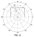
図11は、パラメトリックラウドスピーカーと壁との間の距離を識別するために対数的掃引方法及びピークの抽出を使用した実際の部屋測定の結果を示す。部屋を表わす最善の適合した長方形1101が、測定されたデータ1103と共に例示されている。トータルで19回の測定が、―90度から90度までの範囲で10度ずつなされた。1次の反射だけが考慮され、相関インパルス応答の他の全てのピークは無視された。モデルは、0.1mの範囲内でパラメトリックラウドスピーカーに対する壁位置を予測した。この場合、パラメトリックラウドスピーカーの後ろの壁は測定されなかった。リスナーがラウドスピーカーシステムの前にいるので、後壁の影響は、通常は、リスナーにより知覚される空間イメージ上でほとんど効果を持たない。
FIG. 11 shows the results of an actual room measurement using a logarithmic sweep method and peak extraction to identify the distance between the parametric loudspeaker and the wall. The best
音声環境(特に部屋)のジオメトリが決定されると、音声環境回路1003は、空間音響システム1001をこの環境に自動的に適応させる。
When the geometry of the audio environment (especially the room) is determined, the
例えば、図2及び図3に例示されるような空間経験を供給するため反射される音声を使用する空間音声再生システムに対して、音声ビームがユーザに到達する前に、最後の反射ポイントから反射された音は、音源の原点であるとリスナーにより知覚される。空間経験(例えばホームシネマ経験)を最適化するために、反射ポイントは慎重に選択される必要があり、よって、放射される音声ビームは、特定の音声環境に合うように正確に制御されるべきである。空間音響システムのラウドスピーカー及び(おそらく推定される)リスニング位置に対する壁の相対的な位置が知られるときだけ、これは可能である。これは、推定された部屋ジオメトリに基づいて実施でき、よって、図10のシステムは、空間音響システム1001の自動又は半分自動セットアップを実行する。
For example, for a spatial audio playback system that uses reflected audio to provide spatial experience as illustrated in FIGS. 2 and 3, the sound beam is reflected from the last reflection point before reaching the user. The perceived sound is perceived by the listener as being the origin of the sound source. In order to optimize the spatial experience (eg home cinema experience), the reflection points need to be chosen carefully, so the emitted sound beam should be precisely controlled to suit the particular sound environment It is. This is possible only when the position of the wall relative to the loudspeaker and the (possibly estimated) listening position of the spatial acoustic system is known. This can be done based on the estimated room geometry, so the system of FIG. 10 performs an automatic or semi-automatic setup of the spatial
説明されるシステムは、ホームシネマサウンドバーシステムのような離散的マルチチャネルラウドスピーカーシステムを代行しようとするコンパクト音響システムのために特に有益である。幾何学的な部屋モデルは、スピーカシステムがラウドスピーカーシステムのパラメータを部屋ジオメトリに最も合わせるように調整可能であり、例えば、非常に広いリスニング経験を提供するように超音波ビームの角度方向を調整することにより、最善の主観的な空間効果を提供する。 The described system is particularly beneficial for compact acoustic systems that seek to substitute discrete multi-channel loudspeaker systems such as home cinema soundbar systems. The geometric room model can be adjusted so that the loudspeaker system best matches the loudspeaker system parameters to the room geometry, for example, adjusting the angular orientation of the ultrasound beam to provide a very wide listening experience By providing the best subjective spatial effect.
幾つかの実施例において、音声環境の推定は、より複雑なアルゴリズムに基づき、より特定の情報を考慮してもよい。例えば、放射される音声ビームと反射する表面の間の角度の推定は、壁が測定に対応する角度にあるように、部屋をモデル化するために用いられる。この情報は、部屋ジオメトリを識別するように設計されたアルゴリズムの正確さ及び速さを劇的に増大させる。 In some embodiments, the estimation of the speech environment may be based on more complex algorithms and consider more specific information. For example, an estimate of the angle between the emitted sound beam and the reflecting surface is used to model the room so that the wall is at an angle corresponding to the measurement. This information dramatically increases the accuracy and speed of algorithms designed to identify room geometry.
更にまた、前述されたように、他の相関ピークは、パラメトリックスピーカと音声バンドセンサとの間の複数の反射を含む音声経路に対する多重反射距離推定を生成するために用いられる。これらの多重反射経路距離は、その後付加的に、モデルを、利用可能な測定データに適合させるために用いられる。 Furthermore, as described above, other correlation peaks are used to generate a multiple reflection distance estimate for an audio path that includes multiple reflections between a parametric speaker and an audio band sensor. These multiple reflection path distances are then additionally used to fit the model to the available measurement data.
例えば、測定されたデータが特に雑音が多い、又は、あまりにも少ない角度測定がなされた場合、再構成の正確さを増大することは、より高次の反射データを使用することを必要とする。これは、例えば、1次の部屋モデルを決定するために、単一の反射距離推定を最初に考慮することによりなされる。多重反射は、放射線トレーシングを使用して、1次の部屋モデルに適合され、モデルは、測定された多重反射距離との整合を改善するために修正される。 For example, if the measured data is particularly noisy or if too few angle measurements are made, increasing the accuracy of the reconstruction requires the use of higher order reflection data. This is done, for example, by first considering a single reflection distance estimate to determine a primary room model. Multiple reflections are fitted to a first order room model using radiation tracing, and the model is modified to improve alignment with the measured multiple reflection distance.
別の例として、例えば、低周波部屋モードのイコライゼーション(等価)及び予測のため、部屋サイズの正確なモデルが必要とされた場合、背壁の位置を推定することは可能である。これは、推定された多重反射経路距離を考慮しながら、高次の反射モデルを調べることにより達成される。 As another example, it is possible to estimate the position of the back wall when an accurate model of the room size is needed, eg, for equalization and prediction of low frequency room modes. This is achieved by examining higher order reflection models, taking into account the estimated multiple reflection path distance.
幾つかの実施例において、音声環境回路1003は、音声環境に対する残響時間も決定し、音声環境ジオメトリを決定するために残響時間を使用する。残響時間は、その出発値より例えば―60dBの強度まで音が減衰するのにかかる時間を表わし、部屋ボリュームに強く結合されている。残響時間は、測定されたインパルス応答から自由に計算できる。残響時間を測定するためのアプローチの例は、例えば、文献Schroeder M. R., "New Method of Measuring Reverberation Time", J. Acoust. Soc. Am. 1965, and Schroeder M.R., "Integrated- Impulse method measuring sound decay without using impulses", J. Acoust. Soc. Am. Vol. 66 (2) 1979で見られる。測定された残響時間は、具体的には、部屋の可能性があるボリュームに対する境界を設定するために用いられ、モデルはこの制約の下で適合できる。
In some embodiments, the
多くの実施例において、パラメトリックラウドスピーカー403及びマイクロホン405は、空間音響システム1001から独立している。しかしながら、幾つかの実施例において、同じ機能が、距離測定のため及び空間音響システム1001の通常動作両方のために使われている。
In many embodiments,
特に、幾つかの実施例において、パラメトリックスピーカ403は、少なくとも一つの空間チャネルのための音を再生するためにも用いられる。特に、パラメトリックスピーカ403は、壁の反射により空間音響システム1001のサラウンドチャネルのための音を再生するために用いられる。斯様な場合、パラメトリックラウドスピーカー403は既に空間音響システムの一部であるので、空間音響システム1001の説明された自動調整及び適合を実施するために必要とされる唯一の追加は、マイクロホン403及び付随する電子回路並びにソフトウェアパッケージであろう。
In particular, in some embodiments, the
サラウンドチャネルを生成するためのパラメトリックスピーカを使用している空間音響システム1001の例が、図2を参照して説明されている。
An example of a spatial
図2のシステムにおいて、サラウンドサウンド信号205、207は、具体的には、従来の音声信号ではなく、むしろ超音波信号として放射される。よって、当該システムは、超音波サラウンドサウンド信号205、207を放射するパラメトリックラウドスピーカーを使用する。 In the system of FIG. 2, the surround sound signals 205, 207 are specifically emitted as ultrasound signals rather than conventional audio signals. Thus, the system uses parametric loudspeakers that emit ultrasonic surround sound signals 205, 207.
斯様な指向性が高いビームは非常によく制御でき、図2のシステムにおいて、当該ビームは、部屋の壁209―213の明確な反射を介してリスニング位置111の方向に向けられ、生成された部屋ジオメトリモデルに基づいて制御できる。反射された音は、部屋の後ろに位置する音源を持つという知覚をリスナーに与えて、耳に到達する。
Such a highly directional beam is very well controllable and in the system of FIG. 2 the beam is directed and generated in the direction of the
このように、図2のシステムは、リスニング位置111の前に位置されるサラウンドスピーカ201、203として又はその一部として、指向性が高い音声ビームを持つ超音波振動子/パラメトリックラウドスピーカーを使用する。この超音波ビームは、反射された音が部屋の後ろに配置される音源を持つという知覚を提供するようにリスナーの耳に到達するように、部屋のサイド又は背壁209―213へ容易に向けられる。同じ超音波振動子/パラメトリックラウドスピーカーが、距離測定を実施するために使用できる。
Thus, the system of FIG. 2 uses an ultrasonic transducer / parametric loudspeaker with a highly directional sound beam as or as part of the
超音波信号205、207は、サラウンドチャネルの音声信号により超音波キャリア信号を振幅変調することにより生成される。この変調信号は、その後サラウンドスピーカ201、203から放射される。超音波信号は、人であるリスナーにより直接知覚されないが、変調している音声信号は、超音波キャリア信号を調整するために用いた元の音声信号を再形成するため、非線形性により復調できる。よって、超音波信号は、音声の音をリスナーに提供するために、自動的に復調される。
The
音声放射のための超音波振動子の使用の例及び他の説明は、例えば、PhD thesis "Sound from Ultrasound: The Parametric Array as an Audible Sound Source" by F. Joseph Pompei, 2002, Massachusetts Institute of Technologyで見つけられる。 Examples and other explanations of the use of ultrasonic transducers for sound radiation are given, for example, in PhD thesis "Sound from Ultrasound: The Parametric Array as an Audible Sound Source" by F. Joseph Pompei, 2002, Massachusetts Institute of Technology. can be found.
サラウンドチャネルの超音波放射の使用は、非常に狭いビームを供給する。これは、より良く規定され且つ制御される反射を可能にし、特に、リスニング位置への到着の角度の正確な制御を提供できる。よって、当該アプローチは、サラウンド音源の仮想知覚位置が非常によく規定され且つ制御可能にされる。更にまた、超音波信号の使用は、斯様な位置がポイント源により近いと知覚される、不鮮明さを少なくできる。また、超音波振動子の狭いビームは、他の経路に沿った音の放射を低減し、特に直接経路を通ってリスニング位置に達する何れの音の音量レベルも低下させる。更にまた、説明された正確な部屋モデル化と組み合わせて、これは、特定の部屋ジオメトリに密接に従うことに適している。 The use of surround channel ultrasonic radiation provides a very narrow beam. This allows for a better defined and controlled reflection and in particular can provide an accurate control of the angle of arrival at the listening position. The approach thus makes the virtual perceived position of the surround sound source very well defined and controllable. Furthermore, the use of ultrasound signals can reduce the smearing that such a position is perceived as closer to the point source. Also, the narrow beam of the ultrasonic transducer reduces the sound emission along other paths, especially the volume level of any sound that reaches the listening position through the direct path. Furthermore, in combination with the exact room modeling described, this is suitable for closely following a specific room geometry.
具体例において、サラウンドラウドスピーカー201、203は、単に超音波振動子を含むだけでなく、又は超音波信号を放射するだけではない。むしろ、サラウンドラウドスピーカー201、203各々は、音声周波数範囲(即ち5―10kHz未満)の音を放射する音声レンジラウドスピーカーと、壁205、207の方へ超音波を放射するための指向性超音波振動子との両方を含むスピーカアレンジメントを有する。
In a specific example, the
特に、斯様な超音波アプローチの使用から生じる音声の音質は、幾つかの実施例及びシナリオにおいて、変調している音声を聞けるようにレンダリングするために超音波キャリアが復調されるプロセスが、非効率的で本質的に非線形でない傾向があるので、最適でない。従って、超音波ラウドスピーカーは、通常は次善の音質を作る傾向があって、また低いパワー処理キャパシティを持つ傾向があり、これにより高い音量レベルを作ることを困難にしている。 In particular, the sound quality that results from the use of such an ultrasound approach is determined by the fact that in some embodiments and scenarios, the process by which the ultrasound carrier is demodulated to render the modulated sound to be heard is non-deterministic. It is not optimal because it tends to be efficient and not non-linear. Therefore, ultrasonic loudspeakers usually tend to produce sub-optimal sound quality and also tend to have low power processing capacity, which makes it difficult to produce high volume levels.
図2のシステムにおいて、この効果は、サラウンドチャネルから幾らかの音を更に放射する電子ダイナミックなフロント発射ラウドスピーカーにより補足される超音波振動子により緩和される。この音声バンド信号放射線は、直接経路を介してリスニング位置111に達する。よって、反射された超音波信号205、207に加えて、サラウンドラウドスピーカー201、203は、また特に、直接経路によりリスナーに達する音声バンド信号215、217も生成する。
In the system of FIG. 2, this effect is mitigated by an ultrasonic transducer supplemented by an electronic dynamic front firing loudspeaker that further radiates some sound from the surround channel. This voice band signal radiation reaches the
指向性超音波振動子を補足する音声レンジラウドスピーカーの使用は、多くの実施例において、改良された音質を提供する。特に、これは、低い周波数で改良された音質を提供する。斯様な低い周波数は、高い周波数ほど多くの空間キューを通常提供せず、従ってリスナーは、後方から到着するサラウンドサウンドを依然知覚し、すなわち後方への仮想音源が依然あると知覚する。更にまた、音声バンド信号は、主空間キューが反射された信号により供給されるように、反射された経路に対して遅れる。 The use of an audio range loudspeaker that supplements a directional ultrasonic transducer provides improved sound quality in many embodiments. In particular, this provides improved sound quality at low frequencies. Such low frequencies usually do not provide as many spatial cues as higher frequencies, so the listener still perceives the surround sound arriving from behind, i.e., there is still a virtual sound source behind. Furthermore, the audio band signal is delayed with respect to the reflected path so that the main space cue is provided by the reflected signal.
斯様なアプローチの詳細は、ヨーロッパ特許出願公開公報EP09162007.0に見られる。 Details of such an approach can be found in European Patent Application Publication No. EP 09162007.0.
幾つかの実施例では、音声環境回路1003は、また、リスニング位置を推定するように動作可能である。特に、音声環境回路1003は、ユーザが発する音を有するマイクロホン407から捕えられた信号を受信するように設けられ、その後、当該信号に応じてリスニング位置及び音声環境ジオメトリ(特に部屋モデル)を決定する。
In some embodiments, the
例えば、ユーザに手拍子のような衝動的な音をたてることを促すことにより、新しく識別される部屋モデルを使用するユーザ位置を決定することは、可能である。手拍子の衝動的な性質は、減少する振幅の一連の鋭いピークから作られる信号をマイクロホン403で生じさせる。第1のピークは、リスナーからマイクロホンへの直接的な音に起因し、次のピークは、部屋境界による後続する反射から生じる。インパルス列がユーザ及びマイクロホン405に対する壁位置により決定されるので、各リスニング位置は固有の信号を生じさせる。最適化ルーチンを用いて、ユーザ位置は、部屋の数値的モデル及び固有のパルス列信号の数から推定できる。
For example, it is possible to determine the user location to use the newly identified room model by prompting the user to make an impulsive sound such as clapping. The impulsive nature of the clapping produces a signal at the
代わりに、部屋ジオメトリに対する音響システムの方向は、最もありそうなリスニング領域を推定するために用いられる。例えばホームシネマアプリケーションのために、リスナーは、しばしば直接テレビの前に着席する。音声再生システムがテレビと位置合わせされていると仮定すると、リスニングゾーンは、専用の測定なしで推定できる。 Instead, the orientation of the acoustic system relative to the room geometry is used to estimate the most likely listening area. For example, for home cinema applications, listeners often sit directly in front of the television. Assuming that the audio playback system is aligned with the television, the listening zone can be estimated without dedicated measurements.
幾つかの実施例において、音声環境回路1003は、更に、対応する方向に対する距離推定の動的な変化を考慮するように設けられる。例えば、実質的に同一である(又は、閾値より少ない差がある)距離推定の動的な変化が、決定されて考慮される。例えば、所与の方向の距離推定は、特定の時間間隔で何度も繰り返される。これらの測定の幾つかは、他より短い距離に結果としてなり、これは、装置と対応する壁との間を通過する対象物に起因する。従って、音声環境回路1003は、部屋ジオメトリを決定するとき、このことを考慮に入れる。
In some embodiments, the
一例として、システムは、何度も、測定プロセスを繰り返す。例えば、(例えば−90°から+90°までの)掃引は、何度も(又は連続的に)繰り返される。この場合、ユーザ又は他の移動対象物が異なるスキャンに対して変化する動的な信号を生成する一方、壁のような固定の対象物は固定の背景を提供する。この動的な変化は、例えばあまりに多くの動的な変化を示す測定を無視することにより、部屋ジオメトリを決定するとき使われる。よって、音声環境回路1003は、距離推定の動的な変化に応じて音声環境ジオメトリを推定するように設けられる。
As an example, the system repeats the measurement process many times. For example, the sweep (eg, from −90 ° to + 90 °) is repeated many times (or continuously). In this case, a fixed object such as a wall provides a fixed background while a user or other moving object generates a dynamic signal that changes for different scans. This dynamic change is used when determining room geometry, for example by ignoring measurements that show too much dynamic change. Therefore, the
幾つかの実施例では、音声環境回路1003は、代わりに又は追加的に、リスニング位置を決定するために動的な変化を使用する。よって、音声環境回路1003は、距離推定の動的な変化に応じて、リスニング位置を推定するように設けられる。
In some embodiments, the
例えば、ユーザは、比較的短い時間の間ではあるが、空間音響システム1001を使用するとき、しばらくの間静的である傾向があるので、音声環境回路1003は、距離測定が適当な時間的変化を持つ動的な変化を示す方向を探索する。例えば、時間の80―90%に対して5メートル、大部分の残り時間の間に対して3メートルの距離推定を提供する方向が、リスニング位置に対応していそうであるとみなされる。実際には、もっと複雑な基準が適用できることは理解されるだろう。加えて、サイズ推定は、検出される対象物が人間に対応するサイズを持ちそうであるかどうかを推定するために用いられる。
For example, since the user tends to be static for a while when using the spatial
従って、リスニング位置は、部屋の複数のラスタスキャンを実施し、動的な信号を抽出することにより識別できる。動的なデータは、最もありそうなリスニング位置を外挿するために用いられる。 Thus, the listening position can be identified by performing multiple raster scans of the room and extracting dynamic signals. The dynamic data is used to extrapolate the most likely listening position.
上述の説明において、音速が、距離を推定するために使われた。多くの実施例において、予め定められた音速が使われる。しかしながら、幾つかの実施例において、装置は、測定に基づいて音速を推定し、推定に応じて距離を決定するように設けられてもよい。 In the above description, the speed of sound was used to estimate the distance. In many embodiments, a predetermined sound speed is used. However, in some embodiments, the apparatus may be provided to estimate the speed of sound based on the measurements and to determine the distance in response to the estimation.
実際には、ホームシネマセットアップのようなアプリケーションでは、音速のための単純な公称値(例えば340ms―1)で達成できる正確さは、充分でありそうである。しかしながら、より一般的な距離測定において、より正確な距離推定を持つことが望ましく、従って、空気の温度、高度及び湿度に依存する周囲音速を測定することは有効である。よって、装置は、特定の音声環境での周囲音速のより正確な推定を提供するため関連したパラメータを測定するための機能を有する。例えば、温度計は、温度を測定し、良く知られた式/関係に基づいて速度推定を調整するために用いられる。湿度及び大気圧が測定される場合、推定は更に改善できる。 In practice, in applications such as home cinema setups, the accuracy that can be achieved with a simple nominal value for the speed of sound (eg, 340 ms −1 ) is likely to be sufficient. However, in more general distance measurements, it is desirable to have a more accurate distance estimate, so it is useful to measure ambient sound speeds that depend on air temperature, altitude and humidity. Thus, the device has the capability to measure relevant parameters to provide a more accurate estimate of ambient sound speed in a particular voice environment. For example, a thermometer is used to measure temperature and adjust speed estimates based on well-known equations / relationships. If humidity and atmospheric pressure are measured, the estimation can be further improved.
周囲音速を測定する他の方法は、音が一定距離を移動するのにかかる時間の測定を含む。例えば、システムの配置が既知である場合、マイクロホンとラウドスピーカーとの間の相対的な距離は既知である。この情報を使用して、移動の測定された時間及び標準距離時間関係から音速を決定することは可能である。 Other methods of measuring ambient sound speed include measuring the time it takes for the sound to travel a certain distance. For example, if the arrangement of the system is known, the relative distance between the microphone and the loudspeaker is known. Using this information, it is possible to determine the speed of sound from the measured time of travel and the standard distance time relationship.
2つの超音波ラウドスピーカーがリアチャネルのために用いられるアプリケーションにおいて、複数の測定は、例えば平坦な壁/反射表面の特定の領域にわたって両方のラウドスピーカーを使用してなされる。充分なデータが収集される場合、異なる角度での時間の相互依存測定のセットが得られる。アクティブなコンポーネントの既知の配置に従って、このデータを数学モデルに入力することは、音速のための1つの値によってだけ満足できる関係を発現可能にする。この速度は、その後、距離の決定のために使われる。 In applications where two ultrasonic loudspeakers are used for the rear channel, multiple measurements are made using both loudspeakers over a specific area of, for example, a flat wall / reflective surface. If enough data is collected, a set of time-dependent measurements at different angles is obtained. Entering this data into the mathematical model according to the known arrangement of active components allows a relationship that can be satisfied only by one value for the speed of sound. This speed is then used for distance determination.
幾つかの実施例において、装置は、更に、パラメトリックラウドスピーカー403から放射される超音波信号を有する検出超音波信号を捕えるための手段を有する。このような実施例では、距離測定は、更に、この検出超音波信号に応じている。代わりに又は追加的に、第1の方向と対象物の反射する表面との間の角度推定は、検出超音波信号に応じて決定される。
In some embodiments, the apparatus further comprises means for capturing a detected ultrasound signal having an ultrasound signal emitted from the
よって、装置は、反射された超音波信号を測定するように設けられ、これにより距離測定のために使用できる第2の測定を提供する。これは、反射する表面がビーム方向に対して垂直に近いシナリオにおいて特に有利なパフォーマンスを提供する。 Thus, the device is provided to measure the reflected ultrasound signal, thereby providing a second measurement that can be used for distance measurement. This provides a particularly advantageous performance in scenarios where the reflecting surface is near perpendicular to the beam direction.
実際、90°近くの角度に対して、かなりの部分の超音波が反射され、これにより、超音波に基づいた正確な距離の決定を可能にする。しかしながら、90°から著しく離れた角度で、音声バンド検出は、低い超音波反射による最善の距離測定を提供する見込みがある。幾つかの実施例において、装置は、音声信号に基づいた距離推定、及び超音波信号に基づいた他の距離推定を決定する。最終的な距離推定は、例えば超音波信号の信号レベル(例えばパワー、エネルギー又は振幅)に依存する重みで、2つの推定の重み付けられた組合せとして決定される。 In fact, for an angle close to 90 °, a significant portion of the ultrasound is reflected, thereby allowing an accurate distance determination based on the ultrasound. However, at angles far from 90 °, audio band detection is likely to provide the best distance measurement with low ultrasonic reflection. In some embodiments, the apparatus determines a distance estimate based on the audio signal and other distance estimates based on the ultrasound signal. The final distance estimate is determined as a weighted combination of the two estimates, for example with a weight that depends on the signal level (eg power, energy or amplitude) of the ultrasound signal.
付加的な測定が、また、反射する表面の角度を推定するために用いられる。例えば、高濃度の超音波は表面が垂直なことを示すのに対し、低い信号レベルは、垂直から逸脱している角度を示す可能性がある。 Additional measurements are also used to estimate the angle of the reflecting surface. For example, a high concentration of ultrasound indicates that the surface is vertical, whereas a low signal level may indicate an angle that deviates from vertical.
明確さのため上記記載は、種々異なる機能的ユニット及びプロセッサを参照して、本発明の実施例を説明したことが理解されるだろう。しかしながら、異なる機能的ユニット又はプロセッサ間の機能の適当な配給が本発明から逸脱することなく使用されてもよいことは明らかである。例えば、別個のプロセッサ又はコントローラにより実施されるべき例示された機能は、同一のプロセッサ又はコントローラにより実施されてもよい。従って、特定の機能的ユニットの参照は、厳密な論理、物理的構造、又は組織を示すよりはむしろ、説明した機能を供給するための適当な手段の参照としてのみ見られるべきである。 It will be appreciated that, for clarity, the above description has described embodiments of the invention with reference to different functional units and processors. It will be apparent, however, that an appropriate distribution of functionality between different functional units or processors may be used without departing from the invention. For example, the illustrated functions to be performed by separate processors or controllers may be performed by the same processor or controller. Thus, a reference to a particular functional unit should only be seen as a reference to a suitable means for providing the described function, rather than to indicate the exact logic, physical structure, or organization.
本発明は、ハードウェア、ソフトウェア、ファームウェア又はこれらの組み合わせを含む適当な形式で実行できる。本発明は、オプション的に、一つ以上のデータプロセッサ及び/又はデジタル信号プロセッサを走らせるコンピュータソフトウェアとして少なくとも部分的に実行できる。本発明の実施例の要素及び部品は、適当な態様で物理的に、機能的に、及び論理的に実行されてもよい。実際に、機能は、単一のユニット、複数のユニット又は他の機能ユニットの一部で実行できる。このように、本発明は、単一のユニットで実行されてもよいし、異なるユニット及びプロセッサ間で物理的に、及び機能的に分配されてもよい。 The invention can be implemented in any suitable form including hardware, software, firmware or any combination of these. The invention can optionally be implemented at least partly as computer software running one or more data processors and / or digital signal processors. The elements and components of an embodiment of the invention may be physically, functionally and logically implemented in any suitable manner. Indeed, the functions can be performed on a single unit, multiple units or part of other functional units. Thus, the present invention may be implemented in a single unit or may be physically and functionally distributed between different units and processors.
本発明は幾つかの実施例と関連して説明されたが、ここで説明した特定の形式に限定する意図はない。むしろ、本発明の範囲は、添付の請求項によってのみ限定される。加えて、特徴が特定の実施例と関連して説明されるように見えるが、当業者は、説明された実施例の様々な特徴が本発明に従って組み合わされてもよいことを認識するだろう。請求項において、「有する」という用語は、他の要素又はステップの存在を排除しない。 Although the present invention has been described in connection with several embodiments, it is not intended to be limited to the specific form set forth herein. Rather, the scope of the present invention is limited only by the accompanying claims. In addition, although the features appear to be described in connection with a particular embodiment, those skilled in the art will recognize that the various features of the described embodiment may be combined in accordance with the present invention. In the claims, the term “comprising” does not exclude the presence of other elements or steps.
更に、個別にリストされているが、複数の手段、要素、又は方法のステップは、例えば単一のユニット又はプロセッサにより実行されてもよい。加えて、個別の特徴が異なる請求項に含まれているが、これらは好適に結合でき、異なる請求項に含まれるものは、特徴の組み合わせが実行可能及び/又は有益であるのではないということを意味しない。また、一つのカテゴリの請求項に特徴を含めることは、このカテゴリの制限を意味するのではなく、むしろ特徴が適当に他の請求項カテゴリに等しく適用可能であることを示す。更に、請求項の特徴の順番は、特徴が働かなければならない特定の順番を意味するのではなく、特に方法の請求項の個別のステップの順番は、ステップがこの順番で実施されなければならないことを意味しない。むしろ、ステップは適当な順番で実施されてもよい。加えて、単一の引用は複数を排除しない。よって、引用「a」、[an」、「第1の」、「第2の」等は、複数を排除しない。請求項内の参照符号は、単に例を明白にするものとして提供されるのであって、何れにおいても請求項の範囲を制限するものとして解釈されるべきではない。 Furthermore, although individually listed, a plurality of means, elements or method steps may be implemented by eg a single unit or processor. In addition, although individual features are included in different claims, they can be suitably combined and what is included in different claims means that a combination of features is not feasible and / or beneficial. Does not mean. Also, the inclusion of a feature in one category of claims does not imply a limitation of this category, but rather indicates that the feature is equally applicable to other claim categories. Further, the order of the features in the claims does not imply a particular order in which the features must work, and in particular the order of the individual steps in a method claim requires that the steps be performed in this order. Does not mean. Rather, the steps may be performed in any suitable order. In addition, a single citation does not exclude a plurality. Accordingly, the citations “a”, [an], “first”, “second” and the like do not exclude a plurality. Reference signs in the claims are provided merely as a clarifying example shall not be construed as limiting the scope of the claims in any way.
Claims (13)
Applications Claiming Priority (3)
| Application Number | Priority Date | Filing Date | Title |
|---|---|---|---|
| EP10163401.2 | 2010-05-20 | ||
| EP10163401 | 2010-05-20 | ||
| PCT/IB2011/052105 WO2011145030A1 (en) | 2010-05-20 | 2011-05-13 | Distance estimation using sound signals |
Publications (3)
| Publication Number | Publication Date |
|---|---|
| JP2013531785A JP2013531785A (en) | 2013-08-08 |
| JP2013531785A5 JP2013531785A5 (en) | 2014-06-26 |
| JP5894979B2 true JP5894979B2 (en) | 2016-03-30 |
Family
ID=44503241
Family Applications (1)
| Application Number | Title | Priority Date | Filing Date |
|---|---|---|---|
| JP2013510706A Active JP5894979B2 (en) | 2010-05-20 | 2011-05-13 | Distance estimation using speech signals |
Country Status (6)
| Country | Link |
|---|---|
| US (1) | US8811119B2 (en) |
| EP (1) | EP2572212B1 (en) |
| JP (1) | JP5894979B2 (en) |
| CN (1) | CN102893175B (en) |
| RU (1) | RU2576343C2 (en) |
| WO (1) | WO2011145030A1 (en) |
Families Citing this family (58)
| Publication number | Priority date | Publication date | Assignee | Title |
|---|---|---|---|---|
| JP5894979B2 (en) * | 2010-05-20 | 2016-03-30 | コーニンクレッカ フィリップス エヌ ヴェKoninklijke Philips N.V. | Distance estimation using speech signals |
| WO2012093345A1 (en) * | 2011-01-05 | 2012-07-12 | Koninklijke Philips Electronics N.V. | An audio system and method of operation therefor |
| US20140180629A1 (en) * | 2012-12-22 | 2014-06-26 | Ecole Polytechnique Federale De Lausanne Epfl | Method and a system for determining the geometry and/or the localization of an object |
| KR20150127174A (en) | 2013-03-14 | 2015-11-16 | 애플 인크. | Acoustic beacon for broadcasting the orientation of a device |
| US9909863B2 (en) | 2013-05-16 | 2018-03-06 | Koninklijke Philips N.V. | Determination of a room dimension estimate |
| JP6077957B2 (en) * | 2013-07-08 | 2017-02-08 | 本田技研工業株式会社 | Audio processing apparatus, audio processing method, and audio processing program |
| US9426598B2 (en) * | 2013-07-15 | 2016-08-23 | Dts, Inc. | Spatial calibration of surround sound systems including listener position estimation |
| JP6213916B2 (en) * | 2013-09-27 | 2017-10-18 | 国立大学法人九州工業大学 | Directional sound system |
| WO2015061345A2 (en) * | 2013-10-21 | 2015-04-30 | Turtle Beach Corporation | Directionally controllable parametric emitter |
| WO2015061347A1 (en) | 2013-10-21 | 2015-04-30 | Turtle Beach Corporation | Dynamic location determination for a directionally controllable parametric emitter |
| US10659889B2 (en) * | 2013-11-08 | 2020-05-19 | Infineon Technologies Ag | Microphone package and method for generating a microphone signal |
| CN103728589B (en) * | 2014-01-09 | 2016-05-11 | 上海京颐科技股份有限公司 | A kind of indoor orientation method |
| TW201538001A (en) * | 2014-03-18 | 2015-10-01 | Wistron Corp | Sound outputting device and equalizer adjusting method |
| WO2015182956A1 (en) | 2014-05-29 | 2015-12-03 | Samsung Electronics Co., Ltd. | Method and device for generating data representing structure of room |
| KR101642084B1 (en) * | 2014-05-29 | 2016-07-22 | 경희대학교 산학협력단 | Apparatus and method for detecting face using multiple source localization |
| JP6462308B2 (en) * | 2014-10-22 | 2019-01-30 | 株式会社デンソー | Object detection device |
| US10057706B2 (en) | 2014-11-26 | 2018-08-21 | Sony Interactive Entertainment Inc. | Information processing device, information processing system, control method, and program |
| US9319633B1 (en) | 2015-03-19 | 2016-04-19 | Cisco Technology, Inc. | Ultrasonic echo canceler-based technique to detect participant presence at a video conference endpoint |
| CN107533134B (en) * | 2015-04-15 | 2021-04-27 | 音频像素有限公司 | Camera, audio sound system, method and system for detecting position of object |
| CN106339068A (en) * | 2015-07-07 | 2017-01-18 | 西安中兴新软件有限责任公司 | Method and device for adjusting parameters |
| US10264383B1 (en) * | 2015-09-25 | 2019-04-16 | Apple Inc. | Multi-listener stereo image array |
| US10708701B2 (en) * | 2015-10-28 | 2020-07-07 | Music Tribe Global Brands Ltd. | Sound level estimation |
| US10154358B2 (en) * | 2015-11-18 | 2018-12-11 | Samsung Electronics Co., Ltd. | Audio apparatus adaptable to user position |
| CN105510918A (en) * | 2015-11-30 | 2016-04-20 | 湖南沄辉科技股份有限公司 | Actual measurement sound velocity-based ultrasonic distance measuring method and ultrasonic sensor |
| US9554091B1 (en) | 2015-12-15 | 2017-01-24 | Cisco Technology, Inc. | Identifying conference participants and active talkers at a video conference endpoint using user devices |
| US10605920B2 (en) * | 2016-01-13 | 2020-03-31 | Ams Sensors Singapore Pte. Ltd. | Power savings through refresh control for distance sensing devices |
| US10671826B2 (en) | 2016-02-08 | 2020-06-02 | Ideal Industries Lighting Llc | Indoor location services using a distributed lighting network |
| JP2017163432A (en) * | 2016-03-10 | 2017-09-14 | ソニー株式会社 | Information processor, information processing method and program |
| US9693169B1 (en) * | 2016-03-16 | 2017-06-27 | Sony Corporation | Ultrasonic speaker assembly with ultrasonic room mapping |
| US10945068B2 (en) | 2016-06-03 | 2021-03-09 | Huawei Technologies Co., Ltd. | Ultrasonic wave-based voice signal transmission system and method |
| US9881632B1 (en) * | 2017-01-04 | 2018-01-30 | 2236008 Ontario Inc. | System and method for echo suppression for in-car communications |
| CN106817654B (en) * | 2017-03-22 | 2019-10-22 | 微鲸科技有限公司 | Sound effect treatment method, device and multimedia equipment |
| KR101975423B1 (en) * | 2017-06-02 | 2019-05-07 | 네이버 주식회사 | Method and apparatus for providing appropriate information for location and space of user actively |
| TWI633276B (en) * | 2017-07-27 | 2018-08-21 | 宏碁股份有限公司 | Distance detection device and distance detection method thereof |
| TWI633275B (en) * | 2017-07-27 | 2018-08-21 | 宏碁股份有限公司 | Distance detection device and distance detection method thereof |
| CN109375199B (en) * | 2017-08-09 | 2022-12-06 | 宏碁股份有限公司 | Distance detection device and distance detection method thereof |
| CN110663173B (en) | 2017-10-04 | 2023-09-19 | 谷歌有限责任公司 | Method and system for automatically equalizing audio output based on room characteristics |
| KR102527278B1 (en) | 2017-12-04 | 2023-04-28 | 삼성전자주식회사 | Electronic apparatus, method for controlling thereof and the computer readable recording medium |
| US20190324117A1 (en) * | 2018-04-24 | 2019-10-24 | Mediatek Inc. | Content aware audio source localization |
| CN108668194A (en) * | 2018-05-11 | 2018-10-16 | 四川斐讯信息技术有限公司 | A kind of barrier localization method of intelligent sound box and its use environment |
| US10277981B1 (en) * | 2018-10-02 | 2019-04-30 | Sonos, Inc. | Systems and methods of user localization |
| US11184725B2 (en) | 2018-10-09 | 2021-11-23 | Samsung Electronics Co., Ltd. | Method and system for autonomous boundary detection for speakers |
| WO2020088861A1 (en) * | 2018-11-01 | 2020-05-07 | Arcelik Anonim Sirketi | Optimized adaptive bass frequency system in loudspeakers |
| TW202021377A (en) * | 2018-11-23 | 2020-06-01 | 廣達電腦股份有限公司 | Environmental detection system and sound control method using the same |
| CN109597312B (en) * | 2018-11-26 | 2022-03-01 | 北京小米移动软件有限公司 | Sound box control method and device |
| EP3909260A4 (en) | 2019-01-10 | 2022-10-05 | Parts Express International, Inc. | Measuring loudspeaker nonlinearity and asymmetry |
| US10959018B1 (en) * | 2019-01-18 | 2021-03-23 | Amazon Technologies, Inc. | Method for autonomous loudspeaker room adaptation |
| CN110072177B (en) | 2019-04-30 | 2022-04-08 | 北京小米智能科技有限公司 | Space division information acquisition method and device and storage medium |
| KR20200133632A (en) * | 2019-05-20 | 2020-11-30 | 삼성전자주식회사 | directional acoustic sensor and method of detecting distance from sound source using the directional acoustic sensor |
| WO2021002191A1 (en) * | 2019-07-01 | 2021-01-07 | ピクシーダストテクノロジーズ株式会社 | Audio controller, audio system, program, and method for controlling plurality of directive speakers |
| CN112213728A (en) * | 2019-07-11 | 2021-01-12 | 深圳市优必选科技股份有限公司 | Ultrasonic distance measurement method and device, computer readable storage medium and robot |
| CN112634884A (en) * | 2019-09-23 | 2021-04-09 | 北京声智科技有限公司 | Method of controlling output audio, method of outputting audio, apparatus, electronic device, and computer-readable storage medium |
| US11280760B2 (en) * | 2019-10-02 | 2022-03-22 | The Boeing Company | Apparatus and method for modulated-frequency ultrasonic inspection of structures |
| US11503563B2 (en) | 2020-02-04 | 2022-11-15 | Alibaba Group Holding Limited | Distance estimation using signals of different frequencies |
| WO2021246195A1 (en) * | 2020-06-05 | 2021-12-09 | ソニーグループ株式会社 | Signal processing device, method, and program |
| KR20220041432A (en) * | 2020-09-25 | 2022-04-01 | 삼성전자주식회사 | System and method for detecting distance using acoustic signal |
| TWI792205B (en) * | 2021-03-02 | 2023-02-11 | 瑞昱半導體股份有限公司 | Ultrasound-based audio playback method and ultrasound-based electronic device |
| CN114624689B (en) * | 2022-05-12 | 2022-09-23 | 杭州兆华电子股份有限公司 | Near-field focusing sound source distance calculation method and system based on acoustic imaging instrument |
Family Cites Families (20)
| Publication number | Priority date | Publication date | Assignee | Title |
|---|---|---|---|---|
| JP2572367B2 (en) * | 1989-10-16 | 1997-01-16 | 株式会社カイジョー | Abnormal wave elimination circuit of wave height meter |
| JPH03264883A (en) * | 1990-03-15 | 1991-11-26 | Matsushita Electric Works Ltd | Information apparatus |
| DE4238111A1 (en) | 1992-11-12 | 1994-05-19 | Atlas Elektronik Gmbh | Airborne echo sounder |
| JPH09211109A (en) * | 1996-02-05 | 1997-08-15 | Hitachi Zosen Corp | Parametric diffusion sonar |
| US6577738B2 (en) * | 1996-07-17 | 2003-06-10 | American Technology Corporation | Parametric virtual speaker and surround-sound system |
| JP3000982B2 (en) * | 1997-11-25 | 2000-01-17 | 日本電気株式会社 | Super directional speaker system and method of driving speaker system |
| JP3264249B2 (en) * | 1998-06-15 | 2002-03-11 | 日本電気株式会社 | Automatic orientation speaker system |
| JP2000050387A (en) | 1998-07-16 | 2000-02-18 | Massachusetts Inst Of Technol <Mit> | Parameteric audio system |
| GB0301093D0 (en) * | 2003-01-17 | 2003-02-19 | 1 Ltd | Set-up method for array-type sound systems |
| KR100707103B1 (en) * | 2004-06-09 | 2007-04-13 | 학교법인 포항공과대학교 | High directional ultrasonic ranging measurement system and method in air using parametric array |
| JP4214961B2 (en) * | 2004-06-28 | 2009-01-28 | セイコーエプソン株式会社 | Superdirective sound system and projector |
| JP2006194627A (en) * | 2005-01-11 | 2006-07-27 | Oki Electric Ind Co Ltd | Sound source position estimation method and device, and sonar |
| KR100781467B1 (en) * | 2006-07-13 | 2007-12-03 | 학교법인 포항공과대학교 | Mems based multiple resonances type ultrasonic transducer for ranging measurement with high directionality using parametric transmitting array in air |
| JP2008061137A (en) | 2006-09-01 | 2008-03-13 | Canon Inc | Acoustic reproducing apparatus and its control method |
| RU69646U1 (en) * | 2007-05-03 | 2007-12-27 | Технологический институт Федерального государственного образовательного учреждения высшего профессионального образования "Южный федеральный университет" в г. Таганроге (ТТИ ЮФУ) | PARAMETRIC ECHO-PULSE LOCATOR |
| GB0721313D0 (en) | 2007-10-31 | 2007-12-12 | 1 Ltd | Microphone based auto set-up |
| JP2009162498A (en) * | 2007-12-28 | 2009-07-23 | Ihi Corp | Survey/classification method and device for object under water bottom |
| KR100983744B1 (en) * | 2008-07-23 | 2010-09-24 | 포항공과대학교 산학협력단 | Sound wave generator for the application of the parametric array |
| RU2525109C2 (en) * | 2009-06-05 | 2014-08-10 | Конинклейке Филипс Электроникс Н.В. | Surround sound system and method therefor |
| JP5894979B2 (en) * | 2010-05-20 | 2016-03-30 | コーニンクレッカ フィリップス エヌ ヴェKoninklijke Philips N.V. | Distance estimation using speech signals |
-
2011
- 2011-05-13 JP JP2013510706A patent/JP5894979B2/en active Active
- 2011-05-13 US US13/698,401 patent/US8811119B2/en active Active
- 2011-05-13 CN CN201180024988.XA patent/CN102893175B/en active Active
- 2011-05-13 EP EP11723702.4A patent/EP2572212B1/en active Active
- 2011-05-13 WO PCT/IB2011/052105 patent/WO2011145030A1/en active Application Filing
- 2011-05-13 RU RU2012155185/28A patent/RU2576343C2/en active
Also Published As
| Publication number | Publication date |
|---|---|
| EP2572212B1 (en) | 2013-12-25 |
| CN102893175A (en) | 2013-01-23 |
| US20130064042A1 (en) | 2013-03-14 |
| JP2013531785A (en) | 2013-08-08 |
| RU2576343C2 (en) | 2016-02-27 |
| EP2572212A1 (en) | 2013-03-27 |
| RU2012155185A (en) | 2014-06-27 |
| US8811119B2 (en) | 2014-08-19 |
| WO2011145030A1 (en) | 2011-11-24 |
| CN102893175B (en) | 2014-10-29 |
Similar Documents
| Publication | Publication Date | Title |
|---|---|---|
| JP5894979B2 (en) | Distance estimation using speech signals | |
| US10433098B2 (en) | Apparatus and method for generating a filtered audio signal realizing elevation rendering | |
| EP3214859A1 (en) | Apparatus and method for determining delay and gain parameters for calibrating a multi channel audio system | |
| TWI700937B (en) | Room characterization and correction for multi-channel audio | |
| US20160105758A1 (en) | Sound source replication system | |
| US8594350B2 (en) | Set-up method for array-type sound system | |
| US9426598B2 (en) | Spatial calibration of surround sound systems including listener position estimation | |
| RU2419963C2 (en) | Method of correcting acoustic signal playback using electroacoustic transducer and device for implementing said method | |
| LV14747B (en) | Method and device for correction operating parameters of electro-acoustic radiators | |
| KR101646540B1 (en) | Converter and method for converting an audio signal | |
| JP2006517072A (en) | Method and apparatus for controlling playback unit using multi-channel signal | |
| EP2208369B1 (en) | Sound projector set-up | |
| JP2015070578A (en) | Acoustic control device | |
| Aarts et al. | Distance estimation using sound signals | |
| LV15137B (en) | Method and device for correction of sound |
Legal Events
| Date | Code | Title | Description |
|---|---|---|---|
| A521 | Request for written amendment filed |
Free format text: JAPANESE INTERMEDIATE CODE: A523 Effective date: 20140509 |
|
| A621 | Written request for application examination |
Free format text: JAPANESE INTERMEDIATE CODE: A621 Effective date: 20140509 |
|
| RD02 | Notification of acceptance of power of attorney |
Free format text: JAPANESE INTERMEDIATE CODE: A7422 Effective date: 20140509 |
|
| A977 | Report on retrieval |
Free format text: JAPANESE INTERMEDIATE CODE: A971007 Effective date: 20150115 |
|
| A131 | Notification of reasons for refusal |
Free format text: JAPANESE INTERMEDIATE CODE: A131 Effective date: 20150127 |
|
| A131 | Notification of reasons for refusal |
Free format text: JAPANESE INTERMEDIATE CODE: A131 Effective date: 20151006 |
|
| A521 | Request for written amendment filed |
Free format text: JAPANESE INTERMEDIATE CODE: A523 Effective date: 20151221 |
|
| TRDD | Decision of grant or rejection written | ||
| A01 | Written decision to grant a patent or to grant a registration (utility model) |
Free format text: JAPANESE INTERMEDIATE CODE: A01 Effective date: 20160203 |
|
| A61 | First payment of annual fees (during grant procedure) |
Free format text: JAPANESE INTERMEDIATE CODE: A61 Effective date: 20160229 |
|
| R150 | Certificate of patent or registration of utility model |
Ref document number: 5894979 Country of ref document: JP Free format text: JAPANESE INTERMEDIATE CODE: R150 |
|
| R250 | Receipt of annual fees |
Free format text: JAPANESE INTERMEDIATE CODE: R250 |
|
| R250 | Receipt of annual fees |
Free format text: JAPANESE INTERMEDIATE CODE: R250 |
|
| R250 | Receipt of annual fees |
Free format text: JAPANESE INTERMEDIATE CODE: R250 |
|
| R250 | Receipt of annual fees |
Free format text: JAPANESE INTERMEDIATE CODE: R250 |
|
| R250 | Receipt of annual fees |
Free format text: JAPANESE INTERMEDIATE CODE: R250 |
|
| R250 | Receipt of annual fees |
Free format text: JAPANESE INTERMEDIATE CODE: R250 |