JP5894962B2 - Image forming apparatus and method of controlling image forming apparatus - Google Patents
Image forming apparatus and method of controlling image forming apparatus Download PDFInfo
- Publication number
- JP5894962B2 JP5894962B2 JP2013094237A JP2013094237A JP5894962B2 JP 5894962 B2 JP5894962 B2 JP 5894962B2 JP 2013094237 A JP2013094237 A JP 2013094237A JP 2013094237 A JP2013094237 A JP 2013094237A JP 5894962 B2 JP5894962 B2 JP 5894962B2
- Authority
- JP
- Japan
- Prior art keywords
- image forming
- inspection
- light
- unit
- image
- Prior art date
- Legal status (The legal status is an assumption and is not a legal conclusion. Google has not performed a legal analysis and makes no representation as to the accuracy of the status listed.)
- Expired - Fee Related
Links
Images


Classifications
-
- H—ELECTRICITY
- H04—ELECTRIC COMMUNICATION TECHNIQUE
- H04N—PICTORIAL COMMUNICATION, e.g. TELEVISION
- H04N1/00—Scanning, transmission or reproduction of documents or the like, e.g. facsimile transmission; Details thereof
- H04N1/46—Colour picture communication systems
- H04N1/56—Processing of colour picture signals
- H04N1/60—Colour correction or control
- H04N1/603—Colour correction or control controlled by characteristics of the picture signal generator or the picture reproducer
- H04N1/6033—Colour correction or control controlled by characteristics of the picture signal generator or the picture reproducer using test pattern analysis
- H04N1/6044—Colour correction or control controlled by characteristics of the picture signal generator or the picture reproducer using test pattern analysis involving a sensor integrated in the machine or otherwise specifically adapted to read the test pattern
-
- G—PHYSICS
- G06—COMPUTING; CALCULATING OR COUNTING
- G06K—GRAPHICAL DATA READING; PRESENTATION OF DATA; RECORD CARRIERS; HANDLING RECORD CARRIERS
- G06K15/00—Arrangements for producing a permanent visual presentation of the output data, e.g. computer output printers
- G06K15/02—Arrangements for producing a permanent visual presentation of the output data, e.g. computer output printers using printers
- G06K15/027—Test patterns and calibration
-
- H—ELECTRICITY
- H04—ELECTRIC COMMUNICATION TECHNIQUE
- H04N—PICTORIAL COMMUNICATION, e.g. TELEVISION
- H04N1/00—Scanning, transmission or reproduction of documents or the like, e.g. facsimile transmission; Details thereof
- H04N1/46—Colour picture communication systems
- H04N1/56—Processing of colour picture signals
- H04N1/60—Colour correction or control
- H04N1/603—Colour correction or control controlled by characteristics of the picture signal generator or the picture reproducer
- H04N1/6033—Colour correction or control controlled by characteristics of the picture signal generator or the picture reproducer using test pattern analysis
-
- H—ELECTRICITY
- H04—ELECTRIC COMMUNICATION TECHNIQUE
- H04N—PICTORIAL COMMUNICATION, e.g. TELEVISION
- H04N2201/00—Indexing scheme relating to scanning, transmission or reproduction of documents or the like, and to details thereof
- H04N2201/04—Scanning arrangements
- H04N2201/047—Detection, control or error compensation of scanning velocity or position
- H04N2201/04701—Detection of scanning velocity or position
- H04N2201/0471—Detection of scanning velocity or position using dedicated detectors
- H04N2201/04712—Detection of scanning velocity or position using dedicated detectors using unbroken arrays of detectors, i.e. detectors mounted on the same substrate
-
- H—ELECTRICITY
- H04—ELECTRIC COMMUNICATION TECHNIQUE
- H04N—PICTORIAL COMMUNICATION, e.g. TELEVISION
- H04N2201/00—Indexing scheme relating to scanning, transmission or reproduction of documents or the like, and to details thereof
- H04N2201/04—Scanning arrangements
- H04N2201/047—Detection, control or error compensation of scanning velocity or position
- H04N2201/04701—Detection of scanning velocity or position
- H04N2201/04729—Detection of scanning velocity or position in the main-scan direction
-
- H—ELECTRICITY
- H04—ELECTRIC COMMUNICATION TECHNIQUE
- H04N—PICTORIAL COMMUNICATION, e.g. TELEVISION
- H04N2201/00—Indexing scheme relating to scanning, transmission or reproduction of documents or the like, and to details thereof
- H04N2201/04—Scanning arrangements
- H04N2201/047—Detection, control or error compensation of scanning velocity or position
- H04N2201/04701—Detection of scanning velocity or position
- H04N2201/04731—Detection of scanning velocity or position in the sub-scan direction
-
- H—ELECTRICITY
- H04—ELECTRIC COMMUNICATION TECHNIQUE
- H04N—PICTORIAL COMMUNICATION, e.g. TELEVISION
- H04N2201/00—Indexing scheme relating to scanning, transmission or reproduction of documents or the like, and to details thereof
- H04N2201/04—Scanning arrangements
- H04N2201/047—Detection, control or error compensation of scanning velocity or position
- H04N2201/04701—Detection of scanning velocity or position
- H04N2201/04732—Detecting at infrequent intervals, e.g. once or twice per line for main-scan control
-
- H—ELECTRICITY
- H04—ELECTRIC COMMUNICATION TECHNIQUE
- H04N—PICTORIAL COMMUNICATION, e.g. TELEVISION
- H04N2201/00—Indexing scheme relating to scanning, transmission or reproduction of documents or the like, and to details thereof
- H04N2201/04—Scanning arrangements
- H04N2201/047—Detection, control or error compensation of scanning velocity or position
- H04N2201/04701—Detection of scanning velocity or position
- H04N2201/04734—Detecting at frequent intervals, e.g. once per line for sub-scan control
-
- H—ELECTRICITY
- H04—ELECTRIC COMMUNICATION TECHNIQUE
- H04N—PICTORIAL COMMUNICATION, e.g. TELEVISION
- H04N2201/00—Indexing scheme relating to scanning, transmission or reproduction of documents or the like, and to details thereof
- H04N2201/04—Scanning arrangements
- H04N2201/047—Detection, control or error compensation of scanning velocity or position
- H04N2201/04701—Detection of scanning velocity or position
- H04N2201/04744—Detection of scanning velocity or position by detecting the scanned beam or a reference beam
-
- H—ELECTRICITY
- H04—ELECTRIC COMMUNICATION TECHNIQUE
- H04N—PICTORIAL COMMUNICATION, e.g. TELEVISION
- H04N2201/00—Indexing scheme relating to scanning, transmission or reproduction of documents or the like, and to details thereof
- H04N2201/04—Scanning arrangements
- H04N2201/047—Detection, control or error compensation of scanning velocity or position
- H04N2201/04753—Control or error compensation of scanning position or velocity
- H04N2201/04758—Control or error compensation of scanning position or velocity by controlling the position of the scanned image area
- H04N2201/04767—Control or error compensation of scanning position or velocity by controlling the position of the scanned image area by controlling the timing of the signals, e.g. by controlling the frequency o phase of the pixel clock
Description
本発明は、画像形成装置、及び画像形成装置の制御方法に関し、例えば、濃度補正を行うための濃度検出機構を備える電子写真式のプリンタに適用し得る。 The present invention relates to an image forming apparatus and an image forming apparatus control method, and can be applied to, for example, an electrophotographic printer including a density detection mechanism for performing density correction.
従来、カラー電子写真プリンタ等のカラー画像形成装置では、感光体、帯電手段、露光手段、現像手段等からなる所謂プロセスユニットが複数用いられる。タンデム方式のカラー画像形成装置は、このようなプロセスユニットを4個並べて、それぞれブラック(以下、「K」とも呼ぶ)、イエロー(以下、「Y」とも呼ぶ)、マゼンタ(以下、「M」とも呼ぶ)、シアン(以下、「C」とも呼ぶ)の各色の画像形成手段として、搬送ベルト上に静電吸着されて搬送されてきた用紙に、順次トナー像(現像剤像)を転写するものである。 2. Description of the Related Art Conventionally, a color image forming apparatus such as a color electrophotographic printer uses a plurality of so-called process units including a photoconductor, a charging unit, an exposure unit, a developing unit, and the like. A tandem color image forming apparatus includes four such process units arranged in black (hereinafter also referred to as “K”), yellow (hereinafter also referred to as “Y”), and magenta (hereinafter referred to as “M”). The toner image (developer image) is sequentially transferred onto a sheet that has been electrostatically attracted and conveyed on a conveying belt as image forming means for each color of cyan (hereinafter also referred to as “C”). is there.
上記の如き構成の画像形成装置では、感光体の感度やトナーの帯電性の経時変化や、装置のおかれている雰囲気温度や湿度などで、印刷濃度が変化することがある。そのため、装置の電源投入時や所定枚数印刷時などの所定のタイミングで印刷濃度を検出して濃度補正を行うように構成されている。 In the image forming apparatus having the above-described configuration, the print density may change due to changes in the sensitivity of the photosensitive member and the chargeability of the toner over time, the ambient temperature and humidity in which the apparatus is placed, and the like. Therefore, the print density is detected and density correction is performed at a predetermined timing such as when the apparatus is turned on or when a predetermined number of sheets are printed.
従来の濃度補正機構を備えるプリンタとしては、例えば、特許文献1に記載のプリンタがある。特許文献1に記載のプリンタでは、濃度補正を行うための、検査用画像を装置内で媒体を搬送するための搬送ベルト上に印刷し、濃度検出手段により、検査用画像を読込み、その結果によって画像形成装置のエンジン部の物理特性(現像電圧、露光時間等)を調節することで、濃度補正等を行っている。
As a printer having a conventional density correction mechanism, for example, there is a printer described in
ところで、従来のプリンタに用いられる搬送ベルトは、通常1本のベルトの両端をつなぎ合わせて無端状(環形状)に加工されている。従来のプリンタに用いられる無端状の搬送ベルトは、そのつなぎ目部分の光の反射特性が、他の部分(つなぎ目以外の部分)と比較して異なる場合がある。具体的には、搬送ベルトのつなぎ目部分では、他の部分と比較して光の反射率にムラが生じる場合がある。そして、従来のプリンタでは、そのような搬送ベルトを用いて濃度補正を行う際に、上述のつなぎ目部分に反射した光を受光した場合、精度良く濃度補正されないおそれがあった。 Incidentally, a conveyor belt used in a conventional printer is usually processed into an endless shape (ring shape) by joining both ends of one belt. The endless conveyance belt used in a conventional printer may have different light reflection characteristics at the joints compared to other parts (parts other than the joints). Specifically, in the joint portion of the conveyance belt, the light reflectance may be uneven as compared with other portions. In the conventional printer, when the density correction is performed using such a conveyance belt, if the light reflected on the joint portion is received, the density correction may not be performed with high accuracy.
そのため、媒体を搬送する搬送ベルトの一部に、他の領域と比較して光の反射特性が異なる特定領域が形成されていても、搬送ベルトに形成した検査用画像を読み込んで補正を行う際の濃度補正の精度低下を抑制する画像形成装置及び画像形成装置の制御方法が望まれている。 Therefore, even when a specific area having a different light reflection characteristic compared to other areas is formed on a part of the conveyance belt that conveys the medium, the inspection image formed on the conveyance belt is read and corrected. An image forming apparatus and a method for controlling the image forming apparatus that suppress a decrease in density correction accuracy are desired.
第1の本発明は、1又は複数の画像形成ユニットを用いて媒体に現像剤像を形成する画像形成部と、前記画像形成部内で媒体を搬送するものであって、媒体搬送方向に所定の幅で他の領域と比較して光の反射特性が異なる特定領域が形成されている無端状の搬送ベルトと、前記搬送ベルトを駆動する駆動部とを備える画像形成装置において、(1)前記画像形成ユニットを用いて、前記搬送ベルトの表面に、画像形成の濃度補正に係る検査用画像を形成する検査用画像形成手段と、(2)前記搬送ベルト上に形成された検査用画像に検査光を照射する検査用光源と、(3)前記検査用光源により照射され、検査用画像の領域で反射された反射光を受光して受光強度を測定する受光手段と、(4)前記駆動部及び前記検査用光源を制御して、検査用画像の領域上を第1の間隔おきに前記検査用光源に照射させて前記受光手段での受光強度を取得するものであって、少なくとも前記第1の間隔、及び前記特定領域の前記所定の幅に基づいて定まる第1の回数分受光強度を取得する受光強度取得制御手段と、(5)前記受光強度取得制御手段により取得された複数の受光強度のうち、前記画像形成ユニットに係る濃度補正制御に有効な受光強度を、所定数選択する選択手段と、(6)前記選択手段が選択した受光強度を用いて、前記画像形成ユニットに係る濃度補正制御を行う濃度補正制御手段とを有することを特徴とする。 According to a first aspect of the present invention, there is provided an image forming unit that forms a developer image on a medium using one or a plurality of image forming units, and a medium is transported in the image forming unit, and a predetermined direction is set in the medium transport direction. In an image forming apparatus, comprising: an endless conveyance belt in which a specific region having a different light reflection characteristic compared to other regions is formed; and a drive unit that drives the conveyance belt. (1) The image An inspection image forming means for forming an inspection image related to density correction for image formation on the surface of the transport belt using a forming unit; and (2) inspection light on the inspection image formed on the transport belt. (3) a light receiving unit that receives the reflected light that is irradiated by the inspection light source and reflected from the region of the inspection image, and measures the received light intensity; and (4) the drive unit and By controlling the inspection light source, Irradiating the light source for inspection on the area of the image for every first interval to obtain the received light intensity at the light receiving means, and at least the first interval and the predetermined region of the specific region Received light intensity acquisition control means for acquiring the received light intensity for the first number of times determined based on the width; and (5) density correction relating to the image forming unit among the plurality of received light intensity acquired by the received light intensity acquisition control means. A selection unit that selects a predetermined number of received light intensity effective for control; and (6) a density correction control unit that performs density correction control related to the image forming unit using the received light intensity selected by the selection unit. It is characterized by.
第2の本発明は、1又は複数の画像形成ユニットを用いて媒体に現像剤像を形成する画像形成部と、前記画像形成部内で媒体を搬送するものであって、媒体搬送方向に所定の幅で他の領域と比較して光の反射特性が異なる特定領域が形成されている無端状の搬送ベルトと、前記搬送ベルトを駆動する駆動部と、検査用光源と、受光手段とを備える画像形成装置の制御方法において、(1)前記画像形成ユニットを用いて、前記搬送ベルトの表面に、画像形成の濃度補正に係る検査用画像を形成する検査用画像形成工程と、(2)前記検査用光源により、前記搬送ベルト上に形成された検査用画像に検査光を照射する検査光照射工程と、(3)前記受光手段により、前記検査用光源により照射され、検査用画像の領域で反射された反射光を受光して受光強度を測定する受光工程と、(4)前記駆動部及び前記検査用光源を制御して、検査用画像の領域上を第1の間隔おきに前記検査用光源に照射させて前記受光手段での受光強度を取得するものであって、少なくとも前記第1の間隔、及び前記特定領域の前記所定の幅に基づいて定まる第1の回数受光強度を取得する受光強度取得制御工程と、(5)前記受光強度取得制御工程により取得された複数の受光強度のうち、前記画像形成ユニットに係る濃度補正制御に有効な受光強度を、所定数選択する選択工程と、(6)前記選択工程で選択された受光強度を用いて、前記画像形成ユニットに係る濃度補正制御を行う濃度補正制御工程とを含むことを特徴とする。
第3の本発明は、媒体に画像形成を行う画像形成装置において、(1)前記媒体が搬送される方向に走行するものであって、第1の幅の継目が形成されたベルトと、(2)前記媒体上に置かれる黒色の現像剤の現像剤像を形成するものであって、前記ベルトに黒色の現像剤で濃度検出パターンを形成することが可能な画像形成部と、(3)前記濃度検出パターンが形成される領域に光を照射する発光センサと、(4)前記照射された光の反射光を検知する受光センサと、(5)前記受光センサの検知結果に基づいて前記画像形成部の補正処理を行う補正部と、(6)前記発光センサに対して、前記濃度検出パターンが形成される領域に第2の幅ごとに第1の回数光を照射させるように制御し、前記受光センサの検知結果のうち第2の回数分の検知結果を選択し、前記補正部に対して選択した検知結果に基づいて前記画像形成部の補正処理を実行するように制御する制御部とを有し、(7)前記第1の回数は、前記第2の回数と、前記第1の幅を前記第2の幅で除算して小数点以下を切り捨てて1加算した第3の回数とを加算した回数であることを特徴とする。
According to a second aspect of the present invention, there is provided an image forming unit that forms a developer image on a medium using one or a plurality of image forming units, and a medium that is transported in the image forming unit. An image comprising an endless conveyance belt in which a specific region having a different light reflection characteristic compared to other regions is formed, a drive unit that drives the conveyance belt, an inspection light source, and a light receiving unit In the control method of the forming apparatus, (1) an inspection image forming step of forming an inspection image related to density correction for image formation on the surface of the transport belt using the image forming unit; and (2) the inspection. An inspection light irradiation step of irradiating the inspection image formed on the conveyor belt with the inspection light by the light source for the inspection; and (3) the inspection light source is irradiated by the light receiving means and reflected by the region of the inspection image. Receive reflected light A light receiving step for measuring the received light intensity; and (4) controlling the drive unit and the inspection light source to irradiate the inspection light source on a region of the inspection image at first intervals. A received light intensity acquisition control step of acquiring a first received light intensity determined based on at least the first interval and the predetermined width of the specific region; ) A selection step of selecting a predetermined number of received light intensities effective for density correction control related to the image forming unit from among the plurality of received light intensities acquired in the received light intensity acquisition control step; and (6) selecting in the selection step. And a density correction control step of performing density correction control related to the image forming unit using the received light intensity.
According to a third aspect of the present invention, there is provided an image forming apparatus that forms an image on a medium. (1) A belt that travels in a direction in which the medium is transported and has a seam having a first width; 2) An image forming unit for forming a developer image of a black developer placed on the medium, and capable of forming a density detection pattern on the belt with the black developer; (3) A light emitting sensor for irradiating light to the area where the density detection pattern is formed; (4) a light receiving sensor for detecting reflected light of the irradiated light; and (5) the image based on a detection result of the light receiving sensor. A correction unit that performs correction processing of the forming unit; and (6) controlling the light emitting sensor to irradiate the region where the density detection pattern is formed with a first number of times of light for each second width; Of the detection result of the light receiving sensor, a second number of times Select knowledge that said and a based on the selected detection result to the correction unit control section for controlling to execute the correction process of the image forming unit, (7) the first number, The second number of times is the number of times obtained by adding the third number obtained by dividing the first width by the second width and rounding off the decimal part and adding one.
本発明によれば、媒体を搬送する搬送ベルトの一部に、他の領域と比較して光の反射特性が異なる特定領域が形成されていても、搬送ベルトに形成した検査用画像を読み込んで補正を行う際の濃度補正の精度低下を抑制する画像形成装置を提供することができる。 According to the present invention, an inspection image formed on a conveyor belt is read even if a specific area having a different light reflection characteristic compared to other areas is formed on a part of the conveyor belt that conveys a medium. It is possible to provide an image forming apparatus that suppresses a decrease in accuracy of density correction when correction is performed.
(A)主たる実施形態
以下、本発明による画像形成装置、及び画像形成装置の制御方法の一実施形態を、図面を参照しながら詳述する。なお、この実施形態では、本発明の画像形成装置をプリンタに適用した例について説明する。
(A) Main Embodiment Hereinafter, an image forming apparatus and an image forming apparatus control method according to an embodiment of the present invention will be described in detail with reference to the drawings. In this embodiment, an example in which the image forming apparatus of the present invention is applied to a printer will be described.
(A−1)実施形態の構成
この実施形態において、画像形成装置1は、LEDを露光デバイスとした電子写真式印刷機構を有するプリンタであるものとする。図1は、画像形成装置1の制御系の構成について示したブロック図である。また、図2は、画像形成装置1の概略側断面図である。
(A-1) Configuration of Embodiment In this embodiment, the
図2に示すように、画像形成装置1の筐体11内には、4色(ブラックK、イエローY、マゼンタM、シアンC)に対応した4つの独立したプロセスユニット(画像形成ユニット)である印刷機構(イメージドラムユニット)201、202、203、204が紙などの媒体の挿入側から排出側へ向かう搬送ベルト12からなる搬送路に沿って配置されている。
As shown in FIG. 2, there are four independent process units (image forming units) corresponding to four colors (black K, yellow Y, magenta M, and cyan C) in the
印刷機構201はブラックK、印刷機構202はイエローY、印刷機構203はマゼンタM、印刷機構204はシアンCの各色の画像を記録する。いずれの印刷機構201〜204も帯電ローラ501〜504、この帯電ローラ501〜504により表面が一様に帯電される感光ドラム601〜604、およびトナー画像を形成するための現像部を構成する現像ローラ701〜704、現像ブレード801〜804、スポンジローラ901〜904、感光ドラム601〜604表面の除電を行う除電光源1101〜1104、現像剤であるトナーを供給するためのトナーカートリッジ1001〜1004等を含んで構成されている。以上のように、画像形成装置1では、印刷機構201〜204を含む構成を用いて、画像形成部が構成されている。
The
次に、ブラックの印刷機構201を代表として、その現像部の機能を説明する。なおイエロー、マゼンタ、シアンの現像部の機能についてはブラックと同様であるので重複した説明は省略する。トナーカートリッジ1001から供給されたトナーは、スポンジローラ901を経て、現像ブレード801にて現像ローラ701の円周上に薄層化され、感光ドラム601との接触面に達する。トナーは前記薄層形成時に現像ローラ701とスポンジローラ901に強く擦られて摩擦帯電される。現像ブレード801はトナーを適量だけ現像ローラ701に搬送させ、余分なトナーを掻き取る。
Next, the function of the developing unit will be described with the
各印刷機構201〜204の感光ドラム601〜604に上側から対向する位置に配置されているLEDヘッド301〜304は、LEDアレイと、このアレイを駆動する図示しないドライブICおよびデータを保持するレジスタ群を搭載した図示しない基板およびLEDアレイの光を集光する図示しないセルフォック(登録商標)レンズアレイ等からなり、インタフェース部から入力される画像データ信号に対応してLEDアレイを発光させる。LEDヘッド301にはカラー画像信号のうちブラック画像信号が入力され、同様にLEDヘッド302〜304にはカラー画像信号のうちそれぞれイエロー画像信号、マゼンタ画像信号、シアン画像信号が入力される。LEDヘッド301の発光により感光ドラム601表面を露光し、感光ドラム601表面に画像データ信号に応じた静電潜像を形成する。この静電潜像部に現像ローラ701の円周上のトナーが静電気力によって付着して画像が形成される。印刷機構201のトナーカートリッジ1001にはブラックKのトナーが収容され、同様に印刷機構202〜204のトナーカートリッジ1002〜1004にはイエローY、マゼンタM、シアンCのトナーがそれぞれ収容されている。また、感光ドラム601〜604と転写ローラ401〜404の間には後述する搬送ベルト12が移動可能に配設されている。
The LED heads 301 to 304 arranged at positions facing the
搬送ベルト12は、無端状(環形状)に形成されている高抵抗の半導電性プラスチックフィルムを用いて構成されている。搬送ベルト12は、駆動ローラ13は、駆動部としてのベルトモータ56に接続され、このモータにより駆動ローラ13を矢印e方向に回転する。搬送ベルト12の上面部は各印刷機構201〜204の感光ドラム601〜604と各転写ローラ401〜404との間に掛け渡されている。また、搬送ベルト12は、1本のベルトの両端をつなぎ合わせて無端状に形成され、さらに、光沢のある表面加工(光を鏡面反射するための鏡面加工)が施されているものとする。
The
また、図2においてカラー画像形成装置1の右下側には、搬送路に用紙を供給するための給紙機構が設けられている。この給紙機構はホッピングローラ16とレジストローラ17と用紙収容カセット19からなる。この用紙収容カセット19に収容されている媒体である用紙Sが図示しないピックアップローラなどの分離手段により1枚ずつ選択され、ホッピングローラ16により取り出されて、ガイド20に案内されてレジストローラ17に達する。ここでは、用紙がスキュー(用紙が斜め送りされた状態をスキューという)された場合に、用紙のスキューがレジストローラ17と相対するピンチローラ18とによって3修正されるようになっている。その後、用紙Sはレジストローラ17から吸着ローラ15と搬送ベルト12との間に導かれる。吸着ローラ15は、用紙Sを従動ローラ14との間で圧接するとともに帯電し、その用紙を搬送ベルト12の上面に静電吸着させるものである。また、従動ローラ14は、矢印f方向に搬送ベルト12を引っ張って当該搬送ベルト12に所要のテンションを付与している。
In FIG. 2, a paper feeding mechanism is provided on the lower right side of the color
レジストローラ17の前後にはセンサ21、22がそれぞれ配置されており、これらセンサ21、22によって用紙の位置を検出する。駆動ローラ13側の搬送ベルト12の下流側には、搬送ベルト12からの分離に失敗した用紙をチェックし、あるいは用紙の後端位置を検出するためのセンサ23が設けてある。
搬送ベルト12から分離された用紙は、ヒートローラ25とヒートローラ25を加圧する加圧ローラ26とから構成される定着機構に導かれる。ヒートローラ25は、図示しないヒータモータ57によって駆動され、加圧ローラ26はヒートローラ25につれまわりしている。ヒートローラ25は熱源として機能するハロゲンランプからなるヒータ59を内蔵する。この定着機構は、図2に示すように搬送ベルト12の駆動ローラ13側に設けられたセンサ23のさらに用紙搬送方向下流に配置され、用紙上のトナーを加熱、溶融し、用紙上にトナー画像を定着させるためのものである。ヒートローラ25の表面近くにはサーミスタ28が配置され、ヒートローラ25の温度を監視している。
The paper separated from the
また、ヒートローラ25のさらに下流側には、排出センサ27が設けられており、定着機構におけるジャムや用紙のヒートローラ25への巻き付きを監視している。この排出センサ27の下流側には、用紙をカラー画像形成装置1の筐体上部のスタッカ30へと搬送するガイド29が設けられ、印刷済みの用紙はスタッカ30に排出される。
Further, a
また、搬送ベルト12の下面部には、クリーニングブレード31と廃トナータンク32からなるクリーニング機構があって、従動ローラ14とクリーニングブレード31が搬送ベルト12の下面部1202を挟むように、それぞれ対向する位置に設けられている。クリーニングブレード31は、可撓性のゴム材またはプラスチック材からなり、搬送ベルト12の上半部1201で表面に付着残留したトナーを廃トナータンク32にかき落とすことができる。
In addition, a cleaning mechanism including a
また、駆動ローラ13の近くの搬送ベルト12の下部には、搬送ベルト12と対向する位置に濃度センサ24が配置されている。濃度センサ24はこの実施形態においては発光1系統、受光2系統の反射型光センサであり、搬送ベルト12上に印刷された濃度検出用パターン(以下、「検査用画像」とも呼ぶ)の反射光の強度を測定し、画像形成装置1の印刷濃度を検出するために用いられる。図3に濃度センサ24の構成を示す。図3に示すように濃度センサ24は、検査用光源としての赤外発光ダイオード(LED)101、鏡面反射光受光用フォトトランジスタ102、拡散反射光受光用フォトトランジスタ103などで構成されており、カラー色(CMY)の濃度(以下、「カラー濃度」とも呼ぶ)とブラックKの濃度の両方が検出できるようになっている。濃度センサ24では、2つの受光部(鏡面反射光受光用フォトトランジスタ102及び拡散反射光受光用フォトトランジスタ103)を用いて、受光手段が構成されている。
Further, a
カラー濃度検出を行う場合には、濃度センサ24は、赤外発光ダイオード101から出射されて搬送ベルト12上に印刷されたパターンにより拡散反射した光を拡散反射光受光用フォトトランジスタ103にて受光して、拡散反射光受光用フォトトランジスタ103はその光量に応じた電圧を発生する。また、濃度センサ24は、ブラックKの濃度検出を行う場合には、赤外発光ダイオード101から出射されて搬送ベルト12上に印刷されたパターンの領域により鏡面反射した光を鏡面反射光受光用フォトトランジスタ102にて受光して、鏡面反射光受光用フォトトランジスタ102はその光量に応じた電圧を発生する。言い換えると、濃度センサ24は、ブラックKの濃度検出を行う場合には、赤外発光ダイオード101から出射され、パターンでブラックKのトナーが付着していない領域で反射された光を、鏡面反射光受光用フォトトランジスタ102で捕捉する。すなわち、濃度センサ24は、カラー濃度検出を行う場合には、トナーが付着している領域に着目した検査を行う一方、ブラックKの濃度検出を行う場合にはトナーが付着していない領域(すなわち、鏡面加工された搬送ベルト12自体の表面が露出した領域)の分布に着目した検査を行う。
When performing color density detection, the
したがって、濃度センサ24が、ブラックKの濃度検出を行う際に、搬送ベルト12表面の反射率にムラが存在すると、濃度検出の精度が低下することになる。例えば、搬送ベルト12が1本のベルトの両端をつなぎ合わせて無端状(環形状)のベルトとして形成されている場合、繋ぎ合わせた部分で、他の部分と比較して、光を反射する特性が異なる(例えば、光の反射率にムラが存在する)場合がある。搬送ベルト12として、全面にわたって均一な反射特性となるベルトを採用することにより濃度検出の精度を上げる方法もあるが、品質の高いベルトを採用することにより製造コストが増加してしまうという問題がある。詳細については後述するが、この実施形態の画像形成装置1では、上述のような反射特性が異なる領域を極力除外して、濃度検出処理を行うことが可能な制御を行う構成となっているものとする。また、この実施形態の搬送ベルト12は、図3に示すように、ベルトの回転方向(媒体を搬送する方向)の幅W1分の領域(以下、「特定領域A1」と呼ぶ)で、他の領域と比較して反射率にムラが発生しているものとする。さらに、この実施形態では、特定領域A1の幅W1(搬送ベルト12が回転し媒体を搬送する方向における幅)は、5mmであるものとして説明する。
Therefore, when the
次に、図1を参照して、この実施形態の画像形成装置における制御回路の構成について説明する。図1において、ホストインタフェース部50はホストコンピュータとの物理的階層のインタフェースを担う部分であり、コネクタ及び通信用のチップで構成される。コマンド/画像処理部51はホスト側からのコマンド及び画像データを解釈あるいはビットマップに展開する部分で図示しないマイクロプロセッサ、RAM及び展開のための特別なハードウェア等からなり画像形成装置1全体を制御する。LEDヘッドインタフェース部52は図示しないセミカスタムLSI及びRAM等から構成され、コマンド/画像処理部51からのビットマップに展開された画像データを各色ごとのLEDヘッド301〜304のインタフェースにあわせてデータを加工している。
Next, the configuration of the control circuit in the image forming apparatus of this embodiment will be described with reference to FIG. In FIG. 1, a
また、コマンド/画像処理部51に含まれている階調補正制御部80は、検出した実際の印刷濃度データと記憶手段81に予め格納されている目標となる階調データとの対応関係に基づき、階調補正を行う機能を担っている。ここで簡単に階調補正について説明すると、本来256段階の例えば階調レベル153に応じた実際の印刷濃度が階調レベル165に対応する濃度まで濃い濃度として印刷されてしまっている場合、階調レベル165の信号を階調レベル153の信号に置換して処理する如き補正であり、階調データの実際とのずれを信号処理の上で補正する処理である。記憶手段81には、目標となる階調データである標準ターゲット階調特性テーブル87が予め記憶されている。また、記憶手段81は、階調補正結果である階調補正値テーブル84を記憶する機能を担っている。
Further, the gradation
機構制御部53は、当該画像形成装置1のエンジン部の各部の制御を行う機構部であり、コマンド/画像処理部51からの指令に従い、センサからの入力を見つつ、各モータ54〜58を駆動、ヒータ59を制御、高圧制御部60を制御し、印刷系の機構部の制御と高圧電源の制御を行っている。なお、モータ54〜58 は各印刷機構部、ヒートローラ等を動かすための各種モータ及びそれを駆動するドライバから構成される。ヒータ59は、前述のようにヒートローラ25の中に配置されるハロゲンランプであり、ヒートローラ上にはサーミスタ28が配置され、これにより温度制御を行っている。
The
また、機構制御部53は種々のデータを記憶できる記憶手段90に接続されており、記憶手段90には、図9、図15に示す濃度検出パターン111、濃度検出パターン112、図10〜図14、図30に示す濃度補正処理に必要な濃度センサ出力期待値テーブル70、現像電圧値調整量テーブル82、LED駆動時間調整量テーブル83、現像電圧制御量重み付け係数テーブル71、LED駆動時間制御量重み付け係数テーブル72、目標印刷濃度データテーブル85が予め記憶されている。また、記憶手段90は、前述した濃度センサ24により検出した印刷濃度データを格納しておく機能を担っている。また、機構制御部53は、濃度補正実行判定部531、第1のキャリブレーション実行部532、第2のキャリブレーション実行部533、第1のサンプリング実行部534、及び第2のサンプリング実行部535を有している。
Further, the
記憶手段90は濃度センサ24が検出した濃度データを記憶しており、機構制御部53は、記憶手段90から濃度データを読み取って、濃度が目標値になるように、LEDヘッド301〜304の駆動時間をいくら増減すればよいか計算する。LEDヘッドインタフェース部52は、前記計算結果よりLEDヘッド301〜304の駆動時間を変更する。なお、この実施形態では、濃度の変更のために、LEDヘッド301〜304の駆動時間を変えるとしているが、これに限定されず、LEDヘッド301〜304の各発光ダイオードに供給される電流値や駆動電圧を調整したりしても良い。
The
高圧制御部60は図示しないマイクロプロセッサあるいはカスタムLSIから構成され、各印刷機構201〜204に対するチャージ電圧、現像バイアス、転写電圧等の生成を司っている。CH発生部61は各印刷機構部201〜204へのチャージ電圧の生成と停止を、DB発生部62は各印刷機構201〜204への現像バイアスの供給を、TR発生部63は各印刷機構201〜204の転写ローラに対し、転写電圧をかけるようになっている。また、このTR発生部には電流/電圧検出回路があり、これにより定電流あるいは定電圧に制御を行っている。
The high
記憶手段90は濃度センサ24が検出した濃度データを記憶しており、機構制御部53は、記憶手段90のから濃度データを読み取って、濃度が目標値になるよう現像電圧をいくら増減すればよいか計算する。高圧制御部60は、前記計算結果よりDB発生部62に対し、現像電圧を変更する指示を出す。なお、この実施形態では、濃度の変更のために、現像電圧を変更するとしているが、これに限定されず、供給電圧や帯電電圧などを変更しても良く、これらと現像電圧の両方を制御するように構成しても良い。
The storage means 90 stores density data detected by the
濃度補正実行判定部531は、濃度補正処理の実行開始タイミングを判定する機能を担っている。濃度補正実行判定部531は、例えば、電源投入時や所定枚数印刷毎、装置の置かれている環境の変化等が予定されている実行開始時等の条件を満たす場合に濃度補正処理実行を開始すると判定する。
The density correction
第1のキャリブレーション実行部532及び第2のキャリブレーション実行部533は、濃度センサ24の取付け角度や距離、温度等のばらつきを吸収するために、赤外発光ダイオード101の発光電流値(発光量)の調整(以下、これを「キャリブレーション」と呼ぶ)に係る制御処理を行うものである。
The first
第1のキャリブレーション実行部532は、ブラックKに係る鏡面反射光受光用フォトトランジスタ102のキャリブレーション処理を制御する機能を担っている。具体的には、第1のキャリブレーション実行部532は、LED101から射出され、基準反射物としての搬送ベルト12の表面に反射された光を、鏡面反射光受光用フォトトランジスタ102に受光させ、鏡面反射光受光用フォトトランジスタ102出力電圧が設定範囲内となるよう赤外発光ダイオード101の発光電圧の調整を行う。
The first
第2のキャリブレーション実行部533は、カラー色(CMY)に係る拡散反射光受光用フォトトランジスタ103のキャリブレーション処理を制御する機能を担っている。第2のキャリブレーション実行部533は、基準反射物として搬送ベルト12の表面ではなく、トナー像の代替となるシャッター24aを用いる点で異なっている。シャッター24aは、第2のキャリブレーション実行部533の制御により、搬送ベルト12と濃度センサ24との間にスライド・挿入される基準反射物である。シャッター24aが、図示しない駆動機構(例えば、ソレノイド等により構成される機構)により動作し、搬送ベルト12と濃度センサ24との間にスライド・挿入されると、LED101から射出された光は、シャッター24aを反射して拡散反射光受光用フォトトランジスタ103で受光されることになる。なお、シャッター24aの表面は、カラー色(CMY)のトナー剤と同様の拡散反射特性となる加工(例えば、トナー剤自体を定着させるようにしてもよい)が施されているものとする。なお、この実施形態では、拡散反射光受光用フォトトランジスタ103のキャリブレーションを行う際の基準反射物としてシャッター24aを用いているが、他の構成の基準反射物(例えば、トナー像が転写された搬送ベルト12等)を適用するようにしてもよい。
The second
なお、上述の通り、搬送ベルト12の表面には、幅W1分の特定領域A1が存在するため、第1のキャリブレーション実行部532は、搬送ベルト12の表面のうち、この特定領域A1上の反射光に基づくサンプルを極力除外してキャリブレーションを行う点で、第2のキャリブレーション実行部533と異なっている。
As described above, since the specific area A1 corresponding to the width W1 exists on the surface of the
次に、第1のサンプリング実行部534及び第2のサンプリング実行部535の詳細について説明する。
Next, details of the first
第1のサンプリング実行部534及び第2のサンプリング実行部535は、機構制御部53において濃度補正処理を行う際のサンプル取得制御(搬送ベルト12に描かれた濃度検出パターン111、112の濃度を読み取る制御)を行うものである。
The first
第1のサンプリング実行部534は、濃度検出パターン111、112のうち、ブラックKのトナーで描かれたパターンのサンプル取得制御を行うものである。一方、第2のサンプリング実行部535は、濃度検出パターン111、112のうち、カラー色(CMY)のトナーで描かれたパターンのサンプル取得制御を行うものである。言い換えると、第1のサンプリング実行部534は鏡面反射光受光用フォトトランジスタ102を用いたサンプル取得制御を行うものであり、第2のサンプリング実行部535は拡散反射光受光用フォトトランジスタ103を用いたサンプル取得制御を行うものである。
The first
上述の通り、搬送ベルト12の表面には、幅W1分の特定領域A1が存在する。そのため、第1のサンプリング実行部534は、濃度検出パターン112のうち、この特定領域A1上に形成されたパターンを読みとった場合であっても、濃度補正処理の精度低下を抑制するように、サンプル取得を行う点で、第2のサンプリング実行部535と異なっている。
As described above, the specific area A1 corresponding to the width W1 exists on the surface of the
以上のように、機構制御部53は、検査用画像としての濃度検出パターン111、112を、搬送ベルト12に印刷する制御を行う検査用画像形成手段として機能する。また、機構制御部53の第1のサンプリング実行部534及び第2のサンプリング実行部535は、濃度検出パターン111、112からサンプル(受光強度としての電圧値)を取得する制御を行う受光強度取得制御手段として機能する。さらに、機構制御部53は、取得したサンプルから各種補正処理に適用するサンプルを選択する選択手段としても機能する。さらにまた、機構制御部53及び階調補正制御部80は、取得したサンプルに基づいて、当該画像形成装置1の濃度補正を行う濃度補正制御手段としても機能する。また、機構制御部53(第1のキャリブレーション実行部532、第2のキャリブレーション実行部533)は、キャリブレーション制御処理(鏡面反射光受光用フォトトランジスタ102及び拡散反射光受光用フォトトランジスタ103の出力量決定処理)を行う出力量決定手段として機能する。
As described above, the
(A−2)実施形態の動作
次に、以上のような構成を有するこの実施形態の画像形成装置1の動作(実施形態の画像形成装置の制御方法)を説明する。
(A-2) Operation of Embodiment Next, the operation of the
まず、画像形成装置1における調整処理の動作について図4を用いて説明する。
First, the adjustment processing operation in the
ここでは、まず、機構制御部53の濃度補正実行判定部531が、濃度補正処理実行判定を行ったものとする(S1)。機構制御部53は、濃度補正処理を実行すべきものと判定すると、ステップS2に移行し、実行すべきものとは判定されない場合は、濃度補正処理を終了する。
Here, first, it is assumed that the density correction
次に、機構制御部53(第1のキャリブレーション実行部532及び第2のキャリブレーション実行部533)は、キャリブレーション制御処理を実行する(S2)。ステップS2の処理の詳細については後述する。
Next, the mechanism control unit 53 (the first
次に、機構制御部53(第1のサンプリング実行部534及び第2のサンプリング実行部535)は、記憶手段90に予め記憶してある図9に示す濃度検出パターン111を搬送ベルト12上に印刷して、各領域のサンプル取得(濃度検出)を実行する(S3)。
Next, the mechanism control unit 53 (the first
次に、機構制御部53は、ステップS3で取得したサンプル値に基づいて、各色の現像電圧の補正値を求める。そして、機構制御部53は、求めた補正値に基づき、高圧制御部60(DB発生部62)を制御して、各色の現像電圧を補正させる(S4)。
Next, the
次に、機構制御部53は、ステップS3と同様に、検出パターン111を搬送ベルト12上に印刷して、各領域のサンプル取得(濃度検出)を実行する制御を行う(S5)。
Next, similarly to step S3, the
次に、機構制御部53は、ステップS5で取得したサンプル値に基づいて、各色のLEDヘッド301〜304の駆動時間の補正値を求める。そして、機構制御部53は、求めた補正値に基づき、LEDヘッドインタフェース部52を制御して、各LEDヘッド301〜204の駆動時間を補正する(S6)。
Next, the
次に、機構制御部53は、記憶手段90に予め記憶してある、濃度検出パターン112(図15参照)を搬送ベルト12上に印刷して、各領域のサンプル取得(濃度検出)を実行する制御を行う(S7)。
Next, the
次に、階調補正制御部80は、ステップS7で機構制御部53により取得されたサンプル値に基づいて、階調補正処理を行い(S8)、処理を終了する。
Next, the gradation
画像形成装置1では、以上のような一連の処理によりエンジン部の物理特性(印刷画像の濃度に関係する現像電圧、LED露光時間等)の調節とコマンド及び画像処理部51の階調補正制御部80で階調補正することで、出力される印刷の印刷濃度を安定させている。
In the
次に、上述の図4のフローチャートにおける各ステップの詳細について説明する。 Next, details of each step in the flowchart of FIG. 4 will be described.
[ステップS2の処理について]
まず、機構制御部53が行うステップS2の処理について説明する。
[About Step S2]
First, the process of step S2 performed by the
図5は、機構制御部53(第1のキャリブレーション実行部532及び第2のキャリブレーション実行部533)が行うキャリブレーション制御処理について示したフローチャートである。
FIG. 5 is a flowchart showing the calibration control processing performed by the mechanism control unit 53 (the first
機構制御部53では、まず第2のキャリブレーション実行部533により、カラー色(CMY)に係るセンサである拡散反射光受光用フォトトランジスタ103のキャリブレーション制御処理が行われるものとする。第2のキャリブレーション実行部533は、シャッター24aをスライドさせて搬送ベルト12と拡散反射光受光用フォトトランジスタ103との間に挿入させる。そして、第2のキャリブレーション実行部533は、LED101を所定の出力で発光させ、その光を拡散反射光受光用フォトトランジスタ103に受光させ、受光した光の強度に基づく電圧値をサンプリングする(S201)。なお、第2のキャリブレーション実行部533はサンプル取得後に、シャッター24aを元の位置にスライドさせる。
In the
そして、第2のキャリブレーション実行部533は、サンプリング結果に基づいて拡散反射光受光用フォトトランジスタ103に対応するLED101の発光電流値を決定する(S202)。
Then, the second
次に、機構制御部53では、第1のキャリブレーション実行部532により、ブラックKに係る鏡面反射光受光用フォトトランジスタ102に対するキャリブレーション制御処理が行われるものとする。
Next, in the
まず、第2のキャリブレーション実行部533は、LED101を所定の出力で発光させ、その光を鏡面反射光受光用フォトトランジスタ102に受光させ、受光した光に基づく電圧値をサンプリングする(S203)。
First, the second
次に第2のキャリブレーション実行部533は、駆動ローラ13を駆動させて、搬送ベルト12を幅W1以上の所定の幅(以下、この所定の幅を「W2」と呼ぶ)分だけ回転動作させる(S204)。これにより、搬送ベルト12の表面上でLED101により照射される位置が幅W2分(幅W1以上の幅分)ずれることになる。以下では、例として、幅W2は、74mmであるものとして説明する。
Next, the second
第2のキャリブレーション実行部533は、LED101を所定の出力で発光させ2回目のサンプルを取得する(S205)。そして、第2のキャリブレーション実行部533は、さらに搬送ベルト12を幅W2分だけ動作させ(S206)、3回目のサンプルを取得する(S207)。
The second
そして、第1のキャリブレーション実行部532は、3回のサンプル(電圧値)に基づいて、鏡面反射光受光用フォトトランジスタ102に対応するLED101の発光電流値を決定する(S208)。このとき、第1のキャリブレーション実行部532は、3つのサンプル(電圧値)から、鏡面反射光受光用フォトトランジスタ102のキャリブレーション(LED101の電流値)決定に用いるものとして有効なサンプル(特定領域A1の範囲外と推定されるサンプル)を選択する。
Then, the first
そして、第1のキャリブレーション実行部532は、選択したサンプルのサンプル値に基づいて、鏡面反射光受光用フォトトランジスタ102に対応するLED101の電流値を決定する。具体的には、第1のキャリブレーション実行部532は、3つのサンプル(電圧値)の中央値を用いて、鏡面反射光受光用フォトトランジスタ102に対応するLED101の電流値を決定するものとする。
Then, the first
図6は、第1のキャリブレーション実行部532が取得するサンプル位置(サンプルを取得する際にLED101から光が照射される位置)の例について示した説明図である。図6では、搬送ベルト12の側断面を図示している。そして、図6に示す、P101〜P103は、搬送ベルト12の表面上で、第1のキャリブレーション実行部532が取得するサンプルの位置について示している。また、図6において、第1のキャリブレーション実行部532は、P101、P102、P103の順にサンプリングしているものとする。さらに、図6において、P101とP102の間の区間、及びP102とP103の間の区間は、いずれも上述のフローチャートの説明と同様に幅W2(=74mm)となっている。さらにまた、図6において、P102は、特定領域A1上であるものとする。また、ここでは、P101、P102、P103の位置におけるサンプル(電圧値)は、それぞれE101、E102、E103であるものとする。なお、幅W2は、幅W1より大きいので、第1のキャリブレーション実行部532は、特定領域A1上をサンプル位置としたサンプルを、最大でも1つ取得することになる。
FIG. 6 is an explanatory diagram illustrating an example of a sample position acquired by the first calibration execution unit 532 (a position where light is emitted from the
このとき、P101とP103は、特定領域A1に含まれず、ほぼ同じ光の反射特性である。したがって、通常E101は、E102とほぼ同じ値となる。一方、P102は特定領域A1上であるため、通常P101、P103とは異なる反射特性となる。したがって、通常は、E101とE102との差分、及びE102とE103との差分は、E101とE103との差分よりも著しく大きくなる。したがって、この場合E101、E102、E103の中央値は、通常E101又はE103となる。また、特定領域A1の反射特性やP102の位置によっては、E101、E102、E103が近い値となり、E102が中央値となる場合もあり得るが、その場合は、E101、E102、E103がいずれも非常に近い値であるため、第1のキャリブレーション実行部532が行うキャリブレーション制御処理の精度に影響の少ない範囲となる。なお、搬送ベルト12表面の光反射特性から、特定領域A1上のサンプル値の方が、それ以外の領域のサンプル値よりも低い値となる等、予め実験等により確認されている場合には、第1のキャリブレーション実行部532は、3つのサンプルではなく、2つのサンプルを取得して、予め確認されている特性に基づいて、いずれかのサンプル値(特定領域A1ではない領域と推定されるサンプル)を選択するようにしてもよい。
At this time, P101 and P103 are not included in the specific area A1 and have substantially the same light reflection characteristics. Therefore, normal E101 is almost the same value as E102. On the other hand, since P102 is on the specific area A1, the reflection characteristics are different from normal P101 and P103. Therefore, normally, the difference between E101 and E102 and the difference between E102 and E103 are significantly larger than the difference between E101 and E103. Therefore, in this case, the median value of E101, E102, and E103 is usually E101 or E103. Further, depending on the reflection characteristics of the specific area A1 and the position of P102, E101, E102, and E103 may be close values, and E102 may be a median value. In this case, all of E101, E102, and E103 are extremely Therefore, the accuracy of the calibration control process performed by the first
以上のように、機構制御部53(第1のキャリブレーション実行部532、第2のキャリブレーション実行部533)では、キャリブレーション制御処理が行われる。
As described above, the mechanism control unit 53 (the first
[ステップS3の処理について]
次に、機構制御部53(第1のサンプリング実行部534及び第2のサンプリング実行部535)が行う、ステップS3の処理の詳細について説明する。
[About Step S3]
Next, details of the process of step S3 performed by the mechanism control unit 53 (the first
ステップS3において、機構制御部53(第1のサンプリング実行部534及び第2のサンプリング実行部535)は、記憶手段90に予め記憶してある図9に示す濃度検出パターン111を搬送ベルト12上に印刷して、各領域の濃度検出を実行する。
In step S <b> 3, the mechanism control unit 53 (the first
濃度検出パターン111は、搬送方向下流側からブラックK、イエローY、マゼンタM、シアンCの順に3セット並んでおり、それぞれのセットは搬送方向下流側からトナー現像面積率が30%、70%、100%に対応する。以下では、それぞれのセットにおける各色の領域を「ブロック」とも呼ぶものとする。図9では、トナー現像面積率が30%のセットにける各色のブロックをブロックB11(ブラックKのブロック)、ブロックB12(イエローYのブロック)、ブロックB13(マゼンタMのブロック)、ブロックB14(シアンCのブロック)と図示している。
Three sets of
トナー現像面積率は所定面積中にベルト12上に現像されたトナーの占める割合のことであり、以下、これをDutyと表す。なお、濃度検出パターン111はパターン長Lp[mm]、各パターン終端から次の濃度検出パターンまでの間隔なしに印刷される。なお、濃度検出に用いるパターンは本パターンに限るものではなく、カラーの並び順やDutyの組合せは、都合に応じて変えてもよい。また、このときの現像電圧値、LED駆動時間は予め決めた初期値DB0[V]、DK0[s]とすることができる。
The toner development area ratio is a ratio of the toner developed on the
図16に示すように、各印刷機構201〜204の感光ドラム601〜604と転写ローラ401〜404との接点間距離はそれぞれ2L[mm]とし、搬送方向最下流の印刷機構204の感光ドラム604と転写ローラ404の接点から濃度センサ24までの距離は3L[mm]とする。濃度検出パターン111は、K30%パターンの印刷開始位置から搬送ベルト12を9L[mm]駆動し移動させ、濃度センサ24の検出位置に到達する。さらに、搬送ベルト12をLp/2[mm]駆動し移動させ、K30%パターンの中央部と濃度センサ24の検出位置を合わせる。
As shown in FIG. 16, the distance between the contact points of the
機構制御部53(第1のサンプリング実行部534、第2のサンプリング実行部535)は、濃度センサ24の赤外発光ダイオード101を所定のエネルギー量(発光電流値)で発光させ、濃度検出パターン111に赤外光を照射する。赤外光は濃度検出パターン111や搬送ベルト12表面で反射され、その反射強度が鏡面反射光受光用フォトトランジスタ102、拡散反射光受光用フォトトランジスタ103で受光される。フォトトランジスタ102、103は、図示せぬ回路により駆動されており、受光エネルギーに比例した電流を流す。この電流は、同じく図示せぬ回路によって電圧に変換され、機構制御部53に読み取られる。機構制御部53は、読み取ったパターンがカラー色(CMY)のときは拡散反射光受光用フォトトランジスタ103の出力電圧を読み取り、ブラックKのときは鏡面反射光受光用フォトトランジスタ102の出力電圧を読み取る。この実施形態では、最初に検出されるパターンはK30%パターンであるため、鏡面反射光受光用フォトトランジスタ102の出力電圧を読み取る。次に、搬送ベルト12を濃度検出パターン長Lp[mm]駆動し移動させることにより、Y30%パターンの中央部と濃度センサ24の検出位置を合わせ、拡散反射光受光用フォトトランジスタ103の出力電圧を読み取る。以下、同様にして、濃度検出パターン111のすべてのパターンに対して順次出力電圧を読み取る。
The mechanism control unit 53 (the first
次に、ステップS3の具体的な処理例について説明する。 Next, a specific processing example of step S3 will be described.
図7は、機構制御部53(第1のサンプリング実行部534、第2のサンプリング実行部535)がステップS3で行う処理の詳細について示したフローチャートである。
FIG. 7 is a flowchart showing details of the process performed by the mechanism control unit 53 (the first
まず、機構制御部53は、濃度検出パターン111を搬送ベルト12上に印刷する(S301)。
First, the
そして、機構制御部53は、次に、サンプリング(濃度検出)するブロックの色を確認(例えば、記憶している濃度検出パターン111に基づいて確認)する(S302)。機構制御部53は、次にサンプリングするブロックの色がブラックKだった場合後述するステップS303に移行し、ブラックK以外のカラー色(CMY)だった場合には後述するステップS305の処理から動作する。
Next, the
ステップS302で、次にサンプリング(濃度検出)するブロックの色がブラックKだった場合、機構制御部53は、当該ブロックについて、7回サンプリング(7か所のサンプル位置についてサンプリング)するように、濃度センサ24及びベルトモータ56(搬送ベルト12)を制御する(S303)。
In step S302, when the color of the block to be sampled (density detection) is black K, the
そして、機構制御部53は、取得した7つのサンプル(電圧値)のうち最大値1つと、下位(最小値)から順に値の小さい3つのサンプルを除き、残った3つのサンプルを平均化した値を、当該ブロックに係るサンプリング結果として取得するものとする(S304)。
And the
一方、ステップS302で、次にサンプリング(濃度検出)するブロックの色がブラックK以外のカラー色(CMY)だった場合、機構制御部53は、当該ブロックについて、5回サンプリング(5か所のサンプル位置についてサンプリング)するように、濃度センサ24及びベルトモータ56(搬送ベルト12)を制御する(S305)。
On the other hand, if the color of the block to be sampled (density detection) is a color color (CMY) other than black K in step S302, the
そして、機構制御部53は、取得した5つのサンプルのうち最大値1つと、最小値1つを除き、残った3つのサンプルを平均化した値を、当該ブロックに係るサンプリング結果として取得する(S306)。
Then, the
ステップS304、又はステップS306で、当該ブロックに係るサンプリング結果を取得すると、機構制御部53は、濃度検出パターン111のうち、まだサンプリング処理を行っていないブロックの有無を確認し(S307)、未処理のブロックが残っている場合ステップS302の処理から動作して次のブロックに移行し、全てのブロックについて処理が終了した場合にはサンプリングの処理を終了する。
When the sampling result related to the block is acquired in step S304 or step S306, the
次に、ステップS303、S304の処理の具体例について、図8を用いて説明する。 Next, a specific example of the processing in steps S303 and S304 will be described with reference to FIG.
上述の通り、搬送ベルト12の表面には、幅W1分の特定領域A1が存在する。そのため、第1のサンプリング実行部534は、濃度検出パターン112のうち、この特定領域A1上に形成されたパターンを読みとった場合であっても、濃度補正処理の精度低下が抑制されるように、サンプルの取得を行う点で、第2のサンプリング実行部535と異なっている。
As described above, the specific area A1 corresponding to the width W1 exists on the surface of the
図8は、第1のサンプリング実行部534が取得するサンプル位置(サンプルを取得する際にLED101から光が照射される位置)の例について示した説明図である。図8では、搬送ベルト12の側断面を図示している。そして、図8に示す、P201〜P207は、搬送ベルト12の表面上で、第1のサンプリング実行部534が取得するサンプルの位置について示している。また、図8において、第1のサンプリング実行部534は、P201〜P207の順にサンプリングしているものとする。さらに、図8において、位置P201〜P207の間の間隔は、それぞれW3となっている。さらにまた、図8では、位置P201〜P207は、いずれもブラックKに係るブロックB11(図9参照)の領域上であるものとして図示している。また、図8では、搬送ベルト12の表面上のブロックB11の上流側(サンプリングする位置の上流側)の端をPS、下流側(サンプリングする位置の下流側)の端をPEとして図示している。さらに、図8では、位置P201〜P203は、特定領域A1上に存在しているものとする。さらにまた、図8では、例として、W1=5mm、W3=1.79mm、Lp=25.4mmであるものとしている。また、以下では、P201〜P207の位置におけるサンプル値(電圧値)は、それぞれE201〜E207であるものとして説明する。
FIG. 8 is an explanatory diagram illustrating an example of a sample position acquired by the first sampling execution unit 534 (a position where light is emitted from the
機構制御部53の第1のサンプリング実行部534は、ベルトモータ56を所定の速度で連続的に回転させつつ、各ブロックについて、7回のサンプリングする処理(LED101を点灯させて、鏡面反射光受光用フォトトランジスタ102又は拡散反射光受光用フォトトランジスタ103で受光した電圧値を取得する処理)を行う。このとき、第1のサンプリング実行部534は、LED101が照射する光の位置(サンプリング位置)が、各ブロックの上流側の端(図8ではPS)に到達した後に、サンプリング処理を開始するが、実際に開始するまでの時間にはばらつきが生じる場合がある。したがって、機構制御部53が、各ブロックについてサンプリングを開始する位置(図8では最初のサンプル位置であるP201)は、必ずしも当該ブロックの上流側の端(図8では、PS)から一定とはならない。
The first
なお、この実施形態では、搬送ベルト12の反射特性として、特定領域A1の方が、他の領域よりも低いサンプル値が検出される傾向があるものとして説明する。したがって、特定領域A1上のP201〜P203に係るサンプル値E201〜E203は、いずれも、それ以外の領域上のP204〜P207に係るサンプル値E204〜E207より小さい値となる。
In this embodiment, as the reflection characteristic of the
なお、第2のサンプリング実行部535が行うサンプリング処理(ステップS305)については、サンプリングの回数が5回となるだけで、その他の処理は第1のサンプリング実行部534の場合と同様であるため詳しい説明を省略する。
Note that the sampling process (step S305) performed by the second
上述の通り、この実施形態の第1のサンプリング実行部534は、取得した7つのサンプルのうち、最大値1つと、最小値から順に値の小さい3つのサンプルを除き、残った3つのサンプルを、当該ブロックに係る有効なサンプルとして取得する。このとき、上述のような搬送ベルト12の反射特性により、サンプル値E201〜E207の関係が、E201<E202<E203<E204<E205<E206<E207であったものとする。そうすると、第1のサンプリング実行部534は、最大値であるE207と、最小値から順に値の小さいE201〜E203を除き、残ったE204〜E206を、特定領域A1の範囲外のサンプルと推定し、当該ブロックに係る有効なサンプル(以下、「有効サンプル」とも呼ぶ)として取得することになる。
As described above, the first
このように、第1のサンプリング実行部534では、ブラックKに係るブロックのサンプリングを行う場合(すなわち、鏡面反射光受光用フォトトランジスタ102を用いた濃度検出を行う場合)には、取得必要な有効サンプル数(以下、「必要有効サンプル数N1」と呼ぶ)に加えて、少なくとも特定領域A1の幅W1及びサンプリングする間隔W3を考慮した数(以下、「最低追加サンプル数N2」と呼ぶ)分のサンプル数を取得するように設定されているものとする。この実施形態では、第1のサンプリング実行部534には、ブラックKに係るブロックのサンプリングを行う際、必要有効サンプル数N1に、最低追加サンプル数N2以上の数(以下、「追加サンプル数N3」と呼ぶ)を追加した数(以下、「取得サンプル数N4」と呼ぶ)のサンプルを取得するように設定されているものとする。例えば、図8の例では、必要有効サンプル数N1は「3」、最低追加サンプル数N2は「3」、追加サンプル数N3は「4」(N3=N2+1=3+1=4)、取得サンプル数N4は「7」(N4=N1+N3=7)となっている。
As described above, in the first
次に、最低追加サンプル数N2の算出方式の例について説明する。図8の例の場合、W1=5mm、W3=1.79mmであるので、特定領域A1上から、最大で3個のサンプルが取得される可能性がある。したがって、図8の例の場合、最低追加サンプル数N2は「3」となる。例えば、最低追加サンプル数N2は、N2=(W1/W3)+1(小数点以下は切り捨て)として求めるようにしてもよい。 Next, an example of a method for calculating the minimum additional sample number N2 will be described. In the example of FIG. 8, since W1 = 5 mm and W3 = 1.79 mm, there is a possibility that a maximum of three samples are acquired from the specific area A1. Therefore, in the example of FIG. 8, the minimum additional sample number N2 is “3”. For example, the minimum additional sample number N2 may be obtained as N2 = (W1 / W3) +1 (rounded down after the decimal point).
第2のサンプリング実行部535においても同様に、必要有効サンプル数N1=3であるが、拡散反射光受光用フォトトランジスタ103によるサンプル取得では、特定領域A1上がサンプル位置であっても検出精度への影響が少ない。したがって、第2のサンプリング実行部535では、最低追加サンプル数N2を考慮する必要性は少ないが、上述の図8の例では、サンプルの精度向上を目的として、追加サンプル数N3=2を設定し、最大値と最小値を除外し、3つのサンプルを有効サンプルとして取得している。以上のように、第2のサンプリング実行部535において、追加サンプル数N3は、設定しなくてもよいし、設定する場合でもその数値は限定されないものである。
Similarly, in the second
なお、図8の例では、搬送ベルト12の反射特性により、特定領域A1上の方が、他の領域より低いサンプル値が検出される傾向があるため、第1のサンプリング実行部534は、取得したサンプルのうち値が上位側のサンプルを、特定領域A1の範囲外のサンプルと推定し、有効サンプルとして取得している。これに対して、搬送ベルト12の反射特性が逆の場合(特定領域A1上の方が、他の領域よりも高いサンプル値が検出される傾向がある場合)には、第1のサンプリング実行部534は、取得したサンプルのうち値が下位側のサンプルを有効サンプルとして取得するようにしてもよい。また、搬送ベルト12の反射特性が不明の場合には、第1のサンプリング実行部534は、最低追加サンプル数N2を図8の例に対して2倍(N3=3*2=6)とし、9個の取得サンプル(取得サンプル数N4=3+6=9)から、上位から3つと、下位から3つを除外して、3つの有効サンプル(有効サンプル数N1=3)を取得するようにしてもよい。この場合、例えば、最低追加サンプル数N2は、N2=2*x(「x」は、上述の「(W1/W3)+1(小数点以下は切り捨て)」で求められる値)として求めるようにしてもよい。
In the example of FIG. 8, the first
[ステップS4の処理について]
次に、機構制御部53が行う、ステップS4の処理の詳細について説明する。
[About Step S4]
Next, details of the process of step S4 performed by the
ステップS4において、機構制御部53は、まず、読み取った出力電圧と記憶手段90に記憶されている濃度センサ出力期待値テーブル70とを比較し、前記期待値テーブル値と濃度センサ出力電圧値との差分を計算する。図10は濃度センサ出力期待値テーブル70を示す図である。ここで、期待値とは、読み取った濃度検出用のパターンが目標とする濃度と等しい場合にセンサが出力する電圧であり、検出パターンのカラーとDutyの組合せが記憶手段90に記憶されている。
In step S4, the
さらに機構制御部53は、前記差分より各色の現像電圧値をいくら増減すればよいか計算する。この計算には、記憶手段90に記憶されている現像電圧値調整量テーブル82を用いる。図11は現像電圧値調整テーブル82を示す図である。現像電圧値調整量テーブル82のテーブル値は、前記期待値テーブル値と濃度センサ出力電圧値の差がV1[V]あった場合に、現像電圧値をどれだけ変化させれば良いかを表している。なお、本実施形態では、V1[V]=0.1[V]とするが、これに限定されるものではなく、都合に応じて変えてもよい。また、現像電圧値調整量テーブル82のテーブル値は、シミュレーションなどで計算された値であっても良く、実際に現像電圧を変化させたときの濃度センサ出力電圧値との関係から実験的に求めたものであっても良い。
Further, the
図17は現像電圧を変化させたときの印刷Dutyとそのときの濃度の関係を示す図であり、現像電圧を変化させると、現像されるトナー層厚を変化させることができ、これを利用して、主に高Duty部で変化の度合いが高いことから、特にベタ濃度を安定させることができる。 FIG. 17 is a diagram showing the relationship between the print duty when the development voltage is changed and the density at that time. When the development voltage is changed, the developed toner layer thickness can be changed. In particular, since the degree of change is high mainly in the high duty portion, the solid density can be particularly stabilized.
機構制御部53は実際の電圧差から比例計算によって現像電圧値制御量を計算する。なお、この実施形態では、各色とも3通りのDutyに対し現像電圧値制御量が計算されるが、各色とも現像電圧値制御量はDutyに関係なく1通りしか決められないので、重み付けした3個の計算値の平均値を現像電圧値制御量DB(A)とする。この計算には、図13に示す現像電圧制御量重み付け係数テーブル71を用いる。この実施形態において現像電圧制御量重み付け係数テーブル71のテーブル値は、実験的に求めた最適値である。
The
次に、ステップS4の処理に関して、図19〜図21、及び図24に示す具体例を用いてより詳細に説明する。ここでは、シアンCの現像電圧値制御量の算出過程を説明するが、ブラックK、イエローY、マゼンタMについてはシアンCと同様であるので簡単のため省略する。ステップS3より読み取った濃度検出パターン111のC30%、C70%、C100%パターンの出力電圧を図19、濃度センサ出力期待値テーブル70のシアンのテーブル値を図20に示す。まず、3つのDutyに対して、期待値テーブル70のテーブル値と濃度センサ出力電圧値との差分を以下の式(1)〜(3)に基づいて求める。
Next, the processing in step S4 will be described in more detail using specific examples shown in FIGS. 19 to 21 and FIG. Here, the process of calculating the development voltage value control amount for cyan C will be described, but black K, yellow Y, and magenta M are the same as cyan C and are omitted for simplicity. FIG. 19 shows the output voltages of the C30%, C70%, and C100% patterns of the
(Duty30%の差分△CD30)=CD30−CD30'…(1)
(Duty70%の差分△CD70)=CD70−CD70'…(2)
(Duty100%の差分△CD100)=CD100−CD100'…(3)
上記の式より、各Dutyの差分は、△CD30=0.1[V]、△CD70=0.1[V]、△CD100=0.2[V]となる。
(Duty 30 % difference ΔCD 30 ) = CD 30 −CD 30 ′ (1)
(Duty 70 % difference ΔCD 70 ) = CD 70 −CD 70 ′ (2)
(Duty 100 % difference ΔCD 100 ) = CD 100 −CD 100 ′ (3)
From the above equation, the difference between each duty is ΔCD 30 = 0.1 [V], ΔCD 70 = 0.1 [V], and ΔCD 100 = 0.2 [V].
次に、前記濃度差分より現像電圧制御量を以下の式(4)〜(6)に基づいて求める。ここで、図21に現像電圧値調整量テーブル82のシアンのテーブル値を示す。 Next, the development voltage control amount is obtained from the density difference based on the following equations (4) to (6). Here, FIG. 21 shows cyan table values in the development voltage value adjustment amount table 82.
(Duty30%の現像電圧制御量CDB(A)30)
=△CD30/(V1×△CDB(A)30)…(4)
(Duty70%の現像電圧制御量CDB(A)70)
=△CD70/(V1×△CDB(A)70)…(5)
(Duty100%の現像電圧制御量CDB(A)100)
=△CD100/(V1×△CDB(A)100)…(6)
上記の式(4)〜(6)より、各Dutyの現像電圧制御量は、CDB(A)30=−50[V]、CDB(A)70=−40[V]、CDB(A)100=−40[V]となる。
(Development voltage control amount CDB (A) 30 of
= ΔCD 30 / (V1 × ΔCDB (A) 30 ) (4)
(Development voltage control amount CDB (A) 70 of
= ΔCD 70 / (V1 × ΔCDB (A) 70 ) (5)
(Development voltage control amount CDB (A) 100 of
= ΔCD 100 / (V1 × ΔCDB (A) 100 ) (6)
From the above formulas (4) to (6), the development voltage control amount for each duty is CDB (A) 30 = −50 [V], CDB (A) 70 = −40 [V], CDB (A) 100 = −40 [V].
この実施形態では、現像電圧値制御量CDB(A)は、重み付けした3個の現像電圧制御量の計算値の平均値とし、図24に示す現像電圧値制御量重み付け係数テーブル71のシアンのテーブル値を用い、以下の式(7)に基づいて求める。 In this embodiment, the development voltage value control amount CDB (A) is an average value of the calculated values of the three weighted development voltage control amounts, and the cyan table of the development voltage value control amount weighting coefficient table 71 shown in FIG. Using the value, it is obtained based on the following equation (7).
(現像電圧値制御量CDB(A))=
(CDB(A)30×CODB30+CDB(A)70×CODB70+CDB(A)100×CODB100)/(CODB30+CODB70+CODB100)…(7)
上記の式(7)より、CDB(A)≒−42[V]となる。
(Development voltage value control amount CDB (A)) =
(CDB (A) 30 × CODB 30 + CDB (A) 70 × CODB 70 + CDB (A) 100 × CODB 100 ) / (CODB 30 + CODB 70 + CODB 100 ) (7)
From the above equation (7), CDB (A) ≈−42 [V].
以上のように、機構制御部53は、ステップS4で求めた各カラーの現像電圧補正結果DB(A)より、高圧制御部60に現像電圧を増減する指示を出す。
As described above, the
DB発生部62は、印刷動作時に現像電圧初期値DB0に現像電圧補正結果DB(A)を加えた現像電圧値DB1[V]を各印刷機構201〜204に供給する。
The
補正後現像電圧値DB1[V]=DB0+DB(A)…(8)
[ステップS5の処理について]
次に、機構制御部53が行う、ステップS5の処理の詳細について説明する。
Corrected development voltage value DB1 [V] = DB0 + DB (A) (8)
[About Step S5]
Next, details of the process of step S5 performed by the
ステップS5にて、機構制御部53は、ステップS3同様、濃度検出実施の信号を受け取ると、濃度検出パターン111を搬送ベルト12上に印刷し、濃度センサ24にて検出し、各色パターンの出力電圧を読み取る。
In step S5, as in step S3, the
[ステップS6の処理について]
次に、機構制御部53が行う、ステップS6の処理の詳細について説明する。
[About Step S6]
Next, details of the process of step S6 performed by the
ステップS6にて、機構制御部53は、読み取った出力電圧と記憶手段90に記憶されている濃度センサ出力期待値テーブル70と比較し、前記期待値テーブル値と濃度センサ出力電圧値との差分を計算する。
In step S6, the
さらに機構制御部53は、前記濃度差分より各色のLEDヘッド301〜304の個々のLED駆動時間をいくら増減すればよいか計算する。この計算には、記憶手段90に記憶されているLED駆動時間調整量テーブル83を用いる。図12はLED駆動時間調整量テーブル83を示す図であり、LED駆動時間調整量テーブル83のテーブル値は、前記期待値テーブル値と濃度センサ出力電圧値の差がV2[V]あった場合に、LED駆動時間をどれだけ変化させればよいかを表している。なお、この実施形態では、V2[V]=0.05[V]とするが、これに限定されるものではなく、都合に応じて変えてもよい。また、LED駆動時間調整量テーブル83のテーブル値は、シミュレーションなどで計算された値、もしくは、実際にLED駆動時間を変化させたときの濃度センサ出力電圧値との関係から実験的に求めた値を用いる。
Further, the
図18はLED駆動時間を変えたときの印刷Dutyと濃度との関係を示す図であり,図18に示すように、LED駆動時間を変化させると、中間Duty部の濃度が低Duty部や高Duty部に比べて大きく変化する。これを利用して、主に中間調の濃度を安定させることができる。 FIG. 18 is a diagram showing the relationship between the print duty and the density when the LED drive time is changed. As shown in FIG. 18, when the LED drive time is changed, the density of the intermediate duty part becomes low or high. It changes greatly compared to the duty part. By utilizing this, it is possible to stabilize mainly the halftone density.
機構制御部53は検出した電圧差から比例計算によってLED駆動時間制御量を計算する。なお、この実施形態では、各色とも3通りのDutyに対しLED駆動時間制御量が計算されるが、各色ともLED駆動時間制御量はDutyに関係なく1通りしか決められないので、重み付けした3個の計算値の平均値をLED駆動時間制御量DK(A)とする。この計算には、図14に示すLED駆動時間制御量重み付け係数テーブル72を用いる。ここで、LED駆動時間制御量重み付け係数テーブル72のテーブル値は、実験的に求めた最適値である。
The
以下では、ステップS6について、図22、図23、図25に示す具体例を用いて詳細に説明する。ここでは、ステップS4に引き続き、シアンCのLED駆動時間制御量の算出過程を説明するが、ブラックK、イエローY、マゼンタMについてはシアンCと同様であるので重複する説明は省略する。ステップS5より読み取った濃度検出パターン111のC30%、C70%、C100%パターンの出力電圧を図22に示す。まず、3つのDutyに対して、濃度センサ出力期待値テーブル70のテーブル値と濃度センサ出力電圧値との差分を以下の式(9)〜(11)に基づいて求める。
Below, step S6 is demonstrated in detail using the specific example shown in FIG.22, FIG.23, FIG.25. Here, the process of calculating the LED C driving time control amount for cyan C will be described following step S4. However, since black K, yellow Y, and magenta M are the same as cyan C, redundant description is omitted. The output voltages of the C30%, C70%, and C100% patterns of the
(Duty30%の差分△CD30')=CD30−CD30''…(9)
(Duty70%の差分△CD70')=CD70−CD70''…(10)
(Duty100%の差分△CD100')=CD100−CD100''…(11)
上記の式より、各Dutyの差分は、△CD30'=0.02[V]、△CD70'=0.01[V]、△CD100'=−0.01[V]となる。
(Duty 30 % difference ΔCD 30 ′) = CD 30 −CD 30 ″ (9)
(Duty 70 % difference ΔCD 70 ′) = CD 70 −CD 70 ″ (10)
(Duty 100 % difference ΔCD 100 ′) = CD 100 −CD 100 ″ (11)
From the above formula, the difference between each duty is ΔCD 30 ′ = 0.02 [V], ΔCD 70 ′ = 0.01 [V], and ΔCD 100 ′ = −0.01 [V].
次に前記差分よりLED駆動時間制御量を以下の式(12)〜(14)に基づいて求める。ここで、LED駆動時間調整量テーブル83のシアンのテーブル値を図23に示す。 Next, the LED driving time control amount is obtained from the difference based on the following equations (12) to (14). Here, the cyan table values of the LED drive time adjustment amount table 83 are shown in FIG.
(Duty30%のLED駆動時間制御量CDK(A)30)=△CD30'/V1×△CDK(A)30…(12)
(Duty70%の1ED駆動時間制御量CDK(A)70)=△CD70'/V1×△CDK(A)70…(13)
(Duty100%のLED駆動時間制御量CDK(A)100)=△CD100'/V1×△CDK(A)100…(14)
上記の式(12)〜(14)より、各DutyのLED駆動時間制御量は、CDK(A)30=13[%]、CDK(A)70=−2[%]、CDK(A)100=−8[%]となる。求めるLED駆動時間制御量CDK(A)は、重み付けした3個のLED駆動時間制御量の計算値の平均値とするので、機構制御部53は、図25に示すLED駆動時間制御量重み付け係数テーブル値を用い、以下の式(15)に基づいて求める。
(
(1ED driving time control amount CDK (A) 70 of
(
From the above formulas (12) to (14), the LED drive time control amount for each duty is CDK (A) 30 = 13 [%], CDK (A) 70 = −2 [%], CDK (A) 100 = −8 [%]. Since the calculated LED drive time control amount CDK (A) is an average value of the calculated values of the three weighted LED drive time control amounts, the
(LED駆動時間制御量CDK(A))=
(CDK(A)30×CODK30+CDK(A)70×CODK70+CDK(A)100×CODK100)/(CODK30+CODK70+CODK100)…(15)
上記の式(15)より、CDK(A)≒2[%]となる。
(LED drive time control amount CDK (A)) =
(CDK (A) 30 × CODK 30 + CDK (A) 70 × CODK 70 + CDK (A) 100 × CODK 100 ) / (CODK 30 + CODK 70 + CODK 100 ) (15)
From the above equation (15), CDK (A) ≈2 [%].
以上のように、機構制御部53は、求めた各カラーのLED駆動時間補正結果DK(A)より、LEDヘッドインタフェース部52に各LEDヘッド301〜304の駆動時間を増減する指示を出す。LEDヘッドインタフェース部52は、印刷動作時にED駆動時間初期値にLED駆動時間補正結果DK(A)を加えたLED駆動時間で各LEDヘッド301〜304を露光させる。
As described above, the
補正後LED駆動時間DK1[s]=DK0+DK0×DK(A)…(16)
[ステップS7の処理について]
次に、機構制御部53(第1のサンプリング実行部534、第2のサンプリング実行部535)が行う、ステップS7の処理の詳細について説明する。
LED drive time after correction DK1 [s] = DK0 + DK0 × DK (A) (16)
[About Step S7]
Next, details of the process in step S7 performed by the mechanism control unit 53 (the first
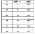
ステップS7において、機構制御部53は、濃度検出実施の信号を受け取ると、記憶手段90に予め記憶してある図15に示す濃度検出パターン112を搬送ベルト12上に印刷し始める。濃度検出パターン112は、搬送方向下流側からブラックK、イエローY、マゼンタM、シアンCの順に3セット並んでおり、それぞれのセットは搬送方向下流側からDutyが20%、40%、60%、80%、100%に対応する。この実施形態では、後述するように、印刷濃度データから各Duty間の濃度値を近似的に求めるため、サンプル数が多い方が精度良く求められるため、Dutyの組合せを20%、40%、60%、80%、100%とした。なお、濃度検出に用いるパターンは本パターンに限るものではなく、カラーの並び順やDutyの組合せは、都合に応じて変えてもよい。そして、機構制御部53(第1のサンプリング実行部534、第2のサンプリング実行部535)により、濃度検出パターン112の各ブロックについてステップS3と同様の処理によりサンプリングする。
In step S <b> 7, upon receiving a density detection execution signal, the
[ステップS8の処理について]
次に、階調補正制御部80が行う、ステップS8の処理の詳細について説明する。
[About Step S8]
Next, details of the process of step S8 performed by the gradation
以下では、ステップS8の処理について、図26〜図29に示す具体例を用いて詳細に説明する。画像処理部51の一部に設けられた階調補正制御部80は、前記機構制御部53が読み取った印刷濃度データを受け取る。この実施形態では、濃度検出パターン112として、ブラックK、イエローY、マゼンタM、シアンCのそれぞれにおいてDutyが20%、40%、60%、80%、100%の5種類を用いている。ここで、各Dutyを0〜255までの256階調レベルで表現すると、20%は51階調レベル、40%は102階調レベル、60%は153階調レベル、80%は204階調レベル、100%は255階調レベルとなる。階調補正制御部80は、受け取った印刷濃度データから、近似的に256階調レベル分の濃度値を計算する。
Below, the process of step S8 is demonstrated in detail using the specific example shown in FIGS. A gradation
また、記憶手段81には、階調レベルごとの濃度値をテーブル形式で格納するものである標準ターゲット階調特性テーブル87が記憶されている。図27は標準ターゲット階調特性テーブル87を示す図であり、標準ターゲット階調特性テーブル87のテーブル値は、理想的な連続階調が再現できるよう実験的にもしくはシミュレーションで求めたものである。
The
次に、階調補正制御部80は、印刷濃度特性と標準ターゲット階調特性を比較する。このとき、印刷濃度特性と標準ターゲット階調特性が一致していれば、理想的な連続階調が再現できるが、実際は、図28に示すように印刷濃度特性と標準ターゲット階調特性には、ズレが生じる場合がある。例えば、階調レベル51の印刷濃度特性と標準ターゲット階調特性それぞれの濃度値は、印刷濃度特性は0.33、標準ターゲット階調特性は0.30となっている。印刷濃度特性の濃度値0.33は標準ターゲット階調特性の階調レベル60に対応する。ここで、階調補正制御部80は、記憶手段81に記憶されている階調補正値テーブル84の入力階調レベル51の出力階調レベルを60と更新する。図29に示す階調補正値テーブル84は、入力階調レベルを出力階調レベルに変換するためのテーブルである。また、階調レベル102の印刷濃度特性と標準ターゲット階調特性それぞれの濃度値は、印刷濃度特性は0.65、標準ターゲット階調特性は0.60となっており、印刷濃度特性の濃度値0.65は標準ターゲット階調特性の階調レベル115に対応するので、階調補正値テーブル84の入力階調レベル102の出力階調レベルを115と記憶させる。同様にして、256階調レベルすべてにおいて、入力階調レベルと出力階調レベルを合わせ、更新された階調レベルの対応関係を階調補正値テーブル84に記憶させる。このような階調補正値テーブル84があれば、画像データとして出力階調レベルを或る値としたときに必要な入力階調レベルが分かり、その入力階調レベルの信号で画像処理を実行すると、最終的には対応した出力階調レベルの印刷結果が得られることになる。
Next, the gradation
通常モードの濃度補正処理では、以上のような一連の処理により画像形成装置1のエンジン部の物理特性(現像電圧、LED露光時間等)の調節とコマンド及び画像処理部51の階調補正制御部80で階調補正することで、出力される印刷の印刷濃度を安定させている。
In the density correction process in the normal mode, the adjustment of physical characteristics (developing voltage, LED exposure time, etc.) of the engine unit of the
(A−3)実施形態の効果
この実施形態によれば、以下のような効果を奏することができる。
(A-3) Effects of Embodiment According to this embodiment, the following effects can be achieved.
画像形成装置1では、第1のサンプリング実行部534によりブラックKに係る濃度補正に用いるサンプルを取得している。第1のサンプリング実行部534では、必要有効サンプル数N1に、最低追加サンプル数N2以上の追加サンプル数N3を加えた取得サンプル数N4の分サンプルを取得し、その中から濃度補正に有効なサンプルを選択している。これにより、画像形成装置1では、搬送ベルト12の一部に反射特性の異なる特定領域A1が形成されていたとしても、濃度補正処理の精度低下を抑制することができる。
In the
また、画像形成装置1では、第1のキャリブレーション実行部532を用いて、ブラックKに係るキャリブレーション制御処理を行っている。第1のキャリブレーション実行部532では、搬送ベルト12の一部に形成された反射特性の異なる特定領域A1の幅W1より大きい幅W2間隔で複数回サンプルを取得して、キャリブレーションに有効なサンプルを選択している。これにより、画像形成装置1では、搬送ベルト12の一部に反射特性の異なる特定領域A1が形成されていたとしても、キャリブレーション制御処理の精度低下を抑制することができる。
In the
(B)他の実施形態
本発明は、上記の実施形態に限定されるものではなく、以下に例示するような変形実施形態も挙げることができる。
(B) Other Embodiments The present invention is not limited to the above-described embodiments, and may include modified embodiments as exemplified below.
(B−1)上記の実施形態では、本発明の画像形成装置をプリンタに適用した例について説明したが、本発明の画像形成装置は、ファクシミリ通信機能や、スキャナー機能などを備えた複合機等の他の画像形成装置に適用するようにしてもよい。 (B-1) In the above-described embodiment, the example in which the image forming apparatus of the present invention is applied to a printer has been described. However, the image forming apparatus of the present invention is a multifunction machine having a facsimile communication function, a scanner function, or the like. The present invention may be applied to other image forming apparatuses.
(B−2)上記の実施形態の画像形成装置は、ブラックK及びカラー色(CMY)のトナーに対応していたが、ブラックKのみに対応したモノクロプリンタとして構成してもよい。その場合、当該画像形成装置には、拡散反射光受光用フォトトランジスタ103、第2のキャリブレーション実行部533、第2のサンプリング実行部535、濃度検出パターンにおけるカラー色のブロック等、カラー色(CMY)に係る処理に必要な構成要素は省略される。
(B-2) The image forming apparatus according to the above embodiment is compatible with black K and color (CMY) toner, but may be configured as a monochrome printer compatible with black K only. In this case, the image forming apparatus includes a color color (CMY) such as a diffuse reflected
1…画像形成装置、11…筐体、12…搬送ベルト、13…駆動ローラ、14…従動ローラ、15…吸着ローラ、16…ホッピングローラ、17…レジストローラ、18…ピンチローラ、19…用紙収容カセット、21〜23…センサ、24…濃度センサ、24a…シャッター、25…ヒートローラ、26…加圧ローラ、27…排出センサ、28…サーミスタ、29…ガイド、30…スタッカ、31…クリーニングブレード、32…廃トナータンク、50…ホストインタフェース部、51…コマンド及び画像処理部、52…LEDヘッドインタフェース部、53…機構制御部、531…濃度補正実行判定部、532…第1のキャリブレーション実行部、533…第2のキャリブレーション実行部、534…第1のサンプリング実行部、535…第2のサンプリング実行部、54…ホッピングモータ、55…レジストモータ、56…ベルトモータ、57…ヒータモータ、58…ドラムモータ、59…ヒータ、60…高圧制御部、61…CH発生部、62…DB発生部、63…TR発生部、80…階調補正制御部、81…記憶手段、90…記憶手段、201〜204…印刷機構、301〜304…LEDヘッド、401〜404…転写ローラ、501〜504…帯電ローラ、601〜604…感光ドラム、701〜704…現像ローラ、801〜804…現像ブレード、901〜904…スポンジローラ、1001〜1004…トナーカートリッジ、1101〜1104…除電光源。
DESCRIPTION OF
Claims (11)
前記画像形成ユニットを用いて、前記搬送ベルトの表面に、画像形成の濃度補正に係る検査用画像を形成する検査用画像形成手段と、
前記搬送ベルト上に形成された検査用画像に検査光を照射する検査用光源と、
前記検査用光源により照射され、検査用画像の領域で反射された反射光を受光して受光強度を測定する受光手段と、
前記駆動部及び前記検査用光源を制御して、検査用画像の領域上を第1の間隔おきに前記検査用光源に照射させて前記受光手段での受光強度を取得するものであって、少なくとも前記第1の間隔、及び前記特定領域の前記所定の幅に基づいて定まる第1の回数分受光強度を取得する受光強度取得制御手段と、
前記受光強度取得制御手段により取得された複数の受光強度のうち、前記画像形成ユニットに係る濃度補正制御に有効な受光強度を、所定数選択する選択手段と、
前記選択手段が選択した受光強度を用いて、それぞれの前記画像形成ユニットに係る濃度補正制御を行う濃度補正制御手段と
を有することを特徴とする画像形成装置。 An image forming unit that forms a developer image on a medium using one or a plurality of image forming units, and the medium is transported in the image forming unit, and is compared with other regions with a predetermined width in the medium transport direction. In an image forming apparatus comprising: an endless conveyance belt in which specific regions having different light reflection characteristics are formed; and a drive unit that drives the conveyance belt.
Inspection image forming means for forming an image for inspection relating to density correction for image formation on the surface of the transport belt using the image forming unit;
An inspection light source for irradiating inspection light to the inspection image formed on the conveyor belt;
A light receiving means for receiving the reflected light irradiated by the inspection light source and reflected by the region of the inspection image and measuring the received light intensity;
Controlling the driving unit and the inspection light source to irradiate the inspection light source on a region of the inspection image at a first interval to obtain the light reception intensity at the light receiving means; Received light intensity acquisition control means for acquiring received light intensity for a first number of times determined based on the first interval and the predetermined width of the specific area;
A selection unit that selects a predetermined number of received light intensity effective for density correction control related to the image forming unit among the plurality of received light intensity acquired by the received light intensity acquisition control unit;
An image forming apparatus comprising: density correction control means for performing density correction control for each of the image forming units using the received light intensity selected by the selection means.
前記検査用画像形成手段は、前記第1の画像形成ユニット及び前記第2の画像形成ユニットのそれぞれを制御して、前記搬送ベルトの表面に検査用画像を形成させ、
前記受光手段は、前記第1の色の現像剤により形成された第1の検査用画像の反射光を受光する第1の受光部と、前記第2の色の現像剤により形成された第2の検査用画像の反射光を受光する第2の受光部とを有し、
前記受光強度取得制御手段は、前記第1の検査用画像について、前記第1の回数受光強度を取得し、前記第2の検査用画像については前記第1の検査用画像とは異なる第2の回数受光強度を取得する
ことを特徴とする請求項1に記載の画像形成装置。 The image forming unit includes a first image forming unit that forms an image using a first color developer and a second image forming unit that forms an image using a second color developer. ,
The inspection image forming means controls each of the first image forming unit and the second image forming unit to form an inspection image on the surface of the transport belt,
The light receiving means includes a first light receiving portion for receiving reflected light of a first inspection image formed by the first color developer, and a second light formed by the second color developer. A second light receiving unit that receives the reflected light of the inspection image of
The received light intensity acquisition control means acquires the first received light intensity for the first inspection image, and the second inspection image is a second different from the first inspection image. The image forming apparatus according to claim 1, wherein the number of times received light intensity is acquired.
前記画像形成ユニットを用いて、前記搬送ベルトの表面に、画像形成の濃度補正に係る検査用画像を形成する検査用画像形成工程と、
前記検査用光源により、前記搬送ベルト上に形成された検査用画像に検査光を照射する検査光照射工程と、
前記受光手段により、前記検査用光源により照射され、検査用画像の領域で反射された反射光を受光して受光強度を測定する受光工程と、
前記駆動部及び前記検査用光源を制御して、検査用画像の領域上を第1の間隔おきに前記検査用光源に照射させて前記受光手段での受光強度を取得するものであって、少なくとも前記第1の間隔、及び前記特定領域の前記所定の幅に基づいて定まる第1の回数受光強度を取得する受光強度取得制御工程と、
前記受光強度取得制御工程により取得された複数の受光強度のうち、前記画像形成ユニットに係る濃度補正制御に有効な受光強度を、所定数選択する選択工程と、
前記選択工程で選択された受光強度を用いて、前記画像形成ユニットに係る濃度補正制御を行う濃度補正制御工程と
を含むことを特徴とする画像形成装置の制御方法。 An image forming unit that forms a developer image on a medium using one or a plurality of image forming units, and the medium is transported in the image forming unit, and is compared with other regions with a predetermined width in the medium transport direction. In an image forming apparatus control method comprising: an endless transport belt in which specific regions having different light reflection characteristics are formed; a drive unit that drives the transport belt; a light source for inspection; and a light receiving unit.
An image forming process for inspection that forms an image for inspection related to density correction for image formation on the surface of the transport belt using the image forming unit;
An inspection light irradiation step of irradiating inspection light on the inspection image formed on the conveyor belt with the inspection light source;
A light receiving step of receiving the reflected light that is irradiated by the light source for inspection and reflected by the region of the image for inspection by the light receiving means, and measuring the received light intensity;
Controlling the driving unit and the inspection light source to irradiate the inspection light source on a region of the inspection image at a first interval to obtain the light reception intensity at the light receiving means; A received light intensity acquisition control step of acquiring a first received light intensity determined based on the first interval and the predetermined width of the specific region;
A selection step of selecting a predetermined number of light reception intensities effective for density correction control related to the image forming unit among the plurality of light reception intensities acquired by the light reception intensity acquisition control step;
And a density correction control step of performing density correction control related to the image forming unit using the received light intensity selected in the selection step.
前記媒体が搬送される方向に走行するものであって、第1の幅の継目が形成されたベルトと、
前記媒体上に置かれる黒色の現像剤の現像剤像を形成するものであって、前記ベルトに黒色の現像剤で濃度検出パターンを形成することが可能な画像形成部と、
前記濃度検出パターンが形成される領域に光を照射する発光センサと、
前記照射された光の反射光を検知する受光センサと、
前記受光センサの検知結果に基づいて前記画像形成部の補正処理を行う補正部と、
前記発光センサに対して、前記濃度検出パターンが形成される領域に第2の幅ごとに第1の回数光を照射させるように制御し、前記受光センサの検知結果のうち第2の回数分の検知結果を選択し、前記補正部に対して選択した検知結果に基づいて前記画像形成部の補正処理を実行するように制御する制御部とを有し、
前記第1の回数は、前記第2の回数と、前記第1の幅を前記第2の幅で除算して小数点以下を切り捨てて1加算した第3の回数とを加算した回数である
ことを特徴とする画像形成装置。 In an image forming apparatus that forms an image on a medium,
A belt that travels in a direction in which the medium is conveyed, and formed with a first width seam;
An image forming unit for forming a developer image of a black developer placed on the medium, and capable of forming a density detection pattern with the black developer on the belt;
A light emitting sensor for irradiating light to a region where the density detection pattern is formed;
A light receiving sensor for detecting reflected light of the irradiated light;
A correction unit that performs correction processing of the image forming unit based on a detection result of the light receiving sensor;
The light emitting sensor is controlled to irradiate the region where the density detection pattern is formed with the first number of times for each second width, and the second number of times of the detection results of the light receiving sensor. A control unit that selects a detection result and controls the image forming unit to perform correction processing based on the selected detection result for the correction unit;
The first number, the second number of times, that the number of times said first width obtained by adding the third number of which is 1 adds the decimal is divided by the second width An image forming apparatus.
Priority Applications (2)
| Application Number | Priority Date | Filing Date | Title |
|---|---|---|---|
| JP2013094237A JP5894962B2 (en) | 2013-04-26 | 2013-04-26 | Image forming apparatus and method of controlling image forming apparatus |
| US14/260,921 US9001377B2 (en) | 2013-04-26 | 2014-04-24 | Image forming apparatus and method of controlling the image forming apparatus |
Applications Claiming Priority (1)
| Application Number | Priority Date | Filing Date | Title |
|---|---|---|---|
| JP2013094237A JP5894962B2 (en) | 2013-04-26 | 2013-04-26 | Image forming apparatus and method of controlling image forming apparatus |
Publications (3)
| Publication Number | Publication Date |
|---|---|
| JP2014215533A JP2014215533A (en) | 2014-11-17 |
| JP2014215533A5 JP2014215533A5 (en) | 2015-04-09 |
| JP5894962B2 true JP5894962B2 (en) | 2016-03-30 |
Family
ID=51789048
Family Applications (1)
| Application Number | Title | Priority Date | Filing Date |
|---|---|---|---|
| JP2013094237A Expired - Fee Related JP5894962B2 (en) | 2013-04-26 | 2013-04-26 | Image forming apparatus and method of controlling image forming apparatus |
Country Status (2)
| Country | Link |
|---|---|
| US (1) | US9001377B2 (en) |
| JP (1) | JP5894962B2 (en) |
Families Citing this family (6)
| Publication number | Priority date | Publication date | Assignee | Title |
|---|---|---|---|---|
| KR20150063652A (en) * | 2013-12-02 | 2015-06-10 | 삼성전자주식회사 | Image forming apparatus, method for calibration of print density and and computer-readable recording medium |
| JP2016144872A (en) * | 2015-02-06 | 2016-08-12 | 富士ゼロックス株式会社 | Image forming device |
| JP6623624B2 (en) * | 2015-09-01 | 2019-12-25 | セイコーエプソン株式会社 | Media texture detection device |
| JP6776884B2 (en) * | 2016-12-26 | 2020-10-28 | コニカミノルタ株式会社 | Controller, calibration control program and calibration control method |
| JP6877230B2 (en) * | 2017-04-27 | 2021-05-26 | 株式会社沖データ | Image forming device and inspection method |
| CN112050948B (en) * | 2020-08-05 | 2021-12-03 | 沈阳上博智像科技有限公司 | Non-barrier infrared temperature measurement method based on detector temperature drift model |
Family Cites Families (12)
| Publication number | Priority date | Publication date | Assignee | Title |
|---|---|---|---|---|
| JP2534706B2 (en) * | 1987-05-12 | 1996-09-18 | 株式会社リコー | Image forming device |
| JP2003098793A (en) * | 2001-09-25 | 2003-04-04 | Ricoh Co Ltd | Color alignment control system for image forming apparatus |
| JP2003122082A (en) * | 2001-10-09 | 2003-04-25 | Canon Inc | Image forming apparatus |
| JP2006003816A (en) * | 2004-06-21 | 2006-01-05 | Sharp Corp | Image forming apparatus and density corrected data producing method used for the same |
| JP2006091736A (en) | 2004-09-27 | 2006-04-06 | Oki Data Corp | Image correcting method and image forming apparatus |
| JP4757136B2 (en) * | 2005-08-31 | 2011-08-24 | キヤノン株式会社 | Recording apparatus and control method |
| JP5294617B2 (en) * | 2007-12-05 | 2013-09-18 | キヤノン株式会社 | Image forming apparatus |
| JP2010276854A (en) * | 2009-05-28 | 2010-12-09 | Sharp Corp | Image forming apparatus |
| JP4981853B2 (en) * | 2009-07-01 | 2012-07-25 | 株式会社沖データ | Image forming apparatus and color balance adjusting method |
| JP5344601B2 (en) * | 2009-07-01 | 2013-11-20 | キヤノン株式会社 | Image forming apparatus and method of controlling image forming apparatus |
| JP5128550B2 (en) * | 2009-07-06 | 2013-01-23 | 株式会社沖データ | Image forming apparatus |
| JP5929011B2 (en) * | 2011-05-23 | 2016-06-01 | ブラザー工業株式会社 | Image forming apparatus |
-
2013
- 2013-04-26 JP JP2013094237A patent/JP5894962B2/en not_active Expired - Fee Related
-
2014
- 2014-04-24 US US14/260,921 patent/US9001377B2/en not_active Expired - Fee Related
Also Published As
| Publication number | Publication date |
|---|---|
| US20140320916A1 (en) | 2014-10-30 |
| US9001377B2 (en) | 2015-04-07 |
| JP2014215533A (en) | 2014-11-17 |
Similar Documents
| Publication | Publication Date | Title |
|---|---|---|
| JP5894962B2 (en) | Image forming apparatus and method of controlling image forming apparatus | |
| JP2009217163A (en) | Image forming apparatus and image forming method | |
| JP2008096478A (en) | Image forming apparatus | |
| US7471908B2 (en) | Image forming apparatus that forms adjustment images having different densities and image forming method of controlling the image forming apparatus | |
| JP4890810B2 (en) | Image forming apparatus | |
| JP4681993B2 (en) | Image forming apparatus | |
| JP4883112B2 (en) | Image forming apparatus | |
| US7865095B2 (en) | Image forming apparatus including distance detection unit | |
| JP4347208B2 (en) | Image forming apparatus and control value setting method thereof | |
| JP6877230B2 (en) | Image forming device and inspection method | |
| US8537414B2 (en) | Image forming apparatus and method of adjusting color balance | |
| JP2004279664A (en) | Color image forming apparatus and toner sticking amount calculating method | |
| JP2007148259A (en) | Image forming apparatus | |
| JP2015166846A (en) | Control apparatus which determines exposure energy to be used for image formation, and image forming apparatus using the same | |
| US10527995B1 (en) | Image forming apparatus having abnormality detection unit for humidity sensor | |
| JP2005300918A (en) | Image forming apparatus | |
| JP4343079B2 (en) | Image forming apparatus | |
| JP2017003715A (en) | Image forming apparatus | |
| JP3804354B2 (en) | Image density detector | |
| US11513461B2 (en) | Image forming apparatus and image quality adjustment method | |
| JP2018141853A (en) | Image formation device | |
| JP6992646B2 (en) | Image forming device and density gradation correction method | |
| JP6665796B2 (en) | Integrated sensor and image forming apparatus having the same | |
| JP6264281B2 (en) | Image forming apparatus | |
| JP6049995B2 (en) | Image forming apparatus |
Legal Events
| Date | Code | Title | Description |
|---|---|---|---|
| A521 | Written amendment |
Free format text: JAPANESE INTERMEDIATE CODE: A523 Effective date: 20150223 |
|
| A621 | Written request for application examination |
Free format text: JAPANESE INTERMEDIATE CODE: A621 Effective date: 20150223 |
|
| RD02 | Notification of acceptance of power of attorney |
Free format text: JAPANESE INTERMEDIATE CODE: A7422 Effective date: 20150223 |
|
| A131 | Notification of reasons for refusal |
Free format text: JAPANESE INTERMEDIATE CODE: A131 Effective date: 20150728 |
|
| A977 | Report on retrieval |
Free format text: JAPANESE INTERMEDIATE CODE: A971007 Effective date: 20150729 |
|
| A521 | Written amendment |
Free format text: JAPANESE INTERMEDIATE CODE: A523 Effective date: 20150928 |
|
| A131 | Notification of reasons for refusal |
Free format text: JAPANESE INTERMEDIATE CODE: A131 Effective date: 20151110 |
|
| A521 | Written amendment |
Free format text: JAPANESE INTERMEDIATE CODE: A523 Effective date: 20160108 |
|
| TRDD | Decision of grant or rejection written | ||
| A01 | Written decision to grant a patent or to grant a registration (utility model) |
Free format text: JAPANESE INTERMEDIATE CODE: A01 Effective date: 20160209 |
|
| A61 | First payment of annual fees (during grant procedure) |
Free format text: JAPANESE INTERMEDIATE CODE: A61 Effective date: 20160229 |
|
| R150 | Certificate of patent or registration of utility model |
Ref document number: 5894962 Country of ref document: JP Free format text: JAPANESE INTERMEDIATE CODE: R150 |
|
| LAPS | Cancellation because of no payment of annual fees |