JP5894598B2 - Method and apparatus for producing fibers, in particular for producing fiber-containing nonwovens - Google Patents
Method and apparatus for producing fibers, in particular for producing fiber-containing nonwovens Download PDFInfo
- Publication number
- JP5894598B2 JP5894598B2 JP2013523608A JP2013523608A JP5894598B2 JP 5894598 B2 JP5894598 B2 JP 5894598B2 JP 2013523608 A JP2013523608 A JP 2013523608A JP 2013523608 A JP2013523608 A JP 2013523608A JP 5894598 B2 JP5894598 B2 JP 5894598B2
- Authority
- JP
- Japan
- Prior art keywords
- meltblown
- die head
- filament
- fibers
- fiber
- Prior art date
- Legal status (The legal status is an assumption and is not a legal conclusion. Google has not performed a legal analysis and makes no representation as to the accuracy of the status listed.)
- Expired - Fee Related
Links
Images


Classifications
-
- D—TEXTILES; PAPER
- D01—NATURAL OR MAN-MADE THREADS OR FIBRES; SPINNING
- D01D—MECHANICAL METHODS OR APPARATUS IN THE MANUFACTURE OF ARTIFICIAL FILAMENTS, THREADS, FIBRES, BRISTLES OR RIBBONS
- D01D5/00—Formation of filaments, threads, or the like
- D01D5/08—Melt spinning methods
- D01D5/098—Melt spinning methods with simultaneous stretching
- D01D5/0985—Melt spinning methods with simultaneous stretching by means of a flowing gas (e.g. melt-blowing)
-
- D—TEXTILES; PAPER
- D01—NATURAL OR MAN-MADE THREADS OR FIBRES; SPINNING
- D01D—MECHANICAL METHODS OR APPARATUS IN THE MANUFACTURE OF ARTIFICIAL FILAMENTS, THREADS, FIBRES, BRISTLES OR RIBBONS
- D01D4/00—Spinnerette packs; Cleaning thereof
- D01D4/02—Spinnerettes
-
- D—TEXTILES; PAPER
- D01—NATURAL OR MAN-MADE THREADS OR FIBRES; SPINNING
- D01D—MECHANICAL METHODS OR APPARATUS IN THE MANUFACTURE OF ARTIFICIAL FILAMENTS, THREADS, FIBRES, BRISTLES OR RIBBONS
- D01D4/00—Spinnerette packs; Cleaning thereof
- D01D4/02—Spinnerettes
- D01D4/025—Melt-blowing or solution-blowing dies
-
- D—TEXTILES; PAPER
- D01—NATURAL OR MAN-MADE THREADS OR FIBRES; SPINNING
- D01D—MECHANICAL METHODS OR APPARATUS IN THE MANUFACTURE OF ARTIFICIAL FILAMENTS, THREADS, FIBRES, BRISTLES OR RIBBONS
- D01D5/00—Formation of filaments, threads, or the like
- D01D5/08—Melt spinning methods
- D01D5/088—Cooling filaments, threads or the like, leaving the spinnerettes
- D01D5/092—Cooling filaments, threads or the like, leaving the spinnerettes in shafts or chimneys
-
- D—TEXTILES; PAPER
- D01—NATURAL OR MAN-MADE THREADS OR FIBRES; SPINNING
- D01D—MECHANICAL METHODS OR APPARATUS IN THE MANUFACTURE OF ARTIFICIAL FILAMENTS, THREADS, FIBRES, BRISTLES OR RIBBONS
- D01D5/00—Formation of filaments, threads, or the like
- D01D5/08—Melt spinning methods
- D01D5/098—Melt spinning methods with simultaneous stretching
-
- D—TEXTILES; PAPER
- D01—NATURAL OR MAN-MADE THREADS OR FIBRES; SPINNING
- D01D—MECHANICAL METHODS OR APPARATUS IN THE MANUFACTURE OF ARTIFICIAL FILAMENTS, THREADS, FIBRES, BRISTLES OR RIBBONS
- D01D5/00—Formation of filaments, threads, or the like
- D01D5/12—Stretch-spinning methods
- D01D5/14—Stretch-spinning methods with flowing liquid or gaseous stretching media, e.g. solution-blowing
-
- D—TEXTILES; PAPER
- D01—NATURAL OR MAN-MADE THREADS OR FIBRES; SPINNING
- D01D—MECHANICAL METHODS OR APPARATUS IN THE MANUFACTURE OF ARTIFICIAL FILAMENTS, THREADS, FIBRES, BRISTLES OR RIBBONS
- D01D5/00—Formation of filaments, threads, or the like
- D01D5/253—Formation of filaments, threads, or the like with a non-circular cross section; Spinnerette packs therefor
-
- D—TEXTILES; PAPER
- D04—BRAIDING; LACE-MAKING; KNITTING; TRIMMINGS; NON-WOVEN FABRICS
- D04H—MAKING TEXTILE FABRICS, e.g. FROM FIBRES OR FILAMENTARY MATERIAL; FABRICS MADE BY SUCH PROCESSES OR APPARATUS, e.g. FELTS, NON-WOVEN FABRICS; COTTON-WOOL; WADDING ; NON-WOVEN FABRICS FROM STAPLE FIBRES, FILAMENTS OR YARNS, BONDED WITH AT LEAST ONE WEB-LIKE MATERIAL DURING THEIR CONSOLIDATION
- D04H1/00—Non-woven fabrics formed wholly or mainly of staple fibres or like relatively short fibres
- D04H1/40—Non-woven fabrics formed wholly or mainly of staple fibres or like relatively short fibres from fleeces or layers composed of fibres without existing or potential cohesive properties
- D04H1/42—Non-woven fabrics formed wholly or mainly of staple fibres or like relatively short fibres from fleeces or layers composed of fibres without existing or potential cohesive properties characterised by the use of certain kinds of fibres insofar as this use has no preponderant influence on the consolidation of the fleece
- D04H1/4391—Non-woven fabrics formed wholly or mainly of staple fibres or like relatively short fibres from fleeces or layers composed of fibres without existing or potential cohesive properties characterised by the use of certain kinds of fibres insofar as this use has no preponderant influence on the consolidation of the fleece characterised by the shape of the fibres
-
- D—TEXTILES; PAPER
- D04—BRAIDING; LACE-MAKING; KNITTING; TRIMMINGS; NON-WOVEN FABRICS
- D04H—MAKING TEXTILE FABRICS, e.g. FROM FIBRES OR FILAMENTARY MATERIAL; FABRICS MADE BY SUCH PROCESSES OR APPARATUS, e.g. FELTS, NON-WOVEN FABRICS; COTTON-WOOL; WADDING ; NON-WOVEN FABRICS FROM STAPLE FIBRES, FILAMENTS OR YARNS, BONDED WITH AT LEAST ONE WEB-LIKE MATERIAL DURING THEIR CONSOLIDATION
- D04H1/00—Non-woven fabrics formed wholly or mainly of staple fibres or like relatively short fibres
- D04H1/40—Non-woven fabrics formed wholly or mainly of staple fibres or like relatively short fibres from fleeces or layers composed of fibres without existing or potential cohesive properties
- D04H1/54—Non-woven fabrics formed wholly or mainly of staple fibres or like relatively short fibres from fleeces or layers composed of fibres without existing or potential cohesive properties by welding together the fibres, e.g. by partially melting or dissolving
- D04H1/56—Non-woven fabrics formed wholly or mainly of staple fibres or like relatively short fibres from fleeces or layers composed of fibres without existing or potential cohesive properties by welding together the fibres, e.g. by partially melting or dissolving in association with fibre formation, e.g. immediately following extrusion of staple fibres
-
- D—TEXTILES; PAPER
- D04—BRAIDING; LACE-MAKING; KNITTING; TRIMMINGS; NON-WOVEN FABRICS
- D04H—MAKING TEXTILE FABRICS, e.g. FROM FIBRES OR FILAMENTARY MATERIAL; FABRICS MADE BY SUCH PROCESSES OR APPARATUS, e.g. FELTS, NON-WOVEN FABRICS; COTTON-WOOL; WADDING ; NON-WOVEN FABRICS FROM STAPLE FIBRES, FILAMENTS OR YARNS, BONDED WITH AT LEAST ONE WEB-LIKE MATERIAL DURING THEIR CONSOLIDATION
- D04H3/00—Non-woven fabrics formed wholly or mainly of yarns or like filamentary material of substantial length
- D04H3/02—Non-woven fabrics formed wholly or mainly of yarns or like filamentary material of substantial length characterised by the method of forming fleeces or layers, e.g. reorientation of yarns or filaments
- D04H3/03—Non-woven fabrics formed wholly or mainly of yarns or like filamentary material of substantial length characterised by the method of forming fleeces or layers, e.g. reorientation of yarns or filaments at random
-
- Y—GENERAL TAGGING OF NEW TECHNOLOGICAL DEVELOPMENTS; GENERAL TAGGING OF CROSS-SECTIONAL TECHNOLOGIES SPANNING OVER SEVERAL SECTIONS OF THE IPC; TECHNICAL SUBJECTS COVERED BY FORMER USPC CROSS-REFERENCE ART COLLECTIONS [XRACs] AND DIGESTS
- Y10—TECHNICAL SUBJECTS COVERED BY FORMER USPC
- Y10T—TECHNICAL SUBJECTS COVERED BY FORMER US CLASSIFICATION
- Y10T442/00—Fabric [woven, knitted, or nonwoven textile or cloth, etc.]
- Y10T442/60—Nonwoven fabric [i.e., nonwoven strand or fiber material]
- Y10T442/608—Including strand or fiber material which is of specific structural definition
- Y10T442/609—Cross-sectional configuration of strand or fiber material is specified
- Y10T442/611—Cross-sectional configuration of strand or fiber material is other than circular
Description
本発明は、繊維紡糸の分野に関する。この分野において、本発明は、主に繊維を紡糸するための新規な改善された方法及び装置、及び繊維含有不織布、特にパルプ含有メルトブローン不織布を製造するための新規な方法及び装置に関する。 The present invention relates to the field of fiber spinning. In this field, the present invention relates primarily to a new and improved method and apparatus for spinning fibers, and a new method and apparatus for producing fiber-containing nonwovens, particularly pulp-containing meltblown nonwovens.
繊維を紡糸し、不織布を作るための周知の技術は、いわゆるメルトブロー技術である。メルトブローン不織布を製造するための方法及び装置は周知であり、例えばButinらの米国特許第3849241号、及びHardingらの米国特許第4048364号に記載されている。 A well-known technique for spinning fibers and making nonwovens is the so-called meltblowing technique. Methods and apparatus for producing meltblown nonwovens are well known and are described, for example, in Butin et al. US Pat. No. 3,849,241 and Harding et al. US Pat. No. 4,048,364.
基本的に、メルトブローン不織布を製造するための周知の方法は、溶融ポリマー材料をダイヘッドを通してメルトブローンポリマーフィラメントに押出すこと、及び高速度加熱ガス(通常、空気)の収斂流(以後「一次空気」と呼ばれる)によりこれらのフィラメントを細繊化することを含む。この一次熱空気は、典型的にはポリマーの溶融温度に等しいかまたはそれよりわずかに高い温度に加熱される。この一次熱空気は、ダイヘッドの出口でポリマーフィラメントを直接引張りかつ細繊化する。従って、メルトブロー法では、メルトブローンフィラメントを細繊化するための引張り力は、ポリマーがまだ溶融状態にある間にダイヘッドの出口で直接付与される。ダイヘッドの出口で、大容積の冷却空気(以後「二次空気」と呼ばれる)が一次空気中に引張られる。この二次空気は、ダイヘッドから下流のメルトブローンフィラメントを冷却し、かつメルトブローンフィラメントの急冷を提供する。 Basically, well-known methods for producing meltblown nonwovens include extruding molten polymer material through a die head into a meltblown polymer filament and a converging flow of high-speed heated gas (usually air) (hereinafter “primary air”). And so on) to refine these filaments. This primary hot air is typically heated to a temperature equal to or slightly above the melting temperature of the polymer. This primary hot air pulls and fines the polymer filaments directly at the exit of the die head. Thus, in the meltblowing process, the tensile force to fine the meltblown filament is applied directly at the die head exit while the polymer is still in the molten state. At the exit of the die head, a large volume of cooling air (hereinafter referred to as “secondary air”) is pulled into the primary air. This secondary air cools the meltblown filament downstream from the die head and provides quenching of the meltblown filament.
一般的に、メルトブロー法では、一次空気はまた、メルトブローンフィラメントがダイヘッドの出口で短い長さの不連続繊維(マイクロ繊維またはナノ繊維)に破断されるような方法で調整される。不連続繊維は、一般的にステープル繊維の典型的な長さを越える長さを持つ。特に、現在まで標準的な既知のメルトブロー法により、5mm〜20mmの長さを持つ不連続メルトブローン繊維が製造されることができる。 In general, in the meltblowing process, the primary air is also conditioned in such a way that the meltblown filaments are broken into short lengths of discontinuous fibers (microfibers or nanofibers) at the die head exit. The discontinuous fibers generally have a length that exceeds the typical length of staple fibers. In particular, discontinuous meltblown fibers having a length of 5 mm to 20 mm can be produced by standard known meltblowing methods to date.
メルトブローン繊維は、非配向メルトブローン繊維のメルトブローン不織布ウエブを形成するために、例えばシリンダーまたはコンベアベルトのような移動表面上にダイヘッドから下流に送出される。好ましくは、形成表面は通気性であり、さらにより好ましくは形成表面上に繊維を吸い込むために吸引手段が設けられる。このメルトブローン不織布ウエブは次いで、固められたメルトブローン不織布ウエブを形成するために、例えば熱結合カレンダー、水ニードリング装置、超音波結合装置のような固めるための手段に輸送されることができる。 The meltblown fibers are delivered downstream from the die head onto a moving surface, such as a cylinder or conveyor belt, to form a meltblown nonwoven web of unoriented meltblown fibers. Preferably, the forming surface is breathable, and even more preferably suction means are provided for drawing fibers onto the forming surface. This meltblown nonwoven web can then be transported to a consolidation means such as, for example, a thermal bonding calendar, a water needling device, an ultrasonic bonding device, to form a consolidated meltblown nonwoven web.
標準的なメルトブロー法により、非常に細いデニールの繊維から作られたメルトブローン不織布が有利に製造されることができる。典型的には、メルトブローン繊維の平均直径は10μm未満であることができる。結果として、低通気性及び良好な被覆性のメルトブローン不織布が有利に得られることができる。 Standard meltblowing methods can advantageously produce meltblown nonwovens made from very fine denier fibers. Typically, the average diameter of the meltblown fibers can be less than 10 μm. As a result, a melt blown nonwoven fabric with low air permeability and good coverage can be advantageously obtained.
代わりに、メルトブローン技術は幾つかの制限と欠点を持つ。 Instead, meltblown technology has some limitations and drawbacks.
標準的なメルトブロー法時に、メルトブローン繊維は、小さな延伸にさらされているにすぎず、従ってメルトブローン繊維は低い靭性を示す。従って、メルトブローン不織布は、一般的に劣った機械的性質を持ち、特に機械方向及び横方向に低い靭性と低い機械的引張り強さを、かつ低い弾性を示す。 During standard meltblowing processes, meltblown fibers are only exposed to small stretches, and therefore meltblown fibers exhibit low toughness. Accordingly, meltblown nonwovens generally have inferior mechanical properties, particularly low toughness and low mechanical tensile strength in the machine and transverse directions, and low elasticity.
加えて、標準的メルトブロー法では、必要なメルトブローンフィラメントの細繊化並びにメルトブローンフィラメントの予め決められた平均長さの不連続メルトブローン繊維への適切な破断を達成するために、一次空気の速度が調整されなければならない。実際に、メルトブローンフィラメントの十分な細繊化を得るため、及び細いデニールのメルトブローン繊維を製造するために、一次空気の速度は十分に高くなければならず、それはまた、より短いメルトブローン繊維の製造に導く。従って、標準的なメルトブロー法では、メルトブローン繊維の平均直径及び長さの調整は困難であり、あまり融通がきかない。特に、典型的には10μm未満の非常に小さい直径を持ち、かつ例えば20mmより大きい長さを持つメルトブローンポリプロピレン繊維を作ることは難しい。 In addition, the standard meltblowing process adjusts the primary air velocity to achieve the required meltblown filament refinement and proper breakage of the meltblown filament into a predetermined average length of discontinuous meltblown fibers. It must be. In fact, in order to obtain sufficient fineness of the meltblown filaments and to produce thin denier meltblown fibers, the primary air velocity must be sufficiently high, which also makes it possible to produce shorter meltblown fibers. Lead. Therefore, it is difficult to adjust the average diameter and length of the meltblown fiber by the standard meltblowing method, and it is not very flexible. In particular, it is difficult to make meltblown polypropylene fibers that have a very small diameter, typically less than 10 μm, and have a length of, for example, greater than 20 mm.
現在まで、標準的なメルトブロー技術では、高いメルトフローインデックス(典型的には600〜2000)のポリマーのみが加工されることができる。たとえ非円形紡糸孔口、例えば二裂片形状をした孔口を持つ紡糸口金が使用されたとしても、フィラメントの延伸と組み合わせたこの高いメルトフローインデックスは、フィラメントの断面の変形に導き、紡糸孔口により与えられたフィラメント形状は維持されることができない。現実的には、断面が実質的に円形形状のみを持つメルトブローンフィラメントを実際に作ることができる。 To date, with standard meltblowing techniques, only high melt flow index (typically 600-2000) polymers can be processed. This high melt flow index combined with filament drawing leads to deformation of the filament cross-section, even if a non-circular spinneret, such as a spinneret with a two-piece shape, is used. The filament shape given by cannot be maintained. In practice, a meltblown filament having a substantially circular cross-section only can be actually made.
米国特許第5075068号では、フィラメントにうねりを作ることにより、それらの形状を分裂するためにメルトブローンフィラメントに向けて追加の交差流空気を放出することが提案されている。このうねりは、一次メルトブローン空気により与えられる抵抗力を強化するであろう。本発明者の知識では、かかる技術は未だに商業化されておらず、交差流空気によるフィラメントのうねりは、制御するのが困難であると思われ、かつフィラメントの有害なうねりを導くだろう。 U.S. Pat. No. 5,075,068 proposes releasing additional cross-flow air toward the meltblown filaments to disrupt their shape by creating undulations in the filaments. This swell will enhance the resistance provided by the primary meltblown air. To the inventor's knowledge, such techniques have not yet been commercialized and filament undulation by cross-flow air appears to be difficult to control and will lead to harmful undulations of the filament.
固められたメルトブローン不織布は、織物製品を作るために単独で使用されることができ、または例えば他の不織布ウエブ(単数または複数)[メルトブローンウエブ(単数または複数)、スパンボンデッドウエブ(単数または複数)、カード化されたウエブ(単数または複数)、エアレイドウエブ(単数または複数)]のような追加の層、及び/または例えば木材パルプ繊維から作られた繊維層(単数または複数)のような追加の繊維の層(単数または複数)、及び/または追加のプラスチックフィルム(単数または複数)を含むラミネートで使用されることができる。このラミネートは、熱結合、機械的結合、ハイドロエンタングリング、超音波結合、通気結合、及び接着剤結合を含む、いかなる既知の固め手段により固められることができる。 The consolidated meltblown nonwoven can be used alone to make a woven product or, for example, other nonwoven web (s) [meltblown web (s), spunbonded web (s) ), Additional layers such as carded web (s), airlaid web (s), and / or additional layers such as fiber layer (s) made from wood pulp fibers, for example. Can be used in laminates comprising a plurality of fiber layer (s) and / or additional plastic film (s). The laminate can be consolidated by any known consolidation means including thermal bonding, mechanical bonding, hydroentangling, ultrasonic bonding, vent bonding, and adhesive bonding.
より詳細には、高吸収性を持つラミネートを作るために、メルトブローン不織布を、例えば短い木材パルプ繊維の層のような高い吸収能力を持つ少なくとも一つの繊維材料層とラミネートすることが知られている。木材パルプ繊維のこの層はまた、超吸収材料から作られた粒子のような粒子と混合されることができる。 More specifically, it is known to laminate a meltblown nonwoven fabric with at least one fiber material layer having a high absorbent capacity, such as a layer of short wood pulp fibers, in order to make a laminate with high absorbency. . This layer of wood pulp fibers can also be mixed with particles such as particles made from superabsorbent material.
かかるラミネートの一つの重要な欠点は、ラミネートの固め工程の前または後であっても繊維層とメルトブローン不織布の間の低い結合力である。この低い結合力は繊維材料(例えば木材パルプ繊維)の高度かつ有害な損失に導く。 One important drawback of such laminates is the low bond strength between the fiber layer and the meltblown nonwoven fabric, either before or after the consolidation process of the laminate. This low bond strength leads to a high and harmful loss of fiber material (eg wood pulp fiber).
繊維含有メルトブローン不織布、特にパルプ含有メルトブローン不織布を製造するための方法はまた、従来技術で既知であり、例えばRadwanskiらの米国特許第4931355号及び米国特許第4939016号に開示されている。繊維材料、例えば木材パルプは、メルトブローダイヘッドの出口から直ぐ下流のポリマー流中に直接供給される。 Methods for producing fiber-containing meltblown nonwovens, particularly pulp-containing meltblown nonwovens, are also known in the prior art and are disclosed, for example, in Radwanski et al. US Pat. No. 4,931,355 and US Pat. No. 4,939,016. Fibrous material, such as wood pulp, is fed directly into the polymer stream immediately downstream from the outlet of the meltblowing die head.
かかる方法では、ダイヘッドの出口のポリマー流の高い速度のために、ダイヘッドを通して押出されるメルトブローンフィラメントの内側に繊維材料を信頼性をもって含めることは実際に困難である。結果として、製造工程時に、大量の繊維材料がメルトブローンフィラメントの内側に含められず、これに反してダイヘッドから下流でメルトブローンフィラメントを取り囲む空気流により押し戻される。さらに、かかる工程により得られる繊維含有メルトブローン不織布では、繊維材料はメルトブローン繊維と強く混じり合わず、メルトブローン繊維と繊維材料の結合は低い。この低い結合は、繊維含有メルトブローン不織布が続いて輸送されまたは取り扱われるときに繊維材料の高い損失に導く。繊維材料のこの損失は、前述の米国特許第4931355号及び米国特許第4939016号に記載されたような繊維含有メルトブローン不織布が続くハイドロエンタングルメント工程にゆだねられる場合により一層重要でありかつ有害となる。 In such a process, it is actually difficult to reliably include the fiber material inside the meltblown filament that is extruded through the die head due to the high velocity of the polymer stream at the outlet of the die head. As a result, during the manufacturing process, a large amount of fiber material is not included inside the meltblown filaments, but is pushed back by the air flow surrounding the meltblown filaments downstream from the die head. Furthermore, in the fiber-containing meltblown nonwoven fabric obtained by such a process, the fiber material does not mix strongly with the meltblown fiber, and the bond between the meltblown fiber and the fiber material is low. This low bond leads to a high loss of fiber material when the fiber-containing meltblown nonwoven is subsequently transported or handled. This loss of fibrous material is even more important and harmful when the fiber-containing meltblown nonwoven as described in the aforementioned US Pat. No. 4,931,355 and US Pat. No. 4,993,016 is subjected to a subsequent hydroentanglement process.
本発明の第一目的は、メルトブローン繊維を紡糸するための新規な改善された技術的解決策を提案することである。 The primary object of the present invention is to propose a new and improved technical solution for spinning meltblown fibers.
この第一目的は、請求項1のメルトブロー装置により、及び請求項11のメルトブロー方法により達成される。
This first object is achieved by the meltblowing device of claim 1 and by the meltblowing method of
メルトブローン繊維を製造するための装置は、複数の紡糸孔口を持つダイヘッド、少なくとも一種の溶融されたポリマー材料をダイヘッドの紡糸孔口を通してメルトブローンフィラメントの形で押出すための手段、及びポリマーフィラメントをダイヘッドの出口で延伸及び細繊化するために一次熱ガス流をダイヘッドの出口に向けて吹き込むための手段、及びダイヘッドの下に配置され、かつメルトブローンフィラメントをさらに延伸及び細繊化するために下流に配向されている追加のガス流を作るために適合された延伸装置を含む。 An apparatus for producing meltblown fibers includes a die head having a plurality of spinning apertures, means for extruding at least one molten polymer material through the spinning apertures of the die head in the form of meltblown filaments, and a polymer filament die head Means for blowing the primary hot gas stream towards the outlet of the die head for drawing and finening at the outlet of the die and disposed downstream of the die head and downstream for further drawing and finening of the meltblown filament It includes a stretching device adapted to create an additional gas stream that is oriented.
メルトブロー方法は次の工程を含む:
(i)ポリマーメルトブローンフィラメントを形成するためにダイヘッドの紡糸孔口を通して少なくとも一種の溶融されたポリマー材料を押出すこと、
(ii)一次熱ガス流によりダイヘッドの出口でメルトブローンフィラメントを延伸及び細繊化すること、
(iii)メルトブローンフィラメントをさらに延伸及び細繊化するために、下流に配向されている追加のガス流を発生するためにダイヘッドの下に配置された延伸装置を使用すること。
The meltblowing process includes the following steps:
(I) extruding at least one molten polymer material through the spinneret of the die head to form a polymer meltblown filament;
(Ii) stretching and thinning the meltblown filament at the outlet of the die head with a primary hot gas stream;
(Iii) To further stretch and refine the meltblown filament, use a stretching device positioned under the die head to generate an additional gas stream oriented downstream.
本発明の第二目的は、繊維含有不織布を作るための新規な改善された技術解決策を提案することであり、前記新規な改善された技術解決策は、Radwanskiらの米国特許第4931355号及び米国特許第4939016号に開示されている解決策の前述の欠点を明らかに克服する。 A second object of the present invention is to propose a new and improved technical solution for making fiber-containing nonwovens, said new and improved technical solution being described in U.S. Pat. No. 4,931,355 to Radwanski et al. It clearly overcomes the aforementioned drawbacks of the solution disclosed in US Pat. No. 4,939,016.
この第二目的は、請求項23の紡糸装置により及び請求項37の紡糸方法により達成される。
This second object is achieved by the spinning device of
繊維含有不織布を作成するための紡糸装置は、複数の紡糸孔口を持つダイヘッド、少なくとも一種の溶融されたポリマー材料をダイヘッドの紡糸孔口を通してメルトブローンフィラメントの形で押出すための手段、及びダイヘッドの下に配置され、かつフィラメントを延伸及び細繊化するために下流に配向されているガス流を作るために適合された延伸装置を含み、この装置が、繊維材料の流れを、ダイヘッドと延伸装置の間でフィラメントに近い位置に連続的に供給するための供給手段を含む。 A spinning device for making a fiber-containing nonwoven fabric includes a die head having a plurality of spinning apertures, means for extruding at least one molten polymer material through the spinning apertures of the die head in the form of meltblown filaments, and A drawing device disposed below and adapted to create a gas stream oriented downstream to draw and refine the filament, the device comprising a flow of fiber material, a die head and a drawing device A supply means for continuously supplying to a position close to the filament.
繊維含有不織布を作成するために紡糸方法は次の操作を含む:
(i)少なくとも一種の溶融されたポリマー材料が、ポリマーフィラメントを形成するためにダイヘッドの紡糸孔口を通して押出されること、
(ii)ダイヘッドの下に配置された延伸装置が、フィラメントを延伸及び細繊化するために、下流に配向されているガス流を発生するために使用されること、
(iii)繊維材料が、ダイヘッドと延伸装置との間でフィラメントに近い位置に連続的に供給されること。
To make a fiber-containing nonwoven fabric, the spinning process includes the following operations:
(I) at least one molten polymer material is extruded through a spinning hole in the die head to form a polymer filament;
(Ii) a drawing device located under the die head is used to generate a gas stream oriented downstream to draw and refine the filament;
(Iii) The fiber material is continuously supplied to a position close to the filament between the die head and the drawing device.
本発明の第三目的は、不連続繊維を紡糸するための新規な改善された技術的解決策を提案することである。 The third object of the present invention is to propose a new and improved technical solution for spinning discontinuous fibers.
この第三目的は、請求項51の装置により及び請求項64の方法により達成される。 This third object is achieved by the apparatus of claim 51 and by the method of claim 64.
不連続繊維を紡糸するため装置は、複数の紡糸孔口を持つダイヘッド、少なくとも一種の溶融されたポリマー材料をダイヘッドの紡糸孔口を通してフィラメントの形で押出すための手段、及びダイヘッドの下に配置され、かつフィラメント(f)を延伸及び細繊化するために、かつフィラメントを不連続繊維に破断するために下流に配向されているガス流(F3)を作るために適合された延伸装置を含む。 An apparatus for spinning discontinuous fibers includes a die head having a plurality of spinning holes, means for extruding at least one molten polymer material in the form of a filament through the spinning holes in the die head, and disposed below the die head And a drawing device adapted to draw and refine the filament (f) and to produce a gas stream (F3) oriented downstream to break the filament into discontinuous fibers .
不連続繊維(MF)を製造するための方法において:
(i)少なくとも一種の溶融したポリマー材料が、ポリマーフィラメントを形成するためにダイヘッドの紡糸孔口を通して押出され、
(ii)ダイヘッドの下に配置された延伸装置が、フィラメントを延伸及び細繊化するために、フィラメントを不連続繊維に破断するような方法で、下流に配向しているガス流を発生するために使用される。
In a method for producing discontinuous fibers (MF):
(I) at least one molten polymer material is extruded through a spin hole in the die head to form a polymer filament;
(Ii) A drawing device located under the die head generates a gas stream oriented downstream in such a way as to break the filament into discontinuous fibers to draw and refine the filament. Used for.
ここでかつ請求項で使用される用語「繊維」は、長い連続繊維(一般的に「フィラメント」とも呼ばれる)及び短い不連続繊維を包含する。 The term “fiber” as used herein and in the claims encompasses long continuous fibers (commonly referred to as “filaments”) and short discontinuous fibers.
ここでかつ請求項で使用される用語「下流」は、ガス流が実質的にポリマー流の方向に配向されていることを意味する。 The term “downstream” as used herein and in the claims means that the gas flow is substantially oriented in the direction of the polymer flow.
本発明の別の目的は、造形された断面を持ちかつ250mm以下の平均長さを持つ非ステープル繊維の少なくとも一つの層を含む不織布である。 Another object of the present invention is a nonwoven fabric comprising at least one layer of non-staple fibers having a shaped cross section and having an average length of 250 mm or less.
特に、前記層はまた、非ステープル繊維と交絡された繊維材料を含む。 In particular, the layer also includes a fibrous material entangled with non-staple fibers.
繊維材料は、有利には吸収性パルプ繊維を含むことができる。 The fiber material can advantageously comprise absorbent pulp fibers.
ここでかつ請求項で使用される用語「非ステープル繊維」は、押出し工程後にフィラメントを機械的に切断することにより、特に切断刃を用いることにより得られるいわゆる「ステープル繊維」とは対照的に、フィラメントをそれらの押出し時に破断するような方法でポリマーフィラメントを延伸することにより得られた不連続繊維を規定する。 The term “non-staple fibers” as used herein and in the claims is in contrast to the so-called “staple fibers” obtained by mechanically cutting the filaments after the extrusion process, in particular by using a cutting blade, The discontinuous fibers obtained by drawing the polymer filaments in such a way that the filaments break during their extrusion are defined.
ステープル繊維は、一般的に同じ長さを持ち、切断前に前もってクリンプされる。対照的に、非ステープル繊維は、それらの押出し時のそれらの無秩序な破断のために異なる長さを持ち、一般的にクリンプされない。 Staple fibers generally have the same length and are pre-crimped before cutting. In contrast, non-staple fibers have different lengths due to their random breaks during their extrusion and are generally not crimped.
ここでかつ請求項で使用される用語「造形された繊維」または「造形された断面」は、円形でない断面を持つ繊維を意味する。 The term “shaped fiber” or “shaped cross section” as used herein and in the claims means a fiber having a non-circular cross section.
本発明の別の目的は、吸収性製品、特にドライまたはウエットワイプ、おむつ、トレーニングパンツ、衛生ナプキン、失禁製品、ベッドパッドを作成するためのかかる不織布の使用である。 Another object of the invention is the use of such nonwovens for making absorbent products, in particular dry or wet wipes, diapers, training pants, sanitary napkins, incontinence products, bed pads.
本発明の他の特徴及び利点は、本発明の好適な実施態様の以下の説明を読むとより明らかになるであろう。その説明は、非限定例として与えられ、添付図面に関してなされる。 Other features and advantages of the present invention will become more apparent upon reading the following description of preferred embodiments of the invention. The description is given as a non-limiting example and is made with reference to the accompanying drawings.
図1を参照すると、装置1は、ポリマーメルトブローン繊維MFを紡糸するためのメルトブロー装置10、及びメルトブロー装置10から出されたメルトブローン繊維MFを捕えるためのコンベヤーベルト11を含む。このコンベヤーベルト11は、通気性であり、メルトブローン繊維MFをコンベヤーベルト11の表面11a上に吸い込むために既知のように吸引装置12と関連している。操作において、コンベヤーベルト11の表面11aは、メルトブローン不織布ウエブMBWが少なくとも表面11a上に無秩序に置かれるメルトブローン繊維MFから表面11a上に形成されるような方法で機械方向MDに動かされる。
Referring to FIG. 1, the apparatus 1 includes a
業界で既に知られているように、メルトブロー装置10は以下のものを含む:
− 押出し機100、
− ポリマーペレットPを含むホッパー101、但し前記ホッパー101は、押出し機100に連結され、重力により押出し機100にポリマーペレットPを供給するために適合されている、
− 導管103を介して押出し機の出口に連結された紡糸ポンプ102、
− 横方向(図1に垂直な方向)に延びる一つまたは複数の紡糸孔口の平行列及び加熱された空気流F1(以後「一次熱空気」と呼ぶ)を紡糸孔口により形成されたダイヘッド104の出口に向けて収斂するための空気吹き込み手段104a,104bを既知のように含むメルトブローダイヘッド104。
As already known in the industry, the
-
-A
A spinning
A die head formed by a spinning hole with a parallel row of one or more spinning holes extending in the transverse direction (perpendicular to FIG. 1) and a heated air flow F1 (hereinafter referred to as “primary hot air”) Melt blow die
メルトブロー装置10のこれらの要素100〜104は、従来から業界で既知であり、詳細に説明されないだろう。
These elements 100-104 of the
メルトブロー装置10の操作では、ポリマーペレットPは、押出し機100により溶融ポリマー材料に溶融され、それは押出し機100により紡糸ポンプ102に供給される。前記紡糸ポンプ102は、ダイヘッド104の紡糸孔口を通して溶融ポリマー材料を押出すために、かつダイヘッドの出口104aにポリマーメルトブローンフィラメントfの垂直カーテンを形成するためにダイヘッド104に供給する。このポリマーメルトブローンフィラメントfの垂直カーテンは図1の面に垂直な横方向に延びる。
In operation of the
一次熱空気(加熱された空気流F1)は、ポリマーがまだ溶融状態にありながら、ダイヘッド104の直ぐ出口でメルトブローンフィラメントfを延伸及び細繊化している。この一次熱空気F1は、典型的にはポリマーの溶融温度に実質的に等しいかまたはそれより、わずかに高い温度に加熱される。ダイヘッドの出口で、大容積の冷却空気(空気流F2)(以後「二次空気」と呼ばれる)が一次空気中に引き込まれる。この二次空気F2は、ダイヘッド104からの下流でポリマーフィラメントfを冷却し、ポリマーメルトブローンフィラメントfの急冷を与える。
The primary hot air (heated air stream F1) draws and refines the meltblown filament f at the exit immediately of the
メルトブロー装置10は、ダイヘッド104の下に配置され、かつさらにポリマーメルトブローンフィラメントfを延伸しかつ細繊化するために適合されている追加の空気延伸装置105を新たに含む。
The
ダイヘッド104の出口と空気延伸装置105の入口の間の距離dは調整可能であることが好ましいが、必須ではない。
The distance d between the outlet of the
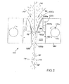
図2は、好適な空気延伸装置105の特定の実施態様を示す。しかし、本発明は図2の特定の構造に限定されず、特にガス流により、ポリマーメルトブローンフィラメントfを連続的に延伸及び細繊化するために使用されることができるいかなる延伸装置も包含する。
FIG. 2 shows a specific embodiment of a suitable
図2の特定の実施態様を参照すると、延伸装置105は、上方縦方向スロットタイプの入口1050aと下方縦方向スロットタイプの出口1050b(それらの両方は横方向(図2に垂直な方向)に延びる)を持つ垂直通路1050を含む。この通路1050は、メルトブローンフィラメントfのカーテンが通路1050を通過するような方法で、ダイヘッド104の出口(紡糸孔口の列)と垂直方向に一直線に並んでいる。通路1050のそれぞれの側方に、延伸装置105は、縦方向スロットタイプの開口1051a、1052a,1053aを通して連通する四つの室1051,1052,1053,1054を連続的に含む。最後の室1054は、縦方向スロットタイプの出口1054aを通して通路1050と連通している。最初の室1051は、縦方向スロットタイプの出口1055aを含む縦方向吹き込み導管1055を収容している。
Referring to the particular embodiment of FIG. 2, the stretching
操作において、吹き込み導管1055aは、周囲温度の加圧下のガス、特に周囲温度の加圧下の空気を供給される。この空気は、室1051においてスロットタイプの出口1055aを通して排出され、次いで室1052,1053及び1054内を連続的に通過する。この加圧下の空気は、通路1050において、スロットタイプの出口1054aを通して、高速度の下向き空気流F3の形で排出される。各スロットタイプの出口1054aは、空気流F3が下流にかつ実質的にフィラメントfの縦方向に、すなわち実質的にフィラメントfを形成するポリマーの流れと同じ縦方向の下流方向に配向される。
In operation, the blow-in
操作において、ポリマーメルトブローンフィラメントfは延伸装置105の通路1050を通過し、周囲温度でメルトブローンフィラメントfのカーテンの各側で通路中に、実質的にフィラメントfの縦方向に吹き込まれる空気流F3(図2)により延伸されかつ細繊化される。これらの空気流F3はまた、フィラメントfを冷却し、従ってフィラメントfの凝固(急冷)にも貢献する。
In operation, the polymer meltblown filament f passes through the
高速度空気流F3はまた、ベンチュリ効果により延伸装置105の上に空気吸引力を作る。この空気吸引力は、通路1050中に入口1050aを通して吸引されかつフィラメントfの冷却及び凝固に貢献する追加の空気流F4を作る。
The high velocity air flow F3 also creates an air suction force on the stretching
この延伸装置105では、空気流は、波動運動を与えるかまたはフィラメント内にうねりを作る乱流を作らない。この延伸装置105では、フィラメントは真直ぐなままであり、いかなる波動運動も持たない。
In this
空気流F1(ダイヘッド104)及びF3(延伸装置105)の速度は、有利には、延伸装置105の出口1050bでフィラメントfを破断しかつ予め決められた平均長さを持つ不連続メルトブローン繊維MFを形成するような方法で選ばれることができる(図2)。
The velocity of the air streams F1 (die head 104) and F3 (drawing device 105) is preferably such that the discontinuous meltblown fiber MF breaks the filament f at the
空気流F1及びF3の速度は、有利には別個に調整されることができ、それはメルトブロー装置10の設置の柔軟性を改善する。
The speeds of the air flows F1 and F3 can advantageously be adjusted separately, which improves the installation flexibility of the
特に、本発明では、延伸装置105とダイヘッド104の出口の間の距離は、フィラメントfを破断しかつ特定の平均長さの不連続非ステープル繊維を形成するために調整されることができる。好ましくは、延伸装置105とダイヘッド104の出口の間の距離は、フィラメントfを破断しかつ20mm以上、好ましくは40mmより大きく、かつ250mm以下、好ましくは150mm以下の平均長さを持つ不連続非ステープル繊維を形成するために調整されることができる。
In particular, in the present invention, the distance between the
この追加の延伸装置105の使用のおかげで、フィラメントfのポリマー鎖の延伸は、標準メルトブロー装置で実施される通常の延伸より大きくすることができ、それは、有利にはメルトブローン繊維MFの靭性を高めることができ、それによりかかる繊維を含むメルトブローン不織布ウエブMBWの靭性及びMD(機械方向)引張り強さを高めることができる。
Thanks to the use of this
本発明では、空気延伸装置105は、10μm未満、好ましくは2μm未満の平均直径を持つ非常に細かいデニールの繊維MFを製造するために使用されかつ調整されることができるが、有利には10μm以上、好ましくは10μm〜400μmの平均直径を持つ太い不連続非ステープル繊維MFを製造するために使用されかつ調整されることができる。
In the present invention, the
本発明の別の変形例では、空気流F1(ダイヘッド104)及びF3(延伸装置105)の速度はまた、有利には、延伸装置105のフィラメントfが出口1050bで破断されず、従って連続メルトブローン繊維MFを形成するような方法で選ばれることができる。
In another variant of the invention, the velocity of the air streams F1 (die head 104) and F3 (stretching device 105) is also advantageously such that the filament f of the stretching
空気延伸装置105の使用のおかげで、フィラメントを作るために使用されるポリマー(単数または複数)は、有利には、低いメルトフローインデックス、特に15〜70のメルトフローインデックス(ASTM D1238)を持つことができる。従って、非円形断面を持つが、例えば多裂片断面、特に二裂片断面を持つ造形された繊維を紡糸することができる。
Thanks to the use of the
図1の実施態様では、装置1はまた、ダイヘッド104から押出されるポリマーメルトブローンフィラメントfのカーテン内に繊維材料FMを連続的に組み入れるために、繊維材料FMの流れをダイヘッド104と延伸装置105の間の位置に供給するための供給手段13を含む。
In the embodiment of FIG. 1, the apparatus 1 also causes the flow of fiber material FM to flow between the
ここでかつ請求項で使用される用語「繊維材料」は、短い長さの繊維を含むか、及び/または粒子を含むいかなる材料も包含する。 The term “fibrous material” as used herein and in the claims encompasses any material comprising short lengths of fibers and / or particles.
繊維材料FMの繊維の平均長さは、一般的に、メルトブローン繊維MFの平均長さを越えないであろう。しかし、メルトブローン繊維MFの長さより大きい平均長さを持つ繊維材料のための繊維もまた、使用されることができる。 The average fiber length of the fiber material FM will generally not exceed the average length of the meltblown fiber MF. However, fibers for fiber materials having an average length greater than the length of the meltblown fibers MF can also be used.
特に、繊維材料は、有利には「パルプ」を含むことができる。 In particular, the fiber material can advantageously comprise “pulp”.
ここでかつ請求項で使用される用語「パルプ」は、木本及び非木本植物のような天然資源からの繊維から作られるかまたはそれを含む吸収性材料を示す。木本植物(すなわち木材パルプ)は、例えば落葉樹及び針葉樹を含む。非木本植物は、例えば綿、亜麻、エスパルト草、トウワタ、麦わら、ジュートヘンプ、及びバガスを含む。典型的には、パルプ繊維の平均長さは5mm以下である。しかし、より長い繊維も繊維材料FMのために使用されることができる。 The term “pulp” as used herein and in the claims refers to an absorbent material made from or comprising fibers from natural resources such as woody and non-woody plants. Woody plants (ie wood pulp) include, for example, deciduous trees and conifers. Non-woody plants include, for example, cotton, flax, esparto grass, milkweed, straw, jute hemp, and bagasse. Typically, the average length of pulp fibers is 5 mm or less. However, longer fibers can also be used for the fiber material FM.
本発明の範囲内では、繊維材料はパルプのみから作られることができるか、またはパルプと他の材料(繊維及び/または粒子)との乾燥混合物から作られることもできる。特に、繊維材料は、パルプと超吸収性材料(SAM)の粒子の乾燥混合物を含むことができる。 Within the scope of the present invention, the fiber material can be made from pulp alone, or it can be made from a dry mixture of pulp and other materials (fibers and / or particles). In particular, the fiber material can comprise a dry mixture of particles of pulp and superabsorbent material (SAM).
繊維材料はまた、ステープル繊維(天然及び/または合成)、例えば綿繊維を含むことができる。 The fibrous material can also include staple fibers (natural and / or synthetic), such as cotton fibers.
図1の特定の実施態様では、供給手段13は、その上部に繊維材料FMを空気圧式で供給する垂直煙突130を含む。煙突130の下部において、供給手段13は、煙突130の実質的に全幅で機械交差方向に縦方向に延びる二つの供給逆回転ロール131,132を含む。下方ロール132は、その全周に歯132aを備えている。
In the particular embodiment of FIG. 1, the supply means 13 includes a
供給手段13はまた、煙突の実質的に全幅で機械交差方向に延びる縦方向スロットタイプの出口134aを含む吹き込み手段134を含む。この吹き込み手段134は、前記出口134aを通して圧縮空気を吹き込むために適合されている。
The supply means 13 also includes blowing means 134 including a longitudinal
供給手段13はまた、供給ロール132の下に配置されている供給ノズル133を含む。このノズル133は繊維材料MFのための出口133aを持つ。前記出口133aは、縦方向スロットを形成し、ダイヘッド104と延伸装置105の間にかつメルトブローンフィラメントfのカーテンに近い位置に配置されている。この縦方向スロットタイプの出口133aは、繊維材料MFをメルトブローンフィラメントfのカーテンの実質的に全幅に供給するために、メルトブローンフィラメントfのカーテンの実質的に全幅に横方向(図1に対して垂直な方向)に延びる。
The supply means 13 also includes a
操作において、繊維材料Fは煙突130内に積み重ねられる。圧縮空気は、吹き込み手段134により、縦方向スロットタイプの出口134aを通してノズルの内側に連続的に排出される(空気流F5)。ロール131,132は、ノズル133に繊維材料MFを連続的に供給するために回転される。前記繊維材料MFは、吹き込み手段134によりノズル133の内側に発生された空気流F5により連行される。ノズル133の出口133aで、繊維材料MFは、メルトブローンフィラメントfのカーテンに近い位置に連続的に送出される。
In operation, the fiber material F is stacked in the
空気延伸装置105の使用のおかげで、繊維材料MFは、メルトブローンフィラメントfと接触状態で入り、延伸装置105に連行される。加えて、延伸装置105により作られた空気流F4(図2)のおかげで、繊維材料FMはまた、延伸装置105の通路1050中に吸引され、そこで繊維材料FMはポリマーフィラメントfと密接に混合される。
Thanks to the use of the
延伸装置105の出口1050bで、繊維材料FMは、有利には、メルトブローン繊維MFと密接に混合され、それと部分的に熱結合される。結果として、繊維含有メルトブローンウエブMBWがコンベヤーベルト11の表面11aの上に形成され、繊維材料MFとメルトブローン繊維MFの混ぜ合わせ及び結合が例えばRadwanskiらの米国特許第4931355号及び米国特許第4939016号に開示された技術解決策と比べて改善される。結果として、繊維含有メルトブローンウエブMBWが続けて固められ、及び/または取り扱われるときに繊維材料FMの損失が劇的に減少される。
At the
本発明では、追加の延伸装置105の使用はまた、Radwanskiらの米国特許第4931355号及び米国特許第4939016号に開示されたメルトブロー装置のように追加の延伸装置105を持たずにメルトブローンダイヘッドのみを持つ標準的なメルトブロー装置と比べて低速度の空気流F1及びF2を実行可能にする。空気流F1及びF2の速度を低下することにより、繊維材料FMが押し戻される危険が有利に少なくなる。結果として、メルトブローン繊維MFの内側により多い量の繊維材料を含めることが有利に容易になる。
In the present invention, the use of an
図1の特定の実施態様では、装置1はさらに、メルトブロー装置10から下流に配置されている固化手段14を含む。この特定の例では、これらの予備固化手段14は、従来技術で知られている熱結合装置によって構成される。この熱結合装置14は、二つの加圧ロール14a,14bを含むカレンダーである。下方ロール14bは滑らかな表面、例えばゴム表面を持つ。上方ロール14aは、ロールの全表面に渡って規則的に分配されかつ結合パターンを形成する、例えば突出リブを持つ彫られた表面を含む硬鋼ロールである。二つのロール14a,14bは、メルトブローン繊維MF、もし適切なら繊維材料が熱可塑性繊維を含むときは繊維材料FMの表面の軟化を得るために加熱される。
In the particular embodiment of FIG. 1, the apparatus 1 further includes solidification means 14 disposed downstream from the
操作において、繊維含有メルトブローン不織布ウエブMBWを熱及び機械的圧縮(熱結合)により予備固化するために二つのロール14a,14b間に繊維含有メルトブローン不織布ウエブMBWを輸送しかつ通過するために、コンベヤーベルト11が使用される。
In operation, a conveyor belt is used to transport and pass the fiber-containing meltblown nonwoven web MBW between the two
本発明は、繊維含有メルトブローン不織布ウエブMBWを固化するための熱結合装置の使用に限定されないが、例えば機械的結合、ハイドロエンタングリング、超音波結合、通気結合、及び接着剤結合のような業界で既知のいかなる他の固化技術も使用されることができる。 The present invention is not limited to the use of thermal bonding equipment to solidify fiber-containing meltblown nonwoven webs MBW, but includes industry such as mechanical bonding, hydroentangling, ultrasonic bonding, vent bonding, and adhesive bonding Any other solidification technique known in can be used.
一次熱空気F1は、一般的に、標準的なメルトブロー法と同様にダイヘッド104の外側に配置された熱源により空気を加熱することにより得られることができる。しかし、本発明の別の変形例では、加熱された空気は、この空気がダイヘッド104を通過するとき、ダイヘッド104により発生された熱によってのみ加熱されることができる。
The primary hot air F1 can generally be obtained by heating the air with a heat source located outside the
本発明の別の変形例では、図1の装置は、ポリマー材料がいかなる一次熱空気F1の発生もなしにフィラメントfの形でダイヘッド104内に押出されるだけであるような方法で変更されることができる。かかる場合には、フィラメントfを延伸及び細繊化するために延伸装置105のみが使用される。この場合には、ダイヘッド104の構造は簡略化されることができる。
In another variant of the invention, the apparatus of FIG. 1 is modified in such a way that the polymer material is only extruded into the
本発明の別の変形例では、一次空気F1は、この一次空気がダイヘッド104の出口でフィラメントfを延伸及び細繊化するために必然的に使用されないような方法で、しかしダイヘッド104を浄化するだけであり、破断フィラメントが紡糸孔口を損なうことを避けるような方法で低速度で発生されることができる。
In another variant of the invention, the primary air F1 cleans the
本発明の別の変形例では、図1の装置は、スパンボンデッドフィラメントMFが製造されるような方法で変更されることができる。 In another variation of the invention, the apparatus of FIG. 1 can be modified in such a way that a spunbonded filament MF is produced.
繊維MFを作るために使用されるポリマー(単数または複数)Pは、ダイヘッドを通して押出されることができるいかなる溶融紡糸可能なポリマー(単数または複数)であることもできる。良好な候補は、例えばポリオレフィン(特にポリプロピレンまたはポリエチレンのホモまたはコポリマー)、ポリエステルのホモまたはコポリマー、またはポリアミドのホモまたはコポリマーまたはそれらのブレンドである。それはまた、有利には、例えばポリ乳酸(PLA)のホモまたはコポリマーのようないかなる生分解性熱可塑性ポリマー、またはPLAのホモまたはコポリマーを含むいかなる生分解性ブレンドであることができる。かかる場合には、繊維材料が生分解性材料から作られるとき、不織布ウエブMBWは有利には完全に生分解性である。 The polymer (s) P used to make the fiber MF can be any melt-spinnable polymer (s) that can be extruded through a die head. Good candidates are, for example, polyolefins (especially polypropylene or polyethylene homo- or copolymers), polyester homo- or copolymers, or polyamide homo- or copolymers or blends thereof. It can also advantageously be any biodegradable thermoplastic polymer such as, for example, polylactic acid (PLA) homo- or copolymers, or any biodegradable blend comprising PLA homo- or copolymers. In such a case, the nonwoven web MBW is advantageously completely biodegradable when the fiber material is made from a biodegradable material.
繊維MFは一般的に非弾性であるだろう。しかし、エラストマーまたは弾性繊維MFもまた使用されることができる。 The fiber MF will generally be inelastic. However, elastomers or elastic fibers MF can also be used.
繊維MFは、単一成分または多成分繊維、特に二成分繊維、さらに特別には鞘/芯の二成分繊維であることができる。二成分繊維が製造されるとき、各ポリマーをダイヘッド104に同時に供給するために二つの押出し機が使用される。
The fibers MF can be single component or multicomponent fibers, in particular bicomponent fibers, more particularly sheath / core bicomponent fibers. When bicomponent fibers are produced, two extruders are used to feed each polymer to the
繊維MFのための断面の様々な形状もまた実行されることができる(丸い形状、楕円形状、多裂片形状、特に二裂片形状、三裂片形状など)。メルトブローン繊維MFの断面の形状は、ダイヘッド104の紡糸孔口の幾何学的形状により決定される。
Various shapes of cross-section for the fiber MF can also be implemented (round shape, oval shape, multi-strip shape, especially bi-strip shape, tri-strip shape, etc.). The shape of the cross section of the meltblown fiber MF is determined by the geometric shape of the spinning hole of the
しかし、繊維材料FMと繊維の結合は、驚くべきことに、多裂片形状の繊維MFが使用されるとき、特に図3に示されたもの、一般的に「ちょう形(papillon)」繊維と呼ばれるもののような二裂片繊維が使用されるとき、または図4に示されたもののような三裂片繊維が使用されるとき、改善される。 However, the bond between the fiber material FM and the fiber is surprisingly referred to as that shown in FIG. 3, generally referred to as “papillon” fiber, when multi-fibre shaped fiber MF is used. Improvements are made when bi-strip fibers such as those are used, or when tri-strip fibers such as those shown in FIG. 4 are used.
図5Aから5Cは、連続紡糸されたフィラメントから作られた下部スパンボンデッド不織布ウエブS、第一中間メルトブローンウエブMBW1、第二中間繊維含有メルトブローンウエブMBW2、第三中間繊維含有メルトブローンウエブMBW3、及び上部繊維含有メルトブローンウエブMBW4により構成された四層ラミネートを製造するための連続製造ラインの一例を示す。 5A to 5C show a lower spunbonded nonwoven web S made from continuously spun filaments, a first intermediate meltblown web MBW1, a second intermediate fiber-containing meltblown web MBW2, a third intermediate fiber-containing meltblown web MBW3, and an upper portion An example of the continuous production line for manufacturing the four-layer laminate comprised by the fiber containing melt blown web MBW4 is shown.
特に、この製造ライン2は、下部スパンボンデッド不織布ウエブSをコンベヤーベルト21上に連続的に供給するための供給手段20を含む(図5A)。この特定の例では、これらの供給手段20は、周りにスパンボンデッド不織布Sが巻かれている貯蔵ロール20aと、貯蔵ロール20aと組み合わされ、貯蔵ロール20aからスパンボンデッド不織布ウエブSを連続的に巻き戻し、このスパンボンデッド不織布ウエブSをコンベヤーベルト21上に置くために適合されている電動式ロール20bとを含む。これらの供給手段20はまた、コンベヤーベルト21上に直接無秩序に置かれる連続紡糸フィラメントから作られたスパンボンデッド不織布ウエブSをライン内で製造するために適合されたスパンボンデッド装置により置き換えられることができる。
In particular, the production line 2 includes supply means 20 for continuously supplying the lower spunbonded nonwoven web S onto the conveyor belt 21 (FIG. 5A). In this particular example, these supply means 20 are combined with a
これらの供給手段から下流に、製造ライン2は連続的に四つの装置22,23(図5B)、24及び25(図5C)を含む。装置23,24,25は、図1に関して前述した装置1と同一である。装置22は、図1の装置1に似ているが、繊維材料供給手段を含まない。
Downstream from these supply means, the production line 2 includes four devices 22, 23 (FIG. 5B), 24 and 25 (FIG. 5C) in succession. The
第一装置22は、第一メルトブローンウエブMBW1をスパンボンデッド不織布ウエブS上に直接連続的に紡糸するために使用される。第二装置23は、第二中間繊維含有メルトブローンウエブMBW2を第一メルトブローンウエブMBW1上に直接連続的に紡糸するために使用される。第三装置24は、第三繊維含有メルトブローンウエブMBW3を第二中間繊維含有メルトブローンウエブMBW2上に直接連続的に紡糸するために使用される。第四装置25は、繊維含有メルトブローンウエブMBW4を第三中間繊維含有メルトブローンウエブMBW3上に直接連続的に紡糸するために使用される。
The first apparatus 22 is used for directly and continuously spinning the first melt blown web MBW1 onto the spunbonded nonwoven web S. The
ラミネートMBW4/MBW3/MBW2/MBW1/Sは、次いでラミネートの異なる層を熱結合しかつ固化されたラミネートを得るために、標準的な熱結合装置26に続いて輸送される。固化されたラミネートMBW4/MBW3/MBW2/MBW1/Sは、次いで既知のようにライン内で貯蔵ロール27aの周りに巻かれる。
The laminate MBW4 / MBW3 / MBW2 / MBW1 / S is then transported following a standard
好適な実施態様では、第一及び第四のメルトブローン不織布ウエブMBW1及びMBW4のメルトブローン繊維は二裂片または三裂片であり、第二及び第三のメルトブローン不織布ウエブMBW2及びMBW3のメルトブローン繊維はいかなる形状も持つことができ、特に丸くすることができる。しかし、本発明は、かかる特定のラミネートに限定されない。 In a preferred embodiment, the meltblown fibers of the first and fourth meltblown nonwoven webs MBW1 and MBW4 are two or three pieces, and the meltblown fibers of the second and third meltblown nonwoven webs MBW2 and MBW3 have any shape. Can be rounded in particular. However, the present invention is not limited to such a specific laminate.
より一般的には、本発明の範囲内では、特にスパンボンデッド層、カードされた層、メルトブローン層、プラスチックフィルムを含む一つ以上の他の層をラミネートされた、本発明の少なくとも一つの繊維含有メルトブローンウエブを含むラミネートが有利に製造されることができる。 More generally, within the scope of the present invention, at least one fiber of the present invention laminated with one or more other layers, including in particular spunbonded layers, carded layers, meltblown layers, plastic films. Laminates containing the containing meltblown web can be advantageously produced.
本発明の繊維含有メルトブローンウエブまたは本発明の少なくとも一つの繊維含有メルトブローンウエブを含むラミネートが、吸収性製品、特にドライワイプ、またはウエットワイプ、またはおむつ、またはトレーニングパンツ、または衛生ナプキン、または失禁製品、またはベッドパッドを作るために有利に使用されることができる。 A fiber-containing meltblown web of the present invention or a laminate comprising at least one fiber-containing meltblown web of the present invention is an absorbent product, in particular a dry wipe, or a wet wipe, or a diaper, a training pant, or a sanitary napkin, or an incontinence product, Or it can be used advantageously to make bed pads.
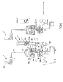
図6は、繊維含有不織布NWを作成するために使用されることができる本発明の紡糸装置1′の別の変形例を示す。 FIG. 6 shows another variation of the spinning device 1 ′ of the present invention that can be used to make a fiber-containing nonwoven fabric NW.
この変形例では、紡糸装置1′のダイヘッド104′は、図1の装置のための一つの列の代わりに、ポリマーフィラメントfの複数の列(この特定の例では三つの列)を押出すように変更されている。好ましくは、この紡糸装置1′では、いかなる一次熱空気F1のダイヘッド104′における発生もなく、ポリマーフィラメントfはダイヘッド104′の紡糸孔口を通して押出されるだけである。 In this variant, the die head 104 'of the spinning device 1' will extrude multiple rows of polymer filaments f (three rows in this particular example) instead of one row for the device of FIG. Has been changed. Preferably, in this spinning apparatus 1 ', the polymer filament f is only extruded through the spinning hole of the die head 104' without any primary hot air F1 being generated in the die head 104 '.
冷却装置106はダイヘッドの出口の下に取り付けられている。前記冷却装置106は、標準的なスパンボンド装置で使用される急冷空気と同様の方法でフィラメントfを冷却かつ急冷するために、フィラメントfの各側に配置されかつ複数の横断強制空気流F6をフィラメントfに向けて吹き込むために適合された二つの吹き込み箱106aを含む。急冷空気F6は、例えば5℃〜20℃の温度である。
The
前述したものと同じ下流配向された空気流F3を発生するために前述したものと同じ延伸装置105が、冷却装置106の下の位置で使用されており、前記空気流F3はフィラメントfを延伸及び細繊化する。
The
図1の第一実施態様の延伸装置105に関連して、特にフィラメントfを非ステープル不連続繊維MFに破断するためのこの延伸装置105の使用と関連してなされた全ての前述の説明は、図6の第二実施態様に対しても適用され、繰り返されないだろう。
In connection with the
図6の特定の実施態様では、繊維材料供給手段13′がまた、与えられている。前記繊維材料供給手段13′はまた、垂直煙突130を含み、それはその上方部において繊維材料FMを空気圧式に供給される。煙突130の下方部において、供給手段13′は、煙突130の実質的に全幅で機械交差方向に縦方向に延びる二つの供給逆回転ロール131,132を含む。下方ロール132は、その全周上に歯132aを備えている。
In the particular embodiment of FIG. 6, a fiber material supply means 13 'is also provided. Said fiber material supply means 13 'also includes a
供給手段13′はまた、供給ロール132の下に配置されている供給通路133′を含む。この供給通路133′は、繊維材料MFのための出口133aを持つ。前記出口133aは、縦方向スロットを形成し、冷却装置106と延伸装置105との間でフィラメントfのカーテンに近い位置に配置されている。この縦方向スロットタイプの出口133aは、実質的にフィラメントfのカーテンの全幅に繊維材料MFを供給するために、実質的にフィラメントfのカーテンの全幅で横方向(図6に垂直な方向)に延びる。
The supply means 13 ′ also includes a
図1の供給手段13とは対照的に、図6の供給手段13′は、吹き込み手段134を含まないが、供給通路133′の下方壁を形成しかつ繊維材料FMを下向きに出口133aに輸送するために適合されている。
In contrast to the supply means 13 of FIG. 1, the supply means 13 ′ of FIG. 6 does not include the blowing means 134, but forms the lower wall of the
操作において、繊維材料Fは煙突130内に積み重ねられる。コンベヤーベルト135は連続的に回転される。ロール131,132は、繊維材料MFをコンベヤーベルト135に連続的に供給するために回転される。前記繊維材料MFは、コンベヤーベルト135により連行され、フィラメントfのカーテンに近い位置に連続的に送出される。
In operation, the fiber material F is stacked in the
図6の変形例では、フラップ107と空気導管108により画定される案内通路106が、空気延伸装置105の出口とコンベヤーベルト11との間に延びている。かかる案内通路106は、米国特許出願US2008/0317895において従来から開示されており、それは参考としてここに組み込まれる。操作において、案内通路106の内側の空気圧を平衡にするために、空気が、案内通路106の外側から吸引され(矢印F7)、空気導管108を通して案内通路106中に入る。図1の装置はまた、かかる案内通路106、フラップ107、及び空気導管108を備えることができる。
In the variant of FIG. 6, a
図6の変形例では、二つの連続紡糸装置1′は同じコンベヤーベルト11を備えている。別の変形例では、紡糸装置1′は、単独で、または紡糸装置1′により製造された繊維含有不織布NWとあらゆる種類の層(織物層またはフィルム)をラミネートするために適合された他のいかなるタイプの装置と組み合わせても使用されることができる。
In the modification of FIG. 6, the two continuous spinning devices 1 ′ are provided with the
Claims (21)
(i)ポリマーメルトブローンフィラメント(f)を形成するためにダイヘッド(104)の紡糸孔口を通して少なくとも一種の溶融されたポリマー材料を押出すこと、
(ii)一次熱ガス流(F1)によりダイヘッド(104)の出口でメルトブローンフィラメントを延伸及び細繊化すること、
(iii)メルトブローンフィラメント(f)をさらに延伸及び細繊化するために、下流に配向されている追加のガス流(F3)を発生するためにダイヘッド(104)の下に配置された延伸装置(105)を使用すること
を含む方法であって、工程(iii)が、メルトブローンフィラメント(f)を不連続メルトブローン繊維(MF)に破断するような方法で実施されることを特徴とする方法。 As the following this:
(I) extruding at least one molten polymer material through a spinning hole in the die head (104) to form a polymer meltblown filament (f);
(Ii) stretching and thinning the meltblown filament at the outlet of the die head (104) with a primary hot gas flow (F1);
(Iii) A drawing device (under the die head (104) for generating an additional gas flow (F3) oriented downstream to further draw and refine the meltblown filament (f) 105) and the child to use
A method comprising: step (iii) being performed in such a manner that the meltblown filament (f) is broken into discontinuous meltblown fibers (MF).
Applications Claiming Priority (5)
| Application Number | Priority Date | Filing Date | Title |
|---|---|---|---|
| EP10172606 | 2010-08-12 | ||
| EP10172606.5 | 2010-08-12 | ||
| US201161468118P | 2011-03-28 | 2011-03-28 | |
| US61/468,118 | 2011-03-28 | ||
| PCT/EP2011/063770 WO2012020053A1 (en) | 2010-08-12 | 2011-08-10 | Process and apparatus for spinning fibres and in particular for producing a fibrous-containing nonwoven |
Related Child Applications (1)
| Application Number | Title | Priority Date | Filing Date |
|---|---|---|---|
| JP2016018030A Division JP2016145442A (en) | 2010-08-12 | 2016-02-02 | Process and apparatus for spinning fibres and in particular for producing fiber-containing nonwoven fabric |
Publications (3)
| Publication Number | Publication Date |
|---|---|
| JP2013536328A JP2013536328A (en) | 2013-09-19 |
| JP2013536328A5 JP2013536328A5 (en) | 2014-09-11 |
| JP5894598B2 true JP5894598B2 (en) | 2016-03-30 |
Family
ID=43587315
Family Applications (2)
| Application Number | Title | Priority Date | Filing Date |
|---|---|---|---|
| JP2013523608A Expired - Fee Related JP5894598B2 (en) | 2010-08-12 | 2011-08-10 | Method and apparatus for producing fibers, in particular for producing fiber-containing nonwovens |
| JP2016018030A Pending JP2016145442A (en) | 2010-08-12 | 2016-02-02 | Process and apparatus for spinning fibres and in particular for producing fiber-containing nonwoven fabric |
Family Applications After (1)
| Application Number | Title | Priority Date | Filing Date |
|---|---|---|---|
| JP2016018030A Pending JP2016145442A (en) | 2010-08-12 | 2016-02-02 | Process and apparatus for spinning fibres and in particular for producing fiber-containing nonwoven fabric |
Country Status (23)
| Country | Link |
|---|---|
| US (1) | US9617658B2 (en) |
| EP (2) | EP2603626B9 (en) |
| JP (2) | JP5894598B2 (en) |
| KR (1) | KR20130098330A (en) |
| CN (1) | CN103210133B (en) |
| AU (2) | AU2011288452B2 (en) |
| BR (1) | BR112013003040A2 (en) |
| CA (1) | CA2807482C (en) |
| CO (1) | CO6670547A2 (en) |
| DK (1) | DK2603626T3 (en) |
| ES (1) | ES2530952T3 (en) |
| HR (1) | HRP20150212T1 (en) |
| IL (1) | IL224653A (en) |
| MX (1) | MX2013001672A (en) |
| PL (1) | PL2603626T3 (en) |
| PT (1) | PT2603626E (en) |
| RS (1) | RS53822B1 (en) |
| RU (1) | RU2602481C2 (en) |
| SG (1) | SG187822A1 (en) |
| SI (1) | SI2603626T1 (en) |
| UA (1) | UA112528C2 (en) |
| WO (1) | WO2012020053A1 (en) |
| ZA (1) | ZA201301097B (en) |
Families Citing this family (21)
| Publication number | Priority date | Publication date | Assignee | Title |
|---|---|---|---|---|
| DE102012004227A1 (en) * | 2012-03-06 | 2013-09-12 | Carl Freudenberg Kg | Producing polymer fibers, preferably e.g. nonwoven fabric, comprises extruding polymer melt using spinning nozzle arrangement to obtain polymer fibers in free jet, stretching fibers using primary gas stream, and cooling and tempering fibers |
| CA2944618C (en) | 2014-04-07 | 2021-12-28 | Boma Engineering S.P.A | Process and apparatus for producing a fibrous-containing and/or particle-containing nonwoven |
| US10501875B2 (en) | 2014-08-27 | 2019-12-10 | Toray Industries, Inc. | Melt-blown nonwoven fabric and method of manufacturing same |
| JP6450145B2 (en) * | 2014-10-30 | 2019-01-09 | 日本製紙クレシア株式会社 | Nonwoven sheet for interpersonal wiping |
| TWI621742B (en) * | 2014-11-26 | 2018-04-21 | Method for preparing non-woven fabric with hygroscopic transferability by melt-blown method | |
| TWI621743B (en) * | 2014-11-26 | 2018-04-21 | Method for preparing moisture-absorbing transfer non-woven fabric by using short fiber spinning method | |
| TWI632259B (en) * | 2014-11-26 | 2018-08-11 | 聚泰環保材料科技股份有限公司 | Method for preparing moisture-absorbing transfer non-woven fabric by using spunbonding method |
| CN104630913B (en) * | 2015-02-05 | 2017-04-05 | 欣龙控股(集团)股份有限公司 | For the Spray Way and its device of melt blown non-woven production |
| US11313052B2 (en) * | 2015-08-14 | 2022-04-26 | The Board Of Regents Of The University Of Oklahoma | Melt blowing apparatus and method |
| DE102016010163A1 (en) * | 2016-08-25 | 2018-03-01 | Carl Freudenberg Kg | Technical packaging material |
| GB201619482D0 (en) | 2016-11-17 | 2017-01-04 | Teknoweb Marterials S R L | Triple head draw slot for producing pulp and spunmelt fibers containing web |
| CN110612206B (en) | 2017-03-27 | 2022-09-02 | 塞勒斯吸收性材料公司 | Absorbent laminate |
| CN106995983A (en) * | 2017-04-10 | 2017-08-01 | 河南工程学院 | A kind of production method of double component molten spraying super-fine-fiber net |
| EP3714086A4 (en) | 2017-11-22 | 2021-10-06 | Extrusion Group, LLC | Meltblown die tip assembly and method |
| CN108866828A (en) * | 2018-06-26 | 2018-11-23 | 海宁市御纺织造有限责任公司 | A kind of melt-blow nonwoven processing method containing staple fiber |
| BR112021025410A2 (en) * | 2019-07-18 | 2022-02-01 | Essity Hygiene & Health Ab | Sheet material, sheet material production process, cloth and sheet material usage |
| CN112064202B (en) * | 2020-09-04 | 2022-12-30 | 平湖爱之馨环保科技有限公司 | Auxiliary stretching equipment and method for fiber preparation |
| CN112411014A (en) * | 2020-10-12 | 2021-02-26 | 上海科械世贸易有限公司 | Production equipment and manufacturing method of melt-blown cloth containing nano silver wires |
| DE102021003877A1 (en) | 2021-07-27 | 2023-02-02 | Oerlikon Textile Gmbh & Co. Kg | Device for depositing fine filaments into a fleece |
| CN113684609A (en) * | 2021-09-04 | 2021-11-23 | 湖南仁瑞无纺制品有限公司 | Melt-blown non-woven fabric processing device |
| CN115233324B (en) * | 2022-08-05 | 2023-11-03 | 常州德利斯护理用品有限公司 | Spun-bonded drafting device for preparing special-shaped fibers with different cross sections |
Family Cites Families (36)
| Publication number | Priority date | Publication date | Assignee | Title |
|---|---|---|---|---|
| US3849241A (en) | 1968-12-23 | 1974-11-19 | Exxon Research Engineering Co | Non-woven mats by melt blowing |
| US4048364A (en) | 1974-12-20 | 1977-09-13 | Exxon Research And Engineering Company | Post-drawn, melt-blown webs |
| DE3151294C2 (en) * | 1981-12-24 | 1986-01-23 | Fa. Carl Freudenberg, 6940 Weinheim | Spunbonded polypropylene fabric with a low coefficient of fall |
| US4724114A (en) | 1984-04-23 | 1988-02-09 | Kimberly-Clark Corporation | Selective layering of superabsorbents in meltblown substrates |
| US4604313A (en) * | 1984-04-23 | 1986-08-05 | Kimberly-Clark Corporation | Selective layering of superabsorbents in meltblown substrates |
| DE3720031A1 (en) * | 1987-06-16 | 1989-01-05 | Freudenberg Carl Fa | SUCTION BODY MADE OF FLEECE AND PROCESS FOR PRODUCING IT |
| US4939016A (en) | 1988-03-18 | 1990-07-03 | Kimberly-Clark Corporation | Hydraulically entangled nonwoven elastomeric web and method of forming the same |
| US4931355A (en) | 1988-03-18 | 1990-06-05 | Radwanski Fred R | Nonwoven fibrous hydraulically entangled non-elastic coform material and method of formation thereof |
| DE3810596A1 (en) * | 1988-03-29 | 1989-10-12 | Bayer Ag | FINE FIBERS FROM POLYPHENYL SULFIDE |
| AU8275591A (en) | 1990-08-29 | 1992-03-05 | Chicopee | Spacer bar assembly for a melt blown die apparatus |
| US5075068A (en) * | 1990-10-11 | 1991-12-24 | Exxon Chemical Patents Inc. | Method and apparatus for treating meltblown filaments |
| US5350624A (en) * | 1992-10-05 | 1994-09-27 | Kimberly-Clark Corporation | Abrasion resistant fibrous nonwoven composite structure |
| US5503782A (en) * | 1993-01-28 | 1996-04-02 | Minnesota Mining And Manufacturing Company | Method of making sorbent articles |
| JP3418692B2 (en) * | 1995-03-20 | 2003-06-23 | 株式会社高分子加工研究所 | Manufacturing method of ultra high molecular weight polyolefin filament |
| US5648041A (en) * | 1995-05-05 | 1997-07-15 | Conoco Inc. | Process and apparatus for collecting fibers blow spun from solvated mesophase pitch |
| US5672415A (en) * | 1995-11-30 | 1997-09-30 | Kimberly-Clark Worldwide, Inc. | Low density microfiber nonwoven fabric |
| US5863565A (en) * | 1996-05-15 | 1999-01-26 | Conoco Inc. | Apparatus for forming a single layer batt from multiple curtains of fibers |
| US6001303A (en) | 1997-12-19 | 1999-12-14 | Kimberly-Clark Worldwide, Inc. | Process of making fibers |
| US6368533B1 (en) * | 1997-12-22 | 2002-04-09 | Kimberly-Clark Worldwide, Inc. | Process for forming films, fibers and base webs from thermoset polymers |
| UA30873A (en) | 1998-06-15 | 2000-12-15 | Криворізький Технічний Університет | Device for automated measurement of load mass on pit dump trucks |
| US6417120B1 (en) * | 1998-12-31 | 2002-07-09 | Kimberly-Clark Worldwide, Inc. | Particle-containing meltblown webs |
| JP3335949B2 (en) * | 1999-05-27 | 2002-10-21 | 有限会社末富エンジニアリング | Melt blown nonwoven spinning die |
| JP3865534B2 (en) * | 1999-07-05 | 2007-01-10 | ユニ・チャーム株式会社 | Method for producing elastic stretchable composite sheet |
| JP3662455B2 (en) | 1999-11-22 | 2005-06-22 | ユニ・チャーム株式会社 | Polypropylene nonwoven fabric and method for producing the same |
| US20020019614A1 (en) * | 2000-05-17 | 2002-02-14 | Woon Paul S. | Absorbent articles having improved performance |
| US6562282B1 (en) | 2000-07-20 | 2003-05-13 | Rtica, Inc. | Method of melt blowing polymer filaments through alternating slots |
| CN1847474B (en) * | 2000-08-04 | 2012-03-07 | 纳幕尔杜邦公司 | An extrusion die for meltblowing molten polymers |
| US6692868B2 (en) | 2001-12-19 | 2004-02-17 | Daramic, Inc. | Melt blown battery separator |
| US20030116874A1 (en) * | 2001-12-21 | 2003-06-26 | Haynes Bryan David | Air momentum gage for controlling nonwoven processes |
| JP4339054B2 (en) * | 2003-09-10 | 2009-10-07 | 株式会社パイオラックス | Grommet |
| US7150616B2 (en) | 2003-12-22 | 2006-12-19 | Kimberly-Clark Worldwide, Inc | Die for producing meltblown multicomponent fibers and meltblown nonwoven fabrics |
| ATE368759T1 (en) | 2004-09-17 | 2007-08-15 | Reifenhaeuser Gmbh & Co Kg | DEVICE FOR PRODUCING FILAMENTS FROM THERMOPLASTIC PLASTIC |
| US8137088B2 (en) | 2004-09-24 | 2012-03-20 | Oerlikon Textile Gmbh & Co. Kg | Device for depositing synthetic fibers to form a nonwoven web |
| CN1920149B (en) * | 2006-09-18 | 2011-05-04 | 中国纺织科学研究院 | Preparation method of meltblow nonwoven containing short fiber |
| US8246898B2 (en) | 2007-03-19 | 2012-08-21 | Conrad John H | Method and apparatus for enhanced fiber bundle dispersion with a divergent fiber draw unit |
| EP2119816B1 (en) | 2008-05-14 | 2011-01-05 | ALBIS Spa | Spinneret comprising bilobal spinning orifices |
-
2011
- 2011-08-10 EP EP11743819.2A patent/EP2603626B9/en active Active
- 2011-08-10 SG SG2013010483A patent/SG187822A1/en unknown
- 2011-08-10 AU AU2011288452A patent/AU2011288452B2/en not_active Ceased
- 2011-08-10 SI SI201130414T patent/SI2603626T1/en unknown
- 2011-08-10 KR KR1020137005896A patent/KR20130098330A/en not_active Application Discontinuation
- 2011-08-10 PL PL11743819T patent/PL2603626T3/en unknown
- 2011-08-10 JP JP2013523608A patent/JP5894598B2/en not_active Expired - Fee Related
- 2011-08-10 BR BR112013003040A patent/BR112013003040A2/en not_active IP Right Cessation
- 2011-08-10 US US13/816,079 patent/US9617658B2/en active Active
- 2011-08-10 PT PT11743819T patent/PT2603626E/en unknown
- 2011-08-10 ES ES11743819T patent/ES2530952T3/en active Active
- 2011-08-10 CA CA2807482A patent/CA2807482C/en active Active
- 2011-08-10 CN CN201180049605.4A patent/CN103210133B/en not_active Expired - Fee Related
- 2011-08-10 RS RS20150115A patent/RS53822B1/en unknown
- 2011-08-10 EP EP14184007.4A patent/EP2845936B1/en not_active Not-in-force
- 2011-08-10 DK DK11743819.2T patent/DK2603626T3/en active
- 2011-08-10 RU RU2013109811/12A patent/RU2602481C2/en not_active IP Right Cessation
- 2011-08-10 WO PCT/EP2011/063770 patent/WO2012020053A1/en active Application Filing
- 2011-08-10 MX MX2013001672A patent/MX2013001672A/en active IP Right Grant
- 2011-10-08 UA UAA201302830A patent/UA112528C2/en unknown
-
2013
- 2013-02-10 IL IL224653A patent/IL224653A/en active IP Right Grant
- 2013-02-11 ZA ZA2013/01097A patent/ZA201301097B/en unknown
- 2013-02-12 CO CO13028592A patent/CO6670547A2/en unknown
-
2015
- 2015-02-24 HR HRP20150212AT patent/HRP20150212T1/en unknown
-
2016
- 2016-02-02 JP JP2016018030A patent/JP2016145442A/en active Pending
- 2016-05-02 AU AU2016202798A patent/AU2016202798A1/en not_active Abandoned
Also Published As
Similar Documents
| Publication | Publication Date | Title |
|---|---|---|
| JP5894598B2 (en) | Method and apparatus for producing fibers, in particular for producing fiber-containing nonwovens | |
| KR101637620B1 (en) | A nonwoven composite and method for making the same | |
| CN104271827A (en) | Method of producing a hydroentangled nonwoven material | |
| EP1673500A1 (en) | Method and apparatus for the production of nonwoven web materials | |
| CN1458989A (en) | Meltblown web | |
| EP1101854A1 (en) | Nonwoven fabric of polypropylene fiber and process for making the same | |
| US20100159774A1 (en) | Nonwoven composite and method for making the same | |
| US20190284740A1 (en) | Triple head draw slot for producing pulp and spunmelt fibers containing web | |
| JP4334342B2 (en) | Filament drawing jet apparatus and method | |
| CN112105499B (en) | Composite sheet, system and method for preparing composite sheet | |
| JP4018784B2 (en) | Artificial leather made of non-woven fabric | |
| US20230067631A1 (en) | Nonwoven web with increased cd strength | |
| JPS5930825B2 (en) | Method for manufacturing heat-sealable fiber sheet | |
| JPS5930826B2 (en) | Method for manufacturing heat-sealable fiber sheet for interlining |
Legal Events
| Date | Code | Title | Description |
|---|---|---|---|
| A521 | Request for written amendment filed |
Free format text: JAPANESE INTERMEDIATE CODE: A523 Effective date: 20140728 |
|
| A621 | Written request for application examination |
Free format text: JAPANESE INTERMEDIATE CODE: A621 Effective date: 20140728 |
|
| A977 | Report on retrieval |
Free format text: JAPANESE INTERMEDIATE CODE: A971007 Effective date: 20150807 |
|
| A131 | Notification of reasons for refusal |
Free format text: JAPANESE INTERMEDIATE CODE: A131 Effective date: 20150818 |
|
| A601 | Written request for extension of time |
Free format text: JAPANESE INTERMEDIATE CODE: A601 Effective date: 20151105 |
|
| A521 | Request for written amendment filed |
Free format text: JAPANESE INTERMEDIATE CODE: A523 Effective date: 20160202 |
|
| TRDD | Decision of grant or rejection written | ||
| A01 | Written decision to grant a patent or to grant a registration (utility model) |
Free format text: JAPANESE INTERMEDIATE CODE: A01 Effective date: 20160223 |
|
| A61 | First payment of annual fees (during grant procedure) |
Free format text: JAPANESE INTERMEDIATE CODE: A61 Effective date: 20160226 |
|
| R150 | Certificate of patent or registration of utility model |
Ref document number: 5894598 Country of ref document: JP Free format text: JAPANESE INTERMEDIATE CODE: R150 |
|
| LAPS | Cancellation because of no payment of annual fees |