JP5893580B2 - Drying device for hair removal device and sterilization drying device for hair removal device - Google Patents
Drying device for hair removal device and sterilization drying device for hair removal device Download PDFInfo
- Publication number
- JP5893580B2 JP5893580B2 JP2013055990A JP2013055990A JP5893580B2 JP 5893580 B2 JP5893580 B2 JP 5893580B2 JP 2013055990 A JP2013055990 A JP 2013055990A JP 2013055990 A JP2013055990 A JP 2013055990A JP 5893580 B2 JP5893580 B2 JP 5893580B2
- Authority
- JP
- Japan
- Prior art keywords
- heater
- drying
- blower
- head
- hair removal
- Prior art date
- Legal status (The legal status is an assumption and is not a legal conclusion. Google has not performed a legal analysis and makes no representation as to the accuracy of the status listed.)
- Active
Links
- 238000001035 drying Methods 0.000 title claims description 149
- 210000004209 hair Anatomy 0.000 title claims description 116
- 238000004659 sterilization and disinfection Methods 0.000 title description 104
- 230000001954 sterilising effect Effects 0.000 title description 103
- 238000011068 loading method Methods 0.000 claims description 80
- 230000007613 environmental effect Effects 0.000 claims description 24
- 238000001514 detection method Methods 0.000 claims description 12
- 230000003993 interaction Effects 0.000 claims description 11
- 230000020169 heat generation Effects 0.000 claims description 6
- XLYOFNOQVPJJNP-UHFFFAOYSA-N water Substances O XLYOFNOQVPJJNP-UHFFFAOYSA-N 0.000 description 39
- 230000002093 peripheral effect Effects 0.000 description 18
- 238000005192 partition Methods 0.000 description 10
- 239000011941 photocatalyst Substances 0.000 description 10
- 230000009471 action Effects 0.000 description 8
- 238000000034 method Methods 0.000 description 8
- GWEVSGVZZGPLCZ-UHFFFAOYSA-N Titan oxide Chemical compound O=[Ti]=O GWEVSGVZZGPLCZ-UHFFFAOYSA-N 0.000 description 7
- 230000002070 germicidal effect Effects 0.000 description 7
- 239000000463 material Substances 0.000 description 7
- 244000052616 bacterial pathogen Species 0.000 description 6
- 239000005416 organic matter Substances 0.000 description 6
- 230000001699 photocatalysis Effects 0.000 description 6
- 239000013013 elastic material Substances 0.000 description 5
- 238000010438 heat treatment Methods 0.000 description 5
- 210000002374 sebum Anatomy 0.000 description 5
- 238000003860 storage Methods 0.000 description 5
- 238000005406 washing Methods 0.000 description 5
- 238000000354 decomposition reaction Methods 0.000 description 4
- 230000001678 irradiating effect Effects 0.000 description 4
- 230000008569 process Effects 0.000 description 4
- 208000019300 CLIPPERS Diseases 0.000 description 3
- 238000007664 blowing Methods 0.000 description 3
- 230000008859 change Effects 0.000 description 3
- 208000021930 chronic lymphocytic inflammation with pontine perivascular enhancement responsive to steroids Diseases 0.000 description 3
- 239000011248 coating agent Substances 0.000 description 3
- 238000000576 coating method Methods 0.000 description 3
- 238000001816 cooling Methods 0.000 description 3
- 238000001704 evaporation Methods 0.000 description 3
- 230000008020 evaporation Effects 0.000 description 3
- 238000005286 illumination Methods 0.000 description 3
- 229910052751 metal Inorganic materials 0.000 description 3
- 239000002184 metal Substances 0.000 description 3
- OGIDPMRJRNCKJF-UHFFFAOYSA-N titanium oxide Inorganic materials [Ti]=O OGIDPMRJRNCKJF-UHFFFAOYSA-N 0.000 description 3
- 241000894006 Bacteria Species 0.000 description 2
- 230000005540 biological transmission Effects 0.000 description 2
- 210000000078 claw Anatomy 0.000 description 2
- BASFCYQUMIYNBI-UHFFFAOYSA-N platinum Chemical compound [Pt] BASFCYQUMIYNBI-UHFFFAOYSA-N 0.000 description 2
- 238000003825 pressing Methods 0.000 description 2
- 238000007639 printing Methods 0.000 description 2
- 230000004044 response Effects 0.000 description 2
- 238000007789 sealing Methods 0.000 description 2
- 230000007480 spreading Effects 0.000 description 2
- 238000003892 spreading Methods 0.000 description 2
- 239000000758 substrate Substances 0.000 description 2
- 210000004243 sweat Anatomy 0.000 description 2
- WUPHOULIZUERAE-UHFFFAOYSA-N 3-(oxolan-2-yl)propanoic acid Chemical compound OC(=O)CCC1CCCO1 WUPHOULIZUERAE-UHFFFAOYSA-N 0.000 description 1
- RYGMFSIKBFXOCR-UHFFFAOYSA-N Copper Chemical compound [Cu] RYGMFSIKBFXOCR-UHFFFAOYSA-N 0.000 description 1
- BQCADISMDOOEFD-UHFFFAOYSA-N Silver Chemical compound [Ag] BQCADISMDOOEFD-UHFFFAOYSA-N 0.000 description 1
- 239000005083 Zinc sulfide Substances 0.000 description 1
- 230000004308 accommodation Effects 0.000 description 1
- 230000004913 activation Effects 0.000 description 1
- 230000008901 benefit Effects 0.000 description 1
- 229910052980 cadmium sulfide Inorganic materials 0.000 description 1
- 239000003990 capacitor Substances 0.000 description 1
- 239000003054 catalyst Substances 0.000 description 1
- 239000000919 ceramic Substances 0.000 description 1
- 238000005229 chemical vapour deposition Methods 0.000 description 1
- 238000004140 cleaning Methods 0.000 description 1
- 229910052802 copper Inorganic materials 0.000 description 1
- 239000010949 copper Substances 0.000 description 1
- 230000000249 desinfective effect Effects 0.000 description 1
- 238000010586 diagram Methods 0.000 description 1
- 238000010981 drying operation Methods 0.000 description 1
- 230000000694 effects Effects 0.000 description 1
- 238000004070 electrodeposition Methods 0.000 description 1
- 239000000796 flavoring agent Substances 0.000 description 1
- 230000000855 fungicidal effect Effects 0.000 description 1
- UQSXHKLRYXJYBZ-UHFFFAOYSA-N iron oxide Inorganic materials [Fe]=O UQSXHKLRYXJYBZ-UHFFFAOYSA-N 0.000 description 1
- 238000002844 melting Methods 0.000 description 1
- 230000008018 melting Effects 0.000 description 1
- 239000012528 membrane Substances 0.000 description 1
- 150000002739 metals Chemical class 0.000 description 1
- 238000002156 mixing Methods 0.000 description 1
- 239000012778 molding material Substances 0.000 description 1
- 238000012544 monitoring process Methods 0.000 description 1
- 239000010955 niobium Substances 0.000 description 1
- GUCVJGMIXFAOAE-UHFFFAOYSA-N niobium atom Chemical compound [Nb] GUCVJGMIXFAOAE-UHFFFAOYSA-N 0.000 description 1
- 229910000484 niobium oxide Inorganic materials 0.000 description 1
- 230000003287 optical effect Effects 0.000 description 1
- NDLPOXTZKUMGOV-UHFFFAOYSA-N oxo(oxoferriooxy)iron hydrate Chemical compound O.O=[Fe]O[Fe]=O NDLPOXTZKUMGOV-UHFFFAOYSA-N 0.000 description 1
- 239000002245 particle Substances 0.000 description 1
- 238000005240 physical vapour deposition Methods 0.000 description 1
- 229910052697 platinum Inorganic materials 0.000 description 1
- 230000001737 promoting effect Effects 0.000 description 1
- 230000001932 seasonal effect Effects 0.000 description 1
- 238000010008 shearing Methods 0.000 description 1
- 229910052709 silver Inorganic materials 0.000 description 1
- 239000004332 silver Substances 0.000 description 1
- 238000004528 spin coating Methods 0.000 description 1
- 239000007921 spray Substances 0.000 description 1
- 238000004544 sputter deposition Methods 0.000 description 1
- 239000000126 substance Substances 0.000 description 1
- 239000000725 suspension Substances 0.000 description 1
- 239000004408 titanium dioxide Substances 0.000 description 1
- 238000007740 vapor deposition Methods 0.000 description 1
- 239000002699 waste material Substances 0.000 description 1
- 239000002351 wastewater Substances 0.000 description 1
- 238000003466 welding Methods 0.000 description 1
- 229910052984 zinc sulfide Inorganic materials 0.000 description 1
- DRDVZXDWVBGGMH-UHFFFAOYSA-N zinc;sulfide Chemical compound [S-2].[Zn+2] DRDVZXDWVBGGMH-UHFFFAOYSA-N 0.000 description 1
Images


Landscapes
- Dry Shavers And Clippers (AREA)
Description
本発明は、電気かみそり、バリカン、脱毛器などの除毛器の除毛ヘッドを乾燥するための乾燥装置および除毛器の除毛ヘッドを除菌し乾燥するための除菌乾燥装置に関する。 The present invention relates to a drying device for drying a hair removal head of a hair removal device such as an electric razor, hair clipper or hair removal device, and a sterilization drying device for sterilizing and drying the hair removal head of a hair removal device.
この種の除菌乾燥装置は例えば特許文献1に開示してある。そこでは、水洗い式の電気かみそり用の乾燥器に、充電構造と乾燥構造を設けている。乾燥器は、載置凹部を備えたケーシングと、載置凹部の上面を開閉する蓋を備えており、蓋を開放した状態において、倒立姿勢にした電気かみそりを載置凹部に差込んで、水洗い後のかみそりヘッドを乾燥構造で乾燥できる。また、蓋を閉止した状態では、電気かみそりの充電プラグを蓋に設けたソケットに接続することにより、電気かみそりに内蔵された2次電池を充電できる。かみそりヘッドを乾燥する場合には、ヒーターと送風ファンを同時に駆動して、乾燥風をヒーターで加熱してかみそりヘッドへ向かって送給し、同時にかみそりヘッドの刃部に向かって紫外線をLEDで照射して除菌する。ヒーターのみを作動させて除菌モードにし、あるいは送風ファンのみを作動させて冷却モードにして使用することもできる。
This type of sterilization drying apparatus is disclosed in
例えば電気かみそりのかみそりヘッドに紫外光を照射して外刃および内刃を除菌する除菌装置は本出願人の出願に係る特許文献2の充電器に公知である。そこでは、充電器ベースの一側に、かみそりヘッドを保持するキャップを揺動可能に軸支し、ベースとキャップとで電気かみそりを横臥姿勢に支持した状態で、キャップの内部に設けた紫外光照射灯(以下、単にUV灯と言う。)で紫外光を照射して、外刃および内刃を除菌している。また、かみそりヘッドの内部には、充電器側のUV灯とは別にUV灯が設けてあるので、かみそりヘッドの内外両面から紫外光を照射して、さらに確実に除菌を行える。
For example, a sterilization apparatus for sterilizing an outer blade and an inner blade by irradiating an razor head of an electric razor with ultraviolet light is well known in the charger of
特許文献1の乾燥器によれば、水洗い後のかみそりヘッドを乾燥構造で乾燥し、あるいは電気かみそりの2次電池を充電構造で充電することができる。また、ヒーターの熱をかみそりヘッドに伝導して外刃および内刃を除菌し、さらに刃部に向かって紫外線をLEDで照射して除菌することができる。
According to the dryer of
特許文献2の充電器は、特許文献1の乾燥器のようにヒーターや送風ファンなどの乾燥構造を備えていないので、水洗い乾燥したかみそりヘッドは自然乾燥させる以外になく、乾燥に時間が掛かる。
Since the charger of
本発明の目的は、乾燥に要する処理時間を、季節あるいは気温の変化に対応して適正化できる除毛器用の乾燥装置を提供することにある。
本発明の目的は、ヒーターの熱による乾燥作用と、殺菌灯の照射光による殺菌作用とで、かみそりヘッドなどの除毛ヘッドの乾燥と、雑菌の除菌とを行える除毛器用の除菌乾燥装置を提供することにある。
本発明の目的は、水に濡れ、あるいは水洗い洗浄した除毛器の除菌乾燥機能に加えて、充電機能を備えた除毛器用の除菌乾燥装置を提供することにある。
The objective of this invention is providing the drying apparatus for hair removal devices which can optimize the processing time required for drying according to the change of a season or temperature.
The object of the present invention is to remove the hair of the hair removal head such as a razor head and disinfect bacteria by using the heat of the heater and the fungicidal action of the sterilizing light. To provide an apparatus.
An object of the present invention is to provide a sterilization drying apparatus for a hair removal device having a charging function in addition to a sterilization drying function of a hair removal device that has been wet or washed with water.
除毛器の除毛ヘッド2を乾燥するための乾燥装置である。乾燥装置のハウジング15には、除毛ヘッド2を支持するヘッド装填部21が設けられている。ヘッド装填部21に、除毛ヘッド2に対して乾燥用の熱を供給するヒーター76が設けられている。ヒーター76の近傍に、ヒーター76の駆動前には除毛器が置かれている環境温度を検知し、ヒーター76の駆動後にはヒーター温度を検知する温度センサー78が配置されている。
It is a drying device for drying the
ハウジング15に、ヒーター76の作動状態を制御する制御回路が設けられている。制御回路が、前記温度センサー78の環境温度の検知信号と、予め設定された温度条件とを比較して、乾燥する処理時間を環境温度に応じて大小に変更し、さらに、ヒーター76の駆動中には、温度センサー78の検知信号に応じて、ヒーター76の発熱温度を設定温度に維持するように構成されている。
A control circuit for controlling the operating state of the
ハウジング15に、乾燥風を送給する送風器24が設けられている。制御回路が、送風器24の起動に先行してヒーター76を駆動させ、所定時間が経過したのちに送風器24を起動させるように構成されている。送風器24の起動に先行してヒーター76の熱のみで除毛ヘッド2を乾燥し、次いで、ヒーター76の熱と送風器24から送給される乾燥風との相互作用で乾燥を行う。
The
制御回路が、送風器24の起動に先行してヒーター76を駆動させ、所定時間が経過したのちに送風器24を起動させるように構成されている。送風器24の起動に先行してヒーター76の熱のみで除毛ヘッド2を乾燥し、次いで、ヒーター76の熱と送風器24から送給される乾燥風との相互作用で乾燥を行う。その後、送風器24を停止させてヒーター76の熱のみで再度乾燥を行う。
The control circuit is configured to drive the
制御回路が、送風器24の起動に先行してヒーター76を駆動させ、所定時間が経過したのちに送風器24を起動させるように構成されている。送風器24の起動に先行してヒーター76の熱のみで除毛ヘッド2を乾燥し、次いで、ヒーター76の熱と送風器24から送給される乾燥風との相互作用で乾燥を行う。その後、送風器24を停止させてヒーター76の熱のみで再度乾燥を行う。さらにその後、ヒーター76の駆動を停止し、送風器24を起動して除毛ヘッド2を常温の乾燥風で冷却する。
The control circuit is configured to drive the
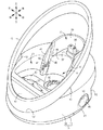
本発明は、除毛器の除毛ヘッド2を乾燥し除菌するための除菌乾燥装置に係り、図1に示すように、除菌乾燥装置のハウジング15には、除毛ヘッド2を支持するヘッド装填部21が設けてある。ヘッド装填部21に、除毛ヘッド2に対して乾燥用の熱を供給するヒーターユニット25と、除毛ヘッド2に殺菌光を照射する殺菌灯26とが配置してあることを特徴とする。
The present invention relates to a sterilization drying device for drying and sterilizing a
ヘッド装填部21に装填した除毛ヘッド2と正対するヘッド装填部21の底壁21bの内面に、ヒーターユニット25を構成するヒーター76を環状に配置する。ヒーター76で囲まれる空間に殺菌灯26を配置する。
A
ヘッド装填部21の底壁21bは、ヒーター76と対向する伝熱壁34と、殺菌灯26の配置領域と対向する導光壁35とで構成する。伝熱壁34は、熱伝導性に優れたゴム状の弾性材で形成する。導光壁35は、紫外光の透過を許す板材で形成する。
The
ヒーターユニット25は、図9に示すように、ヒーターベース75と、ヒーターベース75に環状に配置されるヒーター76と、ヒーター76と伝熱壁34との間に配置される金属板製の伝熱板77とを含んで構成する。導光壁35は、伝熱壁34に設けた窓開口33に装着されて、伝熱壁34で水密状に封止してある。
As shown in FIG. 9, the
ハウジング15の内部に、乾燥風を送給する送風器24を設ける。送風器24から送給された乾燥風をヘッド装填部21へ向かって送給案内するための乾燥風導入口32を、ヘッド装填部21の底壁21bに隣接して開口する(図8参照)。
A
ヘッド装填部21に隣接して、除毛器を支持する載置部22を凹み形成する。載置部22の底壁22bに乾燥風導入口32を開口する。
Adjacent to the
底壁21bを含むヘッド装填部21の下半部と、底壁22bを含む載置部22の下半部とは、熱伝導性に優れたゴム状の弾性材で形成したトレー体30として一体に形成する。
The lower half of the
載置部22の底壁22bに形成した乾燥風導入口は、除毛器からヘッド装填部21に流下した水の排水口32を兼ねる。
The drying air inlet formed in the
ヘッド装填部21の底壁21bを、ヘッド装填部21の側から載置部22の底壁22bの排水口32へ向かって下り傾斜させる。
The
ハウジング15に、ヘッド装填部21と、載置部22と、充電部23を記載順に配置する。ヘッド装填部21の底壁21bと、充電部23の基底部37に連続する載置部22の支持壁44とのそれぞれを、排水口32へ向かって下り傾斜させる。
In the
ヒーター76の近傍に、除毛器が置かれている環境温度を検知し、ヒーター76の駆動後にはヒーター温度を検知する温度センサー78を配置する。ハウジング15に、ヒーターユニット25、送風器24、および殺菌灯26の作動状態を制御する制御回路を設ける。制御回路は、前記温度センサー78の環境温度の検知信号と、予め設定された温度条件とを比較して、除菌乾燥する処理時間を環境温度に応じて大小に変更する。さらに、制御回路は、ヒーターユニット25の駆動中には、温度センサー78の検知信号に応じて、ヒーター76の発熱温度を設定温度に維持する。
In the vicinity of the
制御回路は、送風器24の起動に先行してヒーターユニット25を駆動させ、所定時間が経過したのちに送風器24を起動させるように構成する。送風器24の起動に先行してヒーター76の熱のみで除毛ヘッド2を除菌乾燥し、次いで、ヒーター76の熱と送風器24から送給される乾燥風との相互作用で除菌乾燥を行う。
The control circuit is configured to drive the
制御回路は、ヒーター76と送風器24とを駆動して所定時間が経過したのちに送風器24を停止させるように構成する。除菌乾燥過程の終段において、ヒーター76の熱のみで再度除菌乾燥を行う。
The control circuit is configured to drive the
制御回路は、除菌乾燥過程が終了した時点でヒーター76の駆動を停止し、送風器24を起動するように構成する。除菌乾燥過程の後に、除毛ヘッド2を常温の乾燥風で冷却する。
The control circuit is configured to stop driving the
除毛ヘッド2を構成する部品の表面に光触媒膜を形成する。
A photocatalytic film is formed on the surface of the parts constituting the
ヒーター76の近傍に、ヒーター76の駆動前には除毛器が置かれている環境温度を検知し、ヒーター76の駆動後にはヒーター温度を検知する温度センサー78が配置されることにより、1個の温度センサー78のみで環境温度とヒーター温度を検知でき、その分だけ乾燥装置の制御構造を簡素化できる。
A
温度センサー78の環境温度の検知信号と、予め設定された温度条件とを比較して、乾燥する処理時間を制御回路で環境温度に応じて大小に変更することにより、乾燥に要する処理時間を、季節あるいは気温の変化に対応して適正化できる。従って、乾燥を行った結果が、季節あるいは気温の変化によってばらつくのを解消して、除毛ヘッド2の乾燥を常に適正に行うことができる。また、ヒーター76の駆動時には、温度センサー78の検知信号に応じて、ヒーター76の発熱温度を制御回路で設定温度に維持することができる。
By comparing the detection signal of the environmental temperature of the
ヒーター76が送風器24の起動に先行して駆動されるように、両者24・76の駆動タイミングを制御すると、ヒーター76の熱で除毛ヘッド2を乾燥したのち、ヒーター76の熱と送風器24から送給される乾燥風との相互作用で乾燥を行うことができる。ヒーター76の熱で除毛ヘッド2を先行して加熱する状況では、除毛ヘッド2を構成する各部材の温度を所定の温度にまで高めて、各部材に付着した水の蒸発を促進できる。また、ヒーター76に加えて送風器24を駆動する状況では、ヒーター76の熱で蒸発した水蒸気を乾燥風で吹飛ばしながら、ヘッド装填部21の内部を乾燥しやすい状態に保持して、熱と風の相互作用で乾燥をさらに促進できる。
When the drive timing of both 24 and 76 is controlled so that the
ヒーター76の熱のみで再度加熱を行うように、ヒーター76および送風器24を制御すると、除毛ヘッド2を構成する各部材の温度を所定の温度にまで高めて、水が除去された状態の各部材を熱殺菌できる。従って、除毛ヘッド2の内外面を確実に殺菌乾燥させて衛生的な状態にすることができる。
When the
ヒーター76の駆動を停止し、送風器24を再び起動するようにヒーター76および送風器24を制御すると、加熱されていた除毛ヘッド2を乾燥風で冷却して常温の状態に戻すことができる。従って、乾燥装置で処理した直後に除毛器を使用するような場合であっても、ユーザーが除毛ヘッド2に触れて熱い思いをすることがなく、除毛器を連続して快適に使用できる。
When the
本発明においては、ハウジング15のヘッド装填部21にヒーターユニット25と殺菌灯26とを設けて、乾燥用の熱と殺菌光とを除毛ヘッド2に対して同時に作用させて除菌と乾燥を行なえるようにした。このように、除毛ヘッド2をヒーターユニット25の熱による加熱作用と、殺菌灯26の紫外光による殺菌作用とで除菌乾燥すると、除毛ヘッド2の内外に存在する雑菌を確実に殺菌し、雑菌が繁殖する余地のない乾燥状態を維持して、除毛ヘッド2を衛生的な状態に保持できる。
In the present invention, a
ヒーター76を環状に配置し、ヒーター76で囲まれる空間に殺菌灯26を配置すると、ヒーター76および殺菌灯26のそれぞれを、除毛ヘッド2に最も接近した状態で配置して、ヒーター76による加熱と殺菌灯26による殺菌とを効果的に行うことができる。また、ヒーター76による熱伝導領域と、殺菌灯26による殺菌領域を内外に隣接させて、空間の無駄がない状態でヒーター76と殺菌灯26を配置できるので、除菌乾燥のための構造をコンパクト化できる。
When the
伝熱壁34と導光壁35とでヘッド装填部21の底壁21bを構成し、伝熱壁34を熱伝導性に優れたゴム状の弾性材で形成すると、ヘッド装填部21に装填した除毛ヘッド2をクッション性を備えた伝熱壁34で受止めることができる。また、ヒーター76の熱を伝熱壁34を介して効果的に除毛ヘッド2に伝導できる。さらに、紫外光の透過を許す板材で形成した導光壁35で、除毛ヘッド2を安定した状態で受止めて支持できるので、全体として、ヘッド装填部21に装填した除毛ヘッド2に対する熱伝導と、殺菌光の照射とを効果的に行うことができる。
When the
ヒーターベース75と、ヒーター76と、伝熱板77などでヒーターユニット25を構成すると、ヒーター76の熱を伝熱板77で面状に拡散させた状態で伝熱壁34に伝導でき、従って、除毛ヘッド2の加熱をむらなく均等に行うことができる。また、伝熱壁34の窓開口33に装着した導光壁35を、伝熱壁34で水密状に封止することにより、ヘッド装填部21に装填した除毛ヘッド2から流落ちる水が、ヒーターユニット25の側へ浸入するのを確実に防止できる。伝熱壁34を利用して導光壁35の周囲を封止するので、別途、導光壁35用の封止構造を設ける必要がないうえ、外部衝撃を伝熱壁34で吸収して導光壁35が位置ずれするのを良く防止できる。
When the
ハウジング15の内部に送風器24を設け、送風器24から送給された乾燥風を、乾燥風導入口32を介してヘッド装填部21へ向かって送給できるようにすると、ヒーター76および殺菌灯26の除菌乾燥作用に加えて、乾燥風の乾燥促進作用によっても除毛ヘッド2の乾燥を促進できる。従って、除毛ヘッド2の内外面に付着した水分の蒸発を促進し、より短い時間で除菌乾燥を行うことができる。また、送給された乾燥風の一部は、伝熱壁34の熱や、除毛ヘッド2の熱で加熱されて相対湿度が低下するので、除毛ヘッド2の乾燥をさらに確実に行える。ヘッド装填部21の内部において除毛ヘッド2から蒸発した水蒸気を、乾燥風で除菌乾燥装置の外へ排出して、ヘッド装填部21の内部を乾燥しやすい状況に保持できる利点もある。
When the
ヘッド装填部21に隣接して載置部22を凹み形成し、その底壁22bに乾燥風導入口32を開口すると、不使用時の除毛器の本体部1を載置部22に装填し、その下部を乾燥風導入口32に差込むことにより、除菌乾燥装置を収納用のスタンドとして使用できる。また、除菌乾燥装置を収納用のスタンドとして使用する場合には、本体部1の下部が載置部22に入込む程度の大まかな操作で電気かみそりを適正に収納保管できる。さらに、本体部1を単に掴んで持ち上げるだけで、除毛器を除菌乾燥装置から取り出すことができ、その着脱を簡便に行える。
When the mounting
ヘッド装填部21の下半部と載置部22の下半部を、ゴム状の弾性材でトレー体30として一体に形成すると、ヘッド装填部21の底壁21bと、載置部22の底壁22bを個別に設ける場合に比べて、除菌乾燥装置の構成部品点数を減らすことができる。また、ヘッド装填部21および載置部22に装填した除毛器の重みを、ゴム状の弾性材からなる底壁21b・22bで受止めるので、ヘッド装填部21および載置部22に装填した除毛器が滑り動くのを、底壁21b・22bの摩擦力で阻止して、除毛器を安定した状態で支持できる。
When the lower half of the
乾燥風導入口が水の排水口32を兼ねるようにした除菌乾燥装置によれば、除毛器からヘッド装填部21または載置部22に流下した水を、排水口32から排出して、ヘッド装填部21および載置部22の底に水が溜るのを防止できる。また、ヘッド装填部21に装填した除毛ヘッド2の除菌乾燥を行う場合に、除毛ヘッド2から流れ落ちた水を、排水口32から速やかに排出して、除毛ヘッド2の乾燥を促進できる。
According to the sterilization drying apparatus in which the drying air introduction port also serves as the
ヘッド装填部21の底壁21bを排水口32へ向かって下り傾斜させると、除毛ヘッド2から流下した水または水滴を、確実に排水口32へ向かって流下し排水できるので、ヘッド装填部21における除毛ヘッド2の乾燥をさらに促進することができる。また、ヘッド装填部21に送給された乾燥風を底壁21bで流動案内し、ヘッド装填部21における乾燥風の通り抜けを促進して、除毛ヘッド2をさらに効果的に乾燥できる。
When the
ヘッド装填部21の底壁21bと、載置部22の支持壁44を排水口32へ向かって下り傾斜させると、水洗い洗浄した除毛器をヘッド装填部21、載置部22、あるいは充電部23に装填した状態において、除毛器から流れ落ちる水の全てを排水口32へ確実に流動案内できる。また、除毛器から流れ落ちた水を、底壁21bおよび支持壁44で集約して排水口32へ流動し排出するので、水がヘッド装填部21、載置部22、あるいは充電部23以外の部分に拡散し、あるいは除菌乾燥装置の周辺部に流れ出るのを防止できる。
When the
ヒーター76の近傍に配置した温度センサー78を利用して、除毛器が置かれている環境温度を検知し、さらに、駆動後のヒーター温度を検知すると、1個の温度センサー78のみで環境温度とヒーター温度を検知でき、その分だけ除菌乾燥装置の制御構造を簡素化できる。また、温度センサー78の環境温度の検知信号と、予め設定された温度条件とを比較して、除菌乾燥する処理時間を制御回路で環境温度に応じて大小に変更することにより、除菌乾燥に要する処理時間を、季節あるいは気温の変化に対応して適正化できる。従って、除菌乾燥を行った結果が、季節あるいは気温の変化によってばらつくのを解消して、除毛ヘッド2の除菌乾燥を常に適正に行うことができる。また、ヒーターユニット25の駆動時には、温度センサー78の検知信号に応じて、ヒーター76の発熱温度を制御回路で設定温度に維持することができる。
When the
ヒーターユニット25が送風器24の起動に先行して駆動されるように、両者24・25の駆動タイミングを制御すると、ヒーター76の熱で除毛ヘッド2を乾燥したのち、ヒーター76の熱と送風器24から送給される乾燥風との相互作用で乾燥を行うことができる。ヒーター76の熱で除毛ヘッド2を先行して加熱する状況では、除毛ヘッド2を構成する各部材の温度を所定の温度にまで高めて、各部材に付着した水の蒸発を促進できる。また、ヒーター76に加えて送風器24を駆動する状況では、ヒーター76の熱で蒸発した水蒸気を乾燥風で吹飛ばしながら、ヘッド装填部21の内部を乾燥しやすい状態に保持して、熱と風の相互作用で乾燥をさらに促進できる。
When the drive timing of both 24 and 25 is controlled so that the
除菌乾燥過程の終段においてヒーター76の熱のみで再度加熱を行うように、ヒーター76および送風器24を制御すると、除毛ヘッド2を構成する各部材の温度を所定の温度にまで高めて、水が除去された状態の各部材を熱殺菌できる。従って、除毛ヘッド2の内外面を確実に殺菌乾燥させて衛生的な状態にすることができる。
When the
除菌乾燥過程が終了した時点でヒーター76の駆動を停止し、送風器24を再び起動するようにヒーター76および送風器24を制御すると、加熱されていた除毛ヘッド2を乾燥風で冷却して常温の状態に戻すことができる。従って、除菌乾燥装置で処理した直後に除毛器を使用するような場合であっても、ユーザーが除毛ヘッド2に触れて熱い思いをすることがなく、除毛器を連続して快適に使用できる。
When driving of the
除毛ヘッド2を構成する部品の表面に光触媒膜を形成すると、光触媒膜が形成された部分に付着した毛屑、皮脂、汗などに含まれる有機物を光触媒膜で分解して、有機物の分解等による異臭の発生を防ぐことができ、除毛ヘッド2の内外面をさらに衛生的な状態に保持することができる。
When a photocatalytic film is formed on the surface of the parts constituting the
(実施例) 図1ないし図13は本発明に係る除毛器用の除菌乾燥装置の実施例を示しており、除毛器が電気かみそりである場合の除菌乾燥装置を示している。本発明における前後、左右、上下とは、図2および図3に示す交差矢印と、矢印の先端近傍の前後、左右、上下の表示に従うものとする。 (Example) FIG. 1 thru | or 13 has shown the Example of the disinfection drying apparatus for hair removal devices which concerns on this invention, and has shown the disinfection drying apparatus in case a hair removal device is an electric shaver. In the present invention, front / rear, left / right, and upper / lower refer to the cross arrows shown in FIGS. 2 and 3 and the front / rear, left / right, and upper / lower indications near the tip of the arrow.
図2において電気かみそりは、グリップを兼ねる本体部1と、本体部1の上部に設けられるかみそりヘッド(除毛ヘッド)2とを備えている。かみそりヘッド2には、網刃からなる断面アーチ形の一対の外刃3と、各外刃3の内面に摺接するロータリー式の内刃4・4と、センター刃とが設けられており、本体部1の内部に設けたモーター5の回転動力で、内刃4・4を回転駆動できる。かみそりヘッド2は水洗い洗浄することができ、洗浄時に内刃4・4を駆動することにより、かみそりヘッド2の内部に付着した毛屑や皮脂などを効果的に洗い流すことができる。
In FIG. 2, the electric razor includes a
本体部1にはモーター5に電力を供給する2次電池6が収容され、その前面にメインスイッチを切り換えるための押しボタン型のスイッチボタン7と、運転モードを表示するためのLED表示8などが設けてある。本体部1の下端には、給電用のプラグ9が設けてあり、このプラグ9を介して充電電流を供給することにより2次電池6を充電することができる。符号11は外刃3を支持する外刃ホルダーであり、その内部の毛屑室に切断された毛屑を溜めることができる。かみそりヘッド2の背面側には、図示していないきわ剃り刃ユニットの収容部10が本体部1と一体に設けてある(図10参照)。
A rechargeable battery 6 for supplying power to the motor 5 is housed in the
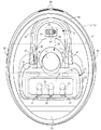
除菌乾燥装置は、平面視において前後方向に長い楕円状のハウジング15と、ハウジング15の前端から斜め後ろへ向かって上り傾斜する楕円形の保持リング16を備えている。図3ないし図5に示すように、ハウジング15は、ベース体17と、ベース体17の上面を覆うハウジング本体18などで構成されており、下向きに開口するハウジング本体18の上面側に、ヘッド装填部21と、載置部22と、充電部23が設けてある。また、ハウジング本体18の内部には、軸流ファン(送風器)24と、ヒーターユニット25と、紫外光(殺菌光)を照射する殺菌LED(殺菌灯)26と、排水パン27などが収容してある。
The sterilization drying apparatus includes an
ヘッド装填部21は、電気かみそりを倒立姿勢で支持して乾燥し殺菌するために設けてあり、載置部22は、電気かみそりを起立姿勢で収納支持するために設けてある。また、充電部23は、電気かみそりの2次電池6を充電するために設けてある。図6および図8に示すように、ヘッド装填部21と、載置部22と、充電部23は、ハウジング本体18の前部から後部へわたって記載順に配置してある。ヘッド装填部21と載置部22とが、それぞれハウジング本体18の上面に凹み形成されるのに対し、充電部23はハウジング本体18の上面よりも上向きに膨出する状態で形成してある。
The
ヘッド装填部21と載置部22とは、電気かみそりの支持空間を互いに共有する状態で前後に連続して形成してある。詳しくは、ヘッド装填部21に装填した状態の電気かみそり(図12参照)が占有する支持空間の一部と、載置部22に装填した状態の電気かみそり(図10参照)が占有する支持空間とが、前後に重なるように両載置部21・22が設けてある。図6に示すように、電気かみそりの本体部1の下部を受入れる載置部22は半楕円状の凹みとして形成してある。また、本体部1より広幅のかみそりヘッド2を受入れるヘッド装填部21は四隅が丸められた長方形状の凹みとして形成してあり、凹み後側の周囲壁の左右中央に載置部22が連続して形成してある。
The
図5に示すように、両載置部21・22の凹みの上周囲壁21a・22aはハウジング本体18と一体に形成してあり、両載置部21・22の凹みの下周囲壁(下半部)および底壁21b・22bは1個のトレー体30で形成してある。ヘッド装填部21の上周囲壁21aの前壁には、かみそりヘッド2を受止める3個の位置決めリブ31が突設してある。トレー体30は、耐熱性に富み、摩擦力が大きなゴム状弾性体を素材とする成形品からなり、その載置部22側の底壁22bには排水口32が開口され、ヘッド装填部21側の底壁21bには窓開口33が開口してある。
As shown in FIG. 5, the upper
排水口32は、軸流ファン24から送給される乾燥風を、ヘッド装填部21へ向かって送給案内する乾燥風導入口を兼ねている。ヘッド装填部21側の底壁21bは、窓開口33の周囲を囲む伝熱壁34と、窓開口33を塞ぐ窓板(導光壁)35とで構成されて、全体が排水口32へ向かって下り傾斜させてある。ヘッド装填部21の凹部の前壁には、先の位置決めリブ31に対応する位置決めリブ36が突設してある。これらのリブ31・36は、乾燥空気の排出路を確保する区分壁としても機能している。
The
充電部23は、載置部22の後側に隣接する状態で設けるが、載置部22の上開口縁に連続して載置部22より高い位置に形成する。充電部23は、水平の基底部37と、基底部37に膨出形成されるコネクター部38と、基底部37の周縁を囲むU字状の周壁39とで構成する。コネクター部38は、平面視が凸字状に形成してあり、その内部に電気かみそりのプラグ9を接続するための一対の端子板40が設けてある。
Although the charging
基底部37と載置部22の底壁22bとの段差部分には、載置部22に載置した電気かみそりの本体部1の周面を支持する支持壁44が設けてある。支持壁44は、底壁22bから基底部37へ向かって上り傾斜する傾斜壁で形成してあり、さらに支持壁44の横断面は、本体部1の周囲形状に対応して、充電部23の内部へ向かって内凹み状に湾曲させてある。支持壁44の左右側縁は、周壁39に連続するリブ壁41で覆われており、その上下中途部に受止段部42が形成してある。
A
上記のように、載置部22の左右両側をリブ壁41で覆うことにより、水洗い洗浄したかみそりヘッド2をヘッド装填部21に装填した状態において、本体部1あるいは収容部10などから滴る水滴が、周辺に流動し拡散するのを防止できる。また、受止めた水滴の全てを排水口32へと流下することができる。左右のリブ壁41の対向間隔は、収容部10の左右幅より僅かに大きく設定してある。支持壁44とリブ壁41との間に、ヘッド装填部21にかみそりヘッド2を装填した状態において、収容部10を受止めて電気かみそり全体を安定的に支持する座壁45が形成してある。
As described above, by covering the left and right sides of the mounting
ハウジング本体18の上面の前部には弦月形状の起動スイッチ51が配置されており、この起動スイッチ51の周囲を囲む状態で、保持リング16がハウジング本体18に固定してある。片持ち梁状に支持される保持リング16を強固に支持するために、ハウジング本体18の前部に支持段部52が形成され、さらにハウジング本体18の前部の左右に三角形状の受座53が突設してある(図8参照)。図8において符号54は溶着ピンであり、このピン54をハウジング本体18の前壁に係合したのち、先端を溶融変形することにより、保持リング16をハウジング本体18に固定できる。
A crescent moon-shaped
図4に示すように、ハウジング本体18の周囲壁の後部には、軸流ファン24用の吸気口55が多段溝状に開口してある。また、ハウジング本体18の周囲壁の左右には、排水パン27用の装着口56がトンネル断面状に形成され、右壁の後部に電源コード57のコードアーマー58を収容する凹部59が形成してある。
As shown in FIG. 4, an
図5に示すように、ベース体17の上面側は、その中途部上面に設けた区分壁60で前後に区分されており、区分壁60より前側に基板ユニット61を収容する区画が設けられ、区分壁60より後側にトレー体30、軸流ファン24、およびヒーターユニット25を収容する区画が設けてある。区分壁60より後側の区画の上面には、軸流ファン24から送出された乾燥空気を載置部22の排水口32へ向かって流動案内するガイドリブ62の一群が上突状に設けてある。図7に示すように、平面から見たときの区分壁60はC字状に形成してある。
As shown in FIG. 5, the upper surface side of the
区分壁60の傾斜壁には、殺菌LED26を差込むためのLED開口63が左右に長い長方形状に開口してある。さらに、ガイドリブ62の後方に軸流ファン24を支持するブラケット64が突設してある。区分壁60およびガイドリブ62の上縁部は、トレー体30の下面を支持する支持構造を兼ねている。詳しくは図8に示すように、ベース体17をハウジング本体18に組付けた状態において、ヘッド装填部21および載置部22の上周囲壁21a・22aの下開口と、区分壁60およびガイドリブ62の上縁部とで、トレー体30の周縁のフランジ部30aを挟持し、さらに、トレー体30の排水口32の凹面状の周囲壁をガイドリブ62で支持している。
In the inclined wall of the
図5に示すように、基板ユニット61は、カバー体67の上面に制御基板68を垂直姿勢で固定し、その前面側にスイッチ素子69と、スイッチ照明用のLED70とを実装し、その後面側に6個の殺菌LED26を配置して構成してある。起動スイッチ51は、スイッチ素子69の上方に配置されて、保持リング16とハウジング本体18で上下スライド自在に支持されており、カバー体67と起動スイッチ51との間に配置した左右一対のばね71で押し上げ付勢してある(図2参照)。
As shown in FIG. 5, the
図8に示すように、軸流ファン24は吸気口55に臨むベース体17の上面後部に配置されて、ブラケット64に傾斜する姿勢で固定してある。図9において、ヒーターユニット25は、左右に長い四角枠状のヒーターベース75と、ヒーターベース75の周囲に環状に配置されるシーズヒーター(ヒーター)76と、金属板製の伝熱板77と、発熱温度を監視する温度センサー78と、図示していない温度ヒューズなどで構成してある。温度センサー78は、シーズヒーター76を駆動した後のヒーター温度を検知するために設けてあるが、除菌乾燥装置の使用を開始する直前に、電気かみそりが置かれている環境温度を検知することにも利用される。ヒーターユニット25は、図7に示すように、LED開口63の上面側の周囲壁にビス79で固定されて、その伝熱板77がトレー体30の窓開口33の下面周縁に密着している(図1参照)。従って、シーズヒーター76の温熱(約65℃)を、伝熱板77を介してヘッド装填部21の伝熱壁34に伝導することができる。
As shown in FIG. 8, the
基板ユニット61をベース体17に組付けた状態では、6個の殺菌LED26がLED開口63内へ入込んで、窓開口33に嵌込んだ透明の窓板35と正対する。従って、殺菌LED26を点灯した状態では、窓板35を介してヘッド装填部21の内部へ紫外光を照射することができる。窓板35は窓開口33に嵌込まれて、その周縁が伝熱壁34で封止してある。従って、ヘッド装填部21に装填したかみそりヘッド2から洗浄水が流下する場合でも、水が窓開口33を介してヒーターユニット25の側へ浸入することはない。
In a state where the
図4および図5において、排水パン27は、左右に長い長方形状の浅い皿状部84と、皿状部84の左右両側に立設したつまみ部85とを一体に備えており、全体がハウジング本体18を左右に横断する状態で、装着口56に着脱自在に装着してある。詳しくは、つまみ部85の上部に設けた係合爪86を、装着口56の内面上方に設けた係合凹部87に係合することにより、排水パン27をハウジング本体18に固定できる。また、一対のつまみ部85を内向きに弾性変形させながら、係合爪86と係合凹部87の係合を解除することにより、排水パン27をハウジング本体18から取外すことができる。
4 and 5, the
図8に示すように、ハウジング本体18に装着した排水パン27の上面の後半部は、ベース体17の底壁88で覆われており、底壁88で覆われていない残りの部分は、底壁88に開口した開口89を介してトレー体30の排水口32と正対している。ベース体17に装着した排水パン27は、排水口32を介して視認することができる。従って、除菌乾燥装置を使用する際に、ハウジング15の上面側から排水口32を介して排水パン27を視認することにより、排水パン27の有無および装着状態を確認できる。
As shown in FIG. 8, the rear half of the upper surface of the
水洗い洗浄した電気かみそりは、かみそりヘッド2をヘッド装填部21に装填した状態で乾燥し除菌する。しかし、かみそりヘッド2がヘッド装填部21に装填されていない状態で、軸流ファン24、ヒーターユニット25、および殺菌LED26が作動すると、無駄な電力が消費されるのはもちろん、ヘッド装填部21の周囲壁が不必要に加熱されて高温になり、この高温部分に指先が触れて火傷するおそれがある。こうした、状況を確実に防止するために、片側のリブ壁41の段部46の上側にスイッチレバー92を設けている。
The electric razor washed and washed with water is dried and disinfected with the
図1に示すように、電気かみそりのかみそりヘッド2がヘッド装填部21に倒立姿勢で装填された状態において、スイッチレバー92が収容部10の突端で押し下げられてスイッチ素子93をオン操作する。この状態で、起動スイッチ51を押下げ操作することにより、軸流ファン24およびヒーターユニット25を起動させ、さらに殺菌LED26を点灯することができる。
As shown in FIG. 1, in a state where the
以上のように構成した除菌乾燥装置は、電気かみそりをヘッド装填部21と、載置部22と、充電部23のいずれかに載置した状態で使用する。不使用状態の電気かみそりを単に収納保管する場合には、図10に示すように、本体部1の下部を載置部22に差込み、本体部1の上部背面を保持リング16にもたれさせる。この状態の電気かみそりは、除菌乾燥装置の最も低い位置で支持されており、しかも、本体部1の上下2個所が載置部22と保持リング16との2個所で安定的に支持される。このとき、電気かみそりを載置部22に対して厳密に位置決めする必要はなく、本体部1の下部が載置部22に入込む程度の大まかな操作で電気かみそりを適正に収納保管できる。また、本体部1あるいはかみそりヘッド2を単に掴んで持ち上げるだけで、電気かみそりを除菌乾燥装置から簡便に取り出すことができる。
The sterilization / drying apparatus configured as described above is used in a state where the electric razor is placed on any of the
収納状態における電気かみそりは、本体部1の下部が排水口32に嵌まり込み、さらにゴム製のトレー体30の底壁22bで受止められるので、本体部1の下部が滑り動くのを良く防止できる。また、収納状態の電気かみそりは、除菌乾燥装置の最も低い位置で収納されるので、全高寸法を小さくでき、その分だけ収納スペースを小さくできる。
When the electric shaver is in the stored state, the lower part of the
2次電池6の充電を行う場合には、図11に示すように、本体部1の下端を充電部23のコネクター部38に差込んでプラグ9を端子版40に接続し、電気かみそりの全体を起立姿勢にする。この状態では、制御基板68に設けた充電回路から出力される充電電流をプラグ9を介して2次電池6に供給して、同電池6を充電できる。このとき、本体部1に設けたLED表示8を点灯させることにより、充電の進行状況を表示することができる。電気かみそりのプラグ9をコネクター部38に接続した状態では、本体部1の下部が基底部37から浮き離れている。そのため、本体部1に付着していた水または水滴が、基底部37へ流下することがあってもプラグ9が濡れることはなく、安全に充電を行える。
When charging the secondary battery 6, as shown in FIG. 11, the lower end of the
電気かみそりでひげ切断を行ったのち、水洗い洗浄したかみそりヘッド2を乾燥し除菌する場合には、図12に示すように、電気かみそりの全体を倒立姿勢にしたのち、かみそりヘッド2をヘッド装填部21に装填する。かみそりヘッド2をヘッド装填部21に装填した状態では、図1に示すように、その前面が位置決めリブ31・36で受止められ、さらに外刃3が窓板35で受止められている。また、収容部10の後面が座壁47の上下2個所で受止められ、収容部10の突端が受止段部42で受止められるため、倒立姿勢にした電気かみそりを、常に一定の姿勢にして安定した状態で支持できる。この装填過程で、スイッチレバー92が収容部10で押下げられてスイッチ素子93が給電回路を通電状態に切換える。
After drying the beard with an electric razor and then drying and disinfecting the
かみそりヘッド2をヘッド装填部21に装填した時点で、かみそりヘッド2の内部に入り込んでいた洗浄水が、外刃3を介してヘッド装填部21の底壁21b側へ流れ出る。しかし、底壁21bの全体が排水口32へ向かって下り傾斜させてあるため、外刃3から流出した洗浄水は排水口32の側へ流下し、さらに排水口32から排水パン27の皿状部84へと落下する。このとき、本体部1のスイッチボタン7をオン操作して内刃4を所定時間だけ空転させることにより、かみそりヘッド2の内部の洗浄水を効果的に排出することができる。
When the
上記の状態で起動スイッチ51を押込んでスイッチ素子69をオン操作することにより、軸流ファン24およびヒーターユニット25を起動させ、さらに殺菌LED26を点灯して、除菌乾燥運転を開始することができる。このとき、制御回路は図13に示すように、温度センサー78およびスイッチ素子93などの検知信号を受けて、各機器の作動状態を制御する。
By pressing the
以下、図14に示すタイミングチャートを参照しながら、各機器の起動タイミングおよび停止タイミングを説明する。起動スイッチ51がオン操作されると、制御回路はスイッチ素子93がスイッチレバー92でオン状態に切換えられていることを条件にして、まずスイッチ照明用のLED70を点灯させる。LED70は各機器が作動状態にあることを表示するパイロットランプであって、LED70が点灯することにより除菌乾燥装置が作動状態にあることを知ることができる。同時に、温度センサー78の環境温度の検知信号と、予め設定された温度条件とを比較して、除菌乾燥する処理時間を環境温度に応じて設定する。例えば、環境温度が15℃以上であれば、処理時間を80分+10分+5分とし、環境温度が15℃未満であれば、処理時間を170分+10分+5分に設定する。なお、基準となる環境温度は15℃である必要はなく、10℃、20℃、30℃など複数の環境温度を基準にして除菌乾燥の処理時間を適宜設定することができる。
Hereinafter, the start timing and stop timing of each device will be described with reference to the timing chart shown in FIG. When the
除菌乾燥する処理時間が設定されるのを待って(0.05秒後に)、ヒーターユニット25と殺菌LED26とに駆動電流を供給して前段の除菌乾燥処理を開始する。ヒーターユニット25と殺菌LED26による除菌乾燥処理は開始から30分間継続する。その間に伝熱壁34および窓板35からの伝導熱および放射熱によって、外刃3、内刃4、および外刃3を支持する外刃ホルダー11などを65℃まで加熱し、水滴を蒸発させることができる。同時に、6個の殺菌LED26から紫外光を照射して、外刃3、内刃4、および外刃ホルダー11などに付着している雑菌を殺菌できる。
After waiting for the processing time for sterilization and drying to be set (after 0.05 seconds), the driving current is supplied to the
除菌乾燥の開始から30分間が経過した時点で、軸流ファン24を起動して乾燥風をヘッド装填部21へ送給して、中段の除菌乾燥処理を行なう。図1および図8に示すように、軸流ファン24から送出された乾燥空気(加圧空気)は、トレー体30の載置部22側の底壁22bとベース体17の底壁88との間の隙間へ送給され、この隙間に設けたガイドリブ62で前向きに流動案内されたのち、排水口32からヘッド装填部21の凹部内へと入込んでかみそりヘッド2の表面に接触し、外刃3、内刃4、および外刃ホルダー11に付着した水滴を蒸発させる。さらに、かみそりヘッド2と窓板35との間の隙間を吹き抜ける乾燥空気で、かみそりヘッド2の周囲に蒸発した水蒸気を位置決めリブ31・36の間から上向きに排出する。このときの、外刃3、内刃4、および外刃ホルダー11の表面温度は、環境温度が20℃である場合に、乾燥風によって冷却されて45℃前後にまで低下する。
When 30 minutes have passed since the start of the sterilization drying, the
中段の除菌乾燥処理過程では、ヒーターユニット25による伝熱作用と、軸流ファン24の送風作用とによって、かみそりヘッド2の内外面に付着している水滴をさらに効果的に蒸発し乾燥させることができる。また、ヒーターユニット25による伝熱作用と並行して、殺菌LED26から紫外光を外刃3および内刃4に照射して、外刃3、内刃4、および外刃ホルダー11に付着している雑菌を殺菌し、あるいは水滴に含まれている雑菌を殺菌することができる。排水パン27に貯留されていた排水の一部は、中段の除菌乾燥処理を行なう過程で乾燥風に晒されて蒸発し、乾燥風とともに装置外へ排出される。
In the middle sterilization drying process, water droplets adhering to the inner and outer surfaces of the
起動スイッチ51がオン操作されてから所定時間(80分、または170分)が経過すると、軸流ファン24が停止され、ヒーターユニット25と殺菌LED26のみで後段の除菌乾燥処理を10分間行なう。この処理過程においては、外刃3、内刃4、および外刃ホルダー11などが、前段の除菌乾燥処理時と同様に65℃まで加熱される。従って、後段の除菌乾燥処理が終了した時点では、かみそりヘッド2の内外面を確実に乾燥させて衛生的な状態にすることができる。なお、後段の除菌乾燥処理を行う場合には、シーズヒーター76の出力を高く設定して、外刃3、内刃4、および外刃ホルダー11などを、前段あるいは中段の除菌乾燥処理時の加熱温度(65℃)より高い温度(80℃)に加熱することができる。
When a predetermined time (80 minutes or 170 minutes) elapses after the
後段の除菌乾燥処理が終了した時点で、ヒーターユニット25および殺菌LED26の作動を停止し、軸流ファン24を再度起動して冷却過程に移行する。軸流ファン24による冷却過程は開始から5分間だけ継続され、5分が経過した時点で軸流ファン24を停止し、スイッチ照明用のLED70を消灯し、除菌乾燥処理の全てを終了する。
When the subsequent sterilization drying process is completed, the operation of the
以上のように構成した除菌乾燥装置の制御回路は、軸流ファン24の起動に先行してヒーターユニット25を駆動させ、所定時間が経過したのちに軸流ファン24を起動させるように構成してある。これにより、軸流ファン24の起動に先行してヒーターユニット25の熱のみでかみそりヘッド2を除菌乾燥し、次いで、ヒーターユニット25の熱と軸流ファン24から送給される乾燥風との相互作用で除菌乾燥を行うことができる。
The control circuit of the sterilization drying apparatus configured as described above is configured to drive the
また、制御回路は、ヒーターユニット25と軸流ファン24とを駆動して所定時間が経過したのちに軸流ファン24を停止させるように構成してあり、これにより、除菌乾燥過程の終段において、ヒーターユニット25の熱のみで再度乾燥と殺菌を行うことができる。さらに、制御回路は、除菌乾燥過程が終了した時点でヒーターユニット25の駆動を停止し、軸流ファン24を起動するように構成してあり、これにより、除菌乾燥過程の後に、かみそりヘッド2を常温の乾燥風で冷却することができる。
In addition, the control circuit is configured to drive the
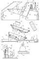
図15は本発明に係る除菌乾燥装置の別の実施例を示す。そこでは、ハウジング15を側面視でL字状に形成し、そのベース部分に充電部23を設けた。また、ハウジング15の上部にヘッド装填部21を設けて、ヘッド装填部21の内部にヒーターユニット25と殺菌LED26を配置した。ヘッド装填部21は、ハウジング15に対して軸95の周りに回動自在に連結されて、実線で示す除菌乾燥姿勢と、想像線で示す開放姿勢とに姿勢変更できる。符号96はヘッド装填部21を除菌乾燥姿勢の側へ向かって回動付勢する捻じりコイル形のばねである。軸95の下方のハウジング15の内部には、乾燥風をかみそりヘッド2へ送給するための軸流ファン24が配置してある。この実施例においても、リング状に配置したシーズヒーター76の内部に、6個の殺菌LED26を配置するようにした。
FIG. 15 shows another embodiment of the sterilization drying apparatus according to the present invention. In this case, the
充電部23は、ベース部分に凹み形成した基底部37と、基底部37に膨出したコネクター部38と、本体部1の下部の前後面を支持する周壁39とで構成してある。なお、図1から図12で説明した部材と同じ部材には、同じ符号を付してその説明を省略する。
The charging
かみそりヘッド2は、その構成部品の表面に光触媒膜を形成しておくことにより、毛屑室の内部をさらに衛生的な状態に保持することができる。具体的には、外刃3、内刃4の表面、外刃ホルダー11の内面、毛屑室の内周面のそれぞれに光触媒膜を形成することにより、皮脂や汗などに含まれる有機物を光触媒膜で分解して、有機物の分解等による異臭の発生を防ぐことができる。
The
光触媒膜は、酸化チタン、硫化カドミウム、硫化亜鉛、ニオブ、酸化第2鉄のいずれかひとつの光触媒材を含有する被膜からなり、スパッタリング、蒸着、CVD法、PVD法、電着法、あるいは塗布によって形成することができる。内刃4や外刃3等に光触媒材を塗布して光触媒膜を形成する場合には、例えば、酸化チタンゾル、無機コーティング材、硬化触媒を混合して得られる光触媒無機コーティング材を塗布し、常温であるいは数百度の熱を加えて硬化させて形成する。酸化チタンとしては、アナターゼ結晶形の二酸化チタンが好ましいが、銅、銀、白金、その他の金属でメタライズしたルチル形の二酸化チタンであってもよい。なお、光触媒材を含む懸濁液の塗付手段としては、ディップ法、スプレー法、静電印刷、インクジェット、タンポ印刷、スピンコーティングなどを適用できる。
The photocatalyst film is made of a film containing any one photocatalyst material of titanium oxide, cadmium sulfide, zinc sulfide, niobium, and ferric oxide, and is formed by sputtering, vapor deposition, CVD method, PVD method, electrodeposition method, or coating. Can be formed. When a photocatalyst material is applied to the
上記の光触媒膜は、近紫外光を照射することにより活性化されて有機物分解作用を発揮する。従って、殺菌LED26のいくつかが、波長が350〜370nmの近紫外光を放射できるようにしてあれば、近紫外光で毛屑や皮脂に付着している雑菌等を殺菌しながら、同時に光触媒膜を活性化させて有機物を分解できる。なお毛屑室の内周壁の殆どは、プラスチック成形された外刃ホルダー11、およびヘッドフレームで占められているので、これらに関しては光触媒膜を形成することに代えて、光触媒粒子を成形素材に混入して有機物分解作用を発揮させてもよい。
Said photocatalyst film | membrane is activated by irradiating near ultraviolet light, and exhibits an organic substance decomposition | disassembly effect | action. Accordingly, if some of the
上記の実施例では、プラグ9を介して2次電池6を充電するようにしたが、その必要はなく非接触式の充電構造で2次電池6を充電することができる。その場合には、充電部23の側に発振コイルを設け、電気かみそりの側に受信コイルとコンデンサー、および整流回路などを設けて、非接触状態で充電できるようにするとよい。
In the above embodiment, the secondary battery 6 is charged via the plug 9, but this is not necessary and the secondary battery 6 can be charged with a non-contact charging structure. In that case, an oscillating coil may be provided on the charging
送風器24は軸流ファンである必要はなく、遠心ファンやターボファンなどのファンを適用することができる。ヒーターユニット25の熱源はリング状に折曲げたシーズヒーターである必要はなく、リング状あるいはC字状などに形成したディスク状のセラミックヒーターを適用することができる。殺菌灯26としては紫外光を放射するランプ、あるいは蛍光灯であってもよい。ヒーター76は、ヘッド装填部21の内周面と対向する状態でC字状に配置することができ、その場合には、かみそりヘッド2の前面と両側面を加熱して除菌乾燥することができる。送風器24と排水口32との間に専用のヒーターを配置して、加熱された状態の乾燥風をヘッド装填部21へ送給することができる。
The
本発明は、電気かみそり以外に、バリカンあるいは脱毛器などの除毛器にも適用することができ、その場合のヘッド装填部21は、バリカンのせん断ヘッド、あるいは脱毛器の脱毛ヘッドの形状および構造に応じて、適合する形状および構造に形成するとよい。
The present invention can be applied to a hair remover such as a hair clipper or a hair remover in addition to an electric razor, and the
2 除毛ヘッド(かみそりヘッド)
15 ハウジング
17 ベース板
18 ハウジング本体
21 ヘッド装填部
21b ヘッド装填部の底壁
22 載置部
22b 載置部の底壁
23 充電部
24 送風器(軸流ファン)
25 ヒーターユニット
26 殺菌灯(殺菌LED)
32 排水口(乾燥風導入口)
34 伝熱壁
35 導光壁(窓板)
51 起動スイッチ
2 Hair removal head (razor head)
DESCRIPTION OF
25
32 Drain port (dry air inlet)
34
51 Start switch
Claims (4)
乾燥装置のハウジング(15)には、除毛ヘッド(2)を支持するヘッド装填部(21)が設けられており、
ヘッド装填部(21)に、除毛ヘッド(2)に対して乾燥用の熱を供給するヒーター(76)が設けられており、
ヒーター(76)の近傍に、ヒーター(76)の駆動前には除毛器が置かれている環境温度を検知し、ヒーター(76)の駆動後にはヒーター温度を検知する温度センサー(78)が配置されており、
ハウジング(15)に、ヒーター(76)の作動状態を制御する制御回路が設けられており、
制御回路が、前記温度センサー(78)の環境温度の検知信号と、予め設定された温度条件とを比較して、乾燥する処理時間を環境温度に応じて大小に変更し、さらに、ヒーター(76)の駆動中には、温度センサー(78)の検知信号に応じて、ヒーター(76)の発熱温度を設定温度に維持するように構成してあることを特徴とする除毛器用の乾燥装置。 A drying device for drying the hair removal head (2) of the hair remover,
The housing (15) of the drying device is provided with a head loading part (21) for supporting the hair removal head (2),
The head loading section (21) is provided with a heater (76) for supplying heat for drying to the hair removal head (2).
A temperature sensor (78) that detects the ambient temperature where the hair remover is placed in the vicinity of the heater (76) before the heater (76) is driven and detects the heater temperature after the heater (76) is driven. Has been placed ,
The housing (15) is provided with a control circuit for controlling the operating state of the heater (76),
The control circuit compares the detection signal of the environmental temperature of the temperature sensor (78) with a preset temperature condition, changes the processing time for drying to large or small according to the environmental temperature, and further, the heater (76 The hair dryer is configured to maintain the heat generation temperature of the heater (76) at a set temperature in accordance with the detection signal of the temperature sensor (78) during the driving of the temperature sensor (78) .
制御回路が、送風器(24)の起動に先行してヒーター(76)を駆動させ、所定時間が経過したのちに送風器(24)を起動させるように構成されており、
送風器(24)の起動に先行してヒーター(76)の熱のみで除毛ヘッド(2)を乾燥し、次いで、ヒーター(76)の熱と送風器(24)から送給される乾燥風との相互作用で乾燥を行う請求項1に記載の除毛器用の乾燥装置。 The housing (15) is provided with a blower (24) for feeding dry air,
The control circuit is configured to drive the heater (76) prior to the start of the blower (24) and to start the blower (24) after a predetermined time has elapsed,
Prior to the start of the blower (24), the hair removal head (2) is dried only by the heat of the heater (76), and then the heat of the heater (76) and the drying air supplied from the blower (24) The drying apparatus for a hair removal device according to claim 1, wherein drying is performed by interaction with the hair removal device.
送風器(24)の起動に先行してヒーター(76)の熱のみで除毛ヘッド(2)を乾燥し、次いで、ヒーター(76)の熱と送風器(24)から送給される乾燥風との相互作用で乾燥を行い、その後、送風器(24)を停止させてヒーター(76)の熱のみで再度乾燥を行う請求項2に記載の除毛器用の乾燥装置。 The control circuit is configured to drive the heater (76) prior to the start of the blower (24) and to start the blower (24) after a predetermined time has elapsed,
Prior to the start of the blower (24), the hair removal head (2) is dried only by the heat of the heater (76), and then the heat of the heater (76) and the drying air supplied from the blower (24) The drying apparatus for a hair remover according to claim 2, wherein drying is performed by interaction with the air and then the blower (24) is stopped and drying is performed again only with the heat of the heater (76) .
送風器(24)の起動に先行してヒーター(76)の熱のみで除毛ヘッド(2)を乾燥し、次いで、ヒーター(76)の熱と送風器(24)から送給される乾燥風との相互作用で乾燥を行い、その後、送風器(24)を停止させてヒーター(76)の熱のみで再度乾燥を行い、さらにその後、ヒーター(76)の駆動を停止し、送風器(24)を起動して除毛ヘッド(2)を常温の乾燥風で冷却する請求項3に記載の除毛器用の乾燥装置。 The control circuit is configured to drive the heater (76) prior to the start of the blower (24) and to start the blower (24) after a predetermined time has elapsed,
Prior to the start of the blower (24), the hair removal head (2) is dried only by the heat of the heater (76), and then the heat of the heater (76) and the drying air supplied from the blower (24) Then, the blower (24) is stopped, the drying is performed again only with the heat of the heater (76), and then the driving of the heater (76) is stopped, and the blower (24 ) Is activated to cool the hair removal head (2) with dry air at room temperature .
Priority Applications (1)
| Application Number | Priority Date | Filing Date | Title |
|---|---|---|---|
| JP2013055990A JP5893580B2 (en) | 2013-03-19 | 2013-03-19 | Drying device for hair removal device and sterilization drying device for hair removal device |
Applications Claiming Priority (1)
| Application Number | Priority Date | Filing Date | Title |
|---|---|---|---|
| JP2013055990A JP5893580B2 (en) | 2013-03-19 | 2013-03-19 | Drying device for hair removal device and sterilization drying device for hair removal device |
Related Parent Applications (1)
| Application Number | Title | Priority Date | Filing Date |
|---|---|---|---|
| JP2012055049A Division JP5866236B2 (en) | 2012-03-12 | 2012-03-12 | Disinfection and drying equipment for hair removal equipment |
Publications (3)
| Publication Number | Publication Date |
|---|---|
| JP2013188482A JP2013188482A (en) | 2013-09-26 |
| JP2013188482A5 JP2013188482A5 (en) | 2015-03-05 |
| JP5893580B2 true JP5893580B2 (en) | 2016-03-23 |
Family
ID=49389359
Family Applications (1)
| Application Number | Title | Priority Date | Filing Date |
|---|---|---|---|
| JP2013055990A Active JP5893580B2 (en) | 2013-03-19 | 2013-03-19 | Drying device for hair removal device and sterilization drying device for hair removal device |
Country Status (1)
| Country | Link |
|---|---|
| JP (1) | JP5893580B2 (en) |
Families Citing this family (1)
| Publication number | Priority date | Publication date | Assignee | Title |
|---|---|---|---|---|
| JP5893581B2 (en) * | 2013-03-19 | 2016-03-23 | 日立マクセル株式会社 | Drying device for hair removal device and sterilization drying device for hair removal device |
Family Cites Families (3)
| Publication number | Priority date | Publication date | Assignee | Title |
|---|---|---|---|---|
| JP4400646B2 (en) * | 2007-05-14 | 2010-01-20 | パナソニック電工株式会社 | Hair dryer |
| JP5866236B2 (en) * | 2012-03-12 | 2016-02-17 | 日立マクセル株式会社 | Disinfection and drying equipment for hair removal equipment |
| JP5893581B2 (en) * | 2013-03-19 | 2016-03-23 | 日立マクセル株式会社 | Drying device for hair removal device and sterilization drying device for hair removal device |
-
2013
- 2013-03-19 JP JP2013055990A patent/JP5893580B2/en active Active
Also Published As
| Publication number | Publication date |
|---|---|
| JP2013188482A (en) | 2013-09-26 |
Similar Documents
| Publication | Publication Date | Title |
|---|---|---|
| JP5893581B2 (en) | Drying device for hair removal device and sterilization drying device for hair removal device | |
| US8051579B2 (en) | Dryer for hair shaving device | |
| KR102054265B1 (en) | Puff sanitizer of cosmetics kit using UV LED | |
| JP5866236B2 (en) | Disinfection and drying equipment for hair removal equipment | |
| JP4400646B2 (en) | Hair dryer | |
| US20160066675A1 (en) | Hygienic razor blade dryer | |
| KR20220002986A (en) | Small UV light source device | |
| JP4329840B2 (en) | Hair dryer | |
| KR20190087038A (en) | Portable ultraviolet disinfection device for contact lenses | |
| JP5893444B2 (en) | Small electrical equipment stand | |
| JP5893580B2 (en) | Drying device for hair removal device and sterilization drying device for hair removal device | |
| KR20140107937A (en) | Apparatus for sterilizing and drying using plasma | |
| JP2012152330A (en) | Shoe dryer | |
| JP2004242970A (en) | Toothbrush sterilizing apparatus | |
| KR102183468B1 (en) | Skin cleansing device | |
| CN215386115U (en) | Ultraviolet disinfection dryer | |
| JP5960406B2 (en) | Toothbrush stand | |
| KR102348585B1 (en) | Cosmetic container | |
| KR20230071229A (en) | Vibration apparatus for face wasing | |
| KR20220087135A (en) | Ultraviolet sterilizing apparatus | |
| KR20220147952A (en) | Portable toothbrush sterilizer | |
| CN116499222A (en) | Cosmetic care product drying device | |
| JP2006345910A (en) | Bactericidal method and cleaned object drying apparatus | |
| JP2006181298A (en) | Warm air dryer | |
| KR20180085332A (en) | Puff sterilizating unit using UV-LED |
Legal Events
| Date | Code | Title | Description |
|---|---|---|---|
| A621 | Written request for application examination |
Free format text: JAPANESE INTERMEDIATE CODE: A621 Effective date: 20141218 |
|
| A521 | Request for written amendment filed |
Free format text: JAPANESE INTERMEDIATE CODE: A523 Effective date: 20141218 |
|
| A977 | Report on retrieval |
Free format text: JAPANESE INTERMEDIATE CODE: A971007 Effective date: 20151006 |
|
| A131 | Notification of reasons for refusal |
Free format text: JAPANESE INTERMEDIATE CODE: A131 Effective date: 20151222 |
|
| A521 | Request for written amendment filed |
Free format text: JAPANESE INTERMEDIATE CODE: A523 Effective date: 20160203 |
|
| TRDD | Decision of grant or rejection written | ||
| A01 | Written decision to grant a patent or to grant a registration (utility model) |
Free format text: JAPANESE INTERMEDIATE CODE: A01 Effective date: 20160223 |
|
| A61 | First payment of annual fees (during grant procedure) |
Free format text: JAPANESE INTERMEDIATE CODE: A61 Effective date: 20160224 |
|
| R150 | Certificate of patent or registration of utility model |
Ref document number: 5893580 Country of ref document: JP Free format text: JAPANESE INTERMEDIATE CODE: R150 |
|
| S531 | Written request for registration of change of domicile |
Free format text: JAPANESE INTERMEDIATE CODE: R313531 |
|
| S533 | Written request for registration of change of name |
Free format text: JAPANESE INTERMEDIATE CODE: R313533 |
|
| R350 | Written notification of registration of transfer |
Free format text: JAPANESE INTERMEDIATE CODE: R350 |
|
| R250 | Receipt of annual fees |
Free format text: JAPANESE INTERMEDIATE CODE: R250 |
|
| R250 | Receipt of annual fees |
Free format text: JAPANESE INTERMEDIATE CODE: R250 |
|
| R250 | Receipt of annual fees |
Free format text: JAPANESE INTERMEDIATE CODE: R250 |
|
| S533 | Written request for registration of change of name |
Free format text: JAPANESE INTERMEDIATE CODE: R313533 |
|
| R350 | Written notification of registration of transfer |
Free format text: JAPANESE INTERMEDIATE CODE: R350 |
|
| R250 | Receipt of annual fees |
Free format text: JAPANESE INTERMEDIATE CODE: R250 |
|
| R250 | Receipt of annual fees |
Free format text: JAPANESE INTERMEDIATE CODE: R250 |
|
| R250 | Receipt of annual fees |
Free format text: JAPANESE INTERMEDIATE CODE: R250 |