JP5889507B2 - Camera device, shooting timing notification method, shooting timing notification program - Google Patents
Camera device, shooting timing notification method, shooting timing notification program Download PDFInfo
- Publication number
- JP5889507B2 JP5889507B2 JP2008273674A JP2008273674A JP5889507B2 JP 5889507 B2 JP5889507 B2 JP 5889507B2 JP 2008273674 A JP2008273674 A JP 2008273674A JP 2008273674 A JP2008273674 A JP 2008273674A JP 5889507 B2 JP5889507 B2 JP 5889507B2
- Authority
- JP
- Japan
- Prior art keywords
- shooting
- photographing
- automatic
- lighting
- mode
- Prior art date
- Legal status (The legal status is an assumption and is not a legal conclusion. Google has not performed a legal analysis and makes no representation as to the accuracy of the status listed.)
- Expired - Fee Related
Links
Images


Description
本発明は、被写体となる者が視認し得る発光素子を備えたカメラ装置、及び撮影タイミング報知方法、撮影タイミング報知プログラムに関する。 The present invention relates to a camera device including a light emitting element that can be viewed by a person who is a subject, a shooting timing notification method, and a shooting timing notification program.
従来、所謂カメラ付き携帯電話機等のカメラ装置において、カメラ装置を操作している以外の者に対して、現在、撮影モードが設定されていることを知らせるための技術として、例えば下記特許文献1には、ユーザーにより撮影モードが設定されているとき、カメラ前面(撮像レンズの近傍等)に設けられているLEDインジケータを点滅させる技術が記載されている。係る技術によれば、撮影者においては、撮影のための準備を被写体となっている者に自ら要求する手間が無くなり、同時に被写体となっている者においては、必要となった時点で撮影に向けて顔の向きや表情を準備すればよい等、撮影時における利便性を向上させることができる。
しかしながら、上記技術においては単に操作者以外の者に対して撮影モードの設定の有無を知らせるものに過ぎないため、以下のような問題があった。すなわち一般に撮影モードが設定された後、実際に撮影が行われるタイミング(撮影タイミング)は様々であり、殊に撮影モードが複数設けられている場合には、その時々に使用される撮影モードの違いによって撮影タイミングはかなり異なっている。係ることから、上記技術においても、被写体となっている者に対して実際の撮影タイミングを正確に教えるまでには到らないという問題があった。 However, the above-described technique merely gives the person other than the operator the presence / absence of the shooting mode setting, and has the following problems. That is, in general, after the shooting mode is set, the actual shooting timing (shooting timing) varies, and particularly when a plurality of shooting modes are provided, the difference in the shooting mode used at that time is different. Depending on the shooting timing, it varies considerably. For this reason, the above-described technique also has a problem that it is not possible to accurately teach the actual photographing timing to the person who is the subject.
本発明は、かかる従来の課題に鑑みてなされたものであり、被写体となっている者に対して撮影モードの設定状態などによって変化する実際の撮影タイミングをより正確に教えることができるカメラ装置、及び撮影タイミング報知方法、撮影タイミング報知プログラムを提供することを目的とする。 The present invention has been made in view of such a conventional problem, and is a camera device capable of more accurately teaching an actual shooting timing that changes depending on a setting state of a shooting mode to a person who is a subject, It is another object of the present invention to provide a shooting timing notification method and a shooting timing notification program.
前記課題を解決するため請求項1記載の発明に係るカメラ装置にあっては、装置本体における画角内の任意の位置から視認可能な位置に設けられた発光素子と、撮影時に変化する基準情報の内容が予め決められた自動撮影の条件に該当する内容に変化した時点で自動的に撮影を行うとともに前記基準情報の変化に応じて前記発光素子の点灯パターンを順次変化させる自動撮影に関し、撮影指示からの経過時間を前記基準情報とする第1の撮影モードと、画像の振れ量を前記基準情報とするとともに前記点灯パターンを順次変化させる変化方法が前記第1の撮影モードとは異なる第2の撮影モードとを含む複数の撮影モードのいずれかを選択的に設定する撮影モード設定手段と、前記撮影モード設定手段により撮影モードが設定された後、自動露出制御、オートフォーカス制御、顔認識処理のうちの少なくとも1つを含む撮影準備動作を開始するとともに、撮影指示があると、前記撮影モード設定手段により設定された撮影モードに応じた基準情報の内容が該撮影モードに応じた自動撮影の条件を満たすまで待機し、該自動撮影の条件が満たされた後に撮影記録を行う一連の自動撮影動作を実行する撮影制御手段と、撮影制御手段により実行される前記一連の自動撮影動作に際し、撮影準備動作における所定のタイミングで所定の点灯パターンによって前記発光素子を点灯させるとともに、撮影指示があってから自動撮影の条件が満たされるまでの間、前記発光素子の点灯パターンを、前記撮影モード設定手段により設定された撮影モードに対応する前記変化方法により、前記基準情報の変化に応じて順次変化させる点灯制御手段とを備えたことを特徴とする。 In order to solve the above-described problem, in the camera device according to the first aspect of the present invention, the light emitting element provided at a position visible from an arbitrary position within the angle of view in the device main body, and reference information that changes at the time of shooting It relates to an automatic photographic contents of sequentially changing the lighting pattern of the light emitting element in accordance with a change in the reference information performs automatic photographing when you change the contents corresponding to the condition of a predetermined automatic photographing, photographing A first shooting mode in which the elapsed time from the instruction is the reference information, and a change method for sequentially changing the lighting pattern while using the shake amount of the image as the reference information are different from the first shooting mode. a photographing mode setting means for selectively setting one of a plurality of shooting modes including a shooting mode, after the shooting mode is set by the photographing mode setting means, the automatic Out control, autofocus control, starts the photographic preparation operation including at least one of the face recognition process, if there is a shooting instruction, the contents of reference information corresponding to the shooting mode set by the photographing mode setting unit Is executed by a shooting control means and a shooting control means for performing a series of automatic shooting operations for performing shooting and recording after the automatic shooting conditions are satisfied. In the series of automatic photographing operations, the light emitting element is turned on by a predetermined lighting pattern at a predetermined timing in the photographing preparation operation, and the light emitting element is in a period from when a photographing instruction is given until the automatic photographing condition is satisfied. the change by the method, the reference information of the lighting pattern corresponds to the shooting mode set by the photographing mode setting unit Characterized by comprising a lighting control unit that Ru is sequentially changed according to the change.
また、請求項2記載の発明に係るカメラ装置にあっては、前記点灯制御手段は、前記自動撮影の条件が成立した後であって前記撮影記録動作が完了していない期間に、動作状態の遷移に従って前記発光素子の点灯パターンを変化させることを特徴とする。
In the camera device according to a second aspect of the present invention, the lighting control means is in an operating state during a period in which the photographing / recording operation is not completed after the automatic photographing condition is satisfied . The lighting pattern of the light emitting element is changed according to the transition.
また、請求項3記載の発明に係るカメラ装置にあっては、前記点灯制御手段は、撮影制御手段により実行される前記一連の自動撮影動作に際し、前記自動撮影の条件が満たされるまでの間、前記発光素子を点灯させるときの点灯パターンを、前記基準情報の内容と前記自動撮影の条件との合致度合に応じて順次変化させることを特徴とする。 Further, in the camera device according to the invention of claim 3, the lighting control unit is in the series of automatic photographing operations executed by the photographing control unit until the automatic photographing condition is satisfied. A lighting pattern when the light emitting element is turned on is sequentially changed according to a degree of coincidence between the content of the reference information and the automatic photographing condition .
また、請求項4記載の発明に係るカメラ装置にあっては、前記基準情報は画像の振れ量であり、前記第2の撮影モードは、画像の振れ量が閾値以下となった時点が撮影タイミングとして決定する撮影モードであることを特徴とする。 In the camera device according to the fourth aspect of the invention, the reference information is an image shake amount, and the second shooting mode has a shooting timing when the image shake amount becomes a threshold value or less. The shooting mode is determined as follows.
また、請求項5記載の発明に係るカメラ装置にあっては、前記点灯制御手段は、撮影指示があってから設定時間が経過した時点を撮影タイミングとして決定する前記第1の撮影モードによる自動撮影動作に際し、前記点灯制御に伴い前記発光素子を点灯させるときの点灯パターンを、撮影指示があったからの経過時間に応じて変化させることを特徴とする。
In the camera device according to claim 5, the lighting control unit is configured to automatically shoot in the first shooting mode in which a set time elapses after the shooting instruction is given as a shooting timing. In operation, the lighting pattern when the light emitting element is turned on in accordance with the lighting control is changed according to the elapsed time since the photographing instruction is given.
また、請求項6記載の発明に係るカメラ装置にあっては、動画撮影機能を備えるとともに、前記自動撮影動作は静止画撮影を目的とした自動撮影動作であって、前記点灯制御手段は、動画撮影期間中に実施される静止画撮影を目的とした自動撮影動作に際しても、当該自動撮影動作中に順に遷移する一連の動作状態に応じて前記発光素子の点灯を制御するとともに、当該点灯制御に伴い前記発光素子を前記特定の点灯パターンで点灯させることを特徴とする。 Further, in the camera apparatus according to the invention of claim 6, provided with a video recording function, the automatic photographing operation is an automatic photographing operation for the purpose of still image shooting, the lighting control means, moving Even during an automatic shooting operation for the purpose of still image shooting performed during the shooting period, the lighting element is controlled to be turned on in accordance with a series of operation states that sequentially change during the automatic shooting operation, and the lighting control is performed. Accordingly, the light emitting element is turned on with the specific lighting pattern.
また、請求項7記載の発明に係るカメラ装置にあっては、撮像手段により撮像される画像を表示する表示手段と、前記自動撮影動作に際し、当該自動撮影動作に含まれる一連の動作状態を前記表示手段に表示させる動作情報表示手段と、をさらに備えたことを特徴とする。 In the camera device according to the seventh aspect of the present invention, the display means for displaying an image picked up by the image pickup means, and a series of operation states included in the automatic photographing operation at the time of the automatic photographing operation, And an operation information display means for displaying on the display means.
また、請求項8記載の発明に係るカメラ装置にあっては、前記動作情報表示手段は、前記点灯制御手段による前記点灯制御に伴う発光素子の点灯に連動し、前記表示手段に前記動作状態を表示させることを特徴とする。 In the camera device according to the eighth aspect of the present invention, the operation information display means is interlocked with the lighting of the light emitting element accompanying the lighting control by the lighting control means, and the operation status is indicated on the display means. It is characterized by being displayed .
また、請求項9記載の発明に係るカメラ装置にあっては、前記動作情報表示手段は、前記点灯制御手段による前記点灯制御に伴う発光素子の点灯に連動することなく前記表示手段に前記動作状態を表示させることを特徴とする。 Further, in the camera device according to the ninth aspect of the present invention, the operation information display means includes the operation state on the display means without being interlocked with the lighting of the light emitting element accompanying the lighting control by the lighting control means. Is displayed .
また、請求項10記載の発明に係るカメラ装置にあっては、前記点灯パターンは、点灯色、点滅速度、点灯回数のうち少なくともいずれか1つにより特徴づけられていることを特徴とする。 In the camera device according to a tenth aspect of the present invention, the lighting pattern is characterized by at least one of a lighting color, a blinking speed, and a lighting frequency .
また、請求項11記載の発明に係る撮影タイミング報知方法にあっては、装置本体における画角内の任意の位置から視認可能な位置に発光素子が設けられたカメラ装置における撮影タイミング報知方法であって、撮影時に変化する基準情報の内容が予め決められた自動撮影の条件に該当する内容に変化した時点で自動的に撮影を行うとともに前記基準情報の変化に応じて前記発光素子の点灯パターンを順次変化させる自動撮影に関し、撮影指示からの経過時間を前記基準情報とする第1の撮影モードと、画像の振れ量を前記基準情報とするとともに前記点灯パターンを順次変化させる変化方法が前記第1の撮影モードとは異なる第2の撮影モードとを含む複数の撮影モードのいずれかを選択的に設定する撮影モード設定処理と、前記撮影モード設定処理により撮影モードが設定された後、自動露出制御、オートフォーカス制御、顔認識処理のうちの少なくとも1つを含む撮影準備動作を開始するとともに、撮影指示があると、前記撮影モード設定処理により設定された撮影モードに応じた基準情報の内容が該撮影モードに応じた自動撮影の条件を満たすまで待機し、該自動撮影の条件が満たされた後に撮影記録を行う一連の自動撮影動作を実行する撮影制御処理と、撮影制御処理により実行される前記一連の自動撮影動作に際し、撮影準備動作における所定のタイミングで所定の点灯パターンによって前記発光素子を点灯させるとともに、撮影指示があってから自動撮影の条件が満たされるまでの間、前記発光素子の点灯パターンを、前記撮影モード設定処理により設定された撮影モードに対応する前記変化方法により、前記基準情報の変化に応じて順次変化させる点灯制御処理とを含むことを特徴とする。
In addition, the shooting timing notification method according to the invention of
また、請求項12記載の発明に係る撮影タイミング報知プログラムにあっては、装置本体における画角内の任意の位置から視認可能な位置に発光素子が設けられたカメラ装置が有するコンピュータを、撮影時に変化する基準情報の内容が予め決められた自動撮影の条件に該当する内容に変化した時点で自動的に撮影を行うとともに前記基準情報の変化に応じて前記発光素子の点灯パターンを順次変化させる自動撮影に関し、撮影指示からの経過時間を前記基準情報とする第1の撮影モードと、画像の振れ量を前記基準情報とするとともに前記点灯パターンを順次変化させる変化方法が前記第1の撮影モードとは異なる第2の撮影モードとを含む複数の撮影モードのいずれかを選択的に設定する撮影モード設定手段と、前記撮影モード設定手段により撮影モードが設定された後、自動露出制御、オートフォーカス制御、顔認識処理のうちの少なくとも1つを含む撮影準備動作を開始するとともに、撮影指示があると、前記撮影モード設定手段により設定された撮影モードに応じた基準情報の内容が該撮影モードに応じた自動撮影の条件を満たすまで待機し、該自動撮影の条件が満たされた後に撮影記録を行う一連の自動撮影動作を実行する撮影制御手段と、撮影制御手段により実行される前記一連の自動撮影動作に際し、撮影準備動作における所定のタイミングで所定の点灯パターンによって前記発光素子を点灯させるとともに、撮影指示があってから自動撮影の条件が満たされるまでの間、前記発光素子の点灯パターンを、前記撮影モード設定手段により設定された撮影モードに対応する前記変化方法により、前記基準情報の変化に応じて順次変化させる点灯制御手段として機能させることを特徴とする。
In the shooting timing notification program according to the twelfth aspect of the invention, a computer having a camera device provided with a light emitting element at a position that can be viewed from an arbitrary position within the angle of view of the apparatus main body is recorded during shooting. automatic contents of the changing reference information sequentially changing the lighting pattern of the light emitting element in accordance with a change in the reference information performs automatic photographing when you change the contents corresponding to the condition of a predetermined automatic photographing Regarding shooting, a first shooting mode in which an elapsed time from a shooting instruction is used as the reference information, and a change method in which an image shake amount is used as the reference information and the lighting pattern is sequentially changed are the first shooting mode. a plurality of the photographing mode setting means for selectively setting one of the photographing mode, the photographing mode setting means including a different second imaging mode After being set more shooting modes, automatic exposure control, automatic focus control, it starts the photographic preparation operation including at least one of the face recognition process, if there is a shooting instruction, set by the photographing mode setting unit Shooting that executes a series of automatic shooting operations in which the contents of the reference information according to the shooting mode satisfy the conditions of automatic shooting according to the shooting mode and perform shooting and recording after the automatic shooting conditions are satisfied In the series of automatic photographing operations executed by the control means and the photographing control means, the light emitting element is turned on by a predetermined lighting pattern at a predetermined timing in the photographing preparation operation, and automatic photographing conditions are given after a photographing instruction is given. until is satisfied, the lighting pattern of the light emitting element, the photographing mode setting against the shooting mode set by means By the change method of, wherein the function as the lighting control means Ru is sequentially changed according to the change of the reference information.
本発明によれば、被写体となっている者に対して撮影モードの設定状態などによって変化する実際の撮影タイミングをより正確に教えることが可能となる。 According to the present invention, it is possible to more accurately teach an actual shooting timing that changes depending on a shooting mode setting state or the like to a person who is a subject.
以下、本発明の一実施の形態を図にしたがって説明する。図1は、本発明に係るデジタルカメラの正面図である。図示したようにカメラ本体1の正面には沈胴式の撮像レンズ2と、撮影時に必要に応じてストロボ光(撮影補助光)を被写体へ照射するストロボ3、光学ファインダ4、LEDインジケータ5が配置されており、カメラ本体1の上面にはシャッターキー6が設けられている。
Hereinafter, an embodiment of the present invention will be described with reference to the drawings. FIG. 1 is a front view of a digital camera according to the present invention. As shown in the figure, a
LEDインジケータ5は、緑色および赤色で発光可能な多色LEDであり、後述するように予め決められた色で発光することにより、撮影される側の者に対してデジタルカメラの動作情報を知らせるとともに、必要に応じてAF補助光や撮影補助光(主としてマクロ撮影時)も発光する。また、光学ファインダ4の内部には、撮影者に対してデジタルカメラの種々の動作情報を知らせるための、本発明の動作情報表示手段である動作確認用LED35(図2)が上記LEDインジケータ5とは別に設けられている。なお、動作確認用LED35も緑色および赤色で発光可能である。
The LED indicator 5 is a multicolor LED capable of emitting green and red light, and emits light in a predetermined color as will be described later, thereby informing the person on the side of photographing the operation information of the digital camera. If necessary, AF auxiliary light and photographing auxiliary light (mainly during macro photographing) are also emitted. Further, in the
また、シャッターキー6は、半押し操作(ハーフシャッター)と全押し操作との2段階操作が可能な所謂ハーフシャッター機能を有する構成であり、半押し操作がAFロックやAEロックに使用され、全押し操作が実際の撮影指示に使用される。また、シャッターキー6は動画撮影時には録画開始/終了ボタンとしても機能する。 The shutter key 6 has a so-called half shutter function that can be operated in two steps, a half-press operation (half shutter) and a full-press operation. The half-press operation is used for AF lock and AE lock. The push operation is used for actual shooting instructions. The shutter key 6 also functions as a recording start / end button during moving image shooting.
なお、図示しないがカメラ本体1の背面側には、前記光学ファインダ4と、電源キー及び、記録モード、再生モードの各モードの切り替えを行うモード切替キー、ズームキー、MENUキー等の複数のスイッチ類と、撮影待機状態で被写体のスルー画像を表示したり記録済の画像を再生表示するLCD(液晶表示器)とが設けられている。
Although not shown, on the back side of the camera body 1, there are a plurality of switches such as the
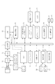
図2は、上記デジタルカメラの電気的構成の概略を示すブロック図である。上記デジタルカメラは静止画撮影と動画撮影とが可能であるとともに、コントラスト検出方式によるオートフォーカス(AF)、自動露出(AE)、自動白調整(AWB)、手振れ防止、顔認識の各種機能を有しており、以下の各部から構成される。 FIG. 2 is a block diagram showing an outline of the electrical configuration of the digital camera. The above digital camera can shoot still images and movies, and has various functions such as autofocus (AF), automatic exposure (AE), automatic white adjustment (AWB), camera shake prevention, and face recognition by contrast detection. It consists of the following parts.
すなわちデジタルカメラは前記撮像レンズ2の光軸上に配置された撮像手段であるCCD11を有している。前記撮像レンズ2はズームレンズやフォーカスレンズから構成されており、フォーカスレンズ及びズームレンズは、CPU16の指令に従いレンズドライバ17により生成される駆動信号によって駆動される。すなわちフォーカスレンズは、CPU16によるAF制御によってフォーカス位置に駆動され、また、ズームレンズは、ユーザーによるズームキーの操作に応じたズーム位置に駆動される。
That is, the digital camera has a
記録モードにおいてCCD11は、CPU16の制御に従いタイミングジェネレータ12によって生成される水平及び垂直駆動信号に基づき駆動され、被写体の光像を光電変換し撮像信号として出力する。CCD11の出力信号はCDS回路13で相関二重サンプリングされた後、A/D変換回路14でデジタル信号に変換される。A/D変換された撮像信号はDSP(Digital Signal Processor)15に入力され、ペデスタルクランプ等の処理が施された後、ブロック内の輝度・色差マトリックス回路でYUV変換によって輝度(Y)信号及び色差(UV)信号に変換される。また、DSP15は、CPU16の制御に従いオートホワイトバランス等の各種の画像処理を行う。
In the recording mode, the
DSP15から出力されたYUVデータは、1フレーム毎に順次内蔵メモリ18(例えばSDRAM)に格納され、内蔵メモリ18に格納された1フレーム分のYUVデータはCPU16により読み出される。その際には、所定の画像領域に対応するYUVデータのみの読み出しによる切り出し処理が必要に応じて行われる。
The YUV data output from the
内蔵メモリ18から読み出されたYUVデータは、必要に応じ解像度変換回路19において所定の画像サイズに拡大又は縮小、つまり変倍された後、表示コントローラ20でビデオ信号に変換され、LCD21によってスルー画像として表示される。
The YUV data read from the built-in
また、内蔵メモリ18から読み出された1フレーム分のYUVデータは、静止画撮影時においては前記データ圧縮伸長ブロック22でJPEG方式等でデータ圧縮符号化され、内蔵メモリ18内でファイル化された後、メディアコントローラ23を介して、カメラ本体1に装着された記録メディア24に静止画ファイルとして記録される。さらに、動画撮影時には、順次データ圧縮伸長ブロック22へ送られ、所定の動画記録方式(Motion−JPEGやMPEG等)のコーデックにより圧縮符号化された後、メディアコントローラ23を介して記録メディア24に動画ファイルとして逐次記録される。
The YUV data for one frame read from the built-in
一方、再生モードにおいてデータ圧縮伸長ブロック22は、記録メディア24から読み出された静止画ファイルや動画ファイルのデータを伸張し、静止画データや動画像のフレームデータとして内蔵メモリ18の画像データ作業領域に展開する。
On the other hand, in the playback mode, the data compression /
音声処理ブロック25は、音声付の動画撮影時においてカメラ本体1に内蔵されたマイク26に入力した音声をデジタル信号に変換し、データ圧縮後にオーディオデータとして内蔵メモリ18へ送る。内蔵メモリ18に送られたオーディオデータは、動画ファイルと共に記録メディア24に記録される。また、音声処理ブロック25は、音声付動画の再生時には、内蔵メモリ18から送られたオーディオデータを復号し、アナログの音声信号に変換した後、カメラ本体1に内蔵された内蔵スピーカ27から音声出力させる。
The
キー入力ブロック28は、前述したシャッターキー6、電源キー及び、記録モード、再生モードの各モードの切り替えを行うモード切替キー、ズームキー、MENUキー等の複数のスイッチ類を含み、使用者によるキー操作に応じたキー入力信号をCPU16に出力する。
The
手振れ検出部29は、デジタルカメラにおけるXY方向(上下左右方向)の加速度をそれぞれ検出する加速度センサと、そのセンサ出力をデジタル信号に変換するA/Dコンバータとを含み、デジタル信号に変換後のXY方向の加速度(手ぶれ検出信号)を手振れ量として検出しCPU16に出力し、本実施形態では本発明の取得手段として機能する。
The camera
ストロボ駆動部30は、キセノン管等の発光管、及び発光用コンデンサ、その充電回路、発光管の駆動回路を含み、CPU16からの命令に従い発光管を駆動し撮影補助光を発光する。
The
LED駆動部31は、前記LEDインジケータ5、及び前記動作確認用LED35と、それらを所定の色で発光させるための駆動制御回路とから構成され、CPU16からの命令に従いLEDインジケータ5と動作確認用LED35をデジタルカメラの動作確認用に予め決められている色で発光させ、また、LEDインジケータ5にAF補助光や撮影補助光を発光させる。
The
以上の各部はCPU16によって制御されており、CPU16に各部の制御を行わせるためのプログラムや、それに付随するデータはプログラムメモリ32に記憶されている。プログラムメモリ32はEEPROMやフラッシュメモリ等の書き換え可能な不揮発性メモリである。上記プログラム及びデータには、例えばCPU16にAE処理や、AF処理、顔認識処理等の各種の処理を行わせるためのプログラムやデータも含まれる。なお、顔認識処理は、スルー画像の表示中に逐次取得される画像データ(YUVデータ)に対して、二値化や輪郭抽出、パターンマッチング等を行い、画像内(画角内)に存在する、登録されている特定人物や、任意の人物の顔部分を検出する処理である。
Each unit described above is controlled by the
また、プログラムメモリ32には、上記プログラムやデータに加え、ユーザーにより設定、又は変更されたデジタルカメラに設けられている各種の機能に関する設定データも記憶されている。そして、CPU16は上記プログラム及びキー入力信号に基づき、上記設定データを参照しつつ各部を制御する。
The
一方、以上の構成からなる本実施形態のデジタルカメラには、記録モードの下位モードとして図3に示した種々の撮影モードを有している。すなわち記録モードは大別すると静止画撮影モードと動画撮影モードとの2種類であり、さらに、静止画撮影モードは大別すると通常、セルフタイマー、オートシャッター、連写(連続撮影)の4種類である。ここで、通常モードはAE、AF、AWBの各機能が有効な基本的な撮影モード、セルフタイマー・モードはシャッターキー6の全押し後、所定の設定時間が経過した時点で自動的に撮影が行われる一般的なモードである。また、オートシャッター・モードは、シャッターキー6の全押し後、手振れ度合(カメラ本体1の揺れ度合)が一定度合に収束した時点で自動的に撮影が行われるモード、連写モードはシャッターキー6の全押し後、全押し状態をキープしている間に一定間隔による複数回の撮影が連続して行われるモードである。 On the other hand, the digital camera according to the present embodiment having the above-described configuration has various shooting modes shown in FIG. 3 as lower modes of the recording mode. In other words, the recording modes are roughly divided into two types: a still image shooting mode and a moving image shooting mode. Furthermore, the still image shooting modes are roughly divided into four types: a self-timer, an auto shutter, and continuous shooting (continuous shooting). is there. Here, the normal mode is a basic shooting mode in which each function of AE, AF, and AWB is effective, and the self-timer mode is automatically shot when a predetermined set time elapses after the shutter key 6 is fully pressed. This is a common mode to be performed. The auto shutter mode is a mode in which shooting is automatically performed when the degree of camera shake (the degree of shaking of the camera body 1) converges to a certain degree after the shutter key 6 is fully pressed. The continuous shooting mode is the shutter key 6 In this mode, a plurality of times of shooting at a constant interval are continuously performed while the fully pressed state is kept after the button is fully pressed.
また、本実施形態のデジタルカメラにあっては、AFモードとして追尾モードと顔認識モードが用意されている。追尾モードは、シャッターキー6の半押操作に応答して特定の被写体部分にピントを合わせた後、半押操作が継続している間に、AF枠(ピント合わせの対象領域)の位置を上記被写体の動き等に追従させて自動的に移動させるモードである。また、顔認識モードは、シャッターキー6が半押しされる以前から、被写体内(画角内)に存在する、予め登録されている特定人物の顔部分や、任意の人物の顔部分を検出し、検出し顔部分にAF枠を自動的に設定するモードである。 In the digital camera of this embodiment, a tracking mode and a face recognition mode are prepared as AF modes. In the tracking mode, after a specific subject portion is focused in response to the half-pressing operation of the shutter key 6, the position of the AF frame (target area to be focused) is changed while the half-pressing operation continues. In this mode, the movement is automatically performed following the movement of the subject. Also, the face recognition mode detects a face portion of a specific person registered in advance in the subject (within the angle of view) or a face portion of an arbitrary person before the shutter key 6 is pressed halfway. In this mode, an AF frame is automatically set for the detected face portion.
そして、以上の構成からなるデジタルカメラにおいては、記録モードが設定されているとき、CPU16がプログラムメモリ32に記憶されているプログラムに従い、その時点で設定されている撮影モード及び設定されている各種の機能に対応した後述する処理を実行することにより本発明の撮影制御手段、点灯制御手段、判断手段、状況検出手段、表示制御手段として機能する。また、CPU16は、ユーザー操作に応じて撮影モードを選択して設定する処理を実行することにより本発明の撮影モード設定手段として機能する。
In the digital camera having the above-described configuration, when the recording mode is set, the
まず、CPU16による一連の撮影制御動作を説明する。
First, a series of photographing control operations by the
記録モードが設定されているとき、CPU16は、シャッターの半押し操作などに応じてAE処理(被写体の明るさに応じた自動露出制御)や、AF処理(被写体の距離に応じたオートフォーカス制御)、顔認識処理(AE処理、AF処理、自動撮影処理などの対象を人物の顔に設定するための処理)等の撮影準備動作を開始する。この撮影準備動作においては、後述するように、設定された撮影モードに応じて異なる動作を行う。そして、この撮影準備動作を実行しながら、または撮影準備動作を完了してから、後述するように、設定された撮影モードに応じた撮影開始条件が満たされるのを待機する。そして、この撮影開始条件が満たされると撮影記録動作を実行する。この撮影記録動作においては、撮像素子による撮像処理(露光動作)、撮像された画像の圧縮処理、圧縮された画像ファイルのメモリへの記録処理を行う。
When the recording mode is set, the
図4は、上記一連の撮影制御動作と並行して(連動して)CPU16により実行されるLED等の表示制御の処理内容を示したフローチャートである。すなわち記録モードにおいてCPU16は、前述したいずれかの撮影モードに対応した処理を実行しており、その間には、撮影モードの種類を含む各種機能に関する設定が変更されたか否かを逐次確認し、変更があれば(ステップS1でYES)、プログラムメモリ32に記憶されている設定データを変更内容に応じて書き換えることにより新たな設定内容を保存する(ステップS2)。そして設定が変更された場合には(ステップS3でYES)、直ちに変更後の撮影モードに対応した処理に移行する(ステップS4)。なお、機能設定は、ユーザーによるMENUキーの操作に応答してLCD21に各種のメニュー画面を表示させるとともに、ユーザーのキー操作に応じて行う。
FIG. 4 is a flowchart showing the processing contents of display control of the LED and the like executed by the
また、記録モードにおいてCPU16は、上記一連の撮影制御動作と並行して前述したLEDインジケータ5及び動作確認用LED35の点灯タイミングや、点灯パターンの変更タイミングが到来したか否かを逐次確認する。つまり、上記一連の撮影制御動作における撮影準備動作、撮影記録動作、撮像処理(露光動作)、圧縮処理、メモリへの記録処理、などの開始や完了などの処理状況を逐次確認する。そして、後述するように、各種撮影モード毎に予め決められているLEDの点灯パターンを示す情報に従って、現在の撮影モードにおいて、LEDの点灯状態を変化させるべき複数のタイミングのいずれかが到来したか否かを判断し、いずれかのタイミングが到来したときには(ステップS5でYES)、設定されている撮影モードおよび現在のタイミングに応じた所定の点灯パターンでLEDインジケータ5を点灯させる(ステップS6)。また、LCD21における撮影情報の表示タイミングが到来したか否かを逐次確認し、いずれかの表示タイミングが到来したときには(ステップS7でYES)、所定の撮影情報をLCD21に表示させる(ステップS8)。以後、同様の処理を繰り返し実行する。
In the recording mode, the
図5は、以上の処理を繰り返す間におけるデジタルカメラの撮影動作の内容と、各動作状態に対応したLEDインジケータ5及び動作確認用LED35の点灯の有無、及び点灯パターンと、LCD21に表示する撮影情報とを示した図である。この図で示されるように、撮影動作に応じたLEDの点灯パターンを示す情報は、各種撮影モード毎に予め記憶されており、上述した撮影制御動作と連動したLEDの表示制御処理において、LEDの点灯状態を変化させるべきタイミングを判断する際に参照される。
FIG. 5 shows the contents of the photographing operation of the digital camera, the presence / absence of lighting of the LED indicator 5 and the
LEDインジケータ5の点灯タイミングと点灯パターンは以下の通りである。すなわち点灯タイミングは、主としてAF動作に関するタイミングと、撮影動作に関するタイミングと、その他のタイミングである。そのうちAF動作に関するタイミングとしては、静止画撮影モードでのAF動作の開始時点、及びAFモードとして追尾モードが設定されている場合においてAF枠が移動限界に達した時点である。また、撮影動作に関するタイミングとしては、露光終了後の各処理(NR(ノイズリダクション)、画像処理、JPEGエンコード)の開始時点と、動画撮影モードでの撮影開始時点(動画データの記録開始時点)である。また、その他のタイミングとしては、セルフタイマー・モードでの撮影タイミングのカウントダウン開始時点、及び残り時間が5秒及び2秒となった時点と、オートシャッター・モードでのシャッターキー6の全押し後において、手振れ度合が「大」、「中」、「小」となった時点である。 The lighting timing and lighting pattern of the LED indicator 5 are as follows. That is, the lighting timing is mainly the timing related to the AF operation, the timing related to the photographing operation, and other timings. Among them, the timing related to the AF operation is the start time of the AF operation in the still image shooting mode and the time when the AF frame reaches the movement limit when the tracking mode is set as the AF mode. Also, the timing related to the shooting operation is the start time of each process (NR (noise reduction), image processing, JPEG encoding) after the exposure and the start time of shooting in the video shooting mode (video data recording start time). is there. In addition, as other timings, the shooting timing countdown start time in the self-timer mode, the remaining time becomes 5 seconds and 2 seconds, and after the shutter key 6 is fully pressed in the auto shutter mode. This is the time when the degree of camera shake becomes “large”, “medium”, and “small”.
一方、点灯パターンは、所定色(本実施形態では赤色のみ)での継続点灯を含むとともに、点灯色と点滅速度と点灯回数との組合せによるものであって、点滅速度としては、図6(a)に示した0.5秒毎(1Hz)の第1の点滅速度(点滅1)と、同図(b)に示した0.25秒毎(2Hz)の第2の点滅速度(点滅2)と、同図(c)に示した0.125秒毎(4Hz)の第3の点滅速度(点滅3)と3種類であり、点灯色は緑色のみ、赤色のみ、緑色と赤色の交互の3種類である。 On the other hand, the lighting pattern includes continuous lighting in a predetermined color (only red in the present embodiment) and is a combination of the lighting color, the flashing speed, and the number of lightings. ) First flashing rate (flashing 1) every 0.5 seconds (1 Hz) shown in FIG. 5 and second flashing rate (flashing 2) every 0.25 seconds (2 Hz) shown in FIG. And the third blinking speed (blinking 3) of 0.125 seconds (4 Hz) shown in FIG. 3C, and the three types, and the lighting color is only green, only red, and alternately green and red 3 It is a kind.
なお、動作確認用LED35の点灯タイミングや点灯パターン、及びLCD21における撮影情報の表示タイミングと、表示する撮影情報については詳細な説明を省略するが、動作確認用LED35については、点灯色が緑のみであるとともに、図示したタイミングで前述した第1〜第3の点滅速度により点滅させたり、継続点灯させたりする。また、LCD21に表示させる撮影情報は、緑又は赤のAF枠や、シャッタースピード等の数値の橙色での表示、RECアイコンの表示、撮影タイミングまでのカウントダウン時間等であり、それらの表示タイミングは図示した通りである。
Although detailed description of the lighting timing and lighting pattern of the
次に、上述したLEDインジケータ5における撮影モードに応じたより具体的な点灯タイミング及び点灯パターンの例を図7〜図10のタイミングチャートに従い説明する。 Next, more specific examples of lighting timings and lighting patterns corresponding to the shooting modes in the LED indicator 5 will be described with reference to the timing charts of FIGS.
図7は、静止画撮影モードのうち通常モードが設定されているとともに、必要に応じたAF補助光の使用が設定されている場合のタイミングチャートである。この場合、図示したようにCPU16は、シャッターキー6の半押し操作に応答して開始したAE及びAWB処理が完了した時点で、被写体の明るさに基づきAF補助光のオンオフ(要否)を判定し、そのタイミング(T1)で、AF補助光が必要と判定した場合にはLEDインジケータ5を緑色の最高輝度で点灯させ、同時にAF制御を開始する。その後、合焦状態が確認できたタイミング(T2)で、LEDインジケータ5の点灯パターンを緑色と赤色とによる第3の点滅速度(点滅3)での交互点滅に切り替える。これにより、被写体となっている者に対してカメラが具体的な撮影準備に入ったこと、つまり実際の撮影がいつ行われてもおかしくない状態となったことを知らせる。
FIG. 7 is a timing chart when the normal mode is set in the still image shooting mode and the use of AF auxiliary light is set as necessary. In this case, as shown in the figure, the
また、AF補助光のオンオフ判定が完了したタイミング(T1)でAF補助光が不用と判断した場合には、直ちにLEDインジケータ5を緑色と赤色とによって第3の点滅速度で交互に点灯させ、これにより、被写体となっている者に対してカメラが具体的な撮影準備に入ったことを知らせ、同時にAF制御を開始する。以後、上記パターによる点灯を継続し、シャッターキー6が全押しされたタイミング(T3)でLEDインジケータ5をいったん消灯させ、同時に露光を開始した後、露光が完了したタイミング(T4)でLEDインジケータ5を緑色によって第3の点滅速度で2回点滅させる。これにより、被写体となっている者に撮影完了を知らせる。 Further, when it is determined that the AF auxiliary light is unnecessary at the timing (T1) when the AF auxiliary light on / off determination is completed, the LED indicator 5 is immediately turned on alternately in green and red at the third blinking speed. Thus, the person who is the subject is informed that the camera has entered a specific shooting preparation, and at the same time, AF control is started. Thereafter, the lighting by the putter is continued, the LED indicator 5 is once turned off at the timing (T3) when the shutter key 6 is fully pressed, the exposure is started at the same time, and the LED indicator 5 at the timing (T4) when the exposure is completed. Is flashed twice in green at a third flash rate. This notifies the person who is the subject of the completion of shooting.
なお、上述したタイミングに加え、AFモードとして前述した顔認識モードや追尾モードが設定されている場合においては、以下のタイミングにおいてもLEDインジケータ5を点灯する。すなわち顔認識モードが設定されている場合には、図8(a)に示したように、CPU16はシャッターキー6が半押しされる以前から、特定人物や任意の人物の顔部分を検出し、検出し顔部分にAF枠を自動的に設定する一方、その間にはAF枠が予め決められている移動限界に達しているか否かを逐次確認し、AF枠が移動限界に達したと判断したタイミング(T5)でLEDインジケータ5を赤色により第1の点滅速度(点滅1)で2回点滅させる。以後、シャッターキー6が半押しされるまでは、AF枠が移動限界に達していると判断する毎に、LEDインジケータ5を上記点灯パターンで点灯させる。これにより、撮影時には、自分が立ち位置を変える際には、どこまで移動してもよいのかを被写体となっている者に知らせる。
In addition to the timing described above, when the above-described face recognition mode or tracking mode is set as the AF mode, the LED indicator 5 is also lit at the following timing. That is, when the face recognition mode is set, as shown in FIG. 8A, the
また、顔認識モードが設定されている場合には、図8(b)に示したように、CPU16は前述したようにAF動作で合焦状態が確認できたタイミング(T2)でLEDインジケータ5における緑色と赤色とによる第3の点滅速度での交互点灯を開始した後、ピントを合わせた特定の被写体部分の動き等に追従させてAF枠の位置を自動的に移動させるとともに、その間にAF枠が予め決められている移動限界に達しているか否かを逐次確認し、AF枠の位置が移動限界に達したと判断したタイミング(T6)でLEDインジケータ5を赤色により第1の点滅速度(点滅1)で2回点滅させる。以後、シャッターキー6が全押しされるまでは、AF枠が移動限界に達したと判断する毎に、LEDインジケータ5を上記点灯パターンで点灯させる。これにより、撮影時には、自分が立ち位置を変える際には、どこまで移動してもよいのかを被写体となっている者に知らせる。
When the face recognition mode is set, as shown in FIG. 8 (b), the
一方、図9(a)は、静止画撮影モードのうちオートシャッター・モードが設定されている場合のタイミングチャートである。この場合、図示したようにCPU16は、シャッターキー6が全押しされたタイミング(T3)で、LEDインジケータ5における緑色による第1の点滅速度(点滅1)での点滅点灯を開始する。なお、図では省略したがシャッターキー6が全押しされる以前は図7に示した通常モードと同様である。また、CPU16は上記LEDインジケータ5の点滅開始と同時に手振れ量の検出を開始する。その後、図9(b)に示したように、逐次検出される手ブレ度合を予め決められている判定基準に従い大、中、小の3段階で判定するとともに、手ブレ度合が「大」であると判断される間は点灯パターンを第1の点滅速度(点滅1)による点滅点灯とし、「中」であると判断される間は点灯パターンを第2の点滅速度(点滅2)による点滅点灯とし、「小」であると判断される間は点灯パターンを第3の点滅速度(点滅3)による点滅点灯とする。やがて、手振れが収束したと判断できる状態となった時点、つまり閾値以下の手振れ量を検出したシャッターチャンス検出タイミング(T7)でLEDインジケータ5を消灯し、自動的に露光を開始する。これ以後は、図7に示した通常モードと同様である。
On the other hand, FIG. 9A is a timing chart when the auto shutter mode is set in the still image shooting mode. In this case, as shown in the figure, the
また、図10(a)は、セルフタイマー・モードが設定されている場合のタイミングチャートである。この場合、図示したようにCPU16は、シャッターキー6が全押しされたタイミング(T3)で、予め設定されている所定時間(ここでは10秒)のカウントダウンを開始すると同時にLEDインジケータ5を赤色による第1の点滅速度(点滅1)での点滅点灯を開始する。その後、図10(b)に示したように、残りのカウント時間が5秒までの間は上記の点灯パターンでの点灯を継続し、その後、残りのカウント時間が2秒となった時点で、点灯パターンを第2の点滅速度(点滅2)による点滅点灯に切り替え、さらに残りのカウント時間が2秒となったタイミング(T8)で、緑色と赤色とによる第3の点滅速度での交互点灯に切り替える。そして、シャッターキー6が全押しされてから10秒が経過しカウント時間が0秒となったタイミング(T9)でLEDインジケータ5を消灯する。
FIG. 10A is a timing chart when the self-timer mode is set. In this case, as shown in the figure, the
したがって、セルフタイマー・モードでの撮影時において被写体となっている者は、LEDインジケータ5の点灯パターンの変化によって、撮影2秒前のタイミング(T7)を確実に知ることができる。 Therefore, a person who is a subject at the time of shooting in the self-timer mode can surely know the timing (T7) two seconds before shooting by changing the lighting pattern of the LED indicator 5.
また、図示しないが静止画撮影モードのうち連写モードが設定されている場合には、図7に示した通常モードの場合と同様に、AF補助光のオンオフ判定が完了したタイミング(T1)又は合焦状態が確認できたタイミング(T2)で、EDインジケータ5を緑色と赤色とにより第3の点滅速度で交互に点灯させるとともに、シャッターキー6が全押しされたタイミングでEDインジケータ5を消灯させる。その後は、消灯状態を維持したまま、シャッターキー6が全押しされている間に一定間隔による複数回の撮影を連続して行い、シャッターキー6の全押しが解除された直後における最後の露光動作が終了したタイミングで、でLEDインジケータ5を緑色によって第3の点滅速度で2回点滅させ、それにより、被写体となっている者に撮影完了を知らせる。 Although not shown, when the continuous shooting mode is set in the still image shooting mode, as in the normal mode shown in FIG. 7, the timing (T1) when the AF auxiliary light ON / OFF determination is completed or At the timing (T2) when the in-focus state is confirmed, the ED indicator 5 is alternately turned on at a third blinking speed by green and red, and the ED indicator 5 is turned off when the shutter key 6 is fully pressed. . After that, the last exposure operation immediately after the full release of the shutter key 6 is released by continuously performing a plurality of shootings at a fixed interval while the shutter key 6 is fully pressed while maintaining the light-off state. At the timing when is completed, the LED indicator 5 blinks twice at a third blinking speed in green, thereby notifying the person who is the subject of the completion of photographing.
また、図示しないが動画撮影モードによる動画撮影時(ムービー録画中)には、図5に示したように、撮影開始から撮影終了までの全期間中にLEDインジケータ5を赤色によって点灯し続ける。さらに、動画撮影中には、任意の時点でシャッターキー6の操作に応答し静止画撮影に向けた動作を行い、その動作に際しては、シャッターキー6の半押し後に図7に示した通常モードの場合と同様のタイミング(T1)〜(T4)においてLEDインジケータ5を既説した点灯パターンによりそれぞれ点灯させる。 Although not shown, during moving image shooting in the moving image shooting mode (during movie recording), as shown in FIG. 5, the LED indicator 5 continues to be lit in red during the entire period from the start of shooting to the end of shooting. Furthermore, during moving image shooting, an operation for shooting a still image is performed in response to the operation of the shutter key 6 at an arbitrary time point. In this operation, the normal mode shown in FIG. At the same timings (T1) to (T4) as in the case, the LED indicator 5 is turned on by the lighting pattern described above.
以上のように本実施形態のデジタルカメラにおいては、撮影動作中にLEDインジケータ5の点灯パターンを前述したように変化させることにより、現在、カメラが撮影準備(撮影待機)、撮影予告(撮影開始)、撮影完了へと順に遷移する一連の動作状態のどの状態にあるのかを被写体となっている者に知らせることができる。 As described above, in the digital camera according to the present embodiment, by changing the lighting pattern of the LED indicator 5 during the photographing operation as described above, the camera is currently preparing for photographing (standby for photographing) and shooting notice (starting photographing). It is possible to notify the person who is the subject of which state of the series of operation states that sequentially shift to the completion of photographing.
そして、LEDインジケータ5の各動作状態に対応した点灯パターンを撮影モードに応じて異なる点灯パターンとした。これにより、被写体となっている者に対して撮影時におけるカメラの動作状態を知らせると同時に、現在設定されている撮影モードがいずれの撮影モードであるか、すなわち撮影タイミングの決定方法としていずれの方法が採用されているのかを識別させることができる。したがって、撮影モードの違いに応じて撮影時における動作状態の遷移パターンが変化する場合であっても、被写体となっている者に対し、実際の撮影タイミングをより正確に教えることができる。その結果、撮影される側における撮影に向けた準備期間を必要且つ最小限に止めることができ、被写体となっている者の負担を軽減することができる。 And the lighting pattern corresponding to each operation state of the LED indicator 5 was made into the lighting pattern which changes according to imaging | photography mode. As a result, the operating state of the camera at the time of shooting is notified to the person who is the subject, and at the same time, which shooting mode is currently set, that is, which method is used as a method for determining the shooting timing Can be identified. Therefore, even when the transition pattern of the operation state at the time of shooting changes depending on the shooting mode, the actual shooting timing can be more accurately taught to the person who is the subject. As a result, the preparation period for shooting on the shooting side can be minimized and necessary, and the burden on the person who is the subject can be reduced.
ここで、本実施形態においては、LEDインジケータ5の点灯パターンを動作状態に応じて変化させることにより、被写体となっている者が点灯パターンによって現在の動作状態を識別できるようにしたが、これに限らず、動作状態中における実際の撮影動作つまり露光開始動作の直前の動作状態となったタイミング、例えば通常モードであれば、合焦状態が確認できたタイミング(図7でT2)に、LEDインジケータ5を撮影モードを表す特定の点灯パターンで点灯させるだけとしてもよい。その場合であっても、被写体となっている者に対し、撮影モードの違いなどによって変化する実際の撮影タイミングをより正確に教えることができる。 Here, in the present embodiment, the lighting pattern of the LED indicator 5 is changed according to the operating state, so that the person who is the subject can identify the current operating state by the lighting pattern. The LED indicator is not limited to the timing when the actual shooting operation in the operation state, that is, the operation state immediately before the exposure start operation, for example, in the normal mode, the timing when the in-focus state can be confirmed (T2 in FIG. 7). 5 may be lit only with a specific lighting pattern representing the photographing mode. Even in such a case, the person who is the subject can be taught more accurately the actual shooting timing that changes due to a difference in shooting mode or the like.
また、本実施形態においては、LEDインジケータ5の点灯パターンを点灯色と点滅速度(3種類)と点灯回数との組合せによるものとしたが、それの要素のいずれか1つのみを用いて複数の点灯パターンを構成させるようにしてもよい。 Further, in the present embodiment, the lighting pattern of the LED indicator 5 is based on the combination of the lighting color, the blinking speed (three types), and the number of times of lighting. However, a plurality of patterns using only one of the elements is used. You may make it comprise a lighting pattern.
また、動作状態や撮影モード(の種類)に対応する点灯パターンを周囲の明るさに応じて変化させてもよい。例えば各々の点灯パターンとして周囲が明るいときに識別しやすい中間用の点灯パターンと、周囲が暗いときに識別しやすい夜間用の点灯パターンとを用意しておき、撮影動作時には、カメラ本体の周囲の明るさをAE制御に際して取得した被写体の明るさ等に基づき検出し、その検出結果に応じて点灯パターンとして中間用の点灯パターン又は夜間用の点灯パターンを選択的に使用するようにしてもよい。 Further, the lighting pattern corresponding to the operation state and the shooting mode (type) may be changed according to the ambient brightness. For example, prepare an intermediate lighting pattern that is easy to identify when the surroundings are bright and a night lighting pattern that is easy to identify when the surroundings are dark as each lighting pattern. The brightness may be detected based on the brightness of the subject acquired during the AE control, and an intermediate lighting pattern or a night lighting pattern may be selectively used as a lighting pattern according to the detection result.
また、LEDインジケータ5が必要に応じてAF補助光や撮影補助光の光源としても使用されるものについて説明したが、LEDインジケータ5が撮影動作中の動作状態や撮影モードといった撮影時における動作情報を被写体となっている者に提供する機能のみを有する構成としても構わない。 In addition, the LED indicator 5 is used as a light source for AF auxiliary light or photographing auxiliary light as necessary. However, the operation information during photographing such as the operation state and photographing mode during the photographing operation of the LED indicator 5 is described. A configuration having only a function provided to the person who is the subject may be used.
また、光学ファインダ4の内部の動作確認用LED35によって撮影者に知らせる撮影動作中における現在の動作状態と、LEDインジケータ5によって被写体となっている者に知らせる撮影動作中における現在の動作状態とが一致していない、つまりCPU16が動作確認用LED35の点灯動作と、LEDインジケータ5の点灯動作とを連動させない点灯制御を行う構成としたが(図5参照)、CPU16が両者の点灯動作を連動させる点灯制御を行う構成としてもよい。
Also, the current operation state during the photographing operation that informs the photographer by the
また、LEDインジケータ5をカメラ本体1の正面に設けたが、LEDインジケータ5は画角内の任意の位置から視認可能な位置であれば他の位置に設けても構わないし、また、LEDインジケータ5は他の発光素子に代えても構わない。 Although the LED indicator 5 is provided on the front surface of the camera body 1, the LED indicator 5 may be provided at other positions as long as the LED indicator 5 is visible from an arbitrary position within the angle of view. May be replaced with other light emitting elements.
また、ここでは本発明をデジタルカメラに適用した場合について説明したが、これに限らず本発明は、カメラ付き携帯電話機や、カメラ機能を有するその他の携帯情報機器にも適用することができる。 Although the case where the present invention is applied to a digital camera has been described here, the present invention is not limited thereto, and the present invention can also be applied to a camera-equipped mobile phone and other portable information devices having a camera function.
1 カメラ本体
4 光学ファインダ
5 LEDインジケータ
6 シャッターキー
11 CCD
16 CPU
18 内蔵メモリ
20 表示コントローラ
21 LCD
28 キー入力ブロック
29 手振れ検出部
31 LED駆動部
32 プログラムメモリ
1
16 CPU
18 Built-in
28
Claims (12)
撮影時に変化する基準情報の内容が予め決められた自動撮影の条件に該当する内容に変化した時点で自動的に撮影を行うとともに前記基準情報の変化に応じて前記発光素子の点灯パターンを順次変化させる自動撮影に関し、撮影指示からの経過時間を前記基準情報とする第1の撮影モードと、画像の振れ量を前記基準情報とするとともに前記点灯パターンを順次変化させる変化方法が前記第1の撮影モードとは異なる第2の撮影モードとを含む複数の撮影モードのいずれかを選択的に設定する撮影モード設定手段と、
前記撮影モード設定手段により撮影モードが設定された後、自動露出制御、オートフォーカス制御、顔認識処理のうちの少なくとも1つを含む撮影準備動作を開始するとともに、撮影指示があると、前記撮影モード設定手段により設定された撮影モードに応じた基準情報の内容が該撮影モードに応じた自動撮影の条件を満たすまで待機し、該自動撮影の条件が満たされた後に撮影記録を行う一連の自動撮影動作を実行する撮影制御手段と、
撮影制御手段により実行される前記一連の自動撮影動作に際し、撮影準備動作における所定のタイミングで所定の点灯パターンによって前記発光素子を点灯させるとともに、撮影指示があってから自動撮影の条件が満たされるまでの間、前記発光素子の点灯パターンを、前記撮影モード設定手段により設定された撮影モードに対応する前記変化方法により、前記基準情報の変化に応じて順次変化させる点灯制御手段と
を備えたことを特徴とするカメラ装置。 A light emitting element provided at a position visible from an arbitrary position within the angle of view in the apparatus body;
When the content of the reference information that changes at the time of shooting changes to a content that meets a predetermined automatic shooting condition, shooting is automatically performed, and the lighting pattern of the light emitting element is sequentially changed according to the change of the reference information In relation to automatic shooting, a first shooting mode in which an elapsed time from a shooting instruction is used as the reference information, and a change method in which an image shake amount is used as the reference information and the lighting pattern is sequentially changed are the first shooting. A shooting mode setting means for selectively setting one of a plurality of shooting modes including a second shooting mode different from the mode;
After the shooting mode is set by the shooting mode setting means, a shooting preparation operation including at least one of automatic exposure control, autofocus control, and face recognition processing is started. A series of automatic photographing that waits until the content of the reference information according to the photographing mode set by the setting means satisfies the conditions of automatic photographing according to the photographing mode, and performs photographing recording after the automatic photographing conditions are satisfied Photographing control means for performing the operation;
During the series of automatic photographing operations executed by the photographing control means, the light emitting element is turned on by a predetermined lighting pattern at a predetermined timing in the photographing preparation operation, and after the photographing instruction is given until the automatic photographing condition is satisfied And a lighting control means for sequentially changing the lighting pattern of the light emitting element according to the change of the reference information by the changing method corresponding to the shooting mode set by the shooting mode setting means. A camera device.
前記第2の撮影モードは、画像の振れ量が閾値以下となった時点が撮影タイミングとして決定する撮影モードであることを特徴とする請求項1乃至3いずれか記載のカメラ装置。 The reference information is an image shake amount,
4. The camera device according to claim 1, wherein the second shooting mode is a shooting mode in which a time point at which an image shake amount is equal to or less than a threshold is determined as a shooting timing. 5.
前記点灯制御手段は、動画撮影期間中に実施される静止画撮影を目的とした自動撮影動作に際しても、当該自動撮影動作中に順に遷移する一連の動作状態に応じて前記発光素子の点灯を制御するとともに、当該点灯制御に伴い前記発光素子を前記特定の点灯パターンで点灯させることを特徴とする請求項1乃至5いずれか記載のカメラ装置。 In addition to having a video shooting function, the automatic shooting operation is an automatic shooting operation for still image shooting,
The lighting control means controls the lighting of the light emitting element according to a series of operation states that sequentially shift during the automatic shooting operation even in the automatic shooting operation for the purpose of still image shooting performed during the moving image shooting period. The camera device according to claim 1, wherein the light emitting element is lit in the specific lighting pattern in accordance with the lighting control.
前記自動撮影動作に際し、当該自動撮影動作に含まれる一連の動作状態を前記表示手段に表示させる動作情報表示手段と、
をさらに備えたことを特徴とする請求項1乃至6いずれか記載のカメラ装置。 Display means for displaying an image captured by the imaging means;
In the automatic photographing operation, operation information display means for displaying a series of operation states included in the automatic photographing operation on the display means;
The camera apparatus according to claim 1, further comprising:
撮影時に変化する基準情報の内容が予め決められた自動撮影の条件に該当する内容に変化した時点で自動的に撮影を行うとともに前記基準情報の変化に応じて前記発光素子の点灯パターンを順次変化させる自動撮影に関し、撮影指示からの経過時間を前記基準情報と
する第1の撮影モードと、画像の振れ量を前記基準情報とするとともに前記点灯パターンを順次変化させる変化方法が前記第1の撮影モードとは異なる第2の撮影モードとを含む複数の撮影モードのいずれかを選択的に設定する撮影モード設定処理と、
前記撮影モード設定処理により撮影モードが設定された後、自動露出制御、オートフォーカス制御、顔認識処理のうちの少なくとも1つを含む撮影準備動作を開始するとともに、撮影指示があると、前記撮影モード設定処理により設定された撮影モードに応じた基準情報の内容が該撮影モードに応じた自動撮影の条件を満たすまで待機し、該自動撮影の条件が満たされた後に撮影記録を行う一連の自動撮影動作を実行する撮影制御処理と、
撮影制御処理により実行される前記一連の自動撮影動作に際し、撮影準備動作における所定のタイミングで所定の点灯パターンによって前記発光素子を点灯させるとともに、撮影指示があってから自動撮影の条件が満たされるまでの間、前記発光素子の点灯パターンを、前記撮影モード設定処理により設定された撮影モードに対応する前記変化方法により、前記基準情報の変化に応じて順次変化させる点灯制御処理と
を含むことを特徴とする撮影タイミング報知方法。 A shooting timing notification method in a camera device in which a light emitting element is provided at a position that is visible from an arbitrary position within an angle of view in the apparatus body,
When the content of the reference information that changes at the time of shooting changes to a content that meets a predetermined automatic shooting condition, shooting is automatically performed, and the lighting pattern of the light emitting element is sequentially changed according to the change of the reference information In relation to automatic shooting, a first shooting mode in which an elapsed time from a shooting instruction is used as the reference information, and a change method in which an image shake amount is used as the reference information and the lighting pattern is sequentially changed are the first shooting. A shooting mode setting process for selectively setting one of a plurality of shooting modes including a second shooting mode different from the mode;
After the shooting mode is set by the shooting mode setting process, a shooting preparation operation including at least one of automatic exposure control, autofocus control, and face recognition processing is started, and when there is a shooting instruction, the shooting mode is A series of automatic shooting that waits until the content of the reference information according to the shooting mode set by the setting process satisfies the conditions of automatic shooting according to the shooting mode, and performs shooting recording after the automatic shooting conditions are satisfied A shooting control process for performing the operation;
In the series of automatic photographing operations executed by the photographing control process, the light emitting element is turned on by a predetermined lighting pattern at a predetermined timing in the photographing preparation operation, and until the automatic photographing condition is satisfied after the photographing instruction is given. A lighting control process of sequentially changing the lighting pattern of the light emitting element according to the change of the reference information by the changing method corresponding to the shooting mode set by the shooting mode setting process. An imaging timing notification method.
撮影時に変化する基準情報の内容が予め決められた自動撮影の条件に該当する内容に変化した時点で自動的に撮影を行うとともに前記基準情報の変化に応じて前記発光素子の点灯パターンを順次変化させる自動撮影に関し、撮影指示からの経過時間を前記基準情報とする第1の撮影モードと、画像の振れ量を前記基準情報とするとともに前記点灯パターンを順次変化させる変化方法が前記第1の撮影モードとは異なる第2の撮影モードとを含む複数の撮影モードのいずれかを選択的に設定する撮影モード設定手段と、
前記撮影モード設定手段により撮影モードが設定された後、自動露出制御、オートフォーカス制御、顔認識処理のうちの少なくとも1つを含む撮影準備動作を開始するとともに、撮影指示があると、前記撮影モード設定手段により設定された撮影モードに応じた基準情報の内容が該撮影モードに応じた自動撮影の条件を満たすまで待機し、該自動撮影の条件が満たされた後に撮影記録を行う一連の自動撮影動作を実行する撮影制御手段と、
撮影制御手段により実行される前記一連の自動撮影動作に際し、撮影準備動作における所定のタイミングで所定の点灯パターンによって前記発光素子を点灯させるとともに、撮影指示があってから自動撮影の条件が満たされるまでの間、前記発光素子の点灯パターンを、前記撮影モード設定手段により設定された撮影モードに対応する前記変化方法により、前記基準情報の変化に応じて順次変化させる点灯制御手段と
して機能させることを特徴とする撮影タイミング報知プログラム。 A computer having a camera device in which a light emitting element is provided at a position that is visible from an arbitrary position within an angle of view in the apparatus main body;
When the content of the reference information that changes at the time of shooting changes to a content that meets a predetermined automatic shooting condition, shooting is automatically performed, and the lighting pattern of the light emitting element is sequentially changed according to the change of the reference information In relation to automatic shooting, a first shooting mode in which an elapsed time from a shooting instruction is used as the reference information, and a change method in which an image shake amount is used as the reference information and the lighting pattern is sequentially changed are the first shooting. A shooting mode setting means for selectively setting one of a plurality of shooting modes including a second shooting mode different from the mode;
After the shooting mode is set by the shooting mode setting means, a shooting preparation operation including at least one of automatic exposure control, autofocus control, and face recognition processing is started. A series of automatic photographing that waits until the content of the reference information according to the photographing mode set by the setting means satisfies the conditions of automatic photographing according to the photographing mode, and performs photographing recording after the automatic photographing conditions are satisfied Photographing control means for performing the operation;
During the series of automatic photographing operations executed by the photographing control means, the light emitting element is turned on by a predetermined lighting pattern at a predetermined timing in the photographing preparation operation, and after the photographing instruction is given until the automatic photographing condition is satisfied During this time, the lighting pattern of the light emitting element is caused to function as a lighting control unit that sequentially changes according to the change of the reference information by the changing method corresponding to the shooting mode set by the shooting mode setting unit. An imaging timing notification program characterized by the above.
Priority Applications (1)
| Application Number | Priority Date | Filing Date | Title |
|---|---|---|---|
| JP2008273674A JP5889507B2 (en) | 2008-10-24 | 2008-10-24 | Camera device, shooting timing notification method, shooting timing notification program |
Applications Claiming Priority (1)
| Application Number | Priority Date | Filing Date | Title |
|---|---|---|---|
| JP2008273674A JP5889507B2 (en) | 2008-10-24 | 2008-10-24 | Camera device, shooting timing notification method, shooting timing notification program |
Publications (3)
| Publication Number | Publication Date |
|---|---|
| JP2010102132A JP2010102132A (en) | 2010-05-06 |
| JP2010102132A5 JP2010102132A5 (en) | 2011-11-24 |
| JP5889507B2 true JP5889507B2 (en) | 2016-03-22 |
Family
ID=42292830
Family Applications (1)
| Application Number | Title | Priority Date | Filing Date |
|---|---|---|---|
| JP2008273674A Expired - Fee Related JP5889507B2 (en) | 2008-10-24 | 2008-10-24 | Camera device, shooting timing notification method, shooting timing notification program |
Country Status (1)
| Country | Link |
|---|---|
| JP (1) | JP5889507B2 (en) |
Families Citing this family (2)
| Publication number | Priority date | Publication date | Assignee | Title |
|---|---|---|---|---|
| JP5745951B2 (en) * | 2011-06-27 | 2015-07-08 | 京セラ株式会社 | Photography equipment |
| JP7057300B2 (en) * | 2019-02-22 | 2022-04-19 | ファナック株式会社 | Control system |
Family Cites Families (6)
| Publication number | Priority date | Publication date | Assignee | Title |
|---|---|---|---|---|
| JPH03175433A (en) * | 1989-12-05 | 1991-07-30 | Olympus Optical Co Ltd | Automatic focusing type camera |
| JP2002328408A (en) * | 2001-04-26 | 2002-11-15 | Olympus Optical Co Ltd | Camera |
| JP2003186081A (en) * | 2001-10-09 | 2003-07-03 | Konica Corp | Camera |
| JP2006126769A (en) * | 2004-09-29 | 2006-05-18 | Fuji Photo Film Co Ltd | Camera |
| JP2006178201A (en) * | 2004-12-22 | 2006-07-06 | Fuji Photo Film Co Ltd | Imaging apparatus |
| JP2007304126A (en) * | 2006-05-08 | 2007-11-22 | Fujifilm Corp | Photographing device |
-
2008
- 2008-10-24 JP JP2008273674A patent/JP5889507B2/en not_active Expired - Fee Related
Also Published As
| Publication number | Publication date |
|---|---|
| JP2010102132A (en) | 2010-05-06 |
Similar Documents
| Publication | Publication Date | Title |
|---|---|---|
| JP4761146B2 (en) | Imaging apparatus and program thereof | |
| JP4338047B2 (en) | Imaging device | |
| US10542216B2 (en) | Apparatus and method for storing moving image portions | |
| JPWO2009013850A1 (en) | Imaging device | |
| US8934039B2 (en) | External equipment storing manipulation information and operation information and camera system using such information | |
| JP2009251658A (en) | Portable electronic equipment and control method thereof | |
| JP2006238076A (en) | Photographic apparatus | |
| JP2007324877A (en) | Imaging device | |
| JP2009239923A (en) | Imaging device | |
| JP2008054177A (en) | Imaging apparatus | |
| JP2005236509A (en) | Digital camera | |
| JP4381053B2 (en) | Imaging device | |
| JP2003244487A (en) | Digital camera and image display device | |
| JP4687542B2 (en) | Imaging apparatus, imaging method, and program | |
| JP5889507B2 (en) | Camera device, shooting timing notification method, shooting timing notification program | |
| JP2009080458A (en) | Imaging device and imaging method | |
| JP4717840B2 (en) | Imaging apparatus and control method thereof | |
| JP2005079915A (en) | Portable device with camera, and image pickup method thereof | |
| JP2007028546A (en) | Imaging apparatus | |
| JP2006330211A (en) | Camera, camera control program and camera control method | |
| JP2006165600A (en) | Photographing apparatus | |
| JP2008227925A (en) | Photographing apparatus and lighting control method for back light | |
| JP2006222900A (en) | Imaging device and control program therefor | |
| JP2006191234A (en) | Imaging apparatus, operation state presentation method, and operation state presentation program | |
| JP2008236712A (en) | Electronic device and setting switching method thereof, image reproducing method, and operation control method |
Legal Events
| Date | Code | Title | Description |
|---|---|---|---|
| A521 | Request for written amendment filed |
Free format text: JAPANESE INTERMEDIATE CODE: A523 Effective date: 20111004 |
|
| A621 | Written request for application examination |
Free format text: JAPANESE INTERMEDIATE CODE: A621 Effective date: 20111004 |
|
| A977 | Report on retrieval |
Free format text: JAPANESE INTERMEDIATE CODE: A971007 Effective date: 20130325 |
|
| A131 | Notification of reasons for refusal |
Free format text: JAPANESE INTERMEDIATE CODE: A131 Effective date: 20130402 |
|
| A521 | Request for written amendment filed |
Free format text: JAPANESE INTERMEDIATE CODE: A523 Effective date: 20130528 |
|
| A02 | Decision of refusal |
Free format text: JAPANESE INTERMEDIATE CODE: A02 Effective date: 20130910 |
|
| A521 | Request for written amendment filed |
Free format text: JAPANESE INTERMEDIATE CODE: A523 Effective date: 20131205 |
|
| A911 | Transfer to examiner for re-examination before appeal (zenchi) |
Free format text: JAPANESE INTERMEDIATE CODE: A911 Effective date: 20131213 |
|
| A912 | Re-examination (zenchi) completed and case transferred to appeal board |
Free format text: JAPANESE INTERMEDIATE CODE: A912 Effective date: 20140131 |
|
| A521 | Request for written amendment filed |
Free format text: JAPANESE INTERMEDIATE CODE: A523 Effective date: 20150128 |
|
| A521 | Request for written amendment filed |
Free format text: JAPANESE INTERMEDIATE CODE: A523 Effective date: 20150514 |
|
| A521 | Request for written amendment filed |
Free format text: JAPANESE INTERMEDIATE CODE: A523 Effective date: 20150806 |
|
| A521 | Request for written amendment filed |
Free format text: JAPANESE INTERMEDIATE CODE: A523 Effective date: 20151119 |
|
| A61 | First payment of annual fees (during grant procedure) |
Free format text: JAPANESE INTERMEDIATE CODE: A61 Effective date: 20160217 |
|
| R150 | Certificate of patent or registration of utility model |
Ref document number: 5889507 Country of ref document: JP Free format text: JAPANESE INTERMEDIATE CODE: R150 |
|
| LAPS | Cancellation because of no payment of annual fees |