JP5887740B2 - Ultrasonic measuring device - Google Patents
Ultrasonic measuring device Download PDFInfo
- Publication number
- JP5887740B2 JP5887740B2 JP2011154505A JP2011154505A JP5887740B2 JP 5887740 B2 JP5887740 B2 JP 5887740B2 JP 2011154505 A JP2011154505 A JP 2011154505A JP 2011154505 A JP2011154505 A JP 2011154505A JP 5887740 B2 JP5887740 B2 JP 5887740B2
- Authority
- JP
- Japan
- Prior art keywords
- blood vessel
- array
- measurement
- ultrasonic
- unit
- Prior art date
- Legal status (The legal status is an assumption and is not a legal conclusion. Google has not performed a legal analysis and makes no representation as to the accuracy of the status listed.)
- Expired - Fee Related
Links
Images


Landscapes
- Ultra Sonic Daignosis Equipment (AREA)
Description
本発明は、超音波を用いて被検者の生体情報を測定する超音波測定装置等に関する。 The present invention relates to an ultrasonic measurement device that measures biological information of a subject using ultrasonic waves.
従来より、超音波を用いて血流や血管径といった被検者の生体情報を測定する装置や、動脈硬化の診断指標として血管の弾性率を測定する装置等が考案されている。これらの装置は、被検者に痛みや不快感を与えることなく測定ができることを特徴としている。また、超音波を用いて血管径を測定する場合、その直径や径変動を正確に測定するためには、血管に対して超音波測定プローブを測定に好適な角度や位置に保持する必要がある。 2. Description of the Related Art Conventionally, a device for measuring a subject's biological information such as blood flow and blood vessel diameter using ultrasonic waves, a device for measuring the elasticity of blood vessels as a diagnostic index for arteriosclerosis, and the like have been devised. These devices are characterized in that measurement can be performed without causing pain or discomfort to the subject. In addition, when measuring the diameter of a blood vessel using ultrasonic waves, it is necessary to hold the ultrasonic measurement probe at an angle and position suitable for measurement with respect to the blood vessel in order to accurately measure the diameter and diameter variation. .
例えば、特許文献1〜3には、超音波診断装置において、超音波測定プローブの位置合わせを行うための超音波振動子の配列構成に関する技術が開示されている。
For example,
上記の特許文献に開示された技術では、被検者の血管位置を把握するために、医療診断用の超音波プローブや、超音波画像表示用の液晶モニター等が必要となり、機器が全体として大型になるという問題がある。つまり、これらの技術は、病院の診察室等で超音波測定を行うことを想定しており、日常生活の中で被検者自身が超音波測定を行うことを想定した技術ではない。また、超音波画像から血管位置を判断する際には専門家が必要となり、被検者個人が判断することは困難という問題がある。 In the technique disclosed in the above patent document, in order to grasp the blood vessel position of the subject, an ultrasonic probe for medical diagnosis, a liquid crystal monitor for displaying an ultrasonic image, and the like are required. There is a problem of becoming. In other words, these techniques are assumed to perform ultrasonic measurement in a hospital examination room or the like, and are not techniques for assuming that the subject himself / herself performs ultrasonic measurement in daily life. In addition, an expert is required to determine the blood vessel position from the ultrasound image, and there is a problem that it is difficult for the individual subject to determine.
本発明は上述した課題に鑑みて為されたものであり、その目的とするところは、超音波測定を被検者自身が容易に行うことのできる機器等を提案することにある。 The present invention has been made in view of the above-described problems, and an object of the present invention is to propose a device or the like that allows the subject to easily perform ultrasonic measurement.
以上の課題を解決するための第1の形態は、超音波振動子を第1方向に沿って配列した第1アレイと、超音波振動子を前記第1方向と平行な第2方向に沿って配列した第2アレイと、複数の超音波振動子の組でなる超音波振動子組を前記第1方向に交差する第3方向に沿って配列するとともに、各超音波振動子組を前記第1方向に徐々にずらして配列した第3アレイと、前記第1アレイから発信された超音波信号の反射波を測定する第1測定部と、前記第2アレイから発信された超音波信号の反射波を測定する第2測定部と、前記第3アレイから発信された超音波信号の反射波を測定する第3測定部と、前記第1及び第2測定部の測定結果に基づいて、被検者の測定対象血管に対する前記第3アレイの相対位置関係を判定する相対位置関係判定部と、前記相対位置関係判定部の判定結果を報知する報知部と、前記第3測定部の測定結果に基づいて、前記測定対象血管の血管径を算出する血管径算出部と、を備えた超音波測定装置である。 In a first embodiment for solving the above-described problems, a first array in which ultrasonic transducers are arranged along a first direction, and an ultrasonic transducer along a second direction parallel to the first direction. An array of second transducers and a plurality of ultrasound transducers are arranged along a third direction intersecting the first direction, and each ultrasound transducer set is arranged in the first direction. A third array arranged gradually shifted in the direction, a first measurement unit for measuring a reflected wave of the ultrasonic signal transmitted from the first array, and a reflected wave of the ultrasonic signal transmitted from the second array Based on the measurement results of the second measurement unit that measures the reflected wave of the ultrasonic signal transmitted from the third array, and the measurement results of the first and second measurement units. Relative positional relationship determination for determining the relative positional relationship of the third array with respect to the measurement target blood vessel A notifying unit for notifying a determination result of the relative positional relationship determining unit, and a blood vessel diameter calculating unit for calculating a blood vessel diameter of the measurement target blood vessel based on the measurement result of the third measuring unit. This is an ultrasonic measurement device.
また、他の形態として、超音波振動子を第1方向に沿って配列した第1アレイと、超音波振動子を前記第1方向と平行な第2方向に沿って配列した第2アレイと、複数の超音波振動子の組でなる超音波振動子組を前記第1方向に交差する第3方向に沿って配列するとともに、各超音波振動子組を前記第1方向に徐々にずらして配列した第3アレイと、前記第1アレイから発信された超音波信号の反射波を測定する第1測定部と、前記第2アレイから発信された超音波信号の反射波を測定する第2測定部と、前記第3アレイから発信された超音波信号の反射波を測定する第3測定部と、を備えた超音波測定装置の制御方法であって、前記第1及び第2測定部の測定結果に基づいて、被検者の測定対象血管に対する前記第3アレイの相対位置関係を判定することと、前記相対位置関係を報知することと、前記第3測定部の測定結果に基づいて、前記測定対象血管の血管径を算出することと、を含む超音波測定装置の制御方法を構成してもよい。 As another form, a first array in which ultrasonic transducers are arranged along a first direction, a second array in which ultrasonic transducers are arranged in a second direction parallel to the first direction, An ultrasonic transducer set composed of a plurality of ultrasonic transducers is arranged along a third direction intersecting the first direction, and each ultrasonic transducer set is gradually shifted in the first direction. The third array, a first measurement unit for measuring the reflected wave of the ultrasonic signal transmitted from the first array, and a second measurement unit for measuring the reflected wave of the ultrasonic signal transmitted from the second array And a third measurement unit that measures a reflected wave of the ultrasonic signal transmitted from the third array, and a method for controlling the ultrasonic measurement device, the measurement results of the first and second measurement units The relative position relationship of the third array with respect to the blood vessel to be measured of the subject A method of controlling an ultrasonic measurement device, comprising: determining, notifying the relative positional relationship; and calculating a blood vessel diameter of the measurement target blood vessel based on a measurement result of the third measurement unit. It may be configured.
この第1の形態等によれば、平行な2本の方向(第1方向及び第2方向)に沿って配列した第1アレイ及び第2アレイから発信された超音波信号の反射波を測定し、その測定結果に基づいて、被検者の測定対象血管に対する第3アレイの相対位置関係を判定する。そして、判定した相対位置関係を報知することで、被検者は、測定対象血管に対する第3アレイの相対位置関係を知ることができる。測定対象血管に対する第3アレイの相対位置関係が分かれば、被検者自身が第3アレイを測定対象血管の直上に位置させることは容易である。 According to the first embodiment, the reflected waves of the ultrasonic signals transmitted from the first array and the second array arranged along two parallel directions (first direction and second direction) are measured. Based on the measurement result, the relative positional relationship of the third array with respect to the blood vessel to be measured of the subject is determined. Then, by notifying the determined relative positional relationship, the subject can know the relative positional relationship of the third array with respect to the blood vessel to be measured. If the relative positional relationship of the third array with respect to the blood vessel to be measured is known, it is easy for the subject to position the third array immediately above the blood vessel to be measured.
また、第3アレイは、複数の超音波振動子の組でなる超音波振動子組を、第1アレイに交差する方向に沿って配列するとともに、各超音波振動子組を第1方向に徐々にずらして配列して構成されている。かかる構成により、複数の超音波振動子組によって測定対象血管を網羅的にカバーすることができ、血管径算出部による血管径の算出精度を向上させることが可能となる。 Further, the third array arranges ultrasonic transducer groups each composed of a plurality of ultrasonic transducers along a direction intersecting the first array, and gradually sets each ultrasonic transducer group in the first direction. They are arranged in a staggered manner. With this configuration, it is possible to cover the measurement target blood vessel comprehensively with a plurality of ultrasonic transducer groups, and it is possible to improve the calculation accuracy of the blood vessel diameter by the blood vessel diameter calculation unit.
また、第2の形態として、第1の形態の超音波測定装置において、前記相対位置関係判定部は、前記第1及び第2測定部の測定結果に基づいて、前記測定対象血管に対する前記第3アレイのズレ量を判定するズレ量判定部を有し、前記報知部は、前記ズレ量判定部の判定結果を報知する、超音波測定装置を構成することとしてもよい。 Further, as a second mode, in the ultrasonic measurement apparatus according to the first mode, the relative positional relationship determination unit may perform the third measurement on the blood vessel to be measured based on the measurement results of the first and second measurement units. It is good also as comprising the deviation amount judgment part which judges the deviation | shift amount of an array, and the said alerting | reporting part comprises the ultrasonic measurement apparatus which alert | reports the determination result of the said deviation amount determination part.
この第2の形態によれば、第1及び第2測定部の測定結果に基づいて、測定対象血管に対する第3アレイのズレ量を判定する。そして、ズレ量の判定結果を報知することで、被検者は、測定対象血管に対して第3アレイが位置的にどの程度乖離しているか(離れているか)を知ることができる。 According to the second embodiment, the deviation amount of the third array with respect to the blood vessel to be measured is determined based on the measurement results of the first and second measurement units. Then, by notifying the determination result of the deviation amount, the subject can know how far the third array is deviated (distant) from the measurement target blood vessel.
また、第3の形態として、第1又は第2の形態の超音波測定装置において、前記第3アレイは、隣接する前記超音波振動子組の前記第1方向のずらし幅が、ずらし量と血管径の算出精度との関係に基づいて定められてなる、超音波測定装置を構成することとしてもよい。 Further, as a third mode, in the ultrasonic measurement apparatus according to the first or second mode, the third array has a shift width in the first direction of the adjacent ultrasonic transducer group, and a shift amount and a blood vessel. It is good also as comprising the ultrasonic measuring device defined based on the relationship with the calculation precision of a diameter.
この第3の形態によれば、第3アレイは、隣接する超音波振動子組の第1方向のずらし幅が、ずらし量と血管径の算出精度との関係に基づいて定められてなる。血管径の算出精度が高精度となるようにずらし幅を定めておくことで、血管径算出部による血管径の算出精度を向上させることができる。 According to the third embodiment, in the third array, the shift width in the first direction of the adjacent ultrasonic transducer groups is determined based on the relationship between the shift amount and the calculation accuracy of the blood vessel diameter. By determining the shift width so that the blood vessel diameter calculation accuracy is high, the blood vessel diameter calculation accuracy by the blood vessel diameter calculation unit can be improved.
また、第4の形態として、第1〜第3の何れかの形態の超音波測定装置において、前記相対位置関係判定部は、前記第1及び第2測定部の測定結果に基づいて、前記測定対象血管に対する前記第3アレイのズレ角を判定するズレ角判定部を有し、前記報知部は、前記ズレ角判定部の判定結果を報知する、超音波測定装置を構成することとしてもよい。 Further, as a fourth mode, in the ultrasonic measurement apparatus according to any one of the first to third modes, the relative positional relationship determination unit may perform the measurement based on the measurement results of the first and second measurement units. It is good also as comprising a gap angle judgment part which judges the gap angle of the 3rd array to the object blood vessel, and the reporting part constitutes an ultrasonic measuring device which reports a judgment result of the gap angle judgment part.
この第4の形態によれば、第1及び第2測定部の測定結果に基づいて、測定対象血管に対する第3アレイのズレ角を判定する。そして、ズレ角の判定結果を報知することで、被検者は、測定対象血管に対して第3アレイが角度的にどの程度乖離しているか(傾いているか)を知ることができる。 According to the fourth embodiment, the deviation angle of the third array with respect to the blood vessel to be measured is determined based on the measurement results of the first and second measurement units. Then, by notifying the determination result of the deviation angle, the subject can know how far the third array is angularly deviated (tilted) from the measurement target blood vessel.
また、第5の形態として、第1〜第4の何れかの形態の超音波測定装置において、前記第3アレイは、前記超音波振動子組の長手方向の長さ、及び、当該超音波振動子組を構成する超音波振動子の数が、前記測定対象血管に対する当該長手方向の角度と、血管径の算出精度との関係に基づいて定められてなる、超音波測定装置を構成することとしてもよい。 As a fifth aspect, in the ultrasonic measurement device according to any one of the first to fourth aspects, the third array includes a length in a longitudinal direction of the ultrasonic transducer set, and the ultrasonic vibration. As an ultrasonic measuring apparatus, the number of ultrasonic transducers constituting the child set is determined based on the relationship between the angle in the longitudinal direction with respect to the measurement target blood vessel and the calculation accuracy of the blood vessel diameter. Also good.
この第5の形態によれば、第3アレイは、超音波振動子組の長手方向の長さ、及び、当該超音波振動子組を構成する超音波振動子の数が、測定対象血管に対する当該長手方向の角度と、血管径の算出精度との関係に基づいて定められてなる。血管径の算出精度が高精度となるように超音波振動子組の長手方向の長さ、及び、当該超音波振動子組を構成する超音波振動子の数を定めておくことで、血管径算出部による血管径の算出精度を向上させることができる。 According to the fifth embodiment, the third array has the length in the longitudinal direction of the ultrasonic transducer set and the number of ultrasonic transducers constituting the ultrasonic transducer set in the blood vessel to be measured. It is determined based on the relationship between the angle in the longitudinal direction and the calculation accuracy of the blood vessel diameter. By determining the length in the longitudinal direction of the ultrasonic transducer set and the number of ultrasonic transducers constituting the ultrasonic transducer set so that the calculation accuracy of the blood vessel diameter becomes high accuracy, The calculation accuracy of the blood vessel diameter by the calculation unit can be improved.
また、第6の形態として、第1の形態の超音波測定装置において、前記第1〜第3アレイは、前記被検者の表皮に接触する裏面部に固定されてなり、前記裏面部は、前記表皮に対して変位可能に構成されてなる、超音波測定装置を構成することとしてもよい。 Further, as a sixth form, in the ultrasonic measurement apparatus of the first form, the first to third arrays are fixed to a back surface part that contacts the epidermis of the subject, and the back surface part is An ultrasonic measurement device configured to be displaceable with respect to the skin may be configured.
この第6の形態によれば、第1〜第3アレイが被検者の表皮に接触する裏面部に固定されており、裏面部が被検者の表皮に対して変位可能に構成されているため、第1〜第3アレイを裏面部と一体的に変位させることができる。 According to this 6th form, the 1st-3rd array is being fixed to the back surface part which contacts a test subject's epidermis, and a back surface part is comprised so that a displacement with respect to a test subject's epidermis is possible. Therefore, the first to third arrays can be displaced integrally with the back surface portion.
また、第7の形態として、第6の形態の超音波測定装置において、前記裏面部は、前記表皮に対して平行に回転可能、及び、スライド可能に構成されてなる、超音波測定装置を構成することとしてもよい。 Further, as the seventh mode, in the ultrasonic measurement device of the sixth mode, the back surface portion is configured to be rotatable and slidable in parallel to the epidermis. It is good to do.
この第7の形態によれば、裏面部は、表皮に対して平行に回転可能、及び、スライド可能に構成されてなるため、被検者は、裏面部を回転及びスライドさせることで、第3アレイを測定対象血管に位置合わせすることができる。 According to the seventh embodiment, the back surface portion is configured to be rotatable and slidable in parallel with the epidermis, so that the subject can rotate and slide the back surface portion to The array can be aligned with the vessel to be measured.
本発明を適用した実施形態として、被検者の測定対象部位、特には手首や腕、首などに巻き付けて生体情報を測定することを想定した超音波測定装置について説明する。 As an embodiment to which the present invention is applied, an ultrasonic measurement apparatus that assumes measurement of biological information by wrapping around a measurement target region of a subject, particularly a wrist, arm, or neck will be described.
1.装置構成
図1は、本実施形態における超音波測定装置1の外観斜視図であり、被検者の左手首の内側に装置本体を接触させて装着した状態を示している。また、図2は、超音波測定装置1の正面図である。以下の超音波測定装置1の説明における方向は、超音波測定装置1を装着した被検者の視点に立った方向を指すものとし、超音波測定装置1に向かった前後上下左右それぞれの方向を前後上下左右それぞれの方向とする。
1. Device Configuration FIG. 1 is an external perspective view of an
超音波測定装置1は、腕時計のような外観を有し、帯状部80を用いて機器を被検者の測定対象部位(例えば手首)に装着可能に構成されている。超音波測定装置1は、主要な構成部として、本体部30と、基部40と、上枠部50と、下枠部60と、左右の支持部70と、帯状部80とを備えて構成される。
The
本体部30は円柱形状を有し、基部40の中央部に回転自在に設けられている。本体部30の上部は基部40から突出しており、被検者は突出部分を指で摘んでダイヤル式に回転させる。
The
本体部30の前面には、被検者が測定に係る各種指示操作を行うための操作部としてボタンスイッチ34が設けられている。また、測定に係る種々の情報を被検者に報知するための報知部として液晶表示器35とスピーカー36とが設けられている。液晶表示器35は、例えば小型の液晶パネルディスプレイ等の画像表示素子を有して構成され、種々の情報を画像や文字等で表示して報知する。
A
本体部30の前面上部には、被検者が後述する向き合わせを行うための上向き三角形状のマーカー(以下、「向き合わせ用マーカー」と称す。)32が設けられている。また、基部40の前面には、本体部30の周縁に沿って、本体部30の回転角を被検者にガイドするための目盛り(以下、「向き合わせ用目盛り」と称す。)が刻まれている。
An upward triangular marker (hereinafter referred to as “facing marker”) 32 is provided on the front upper portion of the
また、図示を省略しているが、本体部30の内部には、超音波測定装置1を統合的に制御するための制御基台が内蔵されている。制御基台には、マイクロプロセッサーやメモリー、超音波の送受信に係る回路、内部バッテリー等が実装されている。
Although not shown, a control base for integrated control of the
基部40は、本体部30を支持する矩形の基台であり、上枠部50及び下枠部60によって上下方向から狭持されている。基部40の上端部及び下端部は、上枠部50及び下枠部60の内側にそれぞれ形成された上枠スライド溝52及び下枠スライド溝62に係合しており、スライド溝を介して基部40全体が左右方向にスライド可能に構成されている。
The
基部40の前面には、被検者が後述する位置合わせを行うための上向き三角形のマーカー(以下、「位置合わせ用マーカー」と称す。)42(42L,42R)が設けられている。具体的には、基部40の前面の左上部には、左方向に対する位置合わせ用マーカー(以下、「左位置合わせ用マーカー」と称す。)42Lが設けられており、基部40の前面の右下部には、右方向に対する位置合わせ用マーカー(以下、「右位置合わせ用マーカー」と称す。)42Rが設けられている。
On the front surface of the
上枠部50及び下枠部60は、左右端部で一対の支持部70によって支持されている。上枠部50及び下枠部60の前面には、定規の目盛りに類する位置合わせ用の目盛り(以下、「位置合わせ用目盛り」と称す。)が刻まれている。具体的には、上枠前面には、左方向に対する位置合わせ用目盛り(以下、「左位置合わせ用目盛り」と称す。)が刻まれており、下枠前面には、右方向に対する位置合わせ用目盛り(以下、「右位置合わせ用目盛り」と称す。)が刻まれている。
The
帯状部80は、被検者の測定部位に装置本体を装着するための装着具であり、面ファスナーを備えたバンドや、測定部位を挟持するためのクリップ等を有して構成される。帯状部80は、両端部に設けられた支持部70の裏面にそれぞれ接着・固定されている。
The band-shaped
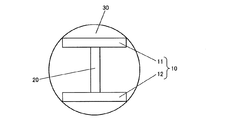
図3は、本体部30の裏面図である。本体部30の裏面部には、略H型に形成された超音波振動子アレイが固定されている。裏面部は、被検者の表皮に接触し、基部40と一体的に表皮に対して変位可能に構成されている。つまり、基部40を左右方向にスライドさせることで、裏面部に形成された超音波振動子アレイの位置も左右方向に変化する。また、本体部30が回転操作された場合も同様に、超音波振動子アレイは回転する。
FIG. 3 is a rear view of the
本実施形態において、超音波振動子アレイは、血管位置判定用アレイ10と、血管性状測定用アレイ20との2種類のアレイを有する。血管位置判定用アレイ10は、超音波測定装置1を装着した被検者の血管位置を判定するために用いられるアレイであり、超音波振動子を第1方向に沿って配列した第1アレイ11と、超音波振動子を第1方向と平行な第2方向に沿って配列した第2アレイ12との2本のアレイを有する。
In the present embodiment, the ultrasonic transducer array has two types of arrays, a blood vessel
血管位置判定用アレイ10は、本体部30を回転させていない状態(向き合わせ用マーカー32が角度目盛りの0度を指している状態。以下、「初期状態」と称する。)において、帯状部80の取り付け方向(測定対象部位への巻き付け方向。バンドであればその長手方向。)と平行な方向に形成されている。血管位置判定用アレイ10は、複数の超音波振動子を直線状に配列して構成されている。
The blood vessel
血管性状測定用アレイ20は、被検者の血管性状を測定するために用いられるアレイ(第3アレイ)である。血管性状測定用アレイ20は、複数の超音波振動子の組でなる超音波振動子組を第1方向に交差する第3方向に沿って配列して構成されている。具体的には、第1アレイ11及び第2アレイ12の中央部に両アレイを連接するように縦方向に第3アレイが形成されており、全体として横向きの略H型が形成されている。血管性状測定用アレイ20は、各超音波振動子組を第1方向に徐々にずらして配列して特徴的な構成を有する。この血管性状測定用アレイ20の構成については詳細に後述する。
The vascular
2.測定位置合わせの原理
本実施形態では、超音波測定装置1による血管性状測定の事前準備として、被検者が自らの手で超音波測定装置1の測定位置合わせを行う。本実施形態において、測定位置合わせとは、血管性状測定用アレイ20が測定対象血管の血管性状測定を行うのに適した向き及び位置となるように、超音波測定装置1を位置決めすることを言う。測定位置合わせには、血管性状測定用アレイ20の向きを測定対象血管の向きに合わせる「向き合わせ」と、血管性状測定用アレイ20の位置を測定対象血管の位置に合わせる「位置合わせ」とがある。
2. Principle of Measurement Positioning In this embodiment, as a preliminary preparation for blood vessel property measurement by the
測定位置合わせでは、超音波測定装置1は、第1アレイ11から表皮に向けて発信させた超音波信号の反射波を測定する。また、第2アレイ12から表皮に向けて発信させた超音波信号の反射波を測定する。そして、これらの測定結果に基づいて、測定対象血管に対する血管性状測定用アレイ20のズレ量及びズレ角を判定する。このズレ量及びズレ角の判定の際には、測定対象血管に対する血管性状測定用アレイ20のズレ方向(左右方向、周方向)を併せて判定する。
In the measurement position alignment, the
ここで、被検者の手首を走る動脈の1つである橈骨動脈を測定対象血管とし、その血管径を血管性状として測定する場合を例に挙げて、測定位置合わせの手順を詳細に説明する。橈骨動脈は、上腕動脈から橈骨に沿って位置し、手掌で尺骨動脈に接続する動脈である。橈骨動脈は、被検者が脈拍数を調べる場合に最も容易に認識することのできる動脈であり、被検者が自らの指で手首に触れることで、その概略位置を特定することができる。 Here, the measurement alignment procedure will be described in detail by taking as an example a case where the radial artery, which is one of the arteries running on the subject's wrist, is the measurement target blood vessel and the blood vessel diameter is measured as a blood vessel property. . The radial artery is an artery located along the radius from the brachial artery and connected to the ulnar artery with the palm. The radial artery is an artery that can be most easily recognized when the subject examines the pulse rate, and the subject can touch the wrist with his / her finger to identify the approximate position.
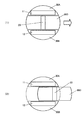
図4は、測定位置合わせの原理の説明図であり、本体部30及び基部40の裏面側を被検者の橈骨動脈とともに示した図である。右上から左下方向に沿ってハッチングを施した太線が橈骨動脈である。最初に被検者は、およそ橈骨動脈の上に本体部30が位置するように超音波測定装置1を装着する。すると、図4(1)に示すように、橈骨動脈の上に血管位置判定用アレイ10(第1アレイ11及び第2アレイ12)が位置することになる。
FIG. 4 is an explanatory diagram of the principle of measurement positioning, and shows the back side of the
この状態において、血管位置判定用アレイ10(第1アレイ11及び第2アレイ12)の超音波振動子から数[MHz]〜数十[MHz]程度の超音波信号を橈骨動脈周辺部に照射し、その反射波である超音波エコーを測定して、橈骨動脈の位置を判定する。超音波信号が動脈を通過する際には、周辺組織や血管壁と比べて、超音波エコーは相対的に小さくなる。そのため、各超音波振動子において超音波エコーの強度が一定時間小さくなる領域を判定し、その領域を橈骨動脈と判定する。血管位置を判定したならば、第1アレイ11及び第2アレイ12に係る超音波信号の反射波の測定結果に基づいて、橈骨動脈に対する血管性状測定用アレイ20の相対位置関係を判定する。
In this state, the peripheral part of the radial artery is irradiated with an ultrasonic signal of several [MHz] to several tens [MHz] from the ultrasonic transducer of the blood vessel position determination array 10 (
図5は、相対位置関係の判定の説明図であり、超音波振動子アレイと橈骨動脈との位置関係を模式的に示した図である。本体部30を裏面側から見た場合に、血管性状測定用アレイ20を基準として、右方向を正、左方向を負と定義する。また、血管性状測定用アレイ20の中心を基準として時計回り方向の回転角を正、反時計回り方向の回転角を負と定義する。
FIG. 5 is an explanatory diagram of the determination of the relative positional relationship, and is a diagram schematically showing the positional relationship between the ultrasonic transducer array and the radial artery. When the
第1アレイ11の長手方向と血管性状測定用アレイ20の長手方向とが交差する点をAとし、第2アレイ12の長手方向と血管性状測定用アレイ20の長手方向とが交差する点をBとする。線分ABの長さは、アレイの寸法によって規定されており、この長さを“L”とする(AB=L)。
A point where the longitudinal direction of the
また、橈骨動脈の中心軸が第1アレイ11と交差する点をCとし、橈骨動脈の中心軸が第2アレイ12と交差する点をDとする。点Aを基準とする点Cの座標を“x1”とし、点Bを基準とする点Dの座標を“x2”とした場合、橈骨動脈に対する血管性状測定用アレイ20のズレ量“d”及びズレ角“θ”は、それぞれ次式(1)及び(2)に従って算出される。

“θ>0”であれば、血管性状測定用アレイ20に対して橈骨動脈は正回転方向に傾いている。そのため、血管性状測定用アレイ20、すなわち本体部30を正回転方向に回転させることで、橈骨動脈の向きに合わせることができる。また、“d>0”であれば、血管性状測定用アレイ20に対して橈骨動脈は正側に位置する。そのため、血管性状測定用アレイ20、すなわち本体部30を有する基部40を正方向に移動させることで、橈骨動脈の位置に合わせることができる。
If “θ> 0”, the radial artery is inclined in the positive rotation direction with respect to the blood vessel
超音波測定装置1は、上記のように判定したズレ量及びズレ角を、そのズレ方向(左右方向、周方向)と併せて被検者に報知する。例えば、超音波測定装置1は、ズレ量及びズレ角を、そのズレ方向と併せて液晶表示器35に表示する。但し、裏面側と表面側とでは左右方向が逆になる。図4の例では、本体部30を反時計回り方向にズレ角“θ”分回転させることを指示するメッセージと、基部40を左方向にズレ量“d”分スライドさせることを指示するメッセージとを液晶表示器35に表示制御する。
The
被検者は、この液晶表示器35の表示に従って測定位置合わせを行う。具体的には、被検者が本体部30を周方向に回転させると、血管位置判定用アレイ10及び血管性状測定用アレイ20を配設した裏面部が表皮と平行を保ちながら回転する。被検者は、本体部30に設けられた向き合わせ用マーカー32を目印として、基部40に刻まれた角度目盛りに従って本体部30を周方向に回転させることで、血管性状測定用アレイ20の向きを測定対象血管の向きに合わせる。
The subject performs measurement position alignment according to the display on the
また、被検者が基部40を左右方向にスライドさせると、血管位置判定用アレイ10及び血管性状測定用アレイ20が形成された裏面部が表皮に対して平行にスライドする。被検者は、基部40に設けられた位置合わせ用マーカー42を目印として、上枠部50及び下枠部60に刻まれた位置目盛りに従って基部40を左右方向にスライドさせることで位置合わせを行う。左方向への移動が指示された場合は、左位置合わせ用マーカー42Lを目印として左位置合わせ用目盛りに沿って基部40を左方向にスライドさせる。また、右方向への移動が指示された場合は、右位置合わせ用マーカー42Rを目印として右位置合わせ用目盛りに沿って基部40を右方向にスライドさせる。
When the subject slides the base 40 in the left-right direction, the back surface portion on which the blood vessel
図4の例では、被検者が液晶表示器35の表示に従って本体部30を正回転方向にズレ角“θ”だけ回転させると、図4(2)に示すように、血管性状測定用アレイ20と橈骨動脈とが平行となる。また、その状態で被検者が基部40を正方向にズレ量“d”だけスライドさせると、図4(3)に示すように、血管性状測定用アレイ20の位置と橈骨動脈の位置とが一致する。これにより、測定位置合わせは完了となる。
In the example of FIG. 4, when the subject rotates the
3.血管性状測定用アレイの構成
本実施形態における血管性状測定用アレイ20(第3アレイ)は、複数の超音波振動子の組でなる超音波振動子組を第1アレイ11の長手方向(第1方向)に交差する第3方向に沿って配列するとともに、各超音波振動子組を第1方向に徐々にずらして配列して構成される。このような構成を採用したことには理由がある。
3. Configuration of Vascular Property Measurement Array In the present embodiment, the vascular property measurement array 20 (third array) is an ultrasonic transducer group composed of a plurality of ultrasonic transducers in the longitudinal direction of the first array 11 (the first array). Are arranged along a third direction that intersects (direction), and the ultrasonic transducer groups are arranged while being gradually shifted in the first direction. There is a reason for adopting such a configuration.
被検者が装置の指示に従って上記の測定位置合わせを適切に行うことができるかどうかは、血管性状測定用アレイ20を橈骨動脈の直上に容易に移動することができるかどうかにかかっている。一般に、血管径の測定には10[μm]程度の精度が要求される。そこで、本実施形態の超音波測定装置1は、10[μm]の算出精度を保証するための構造を有している。それが、血管性状測定用アレイ20(第3アレイ)である。
Whether or not the subject can appropriately perform the above-described measurement alignment according to the instruction of the apparatus depends on whether or not the blood vessel
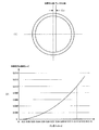
図6(1)は、人間の血管の断面図であり、血管性状測定用アレイ20が血管の中心軸に対して血管横断方向にズレ量“Δx”だけずれた状態を示している。この場合に、ズレ量“Δx”に対して、算出される血管径が実際の血管径に対してどのくらいの誤差になるかを調べた結果を図6(2)に示す。
FIG. 6A is a cross-sectional view of a human blood vessel, and shows a state in which the blood vessel
図6(2)において、横軸はズレ量“Δx”であり、縦軸は血管径算出誤差である。単位は何れもミリメートル[mm]である。このグラフを見ると、ズレ量“Δx”が大きくなるにつれて、血管径算出誤差は指数関数的に増大することがわかる。このグラフによれば、ズレ量“Δx”を0.12[mm]程度とすれば、血管径算出誤差を10[μm]=0.010[mm]に抑えることができることがわかる。 In FIG. 6 (2), the horizontal axis is the deviation amount “Δx”, and the vertical axis is the blood vessel diameter calculation error. All units are millimeters [mm]. From this graph, it can be seen that as the amount of deviation “Δx” increases, the blood vessel diameter calculation error increases exponentially. According to this graph, it is understood that when the deviation amount “Δx” is about 0.12 [mm], the blood vessel diameter calculation error can be suppressed to 10 [μm] = 0.010 [mm].
図7(1)は、人間の血管の上面図であり、血管性状測定用アレイ20が血管中心軸に対してズレ角“φ”だけ角度がずれた状態を図示している。この場合に、血管径算出精度10[μm]を実現するために許容されるズレ角“φ”の大きさを、ズレ量“Δx”を変化させながら計測した結果を図7(2)に示す。ここでは、血管性状測定用アレイ20を構成する超音波振動子組の長手方向の長さを0.6[mm]とした場合の結果を一例として示す。
FIG. 7A is a top view of a human blood vessel, and illustrates a state in which the blood vessel
図7(2)において、横軸はズレ角“φ”であり、単位は度[°]である。また、縦軸はズレ量“Δx”であり、単位はミリメートル[mm]である。このグラフを見ると、上記で説明したズレ量0.12[mm]に対して許容されるズレ角“φ”は23度程度である。被検者が23度程度の回転精度で本体部30を回転させることは容易と考えられるが、0.12[mm]の移動精度で基部40をスライドさせることは困難と考えられる。かかる知見に基づいて、本実施形態では、血管性状測定用アレイ20を以下のように構成した。
In FIG. 7 (2), the horizontal axis is the shift angle “φ”, and the unit is degrees [°]. The vertical axis represents the amount of deviation “Δx”, and the unit is millimeters [mm]. Looking at this graph, the allowable shift angle “φ” with respect to the shift amount of 0.12 [mm] described above is about 23 degrees. It is considered easy for the subject to rotate the
図8は、本実施形態における血管性状測定用アレイ20の構成図である。例えば、5個の超音波振動子を一列に配列した超音波振動子組を1セットとする。そして、超音波振動子組30セットを、血管性状測定用アレイ20の幅方向に所定のずらし幅ずつ斜めにずらしながら配置する。この図では、アレイの左上部から右下部に向かって位置をずらしながら超音波振動子組を斜めに配置した図を示している。
FIG. 8 is a configuration diagram of the blood vessel
隣接する超音波振動子組の第1方向のずらし幅は、図6で説明したズレ量“Δx”と血管径算出精度との関係に基づき0.12[mm]とする。これは、隣接する超音波振動子組の第1方向のずらし幅が、ずらし量と血管径の算出精度との関係に基づいて定められていることを意味する。30セット分であるため、血管性状測定用アレイ20全体としては3[mm]程度の幅となる。
The shift width in the first direction between adjacent ultrasonic transducer groups is set to 0.12 [mm] based on the relationship between the shift amount “Δx” described in FIG. 6 and the blood vessel diameter calculation accuracy. This means that the shift width in the first direction of adjacent ultrasonic transducer groups is determined based on the relationship between the shift amount and the calculation accuracy of the blood vessel diameter. Since there are 30 sets, the entire blood vessel
また、超音波振動子組の長手方向の長さ、及び、当該超音波振動子組を構成する超音波振動子の数を、図7で説明したズレ角“φ”と血管径算出精度との関係に基づき、それぞれ0.6[mm]及び5個とする。これは、超音波振動子組の長手方向の長さ、及び、当該超音波振動子組を構成する超音波振動子の数が、測定対象血管に対する当該長手方向の角度と血管径の算出精度との関係に基づいて定められていることを意味する。 Further, the length of the ultrasonic transducer set in the longitudinal direction and the number of ultrasonic transducers constituting the ultrasonic transducer set are determined by the difference between the deviation angle “φ” and the blood vessel diameter calculation accuracy described in FIG. Based on the relationship, 0.6 [mm] and 5 respectively. This is because the length of the ultrasonic transducer set in the longitudinal direction and the number of ultrasonic transducers constituting the ultrasonic transducer set are calculated with respect to the calculation accuracy of the angle in the longitudinal direction with respect to the measurement target blood vessel and the blood vessel diameter. It is defined based on the relationship.
かかる構成によれば、被検者は、幅方向3[mm]の移動精度で基部40を左右方向にスライドさせることで、少なくとも1組の超音波振動子組を血管の略直上に位置させることが可能となり、10[μm]の血管径算出精度を実現できる。なお、上記のような超音波振動子組の配置構成は、薄膜ピエゾ素子をウェハー上に実装することで容易に作製することができる。
According to such a configuration, the subject slides the
4.機能構成
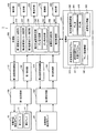
図9は、超音波測定装置1の機能構成の一例を示すブロック図である。超音波測定装置1は、血管位置判定用アレイ10と、血管性状測定用アレイ20と、第1送受信制御部110と、第1送受信部120と、第1検波部130と、第2送受信制御部210と、第2送受信部220と、第2検波部230と、処理部300と、操作部400と、表示部500と、音出力部600と、通信部700と、時計部800と、記憶部900とを備えて構成される。
4). Functional Configuration FIG. 9 is a block diagram illustrating an example of a functional configuration of the
第1送受信制御部110は、第1送受信部120のモードを、血管位置判定用アレイ10へのパルス信号を送信する送信モードと、血管位置判定用アレイ10からの超音波エコーの信号を受信する受信モードとの間で周期的に切り替える制御を行う回路部である。第1送受信制御部110は、処理部300の指示タイミングに従ってトリガー信号を生成し、第1送受信部120に出力する。
The first transmission /
第1送受信部120は、第1送受信制御部110から出力されるトリガー信号に従って、上記の送信モードと受信モードとを時分割方式で切り替える送受信回路である。第1送受信部120は、送信用の構成として、所定周波数のパルス信号を生成する超音波発振回路や、生成されたパルス信号を遅延させる送信遅延回路等を有して構成される。また、受信用の構成として、受信信号を遅延させる受信遅延回路や、受信信号から所定の周波数成分を抽出するフィルター等を有して構成される。
The first transmission /
第1送受信部120は、第1送受信制御部110からトリガー信号を受信している間は、そのトリガー信号に同期したタイミングでパルス信号を発生させ、所定の遅延時間設定値に応じてパルス信号を遅延させて血管位置判定用アレイ10に出力する。これにより、アレイ状に配列した超音波振動子に対して送信波を随時遅延させ、超音波ビームの角度を変化させる位相シフトを実現する。一方、第1送受信制御部110からトリガー信号を受信していない間は、血管位置判定用アレイ10から出力される超音波エコーの受信信号を受信し、所定の遅延時間設定値に応じて受信信号を遅延させて所定の周波数成分を減衰させた後、第1検波部130に出力する。
While the first transmission /
第1検波部130は、第1送受信部120から出力される超音波エコーの受信信号を検波する。第1検波部130は、超音波エコーの受信信号に対して対数圧縮や振幅包絡検波を行う対数検波回路等を有して構成される。
The
第2送受信制御部210、第2送受信部220及び第2検波部230は、血管性状測定用アレイ20を対象とする超音波信号の送受信に係る回路部であり、その構成は第1送受信制御部110、第1送受信部120及び第1検波部130と略同一である。
The 2nd transmission /
処理部300は、記憶部900に記憶されているシステムプログラム等の各種プログラムに従って超音波測定装置1の各部を統括的に制御する制御装置及び演算装置である。処理部300は、CPU(Central Processing Unit)やDSP(Digital Signal Processor)等の各種マイクロプロセッサーや、ASIC(Application Specific Integrated Circuit)、ICメモリーなどの電気電子素子を有して構成される。
The
処理部300は、主要な機能部として、第1超音波エコー測定部310と、第2超音波エコー測定部320と、第3超音波エコー測定部330と、相対位置関係判定部340と、血管性状測定部350と、報知制御部360とを有する。
The
第1及び第2超音波エコー測定部310,320は、第1送受信部120で受信され、第1検波部130によって検波された信号に基づいて、血管位置を判定するための各種パラメーター値を算出する。具体的には、各々の超音波振動子に超音波信号を送出させてから、その反射波が到達するまでの時間(反射波到達時間)や周波数変移量といったパラメーター値を算出する。また、第1及び第2アレイ11,12の各超音波振動子それぞれの個別測定値を算出する。本実施形態において、第1及び第2超音波エコー測定部310,320は、第1及び第2測定部にそれぞれ相当する。
The first and second ultrasonic
第3超音波エコー測定部330は、第2送受信部220で受信され、第2検波部230によって検波された信号に基づいて、血管性状を測定するための各種パラメーター値を算出する。つまり、血管性状測定用アレイ20を構成する超音波振動子組毎の各超音波振動子それぞれについて、反射波到達時間や周波数変移量といったパラメーター値を算出するとともに、各超音波振動子組を構成する超音波振動子毎の個別測定値を算出する。本実施形態において、第3超音波エコー測定部330は、第3測定部に相当する。
The third ultrasonic
相対位置関係判定部340は、第1及び第2超音波エコー測定部310,320の測定結果に基づいて、被検者の測定対象血管に対する血管性状測定用アレイ20の相対位置関係を判定する。相対位置関係判定部340は、ズレ量判定部341と、ズレ角判定部342とを有する。
The relative positional
血管性状測定部350は、第3超音波エコー測定部330の測定結果に基づいて、測定対象血管の血管性状を測定する。本実施形態において、血管性状測定部350は、第3超音波エコー測定部330によって測定された各種パラメーター値を用いて、被検者の測定対象血管の血管径を算出する血管径算出部として機能する。
The vascular
報知制御部360は、被検者に対する各種報知を制御する。具体的には、ズレ量判定部341及びズレ角判定部342によってそれぞれ算出されたズレ量及びズレ角を、そのズレ方向(左右方向、周方向)と併せて表示部500に表示制御する。また、血管性状測定部350によって測定された血管径を表示部500に表示制御する。
The
操作部400は、ボタンスイッチ等を有して構成される入力装置であり、押下されたボタンの信号を処理部300に出力する。この操作部400の操作により、測定位置合わせの開始指示や、血管性状の測定開始指示等の各種指示入力がなされる。操作部400は、ボタンスイッチ34に相当する。
The
表示部500は、LCD(Liquid Crystal Display)等を有して構成され、処理部300から入力される表示信号に基づく各種表示を行う表示装置である。表示部500には、相対位置関係判定部340によって判定された相対位置関係に関する情報(例えばズレ量及びズレ角)や、血管性状測定部350によって測定された血管性状に関する情報(例えば血管径)が表示される。表示部500は、液晶表示器35に相当する。
The
音出力部600は、スピーカー等を有して構成され、処理部300から入力される音出力信号に基づく各種音出力を行う音出力装置である。音出力部600は、スピーカー36に相当する。
The
通信部700は、処理部300の制御に従って、装置内部で利用される情報をパソコン(PC(Personal Computer))等の外部の情報処理装置との間で送受するための通信装置である。この通信部700の通信方式としては、所定の通信規格に準拠したケーブルを介して有線接続する形式や、クレイドルと呼ばれる充電器と兼用の中間装置を介して接続する形式、近距離無線通信を利用して無線接続する形式等、種々の方式を適用可能である。
The
時計部800は、水晶振動子及び発振回路でなる水晶発振器等を有して構成され、時刻を計時する計時装置である。時計部800の計時時刻は、処理部300に随時出力される。
The
記憶部900は、ROM(Read Only Memory)やフラッシュROM、RAM(Random Access Memory)等の記憶装置を有して構成される。記憶部900は、超音波測定装置1のシステムプログラムや、測定位置合わせ支援機能、血管性状測定機能といった各種機能を実現するための各種プログラム、データ等を記憶している。また、各種処理の処理中データ、処理結果などを一時的に記憶するワークエリアを有する。
The
記憶部900には、プログラムとして、例えば、処理部300によって読み出され、超音波測定処理(図10参照)として実行される超音波測定プログラム910が記憶されている。超音波測定プログラム910は、測定位置合わせ支援処理(図11参照)として実行される測定位置合わせ支援プログラム911をサブルーチンとして含む。また、データとして、例えば、アレイ設定情報930と、相対位置関係情報940と、血管性状情報950とが記憶される。
In the
アレイ設定情報930は、血管位置判定用アレイ10及び血管性状測定用アレイ20における超音波振動子の配置構成や、アレイの寸法、アレイの配置構成といったアレイの設定に関する情報である。
The
相対位置関係情報940は、相対位置関係判定部340によって判定された被検者の測定対象血管に対する血管性状測定用アレイ20の相対位置関係に関する情報であり、ズレ量941及びズレ角942がこれに含まれる。
The relative
血管性状情報950は、血管性状測定部350によって測定された測定対象血管の血管性状の情報であり、例えば測定対象血管の血管径がこれに含まれる。
The blood
5.処理の流れ
図10は、処理部300が記憶部900に記憶された超音波測定プログラム910に従って実行する超音波測定処理の流れを示すフローチャートである。
最初に、処理部300は、記憶部900に記憶されている測定位置合わせ支援プログラム911に従って測定位置合わせ支援処理を行う(ステップA1)。
5. Processing Flow FIG. 10 is a flowchart showing a flow of ultrasonic measurement processing executed by the
First, the
図11は、測定位置合わせ支援処理の流れを示すフローチャートである。
先ず、処理部300は、第1送受信制御部110に対して超音波信号の送受信制御を指示する(ステップB1)。これを受けて、第1送受信制御部110は、第1送受信部120のモードを、血管位置判定用アレイ10へのパルス信号を送信する送信モードと、血管位置判定用アレイ10からの受信信号を受信する受信モードとの間で周期的に切り替える制御を行う。
FIG. 11 is a flowchart showing the flow of the measurement alignment support process.
First, the
次いで、第1及び第2超音波エコー測定部310,320は、第1検波部130によって検波された超音波エコーの受信信号に基づいて、第1アレイ11及び第2アレイ12からの超音波エコーの測定を開始する(ステップB3)。そして、相対位置関係判定部340は、第1及び第2超音波エコー測定部310,320の測定結果に基づいて被検者の血管位置を判定する(ステップB5)。
Next, the first and second ultrasonic
次いで、ズレ量判定部341は、ステップB5で判定された血管位置と、記憶部900のアレイ設定情報930とを用いて、式(1)に従ってズレ量941を判定し、相対位置関係情報940として記憶部900に記憶させる(ステップB7)。また、ズレ角判定部342は、ステップB5で判定された血管位置と、記憶部900のアレイ設定情報930とを用いて、式(2)に従ってズレ角942を判定し、相対位置関係情報940として記憶部900に記憶させる(ステップB9)。
Next, the deviation
その後、報知制御部360は、相対位置関係情報940(ズレ量941及びズレ角942)を表示部500に表示制御する(ステップB11)。次いで、処理部300は、測定位置合わせに成功したか否かを判定する(ステップB13)。成功していないと判定した場合は(ステップB13;No)、報知制御部360が、測定位置合わせが未完了であることを被検者に報知制御する(ステップB15)。そして、処理部300は、ステップB5に戻る。
After that, the
一方、ステップB13において測定位置合わせに成功したと判定したならば(ステップB13;Yes)、報知制御部360は、測定位置合わせが完了したことを被検者に報知制御する(ステップB17)。そして、処理部300は、測定位置合わせ支援処理を終了する。
On the other hand, if it is determined in step B13 that the measurement position alignment is successful (step B13; Yes), the
図10の超音波測定処理に戻り、測定位置合わせ支援処理を行ったならば、報知制御部360は、血管性状の測定開始を被検者に報知制御する(ステップA3)。その後、処理部300は、第2送受信制御部210に対して超音波信号の送受信制御を指示する(ステップA5)。これを受けて、第2送受信制御部210は、第2送受信部220のモードを、血管性状測定用アレイ20へのパルス信号を送信する送信モードと、血管性状測定用アレイ20からの受信信号を受信する受信モードとの間で周期的に切り替える制御を行う。
Returning to the ultrasonic measurement process of FIG. 10, if the measurement position alignment support process is performed, the
その後、血管性状測定部350が、血管性状測定処理を行う(ステップA7)。具体的には、血管性状測定用アレイ20を構成する30セットの超音波振動子組のうち、第3超音波エコー測定部330の測定結果が最大を示す超音波振動子組を判定する。つまり、測定位置合わせによって、測定対象血管の中心軸の略直上に位置することとなった超音波振動子組を判定する。そして、当該超音波振動子組について算出された各種パラメーター値を用いて、測定対象血管の血管径を算出する。この際、判定した超音波振動子組を構成する超音波振動子毎の個別測定値を平均処理(例えば加算平均)し、その平均処理結果を用いて血管径を算出することで、血管径を高精度に求めることができる。そして、算出した血管径を血管性状情報950として記憶部900に記憶させる。
Thereafter, the blood vessel
次いで、報知制御部360は、記憶部900に記憶された血管性状情報を表示部500に表示させる制御を行う(ステップA9)。そして、処理部300は、血管性状の測定を終了するか否かを判定し(ステップA11)、まだ終了しないと判定した場合は(ステップA11;No)、ステップA7に戻る。また、測定を終了すると判定した場合は(ステップA11;Yes)、超音波測定処理を終了する。
Next, the
6.作用効果
超音波測定装置1において、本体部30の裏面部には、血管位置判定用アレイ10と血管性状測定用アレイ20との2本のアレイで構成される超音波振動子アレイが構成されている。血管位置判定用アレイ10は、超音波振動子を第1方向に沿って配列した第1アレイ11と、超音波振動子を第1方向と平行な第2方向に沿って配列した第2アレイ12との2本の平行なアレイを有する。血管性状測定用アレイ20は、複数の超音波振動子の組でなる超音波振動子組を第1方向に交差する第3方向に沿って配列し、各超音波振動子組を第1方向に徐々にずらして配列して構成される。
6). In the
血管位置判定用アレイ10を構成する超音波振動子から被検者の表皮に向けて超音波信号が送出される。超音波信号の送出波は測定対象血管において反射し、その反射波が第1及び第2超音波エコー測定部310,320によってそれぞれ測定される。そして、第1及び第2超音波エコー測定部310,320の測定結果に基づいて、被検者の測定対象血管に対する血管性状測定用アレイ20の相対位置関係が相対位置関係判定部340によって判定される。相対位置関係判定部340の判定結果は、表示部500に表示制御されることで被検者に報知される。
An ultrasonic signal is transmitted from the ultrasonic transducers constituting the blood vessel
具体的には、相対位置関係判定部340において、ズレ量判定部341は、第1及び第2超音波エコー測定部310,320の測定結果に基づいて、測定対象血管に対する血管性状測定用アレイ20のズレ量を判定する。また、ズレ角判定部342は、第1及び第2超音波エコー測定部310,320の測定結果に基づいて、測定対象血管に対する血管性状測定用アレイ20のズレ角を判定する。そして、報知制御部360は、これらの判定結果を表示部500に表示制御する。これにより、被検者は、測定対象血管に対する血管性状測定用アレイ20の相対位置関係を知ることができる。そして、被検者は、本体部30を周方向に回転させ、基部40を左右方向にスライドさせることで、血管性状測定用アレイ20が測定対象血管の略直上に位置するように測定位置合わせをすることができる。
Specifically, in the relative positional
測定位置合わせがなされたならば、血管性状測定用アレイ20を構成する超音波振動子組の各超音波振動子から被検者の表皮に向けて超音波信号が送出される。超音波信号の送出波は測定対象血管において反射し、その反射波が第3超音波エコー測定部330によって測定される。そして、第3超音波エコー測定部330の測定結果に基づいて、測定対象血管の血管性状が血管性状測定部350によって測定される。血管性状測定部350の測定結果は、表示部500に表示制御されることで被検者に報知される。
If the measurement position alignment is performed, an ultrasonic signal is transmitted from each ultrasonic transducer of the ultrasonic transducer set constituting the vascular
7.変形例
本発明を適用可能な実施例は、上記の実施例に限定されることなく、本発明の趣旨を逸脱しない範囲で適宜変更可能であることは勿論である。以下、変形例について説明する。
7). Modifications Embodiments to which the present invention can be applied are not limited to the above-described embodiments, and can be changed as appropriate without departing from the spirit of the present invention. Hereinafter, modified examples will be described.
7−1.測定対象血管
上記の実施形態では、被検者の手首の血管(橈骨動脈)を測定対象血管として血管性状の測定を行う場合を例に挙げて説明したが、これは一例に過ぎない。例えば、被検者の首の血管を測定対象血管として、本実施形態の超音波測定装置を被検者の首に装着することも可能である。
7-1. Measurement target blood vessel In the above-described embodiment, the case where blood vessel properties are measured using the blood vessel of the subject's wrist (radial artery) as the measurement target blood vessel has been described as an example, but this is only an example. For example, it is possible to attach the ultrasonic measurement device of the present embodiment to the subject's neck using the subject's neck blood vessel as the blood vessel to be measured.
7−2.アレイの構成
上記の実施形態では、血管位置判定用アレイ10と血管性状測定用アレイ20とが略H型に配置構成されるものとして説明したが、アレイの配置構成はこれに限られない。例えば、血管位置判定用アレイ10と血管性状測定用アレイ20とが略コの字型に配置構成されることとしてもよい。つまり、2本の血管位置判定用アレイ10(第1アレイ11と第2アレイ12)が平行であり、これに交差する方向に第3アレイ(血管性状測定用アレイ20)が配置構成されていればよい。
7-2. Configuration of Array In the above embodiment, the blood vessel
また、血管性状測定用アレイ20における超音波振動子組の配置構成も、図8で説明した配置構成に限られるわけではない。例えば、図12に示すように、左上から右下に向かう方向と、右上から左下に向かう方向とのそれぞれについて、幅方向に所定のずらし幅ずつ位置をずらしながら超音波振動子組を配列してもよい。つまり、各超音波振動子組が第1アレイの第1方向に交差する第3方向に沿って配列されるとともに、各超音波振動子組が第1アレイの第1方向に徐々にずらして配列される構成であれば、任意の配列を採用可能である。
Further, the arrangement configuration of the ultrasonic transducer group in the vascular
また、上記の実施形態では、血管径算出精度10[μm]を実現するために、血管性状測定用アレイ20の隣接する超音波振動子組の幅方向のずらし幅を0.12[mm]としたが、これは一例に過ぎない。つまり、どの程度の血管径算出精度を実現するかに応じてずらし幅は変更することが可能であり、ずらし量と血管径算出精度との関係に応じて適宜の値を設定可能である。
Further, in the above embodiment, in order to realize the blood vessel diameter calculation accuracy of 10 [μm], the shift width in the width direction of the adjacent ultrasonic transducer group of the blood vessel
同様に、血管性状測定用アレイ20を構成する超音波振動子組の長手方向の長さ、及び、当該超音波振動子組を構成する超音波振動子の数についても、上記の実施形態の0.6[mm]や5個といった値に限定されるわけではない。測定対象血管に対する当該長手方向の角度と血管径算出精度との関係に基づいて、適宜の値を設定可能である。
Similarly, the length in the longitudinal direction of the ultrasonic transducer set constituting the blood vessel
7−3.報知方法
上記の実施形態では、被検者が測定位置合わせを行うための情報を液晶表示器35(表示部500)に表示させることで被検者に報知するものとして説明した。しかし、測定位置合わせ用の情報の報知方法はこれに限られない。
7-3. In the above-described embodiment, the description has been made on the assumption that the subject is informed by displaying information for the measurement position alignment on the liquid crystal display 35 (display unit 500). However, the notification method of the information for measuring position alignment is not limited to this.
図13は、変形例における超音波測定装置2の正面図である。なお、超音波測定装置1と同一の構成要素については同一の符号を付して説明を省略する。超音波測定装置2では、基部40の前面に、本体部30の周縁に沿って向き合わせ用の指示器(以下、「向き合わせ用指示器」と称す。)が配設されている。向き合わせ用指示器はLED等によって構成される。報知制御部360は、ズレ角判定部342によって判定されたズレ角及び回転方向に基づいて、対応する角度部分の向き合わせ用指示器を点灯或いは点滅させるなどして被検者に報知する。例えば、図13では、左回転方向の回転角24度の部分の指示器I1が点灯している状態を示しており、被検者は、向き合わせ用マーカー32が指示器I1の部分を指し示すように本体部30を左方向に回転させる。
FIG. 13 is a front view of the
また、上枠部50及び下枠部60の前面には、位置合わせ用の指示器(以下、「位置合わせ用指示器」と称す。)が配設されている。位置合わせ用指示器もLED等によって構成される。報知制御部360は、ズレ量判定部341によって判定されたズレ量及び移動方向に基づいて、対応する移動部分の位置合わせ用指示器を点灯或いは点滅させるなどして被検者に報知する。例えば、図13では、上枠部50の左方向5ミリ部分の指示器I2が点灯している状態を示しており、被検者は、左位置合わせ用マーカー42Lが指示器I2の部分を指し示すように基部40を左方向にスライドさせる。
In addition, an alignment indicator (hereinafter referred to as an “alignment indicator”) is disposed on the front surface of the
また、上記の実施形態では、相対位置関係情報(ズレ量及びズレ角)を液晶表示器35(表示部500)に表示させることで被検者に報知するものとして説明したが、スピーカー36(音出力部600)から音出力させることで被検者に報知することとしてもよい。 In the above embodiment, the relative positional relationship information (deviation amount and deviation angle) is displayed on the liquid crystal display 35 (display unit 500) to notify the subject, but the speaker 36 (sound The subject may be notified by outputting a sound from the output unit 600).
7−4.本体部の構成
上記の実施形態では、本体部30を基部40ごと左右方向にスライドさせることで位置合わせを行うものとして説明した。しかし、位置合わせを行うための本体部30の構成は、何もこれに限られるわけではない。
7-4. Configuration of Main Body In the above-described embodiment, it has been described that alignment is performed by sliding the
図14は、変形例における本体部30の構成図であり、本体部30を裏面側から見た図である。図14(1)に示すように、本体部30の裏面側は3つのパーツに分かれており、第1アレイ11が固定された第1パーツ30Aと、第2アレイ12が固定された第2パーツ30Bと、血管性状測定用アレイ20が固定された第3パーツ30Cとを有する。
FIG. 14 is a configuration diagram of the
第1パーツ30A及び第2パーツ30Bは、本体部30に対して固定されている。しかし、第3パーツ30Cは、図14(2)に示すように、左右方向にスライド可能に構成されている。従って、本体部30を回転させることで超音波振動子アレイ全体を回転可能である。また、第3パーツ30Cをスライドさせることで血管性状測定用アレイ20をスライド移動させることが可能である。
The
なお、第3パーツ30Cをスライドさせるための機構としては、種々の機構を適用可能である。例えば、腕時計の竜頭(リューズ)に類する機構を本体部30に設け、竜頭を回転させることで第3パーツ30Cをスライドさせる構成としてもよい。
In addition, as a mechanism for sliding the
1,2 超音波測定装置、 10 血管位置判定用アレイ、 11 第1アレイ、 12 第2アレイ、 20 血管性状測定用アレイ、 30 本体部、 40 基部、 50 上枠部、 52 上枠スライド溝、 60 下枠部、 62 下枠スライド溝、 70 支持部、 80 帯状部、 110 第1送受信制御部、 120 第1送受信部、 130 第1検波部、 210 第2送受信制御部、 220 第2送受信部、 230 第2検波部、 300 処理部、 400 操作部、 500 表示部、 600 音出力部、 700 通信部、 800 時計部、 900 記憶部
DESCRIPTION OF
Claims (6)
前記第1方向と平行な第2方向に配列された超音波振動子の第2アレイと、
前記第1方向に交差する第3方向に配列された超音波振動子の第3アレイと、
前記超音波振動子の第1アレイから血管に対して発信された超音波の反射波を測定する第1測定部と、
前記超音波振動子の第2アレイから前記血管に対して発信された超音波の反射波を測定する第2測定部と、
前記超音波振動子の第3アレイから前記血管に対して発信された超音波の反射波を測定する第3測定部と、
前記第1測定部と第2測定部との測定結果に基づいて、前記血管に対する前記第3アレイの位置を判定する位置判定部と、
前記位置判定部の判定結果と前記第3測定部の測定結果とに基づいて、前記血管の血管径を算出する血管径算出部と、
を備えた超音波測定装置であって、
前記超音波振動子の第3アレイは、前記血管の血管径の算出精度に基づいて配置された超音波測定装置。 A first array of ultrasonic transducers arranged in a first direction;
A second array of ultrasonic transducers arranged in a second direction parallel to the first direction;
A third array of ultrasonic transducers arranged in a third direction intersecting the first direction;
A first measurement unit for measuring a reflected wave of an ultrasonic wave transmitted from a first array of the ultrasonic transducers to a blood vessel;
A second measuring unit for measuring a reflected wave of an ultrasonic wave transmitted from the second array of the ultrasonic transducers to the blood vessel;
A third measurement unit for measuring a reflected wave of an ultrasonic wave transmitted from the third array of the ultrasonic transducers to the blood vessel;
A position determination unit that determines a position of the third array with respect to the blood vessel based on measurement results of the first measurement unit and the second measurement unit;
A blood vessel diameter calculating unit that calculates a blood vessel diameter of the blood vessel based on the determination result of the position determination unit and the measurement result of the third measurement unit;
An ultrasonic measuring device comprising :
The third array of the ultrasonic transducers is an ultrasonic measurement device arranged based on the calculation accuracy of the blood vessel diameter of the blood vessel.
前記第1方向と平行な第2方向に配列された超音波振動子の第2アレイと、
前記第1方向に交差する第3方向に配列された超音波振動子の第3アレイと、
前記超音波振動子の第1アレイから血管に対して発信された超音波の反射波を測定する第1測定部と、
前記超音波振動子の第2アレイから前記血管に対して発信された超音波の反射波を測定する第2測定部と、
前記超音波振動子の第3アレイから前記血管に対して発信された超音波の反射波を測定する第3測定部と、
前記第1測定部と第2測定部との測定結果に基づいて、前記血管に対する前記第3アレイの位置を判定する位置判定部と、
前記位置判定部の判定結果と前記第3測定部の測定結果とに基づいて、前記血管の血管径を算出する血管径算出部と、
を備えた超音波測定装置であって、
前記超音波振動子の第3アレイは、前記超音波振動子の長手方向の長さ、及び、前記超音波振動子の数が、前記血管に対する前記超音波振動子の長手方向の角度と前記血管の血管径の算出精度とに基づいて定められてなる超音波測定装置。 A first array of ultrasonic transducers arranged in a first direction;
A second array of ultrasonic transducers arranged in a second direction parallel to the first direction;
A third array of ultrasonic transducers arranged in a third direction intersecting the first direction;
A first measurement unit for measuring a reflected wave of an ultrasonic wave transmitted from a first array of the ultrasonic transducers to a blood vessel;
A second measuring unit for measuring a reflected wave of an ultrasonic wave transmitted from the second array of the ultrasonic transducers to the blood vessel;
A third measurement unit for measuring a reflected wave of an ultrasonic wave transmitted from the third array of the ultrasonic transducers to the blood vessel;
A position determination unit that determines a position of the third array with respect to the blood vessel based on measurement results of the first measurement unit and the second measurement unit;
A blood vessel diameter calculating unit that calculates a blood vessel diameter of the blood vessel based on the determination result of the position determination unit and the measurement result of the third measurement unit;
An ultrasonic measuring device comprising :
In the third array of the ultrasonic transducers, the length of the ultrasonic transducers in the longitudinal direction, and the number of the ultrasonic transducers are the angle in the longitudinal direction of the ultrasonic transducers with respect to the blood vessels and the blood vessels. An ultrasonic measurement device determined based on the calculation accuracy of the blood vessel diameter.
Priority Applications (1)
| Application Number | Priority Date | Filing Date | Title |
|---|---|---|---|
| JP2011154505A JP5887740B2 (en) | 2011-07-13 | 2011-07-13 | Ultrasonic measuring device |
Applications Claiming Priority (1)
| Application Number | Priority Date | Filing Date | Title |
|---|---|---|---|
| JP2011154505A JP5887740B2 (en) | 2011-07-13 | 2011-07-13 | Ultrasonic measuring device |
Publications (3)
| Publication Number | Publication Date |
|---|---|
| JP2013017721A JP2013017721A (en) | 2013-01-31 |
| JP2013017721A5 JP2013017721A5 (en) | 2014-08-07 |
| JP5887740B2 true JP5887740B2 (en) | 2016-03-16 |
Family
ID=47689762
Family Applications (1)
| Application Number | Title | Priority Date | Filing Date |
|---|---|---|---|
| JP2011154505A Expired - Fee Related JP5887740B2 (en) | 2011-07-13 | 2011-07-13 | Ultrasonic measuring device |
Country Status (1)
| Country | Link |
|---|---|
| JP (1) | JP5887740B2 (en) |
Families Citing this family (4)
| Publication number | Priority date | Publication date | Assignee | Title |
|---|---|---|---|---|
| IL255098B (en) * | 2017-10-17 | 2022-07-01 | Pulsenmore Ltd | Wearable ultrasonic device |
| JP7124949B2 (en) * | 2019-02-27 | 2022-08-24 | 株式会社村田製作所 | Blood vessel position detection device and blood flow measurement device |
| JPWO2022153727A1 (en) * | 2021-01-18 | 2022-07-21 | ||
| KR200497688Y1 (en) * | 2023-10-13 | 2024-01-25 | 주식회사 한소노 | Ultrasound device |
Family Cites Families (6)
| Publication number | Priority date | Publication date | Assignee | Title |
|---|---|---|---|---|
| JP2006122581A (en) * | 2004-11-01 | 2006-05-18 | Shimadzu Corp | Probe for ultrasonic diagnostic apparatus |
| JP4855182B2 (en) * | 2005-08-29 | 2012-01-18 | 株式会社ユネクス | Blood vessel image measuring device |
| JP4892732B2 (en) * | 2007-03-28 | 2012-03-07 | 国立大学法人岐阜大学 | Blood vessel imaging method, blood vessel imaging system, and blood vessel imaging program |
| JP5155007B2 (en) * | 2007-06-04 | 2013-02-27 | パナソニック株式会社 | Ultrasonic diagnostic apparatus and ultrasonic probe used for ultrasonic diagnostic apparatus |
| JP5411272B2 (en) * | 2009-07-16 | 2014-02-12 | 株式会社ユネクス | Ultrasound angiography equipment |
| JP2012223367A (en) * | 2011-04-20 | 2012-11-15 | Fujifilm Corp | Photoacoustic image generation apparatus and method |
-
2011
- 2011-07-13 JP JP2011154505A patent/JP5887740B2/en not_active Expired - Fee Related
Also Published As
| Publication number | Publication date |
|---|---|
| JP2013017721A (en) | 2013-01-31 |
Similar Documents
| Publication | Publication Date | Title |
|---|---|---|
| JP5884256B2 (en) | Blood pressure measuring device and blood pressure measuring method | |
| KR101624846B1 (en) | Ultrasonic blood vessel examination apparatus | |
| JP5499939B2 (en) | Measuring device, biopsy device, flow velocity measuring method, and pressure measuring method | |
| EP1772102A1 (en) | Blood vessel shape measuring instrument, blood flow velocity measuring instrument, and blood flow measuring instrument | |
| JP5887740B2 (en) | Ultrasonic measuring device | |
| JP5742520B2 (en) | Biological information processing apparatus and biological information processing method | |
| JP2016112277A (en) | Blood pressure measurement device, electronic apparatus and blood pressure measurement method | |
| JP6775002B2 (en) | Electronics | |
| JP7119127B2 (en) | Ultrasonic system and method of controlling the ultrasonic system | |
| JPWO2017010193A1 (en) | Probe adapter, ultrasonic imaging apparatus, ultrasonic imaging method, and ultrasonic imaging program | |
| JP2016036644A (en) | Ultrasonic blood pressure measurement apparatus and blood pressure measurement method | |
| JP6158324B2 (en) | Blood vessel abnormality detection device | |
| US20150243190A1 (en) | Blood pressure measurement apparatus | |
| US11241172B2 (en) | Ultrasonic diagnostic apparatus and method of controlling the same | |
| JP2006247214A (en) | Ultrasonic probe, and ultrasonic diagnostic apparatus using the same | |
| JP5686030B2 (en) | Ultrasonic measuring device and ultrasonic measuring method | |
| JP2009039407A (en) | Ultrasonic diagnosis device, and ultrasonic probe for use in ultrasonic diagnosis device | |
| WO2019211961A1 (en) | Electronic device | |
| JP2004242851A (en) | Pulse wave measuring electrode and pulse wave measuring device | |
| JP2016174798A (en) | Blood pressure measurement apparatus and calibration method | |
| JP2012065747A (en) | Device and method for measuring fluid pulsation pressure, and device and method for measuring pulse pressure | |
| JP2015166024A (en) | Ultrasonic sensor and ultrasonic measurement device | |
| JPH05237109A (en) | Method for measuring position of at least one moving contact face using ultrasonic wave and device implementing the method | |
| JP2015093140A (en) | Ultrasonic measurement device | |
| JP5319383B2 (en) | Ultrasonic image processing device |
Legal Events
| Date | Code | Title | Description |
|---|---|---|---|
| A521 | Written amendment |
Free format text: JAPANESE INTERMEDIATE CODE: A523 Effective date: 20140625 |
|
| A621 | Written request for application examination |
Free format text: JAPANESE INTERMEDIATE CODE: A621 Effective date: 20140625 |
|
| RD04 | Notification of resignation of power of attorney |
Free format text: JAPANESE INTERMEDIATE CODE: A7424 Effective date: 20150107 |
|
| A131 | Notification of reasons for refusal |
Free format text: JAPANESE INTERMEDIATE CODE: A131 Effective date: 20150616 |
|
| A521 | Written amendment |
Free format text: JAPANESE INTERMEDIATE CODE: A523 Effective date: 20150806 |
|
| TRDD | Decision of grant or rejection written | ||
| A01 | Written decision to grant a patent or to grant a registration (utility model) |
Free format text: JAPANESE INTERMEDIATE CODE: A01 Effective date: 20160119 |
|
| A61 | First payment of annual fees (during grant procedure) |
Free format text: JAPANESE INTERMEDIATE CODE: A61 Effective date: 20160201 |
|
| R150 | Certificate of patent or registration of utility model |
Ref document number: 5887740 Country of ref document: JP Free format text: JAPANESE INTERMEDIATE CODE: R150 |
|
| S531 | Written request for registration of change of domicile |
Free format text: JAPANESE INTERMEDIATE CODE: R313531 |
|
| R350 | Written notification of registration of transfer |
Free format text: JAPANESE INTERMEDIATE CODE: R350 |
|
| LAPS | Cancellation because of no payment of annual fees |