JP5887258B2 - Absorbent articles - Google Patents
Absorbent articles Download PDFInfo
- Publication number
- JP5887258B2 JP5887258B2 JP2012264209A JP2012264209A JP5887258B2 JP 5887258 B2 JP5887258 B2 JP 5887258B2 JP 2012264209 A JP2012264209 A JP 2012264209A JP 2012264209 A JP2012264209 A JP 2012264209A JP 5887258 B2 JP5887258 B2 JP 5887258B2
- Authority
- JP
- Japan
- Prior art keywords
- elastic member
- leg
- elastic members
- waistline region
- disposed
- Prior art date
- Legal status (The legal status is an assumption and is not a legal conclusion. Google has not performed a legal analysis and makes no representation as to the accuracy of the status listed.)
- Active
Links
- 230000002745 absorbent Effects 0.000 title claims description 33
- 239000002250 absorbent Substances 0.000 title claims description 33
- 210000001364 upper extremity Anatomy 0.000 claims description 31
- 239000006096 absorbing agent Substances 0.000 claims description 23
- 239000004745 nonwoven fabric Substances 0.000 description 12
- 230000008602 contraction Effects 0.000 description 9
- 239000004831 Hot glue Substances 0.000 description 4
- -1 polypropylene Polymers 0.000 description 4
- 230000000638 stimulation Effects 0.000 description 4
- 239000004743 Polypropylene Substances 0.000 description 3
- 230000007794 irritation Effects 0.000 description 3
- 238000000034 method Methods 0.000 description 3
- 229920001155 polypropylene Polymers 0.000 description 3
- 210000001015 abdomen Anatomy 0.000 description 2
- 238000010521 absorption reaction Methods 0.000 description 2
- 239000000853 adhesive Substances 0.000 description 2
- 230000001070 adhesive effect Effects 0.000 description 2
- 210000001124 body fluid Anatomy 0.000 description 2
- 239000010839 body fluid Substances 0.000 description 2
- 239000004698 Polyethylene Substances 0.000 description 1
- 230000004323 axial length Effects 0.000 description 1
- 238000000576 coating method Methods 0.000 description 1
- 239000002131 composite material Substances 0.000 description 1
- 229920001971 elastomer Polymers 0.000 description 1
- 230000004927 fusion Effects 0.000 description 1
- 239000012943 hotmelt Substances 0.000 description 1
- 230000002209 hydrophobic effect Effects 0.000 description 1
- 238000004519 manufacturing process Methods 0.000 description 1
- 239000000463 material Substances 0.000 description 1
- 239000011812 mixed powder Substances 0.000 description 1
- 230000004048 modification Effects 0.000 description 1
- 238000012986 modification Methods 0.000 description 1
- 230000002746 orthostatic effect Effects 0.000 description 1
- 239000002985 plastic film Substances 0.000 description 1
- 229920006255 plastic film Polymers 0.000 description 1
- 229920000573 polyethylene Polymers 0.000 description 1
- 239000005060 rubber Substances 0.000 description 1
- 229920000247 superabsorbent polymer Polymers 0.000 description 1
- 229920003051 synthetic elastomer Polymers 0.000 description 1
- 239000005061 synthetic rubber Substances 0.000 description 1
- 239000002759 woven fabric Substances 0.000 description 1
Images


Classifications
-
- A—HUMAN NECESSITIES
- A61—MEDICAL OR VETERINARY SCIENCE; HYGIENE
- A61F—FILTERS IMPLANTABLE INTO BLOOD VESSELS; PROSTHESES; DEVICES PROVIDING PATENCY TO, OR PREVENTING COLLAPSING OF, TUBULAR STRUCTURES OF THE BODY, e.g. STENTS; ORTHOPAEDIC, NURSING OR CONTRACEPTIVE DEVICES; FOMENTATION; TREATMENT OR PROTECTION OF EYES OR EARS; BANDAGES, DRESSINGS OR ABSORBENT PADS; FIRST-AID KITS
- A61F13/00—Bandages or dressings; Absorbent pads
- A61F13/15—Absorbent pads, e.g. sanitary towels, swabs or tampons for external or internal application to the body; Supporting or fastening means therefor; Tampon applicators
- A61F13/45—Absorbent pads, e.g. sanitary towels, swabs or tampons for external or internal application to the body; Supporting or fastening means therefor; Tampon applicators characterised by the shape
- A61F13/49—Absorbent articles specially adapted to be worn around the waist, e.g. diapers
- A61F13/49007—Form-fitting, self-adjusting disposable diapers
- A61F13/49009—Form-fitting, self-adjusting disposable diapers with elastic means
- A61F13/49011—Form-fitting, self-adjusting disposable diapers with elastic means the elastic means is located at the waist region
-
- A—HUMAN NECESSITIES
- A61—MEDICAL OR VETERINARY SCIENCE; HYGIENE
- A61F—FILTERS IMPLANTABLE INTO BLOOD VESSELS; PROSTHESES; DEVICES PROVIDING PATENCY TO, OR PREVENTING COLLAPSING OF, TUBULAR STRUCTURES OF THE BODY, e.g. STENTS; ORTHOPAEDIC, NURSING OR CONTRACEPTIVE DEVICES; FOMENTATION; TREATMENT OR PROTECTION OF EYES OR EARS; BANDAGES, DRESSINGS OR ABSORBENT PADS; FIRST-AID KITS
- A61F13/00—Bandages or dressings; Absorbent pads
- A61F13/15—Absorbent pads, e.g. sanitary towels, swabs or tampons for external or internal application to the body; Supporting or fastening means therefor; Tampon applicators
- A61F13/45—Absorbent pads, e.g. sanitary towels, swabs or tampons for external or internal application to the body; Supporting or fastening means therefor; Tampon applicators characterised by the shape
- A61F13/49—Absorbent articles specially adapted to be worn around the waist, e.g. diapers
- A61F13/49007—Form-fitting, self-adjusting disposable diapers
- A61F13/49009—Form-fitting, self-adjusting disposable diapers with elastic means
- A61F13/49017—Form-fitting, self-adjusting disposable diapers with elastic means the elastic means being located at the crotch region
-
- A—HUMAN NECESSITIES
- A61—MEDICAL OR VETERINARY SCIENCE; HYGIENE
- A61F—FILTERS IMPLANTABLE INTO BLOOD VESSELS; PROSTHESES; DEVICES PROVIDING PATENCY TO, OR PREVENTING COLLAPSING OF, TUBULAR STRUCTURES OF THE BODY, e.g. STENTS; ORTHOPAEDIC, NURSING OR CONTRACEPTIVE DEVICES; FOMENTATION; TREATMENT OR PROTECTION OF EYES OR EARS; BANDAGES, DRESSINGS OR ABSORBENT PADS; FIRST-AID KITS
- A61F13/00—Bandages or dressings; Absorbent pads
- A61F13/15—Absorbent pads, e.g. sanitary towels, swabs or tampons for external or internal application to the body; Supporting or fastening means therefor; Tampon applicators
- A61F13/45—Absorbent pads, e.g. sanitary towels, swabs or tampons for external or internal application to the body; Supporting or fastening means therefor; Tampon applicators characterised by the shape
- A61F13/49—Absorbent articles specially adapted to be worn around the waist, e.g. diapers
- A61F13/49007—Form-fitting, self-adjusting disposable diapers
- A61F13/49009—Form-fitting, self-adjusting disposable diapers with elastic means
- A61F13/49019—Form-fitting, self-adjusting disposable diapers with elastic means the elastic means being placed longitudinally, transversely or diagonally over the article
Landscapes
- Health & Medical Sciences (AREA)
- Epidemiology (AREA)
- Engineering & Computer Science (AREA)
- Biomedical Technology (AREA)
- Heart & Thoracic Surgery (AREA)
- Vascular Medicine (AREA)
- Life Sciences & Earth Sciences (AREA)
- Animal Behavior & Ethology (AREA)
- General Health & Medical Sciences (AREA)
- Public Health (AREA)
- Veterinary Medicine (AREA)
- Absorbent Articles And Supports Therefor (AREA)
Description
本発明は、パンツタイプの吸収性物品に関する。 The present invention relates to a pants-type absorbent article.
特許文献1に、着用者の腹側に配置される前身頃と着用者の背側に配置される後身頃との対応する側縁部同士が接合されて、着用者の脚回りが挿入される脚回り開口と、着用者の胴回りが挿入される胴回り開口とが形成されたパンツ型の吸収性物品が開示されている。
In
特許文献1の吸収性物品は、前身頃と後身頃とが接合された接合部において、前身頃に配置された脚回り弾性部材の端部位置と、後見頃に配置された脚回り弾性部材の端部位置と、を少なくとも1か所、前後方向にずらして配置されている。前身頃の脚回り弾性部材と後見頃の脚回り弾性部材とがずれている部分は、前身頃の脚回り弾性部材と後見頃の脚回り弾性部材とが重なる部分と比較して、接合部の剛性が低く、違和感を低減できる。
The absorbent article of
しかし、特許文献1の吸収性物品には、以下の問題点があった。
However, the absorbent article of
接合部の前後方向内側端部(股下側の端部)は、着用者の脚回りに配置されている。接合部は、接合部に隣接する前身頃や後身頃よりも剛性が高く、接合部の前後方向内側端部が着用者に当たって、着用者に刺激を与えるおそれがある。 The front-rear direction inner end portion (end portion on the crotch side) of the joint portion is disposed around the wearer's leg. The joint portion has higher rigidity than the front body and the rear body adjacent to the joint portion, and the inner end portion in the front-rear direction of the joint portion may hit the wearer, and may cause irritation to the wearer.
特許文献1の吸収性物品は、前身頃の脚回り弾性部材と後身頃の脚回り弾性部材とがずれている部分では、前身頃側の伸縮力と後身頃側の伸縮力が異なり、接合部が前身頃又は後身頃に寄せられることが考えられる。
The absorbent article of
しかし、前身頃の脚回り弾性部材と後身頃の脚回り弾性部材とがずれている部分において、サイド接合部の一部が前身頃側か後身頃側に寄せられた場合であっても、前後方向内側端部(股下側の端部)が前身頃又は後身頃に十分に寄せられず、接合部の前後方向内側端部が着用者の脚に当たるおそれがある。 However, before the leg elastic members and the leg elastic members and a portion is displaced in the rear body of the body, even if a part of the side joint is provided by, the rear body side or front body side, front and rear The inner end in the direction (the end on the crotch side) is not sufficiently brought close to the front body or the rear body , and the inner end in the front-rear direction of the joint may hit the wearer's leg.
そこで、本発明は、前胴回り域と後胴回り域を接合するサイド接合部による肌への刺激を抑制し、装着感を向上できる吸収性物品を提供することを目的とする。 Then, an object of this invention is to provide the absorbent article which can suppress the irritation | stimulation to the skin by the side junction part which joins a front waistline area and a back waistline area, and can improve a wearing feeling.
本発明に係る吸収性物品は、身体前側と身体後側とに延びる前後方向と、前記前後方向に直交する幅方向と、前記着用者に向かう内方向及び前記内方向と反対側に向かう外方向を有する厚み方向とを有する吸収体を有する吸収性本体と、前記吸収性本体よりも前記外方向に配置される外装体と、を備え、着用者の腹側に配置される前胴回り域と、着用者の背側に配置される後胴回り域と、前記前胴回り域と前記後胴回り域との間に位置し、着用者の股下に配置される股下域とを有し、前記外装体の前記前胴回り域の前記幅方向外側端部と前記外装体の前記後胴回り域の前記幅方向外側端部とが接合された一対のサイド接合部が形成されることにより、前記着用者の脚が挿入される一対の脚回り開口部が設けられるパンツタイプの吸収性物品であって、前記外装体には、前記前胴回り域又は前記後胴回り域の一方の脚回り開口部に沿って配置された複数の第1弾性部材と、前記前胴回り域又は前記後胴回り域の他方の脚回り開口部に沿って配置された複数の第2弾性部材と、が設けられており、前記複数の第1弾性部材及び前記複数の第2弾性部材が伸長した伸長状態において、前記複数の第1弾性部材のうち最も前記脚回り開口部側に位置する端部第1弾性部材と前記幅方向に延びる仮想線とがなす角度は、前記複数の第2弾性部材のうち最も前記脚回り開口部側に位置する端部第2弾性部材と前記仮想線とがなす角度よりも大きく、前記端部第2弾性部材の前記幅方向の伸縮力は、前記端部第1弾性部材の前記幅方向の伸縮力よりも高いことを要旨とする。 Absorbent article according to the present invention, a longitudinal direction extending in the body front and the body rear side, a width direction perpendicular to the longitudinal direction, an outer direction toward the side opposite to the direction and the plane direction within toward the wearer A front waistline region disposed on the abdomen side of the wearer, comprising an absorbent body having an absorbent body having a thickness direction and an exterior body disposed more outward than the absorbent body; A rear waistline region disposed on the back side of the wearer, and a crotch region located between the front waistline region and the back waistline region and disposed on the wearer's inseam, The wearer's leg is inserted by forming a pair of side joints in which the widthwise outer end of the front waistline and the widthwise outer end of the rear waistline of the exterior body are joined. A pants-type absorbent article provided with a pair of leg openings. The outer body includes a plurality of first elastic members disposed along one leg opening of the front waistline or the rear waistline, and the other of the front waistline or the rear waistline. A plurality of second elastic members disposed along the leg opening of the plurality of legs, and in the extended state where the plurality of first elastic members and the plurality of second elastic members are extended, The angle formed by the end first elastic member located closest to the leg opening portion of the first elastic member and the imaginary line extending in the width direction is the most around the leg opening of the plurality of second elastic members. The expansion / contraction force in the width direction of the end second elastic member is larger than the angle formed by the end second elastic member located on the portion side and the imaginary line, and the width direction of the end first elastic member is The gist is that it is higher than the elastic force of
本開示によれば、前胴回り域と後胴回り域を接合するサイド接合部による肌への刺激を抑制し、装着感を向上できる吸収性物品を提供することができる。 ADVANTAGE OF THE INVENTION According to this indication, the irritation | stimulation to the skin by the side junction part which joins a front waist area and a back waist area can be suppressed, and the absorbent article which can improve a mounting feeling can be provided.
次に、実施の形態に係る吸収性物品としての使い捨ておむつ1について、図面を参照しながら説明する。なお、以下の図面の記載において、同一または類似の部分には、同一または類似の符号を付している。ただし、図面は模式的なものであり、各寸法の比率などは現実のものとは異なることに留意すべきである。従って、具体的な寸法などは以下の説明を参酌して判断すべきである。また、図面相互間においても互いの寸法の関係や比率が異なる部分が含まれ得る。
Next, a
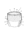
まず、図1及び図2に基づいて吸収性物品としての使い捨ておむつの全体構成について説明する。図1は、本実施の形態において使い捨ておむつを構成する使い捨ておむつ1の概略斜視図である。図2は、本実施の形態に係る使い捨ておむつ1の展開平面図である。使い捨ておむつ1は、パンツ型の使い捨ておむつである。
First, the whole structure of the disposable diaper as an absorbent article is demonstrated based on FIG.1 and FIG.2. FIG. 1 is a schematic perspective view of a
使い捨ておむつ1は、着用者の身体前側と身体後側とに延びる前後方向Lと、前後方向Lに直交する幅方向Wと、着用者に向かう内方向及び内方向と反対側に向かう外方向を有する厚み方向と、を有する。
The
使い捨ておむつ1は、図2に示すように、使い捨ておむつ1の前後方向において、着用者の前胴回りに当てられる前胴回り域S1と、着用者の後胴回りに当てられる後胴回り域S2と、着用者の股下に当てられ、前胴回り域S1と後胴回り域S2との間に位置する股下域S3と、を有する。
As shown in FIG. 2, the
前胴回り域S1の幅方向W外側に位置する前胴回り縁部4が、後胴回り域S2の幅方向Wの外側に位置する後胴回り縁部4’と接合され、かつ前胴回り縁部6が、後胴回り縁部6’と接合されることによって、使い捨ておむつ1がパンツ型に形成される。パンツ型の使い捨ておむつの前胴回り域及び後胴回り域には、互いの縁部が接合されたサイド接合部11が形成されており、股下域S3は、サイド接合部11よりも前後方向内側の領域である。サイド接合部11の構成及び装着時の変形態様については、後述にて詳細に説明する。
The
使い捨ておむつ1には、図1に示すように、パンツ型に形成された状態(一対のサイド接合部が形成された状態)で、着用者の腰回りを囲んで配置される腰回り開口部8と、着用者の脚回りを囲んで配置される一対の脚回り開口部9と、が形成される。
As shown in FIG. 1, the
使い捨ておむつ1は、表面シート10、吸収体40及び吸収体裏面シート(図示せず)等を含む吸収性本体1Aと、前側外装シート70F、後側外装シート70R等を含む外装体1Bと、から構成されており、これらは互いに、接着剤や熱融着などによって接合されている。
The
外装体1Bは、前胴回り域と股下域とに跨って配置される前側外装シート70Fと、後胴回り域と股下域とに跨って配置される後側外装シート70Rと、前胴回り域から後胴回り域に亘って配置される外装センターシート100と、を含み、使い捨ておむつ1の外装部分を構成する。外装体1Bは、吸収体40を含む吸収性本体1Aよりも外方向に位置し、使い捨ておむつの非肌当接側の面に配置される。
The
前側外装シート70Fは、前胴回り域S1と股下域S3とに跨がって配置されており、使い捨ておむつの前側端部において幅方向に沿った折り目を基点に内方向に折り返されている。前側外装シート70Fの折り返されたシート間には、外装センターシート100が配置されている。後側外装シート70Rは、後胴回り域S2と股下域S3とに跨がって配置されており、使い捨ておむつの後側端部において幅方向に沿った折り目を基点に内方向に折り返されている。後側外装シート70Rの折り返されたシート間には、外装センターシート100が配置されている。
The
前側外装シート70F及び後側外装シート70Rは、エアスルー不織布、スパンボンド不織布、SMS不織布、防水フィルムなどによって形成できる。本実施の形態に係る前側外装シート70F及び後側外装シート70Rは、ポリプロピレンからなる目付20g/m2のスパンボンド不織布によって形成されている。
The
外装センターシート100は、前側外装シート70Fと、後側外装シート70Rとを繋ぐ。よって、前側外装シート及び後側外装シートが前後方向に離間する形態において、吸収性本体1Aがむき出しになることを防止することができる。更に、製造過程において、離間した前側外装体と後側外装体とを連結した状態で、脚回り開口部を形成したり、吸収性本体1Aと貼り合わせたりすることができる。
The
外装センターシート100は、エアスルー不織布、スパンボンド不織布、SMS不織布、防水フィルムなどによって形成できる。本実施の形態に係る外装センターシート100は、ポリプロピレンからなる目付15g/ m2のSMS不織布によって形成されている。
The
吸収性本体1Aは、表面シート10、吸収体裏面シート及びレッグサイドギャザーを含み、外装体1Bよりも着用者側に配置される。
The absorbent
表面シート10は、着用者の肌に直接的に接し得る肌当接面を形成するシートである。表面シート10は、吸収体40よりも肌当接面側に配置される。表面シート10は、親水性不織布や織物、開口プラスチックフィルム、開口疎水性不織布などの液透過性のシートによって形成されている。本実施の形態に係る表面シート10は、ポリプロピレンからなる目付20g/m2の親水性スパンボンド不織布によって形成されている。表面シート10は、吸収体40の肌当接側の面よりも幅方向両側に延出し、吸収体の幅方向外側端部を覆って吸収体の非肌当接面側に到達している。
The
表面シート10の非肌当接面側には、セカンドシートが設けられていてもよい。セカンドシートを設けることにより、体液の吸収速度を速くすることができ、かつ吸収後における体液の逆戻りを抑制することができる。
A second sheet may be provided on the non-skin contact surface side of the
吸収体40は、表面シート10と、吸収体裏面シートとの間にホットメルト型接着剤によって接合される。ホットメルト型接着剤は、複合シート及び裏面シートにそれぞれ塗工され、例えば、スパイラル塗工方法により、それぞれ目付5g/m2,8g/m2で塗られる。
The
吸収体40は、粉砕パルプや高吸収性ポリマーなどの混合粉体で形成される。平面視にて、吸収体40の形状は、略砂時計形状である。
The
吸収体裏面シートは、吸収体40の非肌当接面側に設けられている。吸収体裏面シートは、液不透過性フィルムなど(例えば、ポリエチレン)のシートによって形成されている。吸収体裏面シートは、吸収体よりも外方向に配置され、かつ液不透過性である。吸収体裏面シートは、吸収体40よりも前後方向外側に延出して配置されている。
The absorber back sheet is provided on the non-skin contact surface side of the
レッグサイドギャザーは、起立性のギャザーである。レッグサイドギャザーは、防漏サイドシート32と、レッグサイド弾性部材33と、股下弾性部材34と、を有し、吸収体40の幅方向端部において前後方向に沿って配置されている。防漏サイドシート32は、吸収体40の幅方向Wの両側端に配置されている。防漏サイドシート32は、液不透過性の不織布などのシートによって形成されている。防漏サイドシート32の幅方向の一方の端部は、吸収体の非肌当接面側に折り返された表面シートに接合されており、防漏サイドシート32の幅方向の他方の端部は、吸収体40の幅方向側部から表面シート側に折り返され、表面シート10の肌当接面側の面に接合されている。
Legside gathers are orthostatic gathers. The leg side gather has a leak-
防漏サイドシート32は、吸収性本体1Aの前後方向両端部においてホットメルト接着剤によって表面シート等に接合されている。防漏サイドシート32は、吸収性本体1Aの前後方向中央部において表面シート等に接合されてなく、表面シートから着用者側に立ち上がって配置される。
The leak-
レッグサイド弾性部材33は、折り返された防漏サイドシート32間に配置されている。レッグサイド弾性部材は、左右に離間して配置された防漏サイドシート32の幅方向内側端部において、前後方向に沿って2本ずつ配置されている。レッグサイド弾性部材33の少なくとも一部は、吸収体の幅狭部42よりも幅方向外側に配置されている。レッグサイド弾性部材が前後方向に収縮することにより、レッグサイドギャザーが着用者側に立ち上がる。
The leg side
股下弾性部材34は、折り返された防漏サイドシート32間に配置されている。股下弾性部材34は、レッグサイド弾性部材よりも幅方向外側に位置し、前後方向に沿って2本ずつ配置されている。
The crotch
本実施の形態のレッグサイド弾性部材33は、620dtexの太さ、3.0倍の伸長率で、左右2本ずつ伸長固定される。股下弾性部材34は、470dtexの太さ、2.7倍の伸長率で、左右2本ずつ伸長固定される。
The leg side
前胴回り域S1及び後胴回り域S2には、少なくとも幅方向に伸縮する弾性部材が設けられる。前胴回り域S1の外装体1Bには、幅方向に伸縮する前弾性部材50が複数設けられており、後胴回り域S2の外装体1Bには、幅方向に伸縮する後弾性部材55が複数設けられている。
The front waistline region S1 and the back waistline region S2 are provided with elastic members that expand and contract at least in the width direction. The
前弾性部材50は、全て幅方向に沿って配置されている。前弾性部材50は、合成ゴムなどの細長いゴムからなり、14本配置されている。各前弾性部材50間の距離は、10mmである。具体的には、脚回り開口部側(前後方向中心側)から、620dtexの太さの弾性部材が2本配置され、780dtexの太さの弾性部材が8本配置され、470Dtexの太さの弾性部材が4本配置されている。いずれの弾性部材も、2.1倍の伸長率で配置されている。また、前弾性部材50は、腰回り開口部8の近傍に配置された前腰回り弾性部材53を有する。前腰回り弾性部材53は、940dtexの太さ、3.4倍の伸長率で5本固定されている。
The front
後弾性部材55は、脚回り開口部に沿って配置された3本の後脚回り弾性部材57と、後脚回り弾性部材57よりも前後方向外側に位置する後胴回り弾性部材56と、を有する。後胴回り弾性部材56は、幅方向に沿って配置されている。後胴回り弾性部材56は、780dtexの太さ、2.1倍の伸長率で、10本伸長固定される。
The rear
後弾性部材55は、脚回り開口部に沿って配置された3本の後脚回り弾性部材57と、後脚回り弾性部材57よりも前後方向外側に位置する後胴回り弾性部材56と、を有する。胴回り弾性部材56は、幅方向に沿って配置されている。胴回り弾性部材56は、780dtexの太さ、2.1倍の伸長率で、10本伸長固定される。
The rear
本実施の形態の後脚回り弾性部材57は、620dtexの太さであり、吸収体と重なっている領域では、2.3倍以下(具体的には、1.4倍)であり、吸収体と重なっていない領域では、2.3倍の伸長率である。
The rear leg
また、後弾性部材55は、腰回り開口部8の近傍に配置された後腰回り弾性部材58を有する。後腰回り弾性部材58は、940dtexの太さ、3.4倍の伸長率で5本固定されている。
Further, the rear
前弾性部材50及び後弾性部材55は、伸長された状態で接着剤(例えばホットメルト接着剤)によって、前側外装シート70Fと外装センターシート100の間、及び後側外装シート70Rと外装センターシート100の間に接合されている。
The front
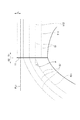
次いで、図3及び図4を参照して、前弾性部材50及び後弾性部材55の構成及びサイド接合部の変形状態について説明する。図3は、前弾性部材50及び後弾性部材55が伸長した伸長状態における使い捨ておむつ1の側面図である。図4は、使い捨ておむつを装着した状態を示した図である。
Next, the configuration of the front
なお、伸長状態とは、第1弾性部材としての後脚回り弾性部材57及び第2弾性部材としての前脚回り弾性部材51が伸長した状態であり、具体的には、使い捨ておむつを所定の円筒に装着した状態である。
The extended state is a state in which the rear leg
円筒の寸法は、以下のように設定できる。まず、使い捨ておむつを構成する外装体であって、前弾性部材と後弾性部材が配置されていない状態の外装体を用意する。この弾性部材が配置されていない状態の外装体の前側端部におけるサイド接合部11間の距離を測定する。この外装体の前側端部におけるサイド接合部11間の距離をL11とする。また、弾性部材が配置されていない状態の外装体の後側端部におけるサイド接合部11間の距離を測定する。外装体の後側端部におけるサイド接合部11間の距離をL12とする。更に、前胴回り域の前後方向の寸法を測定し、この寸法をL13とする。後胴回り域の前後方向の寸法を測定し、この寸法をL14とする。
The dimensions of the cylinder can be set as follows. First, an exterior body constituting a disposable diaper is prepared in a state where the front elastic member and the rear elastic member are not arranged. The distance between the side
外装体の前側端部におけるサイド接合部11間の距離L11と外装体の後側端部におけるサイド接合部11間の距離L12とを合計し、その合計長さ×0.8を算出する。算出した値をXとする。円筒の外周の長さは、Xとする。円筒の軸方向の長さは、L13及びL14以上とする。 The distance L11 between the side joints 11 at the front end of the exterior body and the distance L12 between the side joints 11 at the rear end of the exterior body are summed, and the total length × 0.8 is calculated. Let X be the calculated value. The length of the outer periphery of the cylinder is X. The axial length of the cylinder is set to L13 and L14 or more.
後脚回り弾性部材57は、幅方向に延びる直線状の直線部57Sと、直線部57Sよりも幅方向両外側に位置し、かつ幅方向内側から幅方向外側に向かって前後方向内側である前側から前後方向外側である後側に延びる曲線状の曲線部57Cと、を有する。
The rear leg-hole
直線部57Sは、幅方向に沿って配置され後胴回り弾性部材56と平行に配置されている。曲線部57Cは、後胴回り域S2側の脚回り開口部9に沿って配置されている。
The
後脚回り弾性部材57は、3本設けられており、後脚回り弾性部材のうち、最も脚回り開口部側に配置されている端部後脚回り弾性部材571は、幅方向に延びる仮想線FL1に対して傾斜している。一方、前脚回り弾性部材51は、2本設けられており、前脚回り弾性部材51のうち、最も脚回り開口部側に配置されている端部前脚回り弾性部材511は、幅方向に延びる仮想線FL1に沿って配置されている。
Three rear leg
よって、端部後脚回り弾性部材571と仮想線とがなす角度αは、端部前脚回り弾性部材511と仮想線とがなす角度(実施の形態では、0度)よりも大きい。本実施の形態では、後脚回り弾性部材57が第1弾性部材を構成し、前脚回り弾性部材51が第2弾性部材を構成する。
Therefore, the angle α formed between the end rear leg-hole
なお、本実施の形態の端部前脚回り弾性部材511は、幅方向に沿って配置されているが、端部前脚回り弾性部材511が幅方向に対して傾斜していてもよい。その場合、端部前脚回り弾性部材511と仮想線FL1とがなす角が、端部後脚回り弾性部材571と仮想線とがなす角度αよりも小さくなるように構成されていればよい。
In addition, although the edge part front leg periphery
また、端部第2弾性部材である端部前脚回り弾性部材511の幅方向の伸縮力は、端部第1弾性部材である端部後脚回り弾性部材571の幅方向の伸縮力より高くなるように構成されている。
Further, the elastic force in the width direction of the end front leg
幅方向の伸縮力とは、端部第2弾性部材による伸縮力のうち、幅方向に伸縮する力であり、端部第1弾性部材による伸縮力のうち、幅方向において伸縮する力である。 The expansion / contraction force in the width direction is a force that expands / contracts in the width direction among the expansion / contraction force by the end second elastic member, and is a force that expands / contracts in the width direction among the expansion / contraction force by the end first elastic member.
幅方向の伸縮力は、以下の方法によって測定することができる。 The stretching force in the width direction can be measured by the following method.
使い捨ておむつを切り取り、測定対象となるサンプルを用意する。サンプルの寸法は、幅:脇部下端部より50mmとして、長さ:腰周り方向に伸ばした状態で150mmとする。次いで、切り取ったサンプルを自然状態で引張試験機にセットする。チャック同士を繋ぐ方向が使い捨ておむつの幅方向に沿うようにサンプルをセットする。セット時のチャック間の距離は、30mmとする。伸長率が90%、すなわちチャック間が57mmになったときの引張力を求める。この引張力を、幅方向の伸縮力とする。 Cut out disposable diapers and prepare a sample to be measured. The dimensions of the sample are 50 mm from the lower end of the side part and 150 mm in the length: stretched around the waist. Next, the cut sample is set in a tensile tester in a natural state. The sample is set so that the direction connecting the chucks is along the width direction of the disposable diaper. The distance between chucks when setting is 30 mm. The tensile force when the elongation rate is 90%, that is, the distance between chucks is 57 mm is obtained. This tensile force is defined as the stretching force in the width direction.
また、本実施の形態における伸長率とは、使い捨ておむつの伸長させた伸長状態における伸長率である。また、伸長率は、例えば、以下の方法によって測定できる。 Moreover, the expansion rate in this Embodiment is an expansion rate in the extended state which the disposable diaper was extended. Further, the elongation rate can be measured, for example, by the following method.
弾性部材を伸長させた状態で製品を固定し、直線部(インナー幅方向両端部間)及び曲線部(係止の内側から前記インナー幅方向両端部)の寸法を測定する(この寸法をIとする)。前記記載した直線部及び曲線部に印を入れた後、弾性部材部分にて製品をカットする。ホットメルト等の付着物を完全に取り除いた後、ものさしにて非伸長状態の弾性部材を真直ぐに置いた状態で寸法を測定する(この寸法をIIとする)。I/IIの計算値を伸長率とする。 The product is fixed with the elastic member extended, and the dimensions of the straight part (between both ends in the inner width direction) and the curved part (both ends of the inner width direction from the inside of the locking) are measured (this dimension is I) Do). After marking the straight and curved portions described above, the product is cut at the elastic member portion. After completely removing deposits such as hot melt, the dimension is measured with a non-stretched elastic member placed straight with a ruler (this dimension is designated II). The calculated value of I / II is taken as the expansion rate.
端部後脚回り弾性部材571と仮想線とがなす角度αは、端部前脚回り弾性部材511と仮想線とがなす角度(実施の形態では、0度)よりも大きいため、端部後脚回り弾性部材571による幅方向に沿った収縮力よりも、端部前脚回り弾性部材511による幅方向に沿った収縮力が高くなり易い。
The angle α formed by the end rear leg-hole
よって、前胴回り域と後胴回り域とを接合するサイド接合部11は、脚回り開口部近傍において、比較的収縮力が高い前脚回り弾性部材51によって前胴回り域側に引き寄せられる。よって、サイド接合部の前後方向内側端部(脚回り開口部側の端部)を、前胴回り域側に引き寄せることができる。サイド接合部の前後方向内側端部(脚回り開口部側の端部)が前胴回り域と後胴回り域との間に配置されている構成と比較して、サイド接合部の前後方向内側端部と着用者との接触圧を低減することができ、着用者の装着感が向上する。
Therefore, the side
また、着用者が椅子等に座った姿勢や寝た姿勢では、使い捨ておむつの後胴回り域に着用者の体重が掛かる。そのため、サイド接合部の前後方向内側端部が後胴回り域側に引き寄せられると、サイド接合部の前後方向内側端部が身体に刺激を与えることがある。しかし、サイド接合部の前後方向内側端部を前胴回り域側に引き寄せることにより、座った姿勢や寝姿勢における刺激を抑制できる。更に、サイド接合部の前後方向内側端部を前胴回り域側に引き寄せることにより、着用者の後側に位置する脚回り開口部を広く形成でき、装着時の脚の引っかかりを抑制できる。 In addition, when the wearer is sitting on a chair or sleeping, the weight of the wearer is applied to the rear waist area of the disposable diaper. Therefore, when the front-rear inner end of the side joint is drawn toward the rear waistline region, the front-rear inner end of the side joint may irritate the body. However, it is possible to suppress stimulation in a sitting posture or a sleeping posture by pulling the front and rear inner ends of the side joints toward the front waistline region. Furthermore, by pulling the front-rear direction inner end portion of the side joint portion toward the front waistline region, a leg opening that is located on the rear side of the wearer can be widely formed, and the catching of the legs during wearing can be suppressed.
サイド接合部11を前胴回り域側に引き寄せることにより、サイド接合部を体の前後方向のラインに対して傾斜させることができる。例えば、サイド接合部が前側及び後側に寄せられていない状態では、サイド接合部の前後方向内側端部と、脚回り開口部とは略直角に交わる。このように直角に交わった状態では、サイド接合部の前後方向内側端部の刺激が更に強くなる。
By pulling the side
しかし、サイド接合部を体の前後方向のラインに対して傾斜することにより、サイド接合部の前後方向内側端部が脚回り開口部に対して直交せず、着用者の脚回りへの刺激を抑制できる。 However, by inclining the side joints with respect to the longitudinal line of the body, the front and rear inner ends of the side joints are not perpendicular to the leg opening and stimulate the wearer's legs. Can be suppressed.
また、サイド接合部の脚回り開口部側の端部が、前胴回り域側又は後胴回り域側(本実施の形態では前胴回り域側)にずれて配置されるため、サイド接合部の脚回り開口部側の端部が身体のラインに対して略垂直に配置される構成と比較して、脚周り開口部を広く形成できる。よって、装着時に脚が通しやすくなり、また装着した状態で脚の可動範囲を広く取ることができる。 In addition, since the end of the side joint portion on the leg opening side is shifted to the front waistline side or the rear waistline side (the front waistline side in this embodiment), Compared with the configuration in which the end on the opening side is arranged substantially perpendicular to the body line, the leg-hole opening can be formed wider. Therefore, the leg can be easily passed when worn, and the movable range of the leg can be widened when worn.
端部第2弾性部材としての端部前脚回り弾性部材511は、端部第1弾性部材としての端部後脚回り弾性部材571よりも脚回り開口部側に配置されている。よって、端部前脚回り弾性部材511によってサイド接合部11の脚回り開口部側の端部を前胴回り域側に引き寄せることができる。
The end front leg-holes
なお、本実施の形態では、端部前脚回り弾性部材511に隣接する前脚回り弾性部材512は、サイド接合部11において、端部後脚回り弾性部材571と重なっている。前脚回り弾性部材512と端部後脚回り弾性部材571とが重なった領域では、両弾性部材によって前胴回り域及び後胴回り域の両方にサイド接合部が引き寄せられる。しかし、前脚回り弾性部材512と端部後脚回り弾性部材571とが重なった領域よりも脚回り開口部側には、端部前脚回り弾性部材511のみが配置されており、前弾性部材50の伸縮力のみが作用する。よって、端部前脚回り弾性部材511によってサイド接合部の脚回り開口部側の端部を、前胴回り域側に引き寄せることができる。
In the present embodiment, the front leg
なお、上述した使い捨ておむつ1を構成する各部材は、例えば、特開2006−346439号公報に記載された材料を用いてもよい。
In addition, you may use the material described in Unexamined-Japanese-Patent No. 2006-346439 for each member which comprises the
上述したように、本発明の実施の形態を通じて本発明の内容を開示したが、この開示の一部をなす論述及び図面は、本発明を限定するものであると理解すべきではない。この開示から当業者には様々な代替実施の形態、実施例及び運用技術が明らかとなる。 As described above, the contents of the present invention have been disclosed through the embodiments of the present invention. However, it should not be understood that the descriptions and drawings constituting a part of this disclosure limit the present invention. From this disclosure, various alternative embodiments, examples, and operational techniques will be apparent to those skilled in the art.
本実施の形態では、前脚回り弾性部材51は、端部後脚回り弾性部材571よりも脚回り開口部側に1本配置されているが、前脚回り弾性部材51は、端部後脚回り弾性部材571よりも脚回り開口部側に2本以上配置されていてもよい。前弾性部材50によって、サイド接合部の前後方向内側端部をより効果的に引き寄せることができる。
In the present embodiment, one front leg
また、前脚回り弾性部材の伸長率と後脚回り弾性部材の伸長率とを同じ倍率で構成してもよいし、前脚回り弾性部材の伸長率を、後脚回り弾性部材の伸長率を高く構成することによって、サイド接合部の前後方向内側端部を前胴回り域側に引き寄せるように構成してもよい。 In addition, the extension rate of the front leg elastic member and the extension factor of the rear leg elastic member may be configured at the same magnification, or the extension rate of the front leg elastic member is set to be higher than that of the rear leg elastic member. By doing so, you may comprise so that the front-back direction inner side edge part of a side junction part may be drawn near to the front waistline area side.
更に、前弾性部材50の伸長率を、脚回り開口部側に向かうにつれて高くなるように構成し、後弾性部材55の伸長率を、脚回り開口部側に向うにつれて低くなるように構成し、サイド接合部の前後方向内側端部を前胴回り域側に引き寄せるように構成してもよい。
Furthermore, the extension rate of the front
また、端部前脚回り弾性部材511の伸長率を、複数の前弾性部材50のうち、端部前脚回り弾性部材511よりも前後方向外側に位置する前弾性部材の伸長率を高く構成してもよい。このように、端部前脚回り弾性部材511の伸長率を高く構成することにより、サイド接合部の脚回り開口部側の端部を効果的に幅方向にずらすことができる。
Further, even if the extension rate of the end front leg-holes
また、前脚回り弾性部材51と後脚回り弾性部材57において、太さ、本数、及び伸長率を同じ構成としてもよい。このような構成によれば、前脚回り弾性部材51と後脚回り弾性部材57の収縮力は略同じとなる。しかし、例えば、後脚回り弾性部材57が、前脚回り弾性部材51よりも幅方向に対して傾斜していることにより、幅方向における収縮力が前脚回り弾性部材51よりも低くなる。その結果、複数の前脚回り弾性部材の幅方向における伸縮力が、複数の後脚回り弾性部材の幅方向における伸縮力よりも高くなるように構成される。
Further, the front leg
また、本実施の形態及び変形例においては、サイド接合部を前胴回り域側に引き寄せるように構成しているが、この構成に限られない。複数の第1弾性部材は、前胴回り域に配置される前脚回り弾性部材であって、複数の第2弾性部材は、後胴回り域に配置される後脚回り弾性部材であってもよい。すなわち、前弾性部材50と後弾性部材55の構成を入れ替えて、サイド接合部を後胴回り域側に引き寄せるように構成してもよい。
Moreover, in this Embodiment and the modification, although it has comprised so that a side junction part may be drawn near to the front waistline area side, it is not restricted to this structure. The plurality of first elastic members may be front leg periphery elastic members disposed in the front waistline region, and the plurality of second elastic members may be rear leg periphery elastic members disposed in the rear waistline region. That is, the configuration of the front
例えば、上述した実施の形態では、パンツ型の使い捨ておむつとして説明したが、本発明は、これに限定されるものではなく、ショーツ型ナプキンであってもよい。 For example, in the above-described embodiment, the pants-type disposable diaper has been described. However, the present invention is not limited to this and may be a shorts-type napkin.
このように、本発明は、ここでは記載していない様々な実施の形態などを含むことは勿論である。従って、本発明の技術的範囲は、上述の説明から妥当な特許請求の範囲に係る発明特定事項によってのみ定められるものである。 As described above, the present invention naturally includes various embodiments that are not described herein. Accordingly, the technical scope of the present invention is defined only by the invention specifying matters according to the scope of claims reasonable from the above description.
1…使い捨ておむつ(吸収性物品)
3…ウエストギャザー
3A…ウエスト弾性部材
5…レッグギャザー
51…前脚回り弾性部材
57……後脚回り弾性部材
7…胴回りギャザー
7A…胴回り弾性部材
10…表面シート
32…防漏サイドシート
33…レッグサイド弾性部材
40…吸収体
52…直線部
53…曲線部
70F…前側外装シート
70R…後側外装シート
100…外装センターシート
S1…前胴回り域
S2…後胴回り域
S3…股下域
1. Disposable diapers (absorbent articles)
DESCRIPTION OF
Claims (3)
着用者の腹側に配置される前胴回り域と、着用者の背側に配置される後胴回り域と、前記前胴回り域と前記後胴回り域との間に位置し、着用者の股下に配置される股下域とを有し、
前記外装体の前記前胴回り域の前記幅方向外側端部と前記外装体の前記後胴回り域の前記幅方向外側端部とが接合された一対のサイド接合部が形成されることにより、前記着用者の脚が挿入される一対の脚回り開口部が設けられるパンツタイプの吸収性物品であって、
前記外装体には、前記前胴回り域又は前記後胴回り域の一方の脚回り開口部に沿って配置された複数の第1弾性部材と、前記前胴回り域又は前記後胴回り域の他方の脚回り開口部に沿って配置された複数の第2弾性部材と、が設けられており、
前記複数の第1弾性部材及び前記複数の第2弾性部材が伸長した伸長状態において、前記複数の第1弾性部材のうち最も前記脚回り開口部側に位置する端部第1弾性部材と前記幅方向に延びる仮想線とがなす角度は、前記複数の第2弾性部材のうち最も前記脚回り開口部側に位置する端部第2弾性部材と前記仮想線とがなす角度よりも大きく、
前記端部第2弾性部材の前記幅方向の伸縮力は、前記端部第1弾性部材の前記幅方向の伸縮力よりも高く、
前記端部第2弾性部材は、前記端部第1弾性部材よりも前記脚回り開口部側に配置されており、
前記複数の第1弾性部材は、前記後胴回り域に配置される後脚回り弾性部材であって、
前記複数の第2弾性部材は、前記前胴回り域に配置される前脚回り弾性部材である、吸収性物品。 Absorber having a front-rear direction extending to the front side of the body and a rear side of the body, a width direction orthogonal to the front-rear direction, and a thickness direction having an inner direction toward the wearer and an outer direction toward the opposite side to the inner direction Comprising an absorbent main body, and an exterior body disposed in the outer direction than the absorbent main body,
Positioned between the front waistline region disposed on the wearer's ventral side, the rear waistline region disposed on the wearer's back side, the front waistline region and the back waistline region, and disposed on the wearer's inseam Crotch area, and
The wear is achieved by forming a pair of side joints in which the widthwise outer end of the front waistline region of the exterior body and the widthwise outer end of the rear waistline region of the exterior body are joined. A pants-type absorbent article provided with a pair of leg-hole openings into which a person's legs are inserted,
The exterior body includes a plurality of first elastic members disposed along one leg opening of the front waistline region or the rear waistline region, and the other leg periphery of the front waistline region or the rear waistline region. A plurality of second elastic members disposed along the opening, and
In the extended state in which the plurality of first elastic members and the plurality of second elastic members are extended, the end first elastic member and the width that are located closest to the leg opening portion among the plurality of first elastic members An angle formed by an imaginary line extending in the direction is larger than an angle formed by the imaginary line and the end second elastic member positioned closest to the leg opening portion among the plurality of second elastic members,
The stretching force in the width direction of the end portion second elastic member is higher than the stretching force in the width direction of the end portion first elastic member,
The end second elastic member is disposed closer to the leg opening portion than the end first elastic member ,
The plurality of first elastic members are rear leg elastic members arranged in the rear waist area,
The plurality of second elastic members are absorbent articles that are elastic members around a front leg disposed in the front waistline region .
Priority Applications (3)
| Application Number | Priority Date | Filing Date | Title |
|---|---|---|---|
| JP2012264209A JP5887258B2 (en) | 2012-12-03 | 2012-12-03 | Absorbent articles |
| PCT/JP2013/082361 WO2014087970A1 (en) | 2012-12-03 | 2013-12-02 | Absorbent article |
| CN201380063089.XA CN104822354B (en) | 2012-12-03 | 2013-12-02 | Absorbent commodity |
Applications Claiming Priority (1)
| Application Number | Priority Date | Filing Date | Title |
|---|---|---|---|
| JP2012264209A JP5887258B2 (en) | 2012-12-03 | 2012-12-03 | Absorbent articles |
Publications (3)
| Publication Number | Publication Date |
|---|---|
| JP2014108271A JP2014108271A (en) | 2014-06-12 |
| JP2014108271A5 JP2014108271A5 (en) | 2015-10-08 |
| JP5887258B2 true JP5887258B2 (en) | 2016-03-16 |
Family
ID=50883387
Family Applications (1)
| Application Number | Title | Priority Date | Filing Date |
|---|---|---|---|
| JP2012264209A Active JP5887258B2 (en) | 2012-12-03 | 2012-12-03 | Absorbent articles |
Country Status (3)
| Country | Link |
|---|---|
| JP (1) | JP5887258B2 (en) |
| CN (1) | CN104822354B (en) |
| WO (1) | WO2014087970A1 (en) |
Families Citing this family (5)
| Publication number | Priority date | Publication date | Assignee | Title |
|---|---|---|---|---|
| JP6230497B2 (en) * | 2014-06-27 | 2017-11-15 | ユニ・チャーム株式会社 | Disposable pants-type diapers |
| JP6914638B2 (en) * | 2016-11-02 | 2021-08-04 | 株式会社リブドゥコーポレーション | Absorbent article and manufacturing method of absorbent article |
| JP2020058768A (en) * | 2018-11-26 | 2020-04-16 | ユニ・チャーム株式会社 | Absorbent article |
| KR102678055B1 (en) * | 2018-10-12 | 2024-06-24 | 유니챰 가부시키가이샤 | Absorbent article |
| JP7495239B2 (en) * | 2020-02-21 | 2024-06-04 | 花王株式会社 | Pants-type disposable diapers |
Family Cites Families (4)
| Publication number | Priority date | Publication date | Assignee | Title |
|---|---|---|---|---|
| JP3696115B2 (en) * | 2001-04-06 | 2005-09-14 | ユニ・チャーム株式会社 | Disposable diapers |
| CN102858298B (en) * | 2010-04-19 | 2015-01-14 | 尤妮佳股份有限公司 | Absorbent article |
| JP5466072B2 (en) * | 2010-04-19 | 2014-04-09 | ユニ・チャーム株式会社 | Absorbent articles |
| CN202386859U (en) * | 2011-12-08 | 2012-08-22 | 尤妮佳股份有限公司 | Absorptive object |
-
2012
- 2012-12-03 JP JP2012264209A patent/JP5887258B2/en active Active
-
2013
- 2013-12-02 CN CN201380063089.XA patent/CN104822354B/en active Active
- 2013-12-02 WO PCT/JP2013/082361 patent/WO2014087970A1/en active Application Filing
Also Published As
| Publication number | Publication date |
|---|---|
| JP2014108271A (en) | 2014-06-12 |
| CN104822354B (en) | 2017-09-01 |
| CN104822354A (en) | 2015-08-05 |
| WO2014087970A1 (en) | 2014-06-12 |
Similar Documents
| Publication | Publication Date | Title |
|---|---|---|
| JP6153338B2 (en) | Pants-type diapers for young children | |
| JP5822818B2 (en) | Absorbent articles | |
| JP6192003B2 (en) | Elastic structure of absorbent articles | |
| TWI480033B (en) | Pants charge absorbent | |
| JP6118703B2 (en) | Absorbent articles | |
| JP6427535B2 (en) | Absorbent articles | |
| JP2011120626A (en) | Pants type absorbent article | |
| JP5887258B2 (en) | Absorbent articles | |
| JP6452123B2 (en) | Elastic structure of absorbent articles | |
| JP2007097920A (en) | Disposable diaper | |
| JP4920892B2 (en) | Disposable pants-type wearing articles | |
| JP2014198178A (en) | Expansion and contraction structure of absorbent article | |
| KR20150128685A (en) | Disposable underwear-style diaper | |
| JP5250407B2 (en) | Disposable pants-type diaper and method for manufacturing the same | |
| JP2019030551A (en) | Underpants type absorbent article | |
| TW201630581A (en) | Disposable worn article | |
| JP5721987B2 (en) | Absorbent articles | |
| JP6296761B2 (en) | Disposable wearing items | |
| TW201713290A (en) | Disposable wearable article | |
| JP6255203B2 (en) | Absorbent articles | |
| JP6236420B2 (en) | Absorbent articles | |
| JP7366597B2 (en) | absorbent articles | |
| JP7438870B2 (en) | absorbent articles | |
| WO2023175996A1 (en) | Absorbent article | |
| WO2021033408A1 (en) | Underpants-type absorbent article |
Legal Events
| Date | Code | Title | Description |
|---|---|---|---|
| RD01 | Notification of change of attorney |
Free format text: JAPANESE INTERMEDIATE CODE: A7421 Effective date: 20140603 |
|
| A521 | Request for written amendment filed |
Free format text: JAPANESE INTERMEDIATE CODE: A523 Effective date: 20150525 |
|
| A621 | Written request for application examination |
Free format text: JAPANESE INTERMEDIATE CODE: A621 Effective date: 20150811 |
|
| A521 | Request for written amendment filed |
Free format text: JAPANESE INTERMEDIATE CODE: A523 Effective date: 20150819 |
|
| A871 | Explanation of circumstances concerning accelerated examination |
Free format text: JAPANESE INTERMEDIATE CODE: A871 Effective date: 20150819 |
|
| A975 | Report on accelerated examination |
Free format text: JAPANESE INTERMEDIATE CODE: A971005 Effective date: 20150903 |
|
| A131 | Notification of reasons for refusal |
Free format text: JAPANESE INTERMEDIATE CODE: A131 Effective date: 20151006 |
|
| A521 | Request for written amendment filed |
Free format text: JAPANESE INTERMEDIATE CODE: A523 Effective date: 20151130 |
|
| TRDD | Decision of grant or rejection written | ||
| A01 | Written decision to grant a patent or to grant a registration (utility model) |
Free format text: JAPANESE INTERMEDIATE CODE: A01 Effective date: 20160202 |
|
| A61 | First payment of annual fees (during grant procedure) |
Free format text: JAPANESE INTERMEDIATE CODE: A61 Effective date: 20160215 |
|
| R150 | Certificate of patent or registration of utility model |
Ref document number: 5887258 Country of ref document: JP Free format text: JAPANESE INTERMEDIATE CODE: R150 |
|
| R250 | Receipt of annual fees |
Free format text: JAPANESE INTERMEDIATE CODE: R250 |
|
| R250 | Receipt of annual fees |
Free format text: JAPANESE INTERMEDIATE CODE: R250 |
|
| R250 | Receipt of annual fees |
Free format text: JAPANESE INTERMEDIATE CODE: R250 |
|
| R250 | Receipt of annual fees |
Free format text: JAPANESE INTERMEDIATE CODE: R250 |
|
| R250 | Receipt of annual fees |
Free format text: JAPANESE INTERMEDIATE CODE: R250 |
|
| R250 | Receipt of annual fees |
Free format text: JAPANESE INTERMEDIATE CODE: R250 |