JP5886085B2 - Stage device and control method of stage device - Google Patents
Stage device and control method of stage device Download PDFInfo
- Publication number
- JP5886085B2 JP5886085B2 JP2012049173A JP2012049173A JP5886085B2 JP 5886085 B2 JP5886085 B2 JP 5886085B2 JP 2012049173 A JP2012049173 A JP 2012049173A JP 2012049173 A JP2012049173 A JP 2012049173A JP 5886085 B2 JP5886085 B2 JP 5886085B2
- Authority
- JP
- Japan
- Prior art keywords
- lift pin
- driving means
- fixed
- work table
- stage
- Prior art date
- Legal status (The legal status is an assumption and is not a legal conclusion. Google has not performed a legal analysis and makes no representation as to the accuracy of the status listed.)
- Expired - Fee Related
Links
Images


Landscapes
- Container, Conveyance, Adherence, Positioning, Of Wafer (AREA)
Description
本発明は、例えば、フラットパネルディスプレイ(FPD)や半導体基板等の板状の作業対象物の製造や検査に利用されるステージ装置およびステージ装置の制御方法に関する。 The present invention relates to a stage apparatus used for manufacturing and inspecting a plate-like work object such as a flat panel display (FPD) and a semiconductor substrate, and a control method for the stage apparatus.
従来、ステージ装置として、水平方向に移動可能なステージと、当該ステージ上に固定され、作業対象物であるワークを水平載置するためのワークテーブルとを具備する、特許文献1に記載のステージ装置が知られている。このステージ装置においては、ワークテーブルの裏面側にリフトピンユニットが配置され、リフトピンユニットにはリフトピンが立設されている。ワークテーブルには上下方向に延在する複数のピン穴が設けられており、複数のピン穴のそれぞれにリフトピンが挿入される。また、リフトピンユニットが備えるモータの回転運動をリフトピンの上下運動に変換することにより、リフトピンは昇降可能に構成されている。そして、ワークをワークテーブル上に載置する際には、まずリフトピンを上昇させ、上昇したリフトピンにワークを載せた後にリフトピンをワークテーブルのピン穴の中まで下降させることにより、ワークをワークテーブル上に水平載置する。
2. Description of the Related Art Conventionally, as a stage device, a stage device described in
しかしながら、上記のステージ装置にあっては、リフトピンを下降させてワークをワークテーブルに水平載置する際に、ワークとワークテーブルの間に空気がたまってしまう場合があり、この空気を抜くには時間がかかり、ワークを交換するための作業時間が長くなってしまう。 However, in the above stage apparatus, when the work piece is horizontally placed on the work table by lowering the lift pins, air may accumulate between the work and the work table. It takes time, and the work time for exchanging the workpiece becomes long.
本発明は、このような課題を解決するためになされたものであり、ワークを交換するための作業時間を短縮できるステージ装置およびステージ装置の制御方法を提供することを目的とする。 The present invention has been made to solve such a problem, and an object of the present invention is to provide a stage apparatus and a stage apparatus control method capable of reducing the work time for exchanging the workpiece.
本発明に係るステージ装置は、水平方向に移動可能なステージと、ステージ上に固定されるワークテーブルと、ワークテーブルの裏面側に配置されたリフトピンユニットと、を具備し、リフトピンユニットは、ワークテーブルの裏面側に固定される第1駆動手段と、第1駆動手段によって支持されると共に上下方向に駆動され、複数の第1のリフトピンを支持するベース部材と、ベース部材に固定される第2駆動手段と、第2駆動手段によって支持されると共に上下方向に駆動され、複数の第2のリフトピンを支持するビーム部材と、を具備し、第2駆動手段は、ベース部材に固定されるシリンダと、シリンダ内に設けられたピストンと、傾斜するカム溝を有し、ピストンに連結されて水平方向に駆動されるカム板と、ベース部材に固定され、カム板の水平方向の移動をガイドするリニアガイドと、ビーム部材に固定され、カム溝に挿入されるカムフォロワと、ベース部材に固定され、ビーム部材の上下方向の移動を案内するためのブッシュと、ビーム部材から鉛直方向に延び、ブッシュを上下方向に貫通するシャフトと、を有する。 A stage apparatus according to the present invention includes a stage movable in a horizontal direction, a work table fixed on the stage, and a lift pin unit disposed on the back side of the work table. The lift pin unit is a work table. A first driving means fixed to the back surface side of the first base, a base member supported by the first driving means and driven in the vertical direction to support the plurality of first lift pins, and a second driving fixed to the base member And a beam member supported by the second driving means and driven in the vertical direction to support the plurality of second lift pins , and the second driving means includes a cylinder fixed to the base member, A piston provided in the cylinder, a cam plate having an inclined cam groove, connected to the piston and driven in the horizontal direction, and fixed to the base member A linear guide for guiding the horizontal movement of the cam plate, a cam follower fixed to the beam member and inserted into the cam groove, a bush fixed to the base member and guiding the vertical movement of the beam member; A shaft extending in a vertical direction from the beam member and penetrating the bush in the vertical direction.
また、本発明に係るステージ装置の制御方法は、上記ステージ装置を制御する方法であって、第1駆動手段によってベース部材を上昇させて、第1および第2のリフトピンによってワークを水平状態で受け取るステップと、第2駆動手段によってビーム部材を上昇させてワークを傾斜させるステップと、第2駆動手段によってビーム部材を上昇させたまま第1駆動手段によってベース部材を下降させるステップと、第2駆動手段によってビーム部材を下降させることによりワークをワークテーブル上に水平載置するステップと、を含む。 The stage apparatus control method according to the present invention is a method for controlling the stage apparatus, wherein the base member is raised by the first driving means and the workpiece is received in a horizontal state by the first and second lift pins. A step of tilting the workpiece by raising the beam member by the second driving means, a step of lowering the base member by the first driving means while raising the beam member by the second driving means, and a second driving means And horizontally placing the work on the work table by lowering the beam member.
このようなステージ装置及びステージ装置の制御方法によれば、第1駆動手段によってベース部材、ビーム部材、ならびに第1および第2のリフトピンを上昇させてワークを水平状態で受け取った後、第2駆動手段によってビーム部材および第2のリフトピンを上昇させてワークを傾斜させ、その後、第2駆動手段によってビーム部材および第2のリフトピンを上昇させたまま第1駆動手段によってベース部材、ビーム部材、ならびに第1および第2のリフトピンを下降させワークを傾斜させた状態で当該ワークの一端側をワークテーブル上に着け、第2駆動手段によってビーム部材および第2のリフトピンを下降させてワークをワークテーブル上に水平載置することができる。したがって、ワークとワークテーブルの間にたまる空気を押し出すことができ、ワークを交換するための作業時間を短縮することができる。また、ピストンの水平方向の運動を、傾斜するカム溝を有するカム板を用いてビーム部材の上下運動に変換することができるため、第2駆動手段のサイズを小さくすることができると共に、カム板の水平方向の移動をガイドするリニアガイドならびにビーム部材の上下方向の移動を案内するブッシュおよびブッシュを上下方向に貫通するシャフトにより、円滑にビーム部材を上下動させることができる。 According to such a stage apparatus and a method for controlling the stage apparatus, the first driving means raises the base member, the beam member, and the first and second lift pins to receive the workpiece in a horizontal state, and then performs the second driving. The beam member and the second lift pin are raised by the means to incline the workpiece, and then the base member, the beam member, and the first drive means are moved by the first drive means while the beam member and the second lift pin are raised by the second drive means. In a state where the first and second lift pins are lowered and the work is inclined, one end side of the work is put on the work table, and the beam member and the second lift pin are lowered by the second driving means to place the work on the work table. Can be placed horizontally. Therefore, the air which accumulates between a workpiece | work and a work table can be pushed out, and the working time for exchanging a workpiece | work can be shortened. Further, since the horizontal movement of the piston can be converted into the vertical movement of the beam member using a cam plate having an inclined cam groove, the size of the second drive means can be reduced, and the cam plate The beam member can be smoothly moved up and down by the linear guide that guides the horizontal movement of the beam, the bush that guides the vertical movement of the beam member, and the shaft that passes through the bush in the vertical direction.
本発明に係るステージ装置およびステージ装置の制御方法によれば、ワークを交換するための作業時間を短縮することができる。 According to the stage apparatus and the method for controlling the stage apparatus according to the present invention, the working time for exchanging the workpiece can be shortened.
以下、図面を参照しつつ本発明に係るステージ装置及びステージ装置の制御方法の好適な実施形態について詳細に説明する。なお、X軸及びY軸は水平面上で互いに90度をなし、鉛直方向をZ軸方向と定め、以下必要な場合にX軸、Y軸、Z軸を用いる。 DESCRIPTION OF EMBODIMENTS Hereinafter, preferred embodiments of a stage apparatus and a method for controlling a stage apparatus according to the present invention will be described in detail with reference to the drawings. The X axis and the Y axis are 90 degrees on the horizontal plane, the vertical direction is defined as the Z axis direction, and the X axis, the Y axis, and the Z axis are used below when necessary.
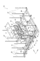
図1及び図2に示すように、XYステージ装置(ステージ装置)1は、ベース2上でX軸方向に離間して並設されてY軸方向に延在する一対の石定盤3,4と、石定盤3,4に沿ってY軸方向へ移動するY軸ステージ6と、Y軸ステージ6の駆動部として機能する一対のY軸リニアモータ7,8と、Y軸ステージ6上でX軸方向へ移動するX軸ステージ(ステージ)9と、X軸ステージ9の駆動部として機能するX軸リニアモータ(図示せず)と、石定盤3,4上でエアベアリング5によって支持されると共に、X軸ステージ9の上方に配置されて、多数のピン穴70が設けられたワークテーブル10とを具備している。ワークテーブル10は、その上面に、フラットパネルディスプレイ(FPD)や半導体基板等の板状の作業対象物であるワークを水平載置するためのテーブルである。
As shown in FIGS. 1 and 2, an XY stage device (stage device) 1 is a pair of
一方の石定盤3は、角柱状の石材からなり、その上面には平面加工が施されることによって、図2に示すように、Y軸ステージ6のY軸リフトエアベアリング14が滑走するための上面側滑走面3aが形成されている。また、Y軸方向に沿って延在する石定盤3の両側面にも、上面側滑走面3aと同様に平面加工が施されることによって、Y軸ステージ6のY軸ヨーエアベアリング17が滑走するための側面側滑走面3b,3cが形成されている。同様に、他方の石定盤4の上面及び両側面にも、平面加工が施されることによって上面側滑走面4a及び側面側滑走面4b,4cが形成されている。
One
石定盤3,4上を滑走するY軸ステージ6は、石定盤3,4にガイドされながらそれぞれY軸方向へ移動する一対のY軸スライダ12,13と、Y軸スライダ12,13を石定盤3,4の上面側滑走面3a,4aに対して非接触状態でそれぞれZ軸方向に支持するためのY軸リフトエアベアリング14と、Y軸スライダ12,13を石定盤3,4の側面側滑走面3b,3c,4b,4cに対して非接触状態でそれぞれ水平方向に支持するためのY軸ヨーエアベアリング17と、Y軸スライダ12,13に固定されて、Y軸スライダ12,13を架け渡すようにX軸方向へ延在しY軸方向に離間した一対のガイド部材19,19とを備えている。以上のような構成により、Y軸ステージ6は、水平方向に移動可能とされている。
The Y-axis stage 6 that slides on the
Y軸スライダ12,13上に配置されたX軸ステージ9は、ガイド部材19,19に沿ってX軸方向へ移動するX軸スライダ33と、X軸スライダ33を石定盤3,4の上面側滑走面3a,4aに対して非接触状態でそれぞれZ軸方向に支持するためのX軸リフトエアベアリング(図示せず)と、X軸スライダ33を水平方向に支持するためのX軸ヨーエアベアリング(図示せず)と、X軸スライダ33とワークテーブル10との間に配置されて、ワークテーブル10をZ軸周りに回動させるθテーブル37とを備えている。なお、Xスライダ33を石定盤3,4上で滑走させるために、前述したX軸リフトエアベアリング(図示せず)は、Y軸スライダ12,13に設けられた長穴21,22を上下に挿通している。以上のような構成により、X軸ステージ9は、水平方向に移動可能とされている。
The X-axis stage 9 disposed on the Y-
次に、ワークテーブル10の裏面10a側に配置されて、ワーク(例えば半導体基板)を昇降させるために利用されるリフトピンユニット50について詳細に説明する。
Next, the
図3および図4に示すように、リフトピンユニット50は、ワークテーブルとして機能するワークテーブル10の裏面10aにボルト(図示せず)で固定される取付けプレート51を備えている。取付けプレート51には、ワークテーブル10にボルトで固定するための複数の取付穴51aが設けられ、取付けプレート51の四隅には、各支柱52の上端が固定され、各支柱52は、取付けプレート51から垂下するように延在している。
As shown in FIGS. 3 and 4, the
さらに、取付けプレート51の裏面には、ブラケットを介してモータ54が固定され、モータ54の出力軸54a(図7参照)には、カップリング56を介してネジ軸57が取り付けられている。このネジ軸57は、取付けプレート51の下方で水平方向に延在し、ネジ軸57にはナット部58が螺合されている。そして、ナット部58のスムーズな水平移動を達成させるために、ネジ軸57とナット部58とでボールネジが構成されている。
Further, a
さらに、取付けプレート51の裏面には、図6および図7に示すように、水平方向に延在する2本のガイドレール60がボルトによって固定され、各ガイドレール60には、摺動自在なスライダ61がそれぞれ装着されている。左右一対のスライダ61の間に配置されたナット部58と各スライダ61とは、ボルトによって連結プレート62(図7参照)に固定されている。従って、ネジ軸57の回転によりナット部58が直線的に進退すると、このナット部58の移動に追従して、連結プレート62を、ガイドレール60の案内によって水平方向に直線的に進退させることができる。
Further, as shown in FIGS. 6 and 7, two
また、この連結プレート62の両端には、図4および図13〜図15に示すように、左右一対の第1カム板63がボルトによって固定され、鉛直方向に延在する各第1カム板63は、連結プレート62の移動に追従して水平方向に直線的に進退する。各第1カム板63には、斜めに直線的又は曲線的(ここでは直線的)に延在するカム溝63aがV軸方向に並設され、各カム溝63aには、従動ローラ(従動部)64がそれぞれ進入している(図14参照)。
Further, as shown in FIGS. 4 and 13 to 15, a pair of left and right
なお、図4および図7に示すように、モータ54の回転をリフトピンベース(ベース部材:詳しくは後述)66の上下動に変換することによってリフトピンベース66を上下方向に駆動する第1駆動機構(第1駆動手段)S1は、モータ54と、モータ54の出力軸54aとして延在するネジ軸57と、ネジ軸57に螺合されたナット部58と、ナット部58に連結された第1カム板63と、第1カム板63に形成されたカム溝63aに沿って移動すると共に、第1のリフトピン67を支持するリフトピンベース66に連結された従動ローラ64とを備えている。
As shown in FIGS. 4 and 7, a first drive mechanism that drives the
リフトピンベース66は、長さの異なる複数のフレームFによって略格子状に組立てられたものであり、これに各従動ローラ64の支軸が固定され、各従動ローラ64が各カム溝63aに進入している。リフトピンベース66の所定位置には、複数の第1のリフトピン67の下端が固定されている。第1のリフトピン67は、前述したピン穴70に対応する位置に立設されている。さらに、取付けプレート51から垂下するように延在している各支柱52には、上下方向に延在するガイドレール68がボルトによってそれぞれ固定されている。各ガイドレール68には、図3および図13に示すように、摺動自在なスライダ69がそれぞれ装着され、各スライダ69は、リフトピンベース66に固定されている。
The
従って、カム板63が水平方向に進退すると、カム溝63aの移動に伴って従動ローラ64が上下動し、ガイドレール68の案内によってリフトピンベース66ならびに第1のリフトピン67および後述の第2のリフトピン78を円滑に上下動させることができる(図13及び図15参照)。
Therefore, when the
ここで、図8、図9および図10を参照して、第2駆動機構(第2駆動手段)S2について説明する。なお、図が煩雑になることを避けるため、図8においては、第2のリフトピン78を昇降ビーム77から取り外した状態を示している。また、以下の説明においては、水平方向のうちの一方向をU軸とし、水平面内においてU軸方向に直交する方向をV軸方向と定める。第2駆動機構S2は、前述した第1駆動機構S1により昇降するリフトピンベース66に固定されたシリンダ71と、シリンダ71内に設けられるピストンと、ピストンに連結される第2カム板(カム板)73と、第1のリフトピン67と同様に上下方向に延びる第2のリフトピン78を支持する昇降ビーム(ビーム部材)77に固定されたカムフォロワ74と、リフトピンベース66に固定されるブッシュ79と、ブッシュ79を上下方向に貫通するシャフト80と、を有する。本実施形態のXYステージ装置1には、第2駆動機構S2がV軸方向に離間して2組設けられている。
Here, the second drive mechanism (second drive means) S2 will be described with reference to FIG. 8, FIG. 9, and FIG. In addition, in order to avoid that a figure becomes complicated, in FIG. 8, the state which removed the
リフトピンベース66を構成し、U軸方向に延在するベースビーム66aには、シリンダ71がU軸方向に延びるようにして固定されている。シリンダ71内のピストンには、水平方向に移動可能な第2カム板73が連結されている。第2カム板73は、傾斜するカム溝73aを有している。
A
第2カム板73には、スライダ76が固定されている。また、ベースビーム66aには、ベースビーム66aに沿う方向にリニアガイド75が延在し固定されている。スライダ76は、リニアガイド75に沿って案内されながら水平移動することができる。このようにして、リニアガイド75は、第2カム板73の水平方向の移動をガイドする。
A
第2カム板73のカム溝73aには、カムフォロワ74が挿入されている。カムフォロワ74は、支軸の回りに回転自在なローラである。このカムフォロワ74の支軸には、ベースビーム66aに対して平行に延びる昇降ビーム77が固定されている。すなわち、この昇降ビーム77は、カムフォロワ74、カム溝73a、第2カム板73およびシリンダ71を介してベースビーム66aに支持されている。昇降ビーム77の所定位置には、複数の第2のリフトピン78の下端が固定されている。第2のリフトピン78は、前述したピン穴70に対応する位置に立設されている。さらに、昇降ビーム77には、鉛直方向に延びるシャフト80が固定されている。このシャフト80は、ベースビーム66aに固定されたブッシュ79を上下方向に貫通する(図10参照)。したがって、ブッシュ79は、シャフト80を介して昇降ビーム77の上下方向の移動を案内する。
A
ワークテーブル10には、前述したようにピン穴70(図1、図13〜図15参照)が形成され、各ピン穴70内に第1のリフトピン67および第2のリフトピン78が挿通し、リフトピンベース66および昇降ビーム77の上下動によってワークテーブル10から出没させることができる。更に、図1に示すように、各リフトピンユニット50は、ワークテーブル10の裏面10aの4カ所(二点鎖線で囲まれた領域)にボルトによって固定されている。
As described above, the work table 10 is formed with the pin holes 70 (see FIGS. 1 and 13 to 15), and the first lift pins 67 and the second lift pins 78 are inserted into the respective pin holes 70. The
以上のように構成される第2駆動機構S2の動作について、図11および図12を参照して説明する。図11は、第2駆動機構S2を用いて昇降ビーム77および第2のリフトピン78を下降させた状態を示す正面図である。図12は、第2駆動機構S2を用いて昇降ビーム77および第2のリフトピン78を上昇させた状態を示す正面図である。
The operation of the second drive mechanism S2 configured as described above will be described with reference to FIGS. FIG. 11 is a front view showing a state in which the elevating
図11に示すように、シリンダ71に設けられたピストンによってピストンに連結された第2カム板73が引き込まれると、それに伴ってカムフォロワ74が、傾斜するカム溝73aに沿って下降する。そして、カムフォロワ74の下降に伴って、カムフォロワ74の支軸に固定された昇降ビーム77および第2のリフトピン78が下降する。また、図12に示すように、シリンダ71に設けられたピストンによってピストンに連結された第2カム板73が押し出されると、それに伴ってカムフォロワ74が、傾斜するカム溝73aに沿って上昇する。そして、カムフォロワ74の上昇に伴って、カムフォロワ74の支軸に固定された昇降ビーム77および第2のリフトピン78が上昇する。
As shown in FIG. 11, when the
次に、図13〜図15を参照して、上述の通りに構成されるXYステージ装置1を用いてワークをワークテーブル10に載置するためのXYステージ装置1の制御方法を説明する。
Next, a control method of the
まず、図13に示すように、第1駆動機構S1によってリフトピンベース66を上昇させて、第1のリフトピン67および第2のリフトピン78をワークテーブル10の上面から突出させる。このとき、第2駆動機構S2によって第2のリフトピン78の上端と第1のリフトピン67の上端の高さを同一としておく。そして、第1のリフトピン67および第2のリフトピン78の上端にワークKを水平載置して、第1のリフトピン67および第2のリフトピン78にワークKを受け取らせる。
First, as shown in FIG. 13, the
次に、図14に示すように、第2駆動機構S2によって昇降ビーム77を上昇させ、第2のリフトピン78の上端を第1のリフトピン67の上端よりも高い位置に移動させることによって、ワークKを傾斜させる。ここでは、外側(図示右側)の第2駆動機構S2の第2のリフトピン78の上端の高さを、内側(図示左側)の第2駆動機構S2の第2のリフトピン78の上端の高さよりも高くした状態とする。
Next, as shown in FIG. 14, the
そして、第2駆動機構S2によって昇降ビーム77を上昇させたまま、第1駆動機構S1によってリフトピンベース66を下降させる。
Then, the
そして、さらにリフトピンベース66を、第1のリフトピン67の上端がワークテーブル10の上面よりも下に位置し、かつ第2のリフトピン78の上端がワークテーブル10の上面よりも上に位置するようになるまで下降させる。このようにして、ワークKを傾斜させた状態で、ワークKの一端側をワークテーブル10の上面に着ける。
Further, the
最後に、図15に示すように、第2駆動機構S2によって昇降ビーム77を下降させることにより、第2のリフトピン78をピン穴70内に収容して、ワークKをワークテーブル10上に水平載置する。
Finally, as shown in FIG. 15, the
以上で説明したXYステージ装置1およびXYステージ装置1の制御方法によれば、第1駆動機構S1によってリフトピンベース66、昇降ビーム77、ならびに第1のリフトピン67および第2のリフトピン78を上昇させてワークKを水平状態で受け取った後、第2駆動機構S2によって昇降ビーム77および第2のリフトピン78を上昇させてワークKを傾斜させ、その後、第2駆動機構S2によって昇降ビーム77および第2のリフトピン78を上昇させたまま第1駆動手段によってリフトピンベース66、昇降ビーム77、ならびに第1のリフトピン67および第2のリフトピン78を下降させワークKを傾斜させた状態でワークKの一端側をワークテーブル10上に着け、第2駆動機構S2によって昇降ビーム77および第2のリフトピン78を下降させてワークKをワークテーブル10上に水平載置することができる。したがって、ワークKとワークテーブル10の間にたまる空気を押し出すことができ、ワークKを交換するための作業時間を短縮することができる。
According to the
1…XYステージ装置(ステージ装置)、9…X軸ステージ(ステージ)、10…ワークテーブル、50…リフトピンユニット、66…リフトピンベース(ベース部材)、67…第1のリフトピン、71…シリンダ、73…第2カム板(カム板)、73a…カム溝、74…カムフォロワ、75…リニアガイド、77…昇降ビーム(ビーム部材)、78…第2のリフトピン、79…ブッシュ、80…シャフト、S1…第1駆動機構(第1駆動手段)、S2…第2駆動機構(第2駆動手段)。
DESCRIPTION OF
Claims (2)
前記ステージ上に固定されるワークテーブルと、
前記ワークテーブルの裏面側に配置されたリフトピンユニットと、を具備し、
前記リフトピンユニットは、
前記ワークテーブルの裏面側に固定される第1駆動手段と、
前記第1駆動手段によって支持されると共に上下方向に駆動され、複数の第1のリフトピンを支持するベース部材と、
前記ベース部材に固定される第2駆動手段と、
前記第2駆動手段によって支持されると共に上下方向に駆動され、複数の第2のリフトピンを支持するビーム部材と、を具備し、
前記第2駆動手段は、
前記ベース部材に固定されるシリンダと、
前記シリンダ内に設けられたピストンと、
傾斜するカム溝を有し、前記ピストンに連結されて水平方向に駆動されるカム板と、
前記ベース部材に固定され、前記カム板の水平方向の移動をガイドするリニアガイドと、
前記ビーム部材に固定され、前記カム溝に挿入されるカムフォロワと、
前記ベース部材に固定され、前記ビーム部材の上下方向の移動を案内するためのブッシュと、
前記ビーム部材から鉛直方向に延び、前記ブッシュを上下方向に貫通するシャフトと、
を有するステージ装置。 A stage that can move horizontally,
A work table fixed on the stage;
A lift pin unit disposed on the back side of the work table,
The lift pin unit is
First driving means fixed to the back side of the work table;
A base member supported by the first driving means and driven in the vertical direction to support the plurality of first lift pins;
Second driving means fixed to the base member;
A beam member supported by the second driving means and driven in the vertical direction to support a plurality of second lift pins;
The second driving means includes
A cylinder fixed to the base member;
A piston provided in the cylinder;
A cam plate having an inclined cam groove and connected to the piston and driven in a horizontal direction;
A linear guide fixed to the base member and guiding the horizontal movement of the cam plate;
A cam follower fixed to the beam member and inserted into the cam groove;
A bush fixed to the base member for guiding the vertical movement of the beam member;
A shaft extending vertically from the beam member and penetrating the bush vertically.
Luz stage device having a.
前記第1駆動手段によって前記ベース部材を上昇させて、前記第1および第2のリフトピンによってワークを水平状態で受け取るステップと、
前記第2駆動手段によって前記ビーム部材を上昇させて前記ワークを傾斜させるステップと、
前記第2駆動手段によって前記ビーム部材を上昇させたまま前記第1駆動手段によって前記ベース部材を下降させるステップと、
前記第2駆動手段によって前記ビーム部材を下降させることにより前記ワークを前記ワークテーブル上に水平載置するステップと、を含む、ステージ装置の制御方法。 It is a control method of the stage apparatus according to claim 1,
Raising the base member by the first driving means and receiving the workpiece in a horizontal state by the first and second lift pins;
Raising the beam member by the second driving means to incline the workpiece;
Lowering the base member by the first driving means while raising the beam member by the second driving means;
And a step of horizontally placing the work on the work table by lowering the beam member by the second driving means.
Priority Applications (1)
| Application Number | Priority Date | Filing Date | Title |
|---|---|---|---|
| JP2012049173A JP5886085B2 (en) | 2012-03-06 | 2012-03-06 | Stage device and control method of stage device |
Applications Claiming Priority (1)
| Application Number | Priority Date | Filing Date | Title |
|---|---|---|---|
| JP2012049173A JP5886085B2 (en) | 2012-03-06 | 2012-03-06 | Stage device and control method of stage device |
Publications (2)
| Publication Number | Publication Date |
|---|---|
| JP2013187237A JP2013187237A (en) | 2013-09-19 |
| JP5886085B2 true JP5886085B2 (en) | 2016-03-16 |
Family
ID=49388456
Family Applications (1)
| Application Number | Title | Priority Date | Filing Date |
|---|---|---|---|
| JP2012049173A Expired - Fee Related JP5886085B2 (en) | 2012-03-06 | 2012-03-06 | Stage device and control method of stage device |
Country Status (1)
| Country | Link |
|---|---|
| JP (1) | JP5886085B2 (en) |
Families Citing this family (2)
| Publication number | Priority date | Publication date | Assignee | Title |
|---|---|---|---|---|
| JP6573813B2 (en) * | 2015-09-30 | 2019-09-11 | ファスフォードテクノロジ株式会社 | Die bonder and semiconductor device manufacturing method |
| CN113911735B (en) * | 2021-11-19 | 2023-06-27 | 博众精工科技股份有限公司 | Feeding equipment |
Family Cites Families (7)
| Publication number | Priority date | Publication date | Assignee | Title |
|---|---|---|---|---|
| JP2005072279A (en) * | 2003-08-25 | 2005-03-17 | Seiko Epson Corp | Pre-alignment device, workpiece table, droplet discharging device equipped with it, method of manufacturing electrooptic device, electrooptic device, and electronic equipment |
| JP2006073876A (en) * | 2004-09-03 | 2006-03-16 | Seiko Epson Corp | Lifter mechanism, liquid-drop discharge device comprising it, electro-optical device, manufacturing method thereof, and electronic apparatus |
| JP4692131B2 (en) * | 2005-08-04 | 2011-06-01 | 株式会社ニコン | Stage apparatus and exposure apparatus |
| US7988817B2 (en) * | 2006-11-10 | 2011-08-02 | Adp Engineering Co., Ltd. | Lift pin driving device and a flat panel display manufacturing apparatus having same |
| JP2009004545A (en) * | 2007-06-21 | 2009-01-08 | Dainippon Screen Mfg Co Ltd | Substrate mounting apparatus and substrate treating equipment |
| JP5047859B2 (en) * | 2008-03-31 | 2012-10-10 | 住友重機械工業株式会社 | Lift pin unit and XY stage apparatus having the same |
| TW201005825A (en) * | 2008-05-30 | 2010-02-01 | Panasonic Corp | Plasma processing apparatus and method |
-
2012
- 2012-03-06 JP JP2012049173A patent/JP5886085B2/en not_active Expired - Fee Related
Also Published As
| Publication number | Publication date |
|---|---|
| JP2013187237A (en) | 2013-09-19 |
Similar Documents
| Publication | Publication Date | Title |
|---|---|---|
| US10071864B2 (en) | Pallet carrying apparatus and pallet carrying method | |
| CN102147375A (en) | Dual-working-platform surface fault automatic detector for flexible printed circuit | |
| JP6080973B2 (en) | Machine tool equipment | |
| KR102017097B1 (en) | Pallet conveying device | |
| WO2016145781A1 (en) | Device for taking and placing plate-shaped product | |
| JP7561163B2 (en) | Automatic loading and unloading device and automatic loading system for chip material with tray | |
| JP2016117117A (en) | Circulation type pallet conveyance apparatus | |
| JP5047859B2 (en) | Lift pin unit and XY stage apparatus having the same | |
| JP5886085B2 (en) | Stage device and control method of stage device | |
| CN213135676U (en) | Welding tool table applied to automatic welding system | |
| CN105023869A (en) | Semi-automatic aligning machine | |
| CN107234612B (en) | Cell-phone screen presss from both sides and gets unit and cell-phone screen presss from both sides and gets positioner | |
| JP6670124B2 (en) | Work lifting device, work lifting method and work processing method | |
| CN109262174B (en) | Three-dimensional one-stop type elevator derrick manufacturing tool platform | |
| CN110712988B (en) | Accumulating roller way storage type tool switching machine | |
| CN209319088U (en) | A kind of one-stop elevator well frame fabricating tools platform of solid | |
| CN111974991A (en) | SLM composite manufacturing basic part positioning image acquisition device and method | |
| CN214686437U (en) | Measuring instrument | |
| KR102176716B1 (en) | processing apparatus for two heads milling with up and down type supporting clamp | |
| TWI749587B (en) | Multiplex device for floor processing | |
| JP2007038278A (en) | X-axis moving stage and press equipped with the same | |
| CN111266743B (en) | Panel cutting equipment microscope carrier replacing device and panel cutting equipment | |
| CN218964465U (en) | Web splice welding processing equipment | |
| CN217143682U (en) | Overturning jig and processing equipment | |
| CN220863693U (en) | Get ring platform and get ring equipment |
Legal Events
| Date | Code | Title | Description |
|---|---|---|---|
| A621 | Written request for application examination |
Free format text: JAPANESE INTERMEDIATE CODE: A621 Effective date: 20140617 |
|
| A977 | Report on retrieval |
Free format text: JAPANESE INTERMEDIATE CODE: A971007 Effective date: 20150311 |
|
| A131 | Notification of reasons for refusal |
Free format text: JAPANESE INTERMEDIATE CODE: A131 Effective date: 20150324 |
|
| A521 | Request for written amendment filed |
Free format text: JAPANESE INTERMEDIATE CODE: A523 Effective date: 20150513 |
|
| TRDD | Decision of grant or rejection written | ||
| A01 | Written decision to grant a patent or to grant a registration (utility model) |
Free format text: JAPANESE INTERMEDIATE CODE: A01 Effective date: 20160209 |
|
| A61 | First payment of annual fees (during grant procedure) |
Free format text: JAPANESE INTERMEDIATE CODE: A61 Effective date: 20160210 |
|
| R150 | Certificate of patent or registration of utility model |
Ref document number: 5886085 Country of ref document: JP Free format text: JAPANESE INTERMEDIATE CODE: R150 |
|
| LAPS | Cancellation because of no payment of annual fees |