JP5886038B2 - Operating device - Google Patents
Operating device Download PDFInfo
- Publication number
- JP5886038B2 JP5886038B2 JP2011289141A JP2011289141A JP5886038B2 JP 5886038 B2 JP5886038 B2 JP 5886038B2 JP 2011289141 A JP2011289141 A JP 2011289141A JP 2011289141 A JP2011289141 A JP 2011289141A JP 5886038 B2 JP5886038 B2 JP 5886038B2
- Authority
- JP
- Japan
- Prior art keywords
- grip
- outboard motor
- operating
- detection sensor
- magnet
- Prior art date
- Legal status (The legal status is an assumption and is not a legal conclusion. Google has not performed a legal analysis and makes no representation as to the accuracy of the status listed.)
- Active
Links
- 238000001514 detection method Methods 0.000 claims description 51
- 230000007935 neutral effect Effects 0.000 claims description 24
- 229960001716 benzalkonium Drugs 0.000 claims description 2
- CYDRXTMLKJDRQH-UHFFFAOYSA-N benzododecinium Chemical compound CCCCCCCCCCCC[N+](C)(C)CC1=CC=CC=C1 CYDRXTMLKJDRQH-UHFFFAOYSA-N 0.000 claims description 2
- BGPVFRJUHWVFKM-UHFFFAOYSA-N N1=C2C=CC=CC2=[N+]([O-])C1(CC1)CCC21N=C1C=CC=CC1=[N+]2[O-] Chemical compound N1=C2C=CC=CC2=[N+]([O-])C1(CC1)CCC21N=C1C=CC=CC1=[N+]2[O-] BGPVFRJUHWVFKM-UHFFFAOYSA-N 0.000 description 18
- 230000005540 biological transmission Effects 0.000 description 15
- 239000000758 substrate Substances 0.000 description 7
- 229910052739 hydrogen Inorganic materials 0.000 description 5
- 238000003780 insertion Methods 0.000 description 3
- 230000037431 insertion Effects 0.000 description 3
- 230000007423 decrease Effects 0.000 description 2
- 238000007789 sealing Methods 0.000 description 2
- XLYOFNOQVPJJNP-UHFFFAOYSA-N water Substances O XLYOFNOQVPJJNP-UHFFFAOYSA-N 0.000 description 2
- 238000005260 corrosion Methods 0.000 description 1
- 230000007797 corrosion Effects 0.000 description 1
- 238000009434 installation Methods 0.000 description 1
- 230000002452 interceptive effect Effects 0.000 description 1
- JEIPFZHSYJVQDO-UHFFFAOYSA-N iron(III) oxide Inorganic materials O=[Fe]O[Fe]=O JEIPFZHSYJVQDO-UHFFFAOYSA-N 0.000 description 1
- 230000013011 mating Effects 0.000 description 1
- 239000002184 metal Substances 0.000 description 1
- 238000000034 method Methods 0.000 description 1
- 230000003287 optical effect Effects 0.000 description 1
- 230000002093 peripheral effect Effects 0.000 description 1
- 239000011347 resin Substances 0.000 description 1
- 229920005989 resin Polymers 0.000 description 1
- 239000013535 sea water Substances 0.000 description 1
Images


Description
本発明は、船外機に取り付けられた操舵ハンドルの先端部に形成され、運転者が把持しつつ回転操作可能とされた操作用グリップを有した操作装置に関するものである。 The present invention relates to an operating device having an operating grip formed at a front end portion of a steering handle attached to an outboard motor and capable of rotating while being held by a driver.
一般的に、船舶(具体的には船体後方のトランサム)に連結された船外機は、エンジン又はモータ等の駆動源を内部に有するとともに、当該駆動源の駆動力で回転可能なプロペラを有して構成されており、かかるプロペラの回転駆動により船舶の推進力を得るものとされている。このような船外機には、揺動軸を中心に上下方向に揺動可能とされた操舵ハンドルが取り付けられており、当該操舵ハンドルの先端部には、運転者が把持しつつ回転操作可能とされた操作用グリップ(スロットルグリップ)が形成されている。 Generally, an outboard motor connected to a ship (specifically, a transom at the rear of the hull) has a drive source such as an engine or a motor inside, and a propeller that can be rotated by the drive force of the drive source. The propulsion of the ship is obtained by the rotational drive of the propeller. Such an outboard motor is provided with a steering handle that can swing up and down around a swinging shaft, and a driver can hold and rotate the tip of the steering handle while gripping it. An operating grip (throttle grip) is formed.
通常、操作用グリップには、船外機まで延設された操作ワイヤが接続されており、操作用グリップを回転操作すると、操作ワイヤが引っ張られて船外機側のスロットルが操作され、当該操作グリップの回転角度に応じた速度で船舶を前進させ得るよう構成されていた。一方、モータを駆動源とする船外機においては、ポテンショメータ等の検出器が当該船外機内に配設され、当該ポテンショメータ等にて操作ワイヤの引っ張り量を検出するとともに、その検出に応じてモータの駆動速度を制御するよう構成されていた。 Normally, an operation wire extending to the outboard motor is connected to the operation grip. When the operation grip is rotated, the operation wire is pulled and the throttle on the outboard motor side is operated, It was comprised so that a ship could be advanced at the speed according to the rotation angle of a grip. On the other hand, in an outboard motor using a motor as a drive source, a detector such as a potentiometer is disposed in the outboard motor, and the potentiometer or the like detects the pulling amount of the operation wire, and the motor according to the detection. It was comprised so that the drive speed of could be controlled.
ところで、船外機は、トリム軸を中心として揺動させるチルト操作が可能とされており、そのチルト操作による揺動で船外機のプロペラが水面より下方にある運転位置と水面より上方にあるチルト位置との間で上下動させる得るよう構成されている。このような構成のため、チルト操作時(チルトアップ時)に操舵ハンドルが船体と干渉してしまうのを防止すべく、一般の操舵ハンドルにおいては、途中に揺動軸が形成され、当該揺動軸を中心に上下方向に揺動(使用時の状態から上方に跳ね上げた状態に揺動)可能とされていた。なお、かかる先行技術は、文献公知発明に係るものでないため、記載すべき先行技術文献情報はない。 By the way, the outboard motor can be tilted to swing about the trim shaft, and the propeller of the outboard motor is below the water surface and above the water surface by swinging by the tilt operation. It is configured to move up and down between the tilt positions. Due to such a configuration, in order to prevent the steering handle from interfering with the hull during tilt operation (tilt up), a swing shaft is formed in the middle of the general steering handle, and the swing It was possible to swing in the vertical direction about the shaft (swing from the state in use to the state of being flipped upward). In addition, since this prior art is not related to the literature known invention, there is no prior art document information to be described.
しかしながら、上記従来の操作装置においては、操舵用ハンドルの揺動軸を挟んで先端側に操作用グリップが配設されるとともに、船外機側にポテンショメータ等の検出器が配設され、これら操作用グリップと検出器とが操作ワイヤにて接続されていたので、操作用グリップと検出器との間の離間寸法が大きくなってしまい、操作角度の検出精度が悪化してしまう虞があった。特に、操作ワイヤを介して操作用グリップの回転操作を検出器に伝達させていることから、誤差が比較的大きくなってしまい検出精度を向上させるのが困難となっていた。 However, in the above-described conventional operation device, an operation grip is disposed on the tip side across the swing shaft of the steering handle, and a detector such as a potentiometer is disposed on the outboard motor side. Since the operating grip and the detector are connected by the operation wire, there is a possibility that the distance between the operating grip and the detector increases and the detection accuracy of the operating angle is deteriorated. In particular, since the rotation operation of the operation grip is transmitted to the detector via the operation wire, the error becomes relatively large and it is difficult to improve the detection accuracy.
さらに、揺動軸を中心に操舵用ハンドルを長期に亘って繰り返し揺動させると、操作ワイヤが破損又は変形等してしまう虞があり、操作用グリップの回転操作が検出器に対して良好に伝達されない可能性もあった。なお、操作ワイヤが海水等に曝されて錆や腐食が生じてしまう虞があり、その場合、操作用グリップの回転操作を円滑に伝達させることができない可能性がある。 In addition, if the steering handle is repeatedly swung over a long period around the swing shaft, the operation wire may be damaged or deformed, and the rotation operation of the operation grip is improved with respect to the detector. There was a possibility that it was not transmitted. In addition, there exists a possibility that an operation wire may be exposed to seawater etc. and rust and corrosion may arise, In that case, rotation operation of the operation grip may not be able to be transmitted smoothly.
本発明は、このような事情に鑑みてなされたもので、操作用グリップの回転角度を精度よく検出することができるとともに、良好かつ円滑に船外機の駆動源を制御することができる操作装置を提供することにある。 The present invention has been made in view of such circumstances, and an operation device capable of accurately detecting the rotation angle of the operation grip and controlling the drive source of the outboard motor in a satisfactory and smooth manner. Is to provide.
請求項1記載の発明は、揺動軸を中心に上下方向に揺動可能とされて船外機に取り付けられた操舵ハンドルの先端部に形成され、運転者が把持しつつ回転操作可能とされた操作用グリップと、該操作用グリップの回転角度を非接触にて検出し、当該回転角度に応じた検出信号を発生させる検出センサと、該検出センサで得られた検出信号を船外機側に送信して当該船外機の駆動速度を制御させる配線と、前記操作用グリップが軸回りに回転可能に取り付けられた固定ケースと、前記操作用グリップに形成され、当該操作用グリップを把持しつつ操作可能な操作手段と、該操作手段の操作により電気的にオン、オフして船舶に搭載された所望の電装品又は船外機を操作し得る操作スイッチとを具備した操作装置であって、前記検出センサ及び操作スイッチは、前記操舵ハンドルの揺動軸より操作用グリップ側に位置する前記固定ケース内に配設されて前記船外機側に延びる配線が接続されたことを特徴とする。
The invention according to
請求項2記載の発明は、請求項1記載の操作装置において、前記操作用グリップと共に回転する磁石が当該操作用グリップ内に配設されるとともに、前記検出センサは、当該磁石の磁界変化に応じた電気信号を発生して前記操作用グリップの回転角度を検出可能とされた角度センサから成ることを特徴とする。 According to a second aspect of the present invention, in the operating device according to the first aspect, a magnet that rotates together with the operating grip is disposed in the operating grip, and the detection sensor responds to a magnetic field change of the magnet. And an angle sensor capable of detecting the rotation angle of the operating grip by generating an electrical signal.
請求項3記載の発明は、請求項2記載の操作装置において、前記磁石及び検出センサは、操舵ハンドルを構成するパイプ体又は当該操舵ハンドルの先端に連結されるパイプ体内に配設されたことを特徴とする。 According to a third aspect of the present invention, in the operation device according to the second aspect, the magnet and the detection sensor are arranged in a pipe body constituting the steering handle or a pipe body connected to a tip of the steering handle. Features.
請求項4記載の発明は、請求項1〜3の何れか1つに記載の操作装置において、前記操作用グリップは、中立位置から一方向に回転操作されると船舶を前進させ、当該中立位置から他方向に回転操作されると船舶を後進させ得るとともに、前記操作手段は、当該操作用グリップの先端側に配設され、船外機の駆動を強制的に停止させることを特徴とする。 According to a fourth aspect of the present invention, in the operation device according to any one of the first to third aspects, when the operation grip is rotated in one direction from the neutral position, the ship moves forward, and the neutral position with the capable of reverse the ship when it is operated to rotate the other direction, the operating means is disposed on the distal end side of the operation grip, and wherein the benzalkonium forcibly stop the driving of the outboard motor To do.
請求項1の発明によれば、検出センサは、操舵ハンドルの揺動軸より操作用グリップ側に配設されて船外機側に延びる配線が接続されたので、操作用グリップの回転角度を精度よく検出することができるとともに、良好かつ円滑に船外機の駆動源を制御することができる。 According to the first aspect of the present invention, since the detection sensor is connected to the operation grip side from the swing shaft of the steering handle and extends to the outboard motor side, the rotation angle of the operation grip is accurately determined. In addition to being able to detect well, the drive source of the outboard motor can be controlled well and smoothly.
請求項2の発明によれば、操作用グリップと共に回転する磁石が当該操作用グリップ内に配設されるとともに、検出センサは、当該磁石の磁界変化に応じた電気信号を発生して操作用グリップの回転角度を検出可能とされた角度センサから成るので、操作用グリップの回転角度をより精度よく且つ安定して検出することができる。
According to the invention of
請求項3の発明によれば、磁石及び検出センサは、操舵ハンドルを構成するパイプ体又は当該操舵ハンドルの先端に連結されるパイプ体内に配設されたので、外部から付与された衝撃から磁石及び検出センサを保護することができ、装置の信頼性を向上させることができる。 According to the third aspect of the present invention, since the magnet and the detection sensor are disposed in the pipe body constituting the steering handle or the pipe body connected to the tip of the steering handle, the magnet and the detection sensor are separated from the impact applied from the outside. The detection sensor can be protected, and the reliability of the apparatus can be improved.
請求項4の発明によれば、操作用グリップは、船外機の駆動を強制的に停止させる操作手段が当該操作用グリップの先端側に配設されたので、緊急停止をより確実かつ円滑に行わせることができ、安全性をより向上させることができる。
According to the invention of
以下、本発明の実施形態について図面を参照しながら具体的に説明する。
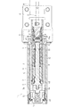
本実施形態に係る操作装置は、図1〜6に示すように、操作用グリップGと、磁石4と、検出センサ6と、節度付与部材8と、操作スイッチとしてのマイクロスイッチ10と、操作手段としての操作ボタン11と、伝達部材12と、係止部材13とを有して構成されており、図11に示すように、船外機Kに取り付けられた操舵ハンドル(D、H)の先端部に配設されている。
Hereinafter, embodiments of the present invention will be specifically described with reference to the drawings.
As shown in FIGS. 1 to 6, the operating device according to the present embodiment includes an operating grip G, a
船外機Kは、同図に示すように、プロペラPを具備した本体K1と、本体K1上に配設された駆動源としてのモータMと、スイベルブラケットB1及びクランプブラケットB2と、操舵ハンドル(D、H)とを具備している。本体K1は、スイベルブラケットB1に対して水平方向に操舵可能に軸支されるとともに、当該スイベルブラケットB1は、クランプブラケットB2にチルト軸L2を介して鉛直方向に傾斜可能に軸支されている。そして、船外機Kは、クランプブラケットB2にて船体Fに取付可能に構成され、モータMの出力をプロペラPに伝達することにより、船体Fを前進、停止、後進可能としている。 As shown in the figure, the outboard motor K includes a main body K1 having a propeller P, a motor M as a drive source disposed on the main body K1, a swivel bracket B1 and a clamp bracket B2, and a steering handle ( D, H). The main body K1 is pivotally supported by the swivel bracket B1 so as to be steerable in the horizontal direction, and the swivel bracket B1 is pivotally supported by the clamp bracket B2 via the tilt shaft L2 so as to be tiltable in the vertical direction. The outboard motor K is configured to be attachable to the hull F by the clamp bracket B2, and by transmitting the output of the motor M to the propeller P, the hull F can be advanced, stopped, and moved backward.
操舵ハンドル(D、H)は、本体K1から船体Fの前方に向かって延設されたもので、当該操舵ハンドル(D、H)を左右方向に揺動させることにより本体K1を同方向(左右方向)に操舵可能とされている。この操舵ハンドルの部位Dと部位Hとの間には、揺動軸L1が設けられており、部位Hの先端部に操作用グリップGが取り付けられるとともに、当該部位Hが部位Dに対して揺動軸L1を中心に上下方向に揺動(同図の状態から上方に跳ね上げ可能)とされている。 The steering handles (D, H) are extended from the main body K1 toward the front of the hull F, and the main body K1 is moved in the same direction (left and right) by swinging the steering handles (D, H) in the left and right directions. Direction). A rocking shaft L1 is provided between the steering wheel part D and the part H, an operation grip G is attached to the tip of the part H, and the part H swings relative to the part D. It swings up and down around the movement axis L1 (can be lifted upward from the state shown in the figure).
操舵ハンドルHの先端には、固定ケースCが固定されており、この固定ケースCを介して当該操舵ハンドルHの先端に金属製の円筒状部材から成るパイプ体Aが連結されているとともに、当該パイプ体A内に固定部材5が固定されている。また、固定ケースCには、操作用グリップGが軸回りに回転可能に取り付けられている。なお、本実施形態においては、パイプ体Aは、操舵ハンドルHの先端に連結された別体の部材とされているが、操舵ハンドルHの先端部であってもよい。
A fixed case C is fixed to the tip of the steering handle H, and a pipe body A made of a metal cylindrical member is connected to the tip of the steering handle H via the fixed case C. A
操作用グリップGは、操舵ハンドルHの先端部に形成され、運転者が把持しつつ中立位置から一方向又は他方向に回転操作可能とされたもので、中立位置から一方向に回転操作されると船舶を前進させ、当該中立位置から他方向に回転操作されると船舶を後進させ得るよう構成されている。 The operation grip G is formed at the front end portion of the steering handle H and can be rotated in one direction or the other direction from the neutral position while being gripped by the driver, and is rotated in one direction from the neutral position. When the ship is moved forward and rotated in the other direction from the neutral position, the ship can be moved backward.
さらに、操作用グリップGの内部には、連動部材2が形成されている。この連動部材2は、操作用グリップGと嵌合して取り付けられており、当該操作用グリップGの回転操作と共に回転し得るとともに、回転部材3の一端3aを係止する係止凹部2aが形成されている。回転部材3は、操作用グリップGの回転軸に沿って延びる軸状の部材から成り、固定部材5内で回転自在とされている。なお、図中符号s2は、連動部材2と回転部材3との間をシールするシール部材を示している。
Further, an interlocking
さらに、回転部材3には、その先端に磁石4が取り付けられているとともに、途中の所定部位にバネ受板7が固定されており、これら磁石4とバネ受板7との間にコイルスプリングS3が介装されている。一方、磁石4は、後述する基板f及び検出センサ6を収容した収容ケース15の外面15aに当接して組み付けられており、コイルスプリングS3の付勢力により当該外面15aに常時押圧された状態とされている。
Furthermore, a
かかる構成により、操作用グリップGを回転操作すると、当該操作用グリップGと共に連動部材2及び回転部材3が回転するとともに、回転部材3と共に磁石4が外面15aに押圧されつつ回転することとなる。すなわち、操作用グリップGを回転操作すると、連動部材2及び回転部材3と共に磁石4も回転し、その対向する部位(収容ケース15内の検出センサ6側)に生じた磁界が回転角度に応じて変化し得るようになっている。尚、かかる磁石4は、永久磁石であっても、他の磁界を生じ得るもの(例えばプラスチック磁石等)であってもよい。
With this configuration, when the operation grip G is rotated, the interlocking
また、回転部材3には、節度付与部材8が取り付けられており、当該回転部材3と共に節度付与部材8も回転するようになっている。この節度付与部材8は、固定部材5内で回転自在に保持されるとともに、バネ受板7との間に介装されたコイルスプリングS2にて常時付勢力が図3、4中左方向に付与されている。また、節度付与部材8は、図9に示すように、その回転中心部に回転部材3を挿通させる挿通孔8bが形成されるとともに、挿通孔8bから外縁に向かって延びる一対の嵌合凹部8aが形成されている。
Further, a
嵌合凹部8aは、溝状に形成された凹部から成り、固定部材5における節度付与部8が押圧される面に形成された嵌合凸部5aと合致して嵌合し得るようになっている。嵌合凸部5aは、操作用グリップGが中立位置にあるとき節度付与部材8の嵌合凹部8aと合致して嵌合し得る位置に形成されている。これにより、操作用グリップGが中立位置から一方向又は他方向に回動操作される際、嵌合凸部5aが嵌合凹部8aを乗り上げて嵌合が外れる過程で節度付与部8がコイルスプリングS2の付勢力に抗して移動し、所定の負荷が生じることで節度が付与されることとなる。
The
なお、本実施形態においては、節度付与部材8に嵌合凹部8aが形成され、固定部材5に嵌合凸部5aが形成されて所定の節度を付与するよう構成されているが、節度付与部材8に嵌合凸部が形成され、固定部材5に嵌合凹部が形成されたものとしてもよい。すなわち、節度付与手段8及び固定部材5の何れか一方の所定部位には、嵌合凹部が形成され、他方には、操作用グリップGが中立位置にあるとき嵌合凹部と合致して嵌合し得る嵌合凸部が形成されたものであればよい。また、嵌合凹部8aの形状及び深さ寸法(それと対応させる嵌合凸部5aも同様)を任意とすることにより、所望の節度を付与することができる。
In the present embodiment, the
このように、節度付与手段8及び固定部材5の何れか一方の所定部位に嵌合凹部を形成し、他方に操作用グリップGが中立位置にあるとき嵌合凹部と合致して嵌合し得る嵌合凸部を形成することにより、操作用グリップGが中立位置から一方向又は他方向に回動操作される際に任意の節度をより確実且つ円滑に付与させることができる。
In this way, a fitting recess is formed in one of the predetermined portions of the
一方、パイプ体A内には、収容ケース15が固定されている。この収容ケース15内は、基板f及び該基板fに形成されたチップ状部材から成る検出センサ6が収容されるとともに、当該基板fからは船外機K側に向かって配線Tが延設されている。また、収容ケース15内には、検出センサ6が形成された基板fを収容した状態にて所定の樹脂を充填して成り、当該基板f及び検出センサ6が樹脂モールドされるよう構成されている。なお、図3、4中符号s3は、収容ケース15とパイプ体Aとの間をシールするシール部材を示している。
On the other hand, a
検出センサ6は、操作用グリップGの回転角度を非接触にて検出し、当該回転角度に応じた検出信号を発生させる角度センサから成り、磁石4から生じる磁界の変化により出力電圧を増減させ得るよう構成されている。なお、基板fには、角度センサから成る検出センサ6の他、該検出センサ6の出力信号を増幅するためのアンプ部やその他の回路が形成されている。
The
さらに、本実施形態に係る検出センサ6は、同一チップ内に角度センサを構成する回路が2つ形成されており、図10に示すように、磁石4から生じる磁界の変化により2つの出力信号(出力1及び出力2)が発生されるようになっている。すなわち、出力1及び出力2は、互いに180度位相がずれた出力信号から成るものとされ、当該出力1と出力2との和を検出信号として送信し得るので、フェールセーフ機能が発揮可能とされている。なお、本実施形態においては、操作用グリップGの回転角度が中立位置から一方向又は他方向に所定角度α回転するまでは出力電圧が変化せず、所定角度α回転した後、それぞれの出力電圧が変動するようになっている。
Furthermore, the
そして、操作用グリップGの回転に伴い磁石4が回転すると、該磁石4から生じる磁界の変化により検出センサ6の出力信号が増減するので、その出力信号に基づいて操作用グリップGの回転角度を検出し得るようになっている。かかる検出信号(電気信号)は、配線Tを介して船外機KにおけるモータMの駆動を制御する駆動制御部に送られ、当該検出信号に基づいた駆動速度の制御(操作用グリップGの回転角度に基づいた出力制御)が行われる。
When the
ここで、本実施形態に係る操作用グリップGの先端側には、当該操作用グリップGを把持しつつ操作可能な操作手段としての操作ボタン11が形成されている。この操作ボタン11は、コイルスプリングS1により常時図3、4中左方向に付勢されたもので、当該コイルスプリングS1の付勢力に抗して押圧操作すると、伝達部材12を介して係止部材13及びマイクロスイッチ10(操作スイッチ)を作動させ得るよう構成されている。なお、図3、4中符号s1は、操作ボタン11と連動部材2との間をシールするシール手段を示している。
Here, on the front end side of the operation grip G according to the present embodiment, an
より具体的に説明すると、伝達部材12は、図3、7に示すように、操作ボタン11(操作手段)からマイクロスイッチ10(操作スイッチ)側まで延設された板状部材から成るとともに、その両端部には、操作ボタン11の所定部位と係止可能な係止孔12a、及び保持部14及び円環状部材9と係止可能な係止孔12bがそれぞれ形成されている。また、伝達部材12は、連動部材2の内周壁面に沿って複数(本実施形態においては、図5に示すように同一円周上において等間隔に3つ)形成されており、操作ボタン11の押圧操作に伴って同押圧操作方向に移動することで、係止部材13を同方向に移動させるとともに、円環状部材9を介してマイクロスイッチ10の作動部10aを押圧させるようになっている。
More specifically, as shown in FIGS. 3 and 7, the
係止部材13は、操作用グリップGが中立位置にあるとき、当該操作用グリップGを係止してその回転を規制するとともに、操作ボタン11にて操作されることにより、操作用グリップGに対する係止が解除されて当該操作用グリップGの一方向又は他方向の回転を許容するものである。すなわち、係止部材13は、図8に示すように、連動部材2の突出部2bに形成された挿通孔2baに挿通されつつコイルスプリングS4にて付勢されて保持部14に取り付けられており、操作用グリップGが中立位置にあるとき、その先端部が固定ケースCに形成された係止孔Caに嵌入されて係止されるようになっている。
When the operating grip G is in the neutral position, the locking
このように、係止部材13の先端部が係止孔Caに嵌入された状態においては、固定ケースCに対して連動部材2が係止されることから、操作用グリップGの回動が規制されることとなる。そして、操作ボタン11の押圧操作に伴って伝達部材12が同押圧操作方向(図8中右方向)に移動することで、係止部材13をコイルスプリングS4の付勢力に抗して同方向に移動させ、当該係止部材13の先端を係止孔Caから離間させることができる。これにより、操作ボタン11を押圧操作することで、中立位置にある操作用グリップGに対する係止が解除されて当該操作用グリップGの一方向又は他方向の回転が許容される。
As described above, in the state where the distal end portion of the locking
マイクロスイッチ10(操作スイッチ)は、作動部10aを有した接触型スイッチから成るもので、操作ボタン11(操作手段)の操作により電気的にオン、オフして船舶(搭乗手段)に搭載された所望の電装品を操作し得るもので、本実施形態においては船外機Kの駆動を強制的に停止させるよう構成されている。すなわち、操作用グリップGが中立位置から一方向又は他方向に回転操作された状態で操作ボタン11を押圧操作すると、伝達部材12及び円環状部材9が同押圧操作方向に移動するので、作動部10aが円環状部材9にて押圧されてマイクロスイッチ10をオンし、船外機Kの駆動(即ち、駆動源であるモータMの駆動)を強制的に停止させる信号(電気信号)を送信し得るのである。
The micro switch 10 (operation switch) is a contact type switch having an operating
このように、本実施形態においては、操作ボタン11(操作手段)は、操作用グリップGの先端部に配設され、マイクロスイッチ10(操作スイッチ)は、当該操作用グリップGの基端側に配設されるとともに、これら操作ボタン11及びマイクロスイッチ10の間には、当該操作ボタン11に対する操作をマイクロスイッチ10に伝達するための板状部材から成る伝達部材12が配設されており、当該伝達部材12に連結された円環状部材9を介してマイクロスイッチ10の作動部10aを押圧可能とされている。
Thus, in the present embodiment, the operation button 11 (operation means) is disposed at the distal end portion of the operation grip G, and the micro switch 10 (operation switch) is disposed on the proximal end side of the operation grip G. Between the
上記のように、本実施形態によれば、操作用グリップGが一方向又は他方向に回転操作された状態で操作すると船外機Kの駆動を強制的に停止させる操作ボタン11(操作手段)が当該操作用グリップGの先端側に配設されたので、緊急停止をより確実かつ円滑に行わせることができ、安全性をより向上させることができる。また、操作用グリップGが中立位置にあるとき、当該操作用グリップGを係止してその回転を規制するとともに、操作ボタン11(操作手段)にて操作されることにより、操作用グリップGに対する係止が解除されて当該操作用グリップGの一方向又は他方向の回転を許容する係止部材13を具備したので、不用意に中立位置からの回動操作が行われてしまうのを回避することができ、より安全性を向上させることができる。
As described above, according to the present embodiment, the operation button 11 (operation means) that forcibly stops the driving of the outboard motor K when the operation grip G is operated in a state of being rotated in one direction or the other direction. Is disposed on the front end side of the operation grip G, the emergency stop can be performed more reliably and smoothly, and the safety can be further improved. Further, when the operation grip G is in the neutral position, the operation grip G is locked to restrict the rotation thereof, and is operated by the operation button 11 (operation means), so that the operation grip G is controlled. Since the locking
特に、本実施形態に係る操作ボタン11(操作手段)においては、操作用グリップGが中立位置にあるとき操作されると、係止部材13による係止を解除させるとともに、当該操作用グリップGが中立位置から一方向又は他方向に回転操作された状態で操作されると、船外機Kの駆動を強制的に停止させるよう構成されている。これにより、それぞれの操作ボタン(係止解除の操作ボタン及び緊急停止の操作ボタン)を配設させるものに比べ、部品点数を削減することができるとともに、構成を簡素化して操作装置の小型化を図ることができる。
In particular, in the operation button 11 (operation means) according to the present embodiment, when the operation grip G is operated when the operation grip G is in the neutral position, the lock by the locking
ここで、本実施形態に係る操作装置1においては、検出センサ6は、操舵ハンドル(H、D)の揺動軸L1より操作用グリップG側(操舵ハンドルHの先端側)に配設されて船外機K側に延びる配線Tが接続されている。これにより、操作ワイヤを介して操作用グリップGの回転操作を伝達させるものに比べ、操作用グリップGの回転角度を精度よく検出することができるとともに、良好かつ円滑に船外機KのモータM(駆動源)を制御することができる。
Here, in the
また、操作用グリップGと共に回転する磁石4が当該操作用グリップG内に配設されるとともに、検出センサ6は、当該磁石4の磁界変化に応じた電気信号を発生して操作用グリップGの回転角度を検出可能とされた角度センサから成るので、操作用グリップGの回転角度をより精度よく且つ安定して検出することができる。さらに、磁石4及び検出センサ6は、操舵ハンドルHを構成するパイプ体又は当該操舵ハンドルHの先端に連結されるパイプ体A内に配設されたので、外部から付与された衝撃から磁石4及び検出センサ6を保護することができ、装置の信頼性を向上させることができる。
In addition, the
またさらに、操作用グリップGが中立位置から一方向に回転操作されると船舶を前進させ、当該中立位置から他方向に回転操作されると船舶を後進させ得るとともに、当該操作用グリップGが中立位置から一方向又は他方向に回動操作される際、節度を付与する節度付与部材8を具備したので、操作感を向上させることができるとともに、船舶の停止、前進、後進のための操作を確実に行わせることができる。
Furthermore, when the operation grip G is rotated in one direction from the neutral position, the ship can be moved forward, and when the operation grip G is rotated in the other direction from the neutral position, the ship can be moved backward, and the operation grip G is neutral. Since the
また、操作ボタン11(操作手段)は、操作用グリップGの先端部に配設され、マイクロスイッチ10(操作スイッチ)は、当該操作用グリップGの基端側に配設されるとともに、これら操作ボタン11及びマイクロスイッチ10の間には、当該操作ボタン11に対する操作をマイクロスイッチ10に伝達するための伝達部材12が配設されたので、検出センサ6等で構成される回転角度検出機構が操作用グリップG内に配設されていても、操作用グリップGの回転角度を確実に検出することができ、かつ、操作ボタン11の操作をマイクロスイッチ10に確実に伝達させることができる。
The operation button 11 (operation means) is disposed at the distal end portion of the operation grip G, and the micro switch 10 (operation switch) is disposed on the proximal end side of the operation grip G, and these operations are performed. Between the
すなわち、操作ボタン11側にマイクロスイッチ10等の操作スイッチを形成した場合、回転角度検出機構の配設部位に、当該操作スイッチからの配線を延設させる必要があることから、検出センサ6の配設箇所や磁石4の形状及び大きさが制限される可能性があるのに対し、本実施形態によれば、任意の伝達部材12にて操作ボタン11の操作をマイクロスイッチ10に確実に伝達させることができ、かつ、検出センサ6の配設箇所や磁石4の形状及び大きさが制限されてしまうのを抑制することができるのである。
That is, when an operation switch such as the
特に、本実施形態によれば、伝達部材12は、操作ボタン11(操作手段)からマイクロスイッチ10(操作スイッチ)側まで延設された板状部材から成るので、より一層、操作ボタン11の操作をマイクロスイッチ10に確実に伝達させることができ、かつ、検出センサ6の配設箇所や磁石4の形状及び大きさが制限されてしまうのを抑制することができる。
In particular, according to the present embodiment, the
また、本実施形態に係る操作手段は、操作用グリップGを把持しつつ押圧操作が可能な操作ボタン11から成るとともに、伝達部材12の先端側に円環状部材9を連結させ、当該円環状部材9を介して操作ボタン11の押圧操作をマイクロスイッチ10(操作スイッチ)に伝達させるよう構成されているので、操作ボタン11及び伝達部材12が操作用グリップGと共に回転する構成であっても、円環状部材9が常にマイクロスイッチ10の作動部10aを押圧可能とすることができ、より確実に操作ボタン11の押圧操作をマイクロスイッチ10に伝達させることができる。
The operation means according to the present embodiment includes an
以上、本実施形態について説明したが、本発明はこれに限定されるものではない。 Having described the present embodiment, the present invention is not name limited thereto.
例えば、上記の如く、操作ボタン11が専ら緊急停止用とされたもの(係止部材を備え、その係止部材による係止を解く機能を有さないもの)としてもよい。また、操作ボタン11に代えて揺動式又はスライド式の操作ノブとしてもよい。またさらに、本実施形態においては、節度付与手段8が配設されているが、他の形態の節度付与手段を具備したもの或いは節度付与手段を具備しないものとしてもよい。
For example, as described above, which
なお、本実施形態においては、配線Tにて電気信号が送信されるものとされているが、光信号等の他の形態の検出信号を送信し得るものとしてもよい。また、本実施形態においては、船外機Kの駆動源がモータMとされているが、エンジン等の他の駆動源を搭載した船外機に適用してもよい。 In the present embodiment, an electrical signal is transmitted through the wiring T. However, another form of detection signal such as an optical signal may be transmitted. In this embodiment, the drive source of the outboard motor K is the motor M, but it may be applied to an outboard motor equipped with another drive source such as an engine.
操舵ハンドルの揺動軸より操作用グリップ側に位置する固定ケース内に配設されて船外機側に延びる配線が接続された検出センサ及び操作スイッチを有した操作装置であれば、外観形状が異なるもの或いは他の機能が付加されたもの等に適用してもよい。 If the operation device has a detection sensor and an operation switch that are arranged in a fixed case located on the operation grip side from the swinging shaft of the steering handle and connected to the outboard motor side, the external shape is You may apply to a different thing or the thing to which the other function was added.
1 操作装置
2 連動部材
3 回転部材
4 磁石
5 固定部材
5a 嵌合凸部
6 検出センサ
7 バネ受板
8 節度付与部材
8a 嵌合凹部
9 円環状部材
10 マイクロスイッチ(操作スイッチ)
11 操作ボタン(操作手段)
12 伝達部材
13 係止部材
14 保持部
15 収容ケース
16 スプリングピン
17 操作ボタン(操作手段)
18 固定接点
A パイプ体
C 固定ケース
T 配線
DESCRIPTION OF
11 Operation buttons (operation means)
12
18 Fixed contact A Pipe body C Fixed case T Wiring
Claims (4)
該操作用グリップの回転角度を非接触にて検出し、当該回転角度に応じた検出信号を発生させる検出センサと、
該検出センサで得られた検出信号を船外機側に送信して当該船外機の駆動速度を制御させる配線と、
前記操作用グリップが軸回りに回転可能に取り付けられた固定ケースと、
前記操作用グリップに形成され、当該操作用グリップを把持しつつ操作可能な操作手段と、
該操作手段の操作により電気的にオン、オフして船舶に搭載された所望の電装品又は船外機を操作し得る操作スイッチと、
を具備した操作装置であって、
前記検出センサ及び操作スイッチは、前記操舵ハンドルの揺動軸より操作用グリップ側に位置する前記固定ケース内に配設されて前記船外機側に延びる配線が接続されたことを特徴とする操作装置。 An operation grip that is swingable in the vertical direction around the swing shaft and is formed at the tip of a steering handle attached to the outboard motor, and that can be rotated while being held by the driver;
A detection sensor that detects a rotation angle of the operation grip in a non-contact manner and generates a detection signal according to the rotation angle;
Wiring for controlling the driving speed of the outboard motor by transmitting the detection signal obtained by the detection sensor to the outboard motor side;
A fixing case in which the grip for operation is rotatably mounted around an axis;
An operating means formed on the operating grip and operable while gripping the operating grip;
An operation switch capable of operating a desired electrical component or outboard motor mounted on a ship by being electrically turned on and off by operation of the operation means;
An operating device comprising:
The operation is characterized in that the detection sensor and the operation switch are arranged in the fixed case located on the operation grip side with respect to the swing shaft of the steering handle and connected to a wiring extending to the outboard motor side. apparatus.
Priority Applications (1)
| Application Number | Priority Date | Filing Date | Title |
|---|---|---|---|
| JP2011289141A JP5886038B2 (en) | 2011-12-28 | 2011-12-28 | Operating device |
Applications Claiming Priority (1)
| Application Number | Priority Date | Filing Date | Title |
|---|---|---|---|
| JP2011289141A JP5886038B2 (en) | 2011-12-28 | 2011-12-28 | Operating device |
Publications (2)
| Publication Number | Publication Date |
|---|---|
| JP2013136347A JP2013136347A (en) | 2013-07-11 |
| JP5886038B2 true JP5886038B2 (en) | 2016-03-16 |
Family
ID=48912478
Family Applications (1)
| Application Number | Title | Priority Date | Filing Date |
|---|---|---|---|
| JP2011289141A Active JP5886038B2 (en) | 2011-12-28 | 2011-12-28 | Operating device |
Country Status (1)
| Country | Link |
|---|---|
| JP (1) | JP5886038B2 (en) |
Families Citing this family (1)
| Publication number | Priority date | Publication date | Assignee | Title |
|---|---|---|---|---|
| CN106347617B (en) * | 2016-10-25 | 2017-12-01 | 常州高尔登科技有限公司 | Electronic Marine paddle hanging device |
Family Cites Families (4)
| Publication number | Priority date | Publication date | Assignee | Title |
|---|---|---|---|---|
| JP5030612B2 (en) * | 2007-02-22 | 2012-09-19 | ヤマハ発動機株式会社 | Ship propulsion machine |
| JP2009073348A (en) * | 2007-09-20 | 2009-04-09 | Suzuki Motor Corp | Handle device of two-wheeler |
| JP2009255770A (en) * | 2008-04-17 | 2009-11-05 | Honda Motor Co Ltd | Outboard motor |
| JP5442323B2 (en) * | 2009-06-05 | 2014-03-12 | 朝日電装株式会社 | Throttle grip device |
-
2011
- 2011-12-28 JP JP2011289141A patent/JP5886038B2/en active Active
Also Published As
| Publication number | Publication date |
|---|---|
| JP2013136347A (en) | 2013-07-11 |
Similar Documents
| Publication | Publication Date | Title |
|---|---|---|
| US8925414B1 (en) | Devices for inputting command signals to marine vessel control systems | |
| JP5030612B2 (en) | Ship propulsion machine | |
| US9896176B2 (en) | Marine propulsion device | |
| WO2014034324A1 (en) | Operating device for electric outboard motor | |
| JP2006131221A (en) | Improved operator control device | |
| JP2002137795A (en) | Remote control device for small ship | |
| JP5103104B2 (en) | Ship propulsion machine | |
| JP5886038B2 (en) | Operating device | |
| JP2005280572A (en) | Steering device for small vessel | |
| JP5249110B2 (en) | Ship propulsion system | |
| JP5875365B2 (en) | Operating device | |
| JP5165902B2 (en) | Vehicle steering system | |
| JP5886039B2 (en) | Operating device | |
| KR20200043829A (en) | Steer-By-Wire Type Steering Apparatus | |
| JP4554230B2 (en) | Steering device | |
| JP4558582B2 (en) | Vehicle operating device | |
| KR20200039273A (en) | Steer by wire type steering apparatus | |
| JP2014054916A (en) | Steering gear | |
| JP5030203B2 (en) | Forklift axle mechanism | |
| JP4376663B2 (en) | Variable transmission ratio steering device | |
| JP4303260B2 (en) | Ship steering device | |
| JP2008100634A (en) | Operating device | |
| JP4186670B2 (en) | Steering device | |
| JP7253166B2 (en) | Throttle operating device | |
| JP2005247010A (en) | Vehicle steering gear |
Legal Events
| Date | Code | Title | Description |
|---|---|---|---|
| A621 | Written request for application examination |
Free format text: JAPANESE INTERMEDIATE CODE: A621 Effective date: 20141105 |
|
| A131 | Notification of reasons for refusal |
Free format text: JAPANESE INTERMEDIATE CODE: A131 Effective date: 20150818 |
|
| A521 | Request for written amendment filed |
Free format text: JAPANESE INTERMEDIATE CODE: A523 Effective date: 20151019 |
|
| TRDD | Decision of grant or rejection written | ||
| A01 | Written decision to grant a patent or to grant a registration (utility model) |
Free format text: JAPANESE INTERMEDIATE CODE: A01 Effective date: 20160205 |
|
| A61 | First payment of annual fees (during grant procedure) |
Free format text: JAPANESE INTERMEDIATE CODE: A61 Effective date: 20160210 |
|
| R150 | Certificate of patent or registration of utility model |
Ref document number: 5886038 Country of ref document: JP Free format text: JAPANESE INTERMEDIATE CODE: R150 |
|
| R250 | Receipt of annual fees |
Free format text: JAPANESE INTERMEDIATE CODE: R250 |
|
| R250 | Receipt of annual fees |
Free format text: JAPANESE INTERMEDIATE CODE: R250 |
|
| R250 | Receipt of annual fees |
Free format text: JAPANESE INTERMEDIATE CODE: R250 |
|
| R250 | Receipt of annual fees |
Free format text: JAPANESE INTERMEDIATE CODE: R250 |
|
| R250 | Receipt of annual fees |
Free format text: JAPANESE INTERMEDIATE CODE: R250 |
|
| R250 | Receipt of annual fees |
Free format text: JAPANESE INTERMEDIATE CODE: R250 |