JP5884591B2 - Image processing apparatus, camera, and image processing program - Google Patents
Image processing apparatus, camera, and image processing program Download PDFInfo
- Publication number
- JP5884591B2 JP5884591B2 JP2012069263A JP2012069263A JP5884591B2 JP 5884591 B2 JP5884591 B2 JP 5884591B2 JP 2012069263 A JP2012069263 A JP 2012069263A JP 2012069263 A JP2012069263 A JP 2012069263A JP 5884591 B2 JP5884591 B2 JP 5884591B2
- Authority
- JP
- Japan
- Prior art keywords
- random number
- number data
- image data
- data
- signal
- Prior art date
- Legal status (The legal status is an assumption and is not a legal conclusion. Google has not performed a legal analysis and makes no representation as to the accuracy of the status listed.)
- Active
Links
Images


Landscapes
- Color Image Communication Systems (AREA)
- Compression Of Band Width Or Redundancy In Fax (AREA)
- Image Processing (AREA)
- Facsimile Image Signal Circuits (AREA)
Description
本発明は、画像処理装置、カメラおよび画像処理プログラムに関する。 The present invention relates to an image processing apparatus, a camera, and an image processing program.
一般的に、撮像素子で取得したアナログ画像信号は、12ビットや14ビットのデジタル画像データにAD変換された後、所定の画像処理が行われる。この画像処理では、少なくとも12ビット以上の画像データで処理が行われる。そして、画像処理後の画像データは、JPEG方式などの共通規格でデータ圧縮されて保存される。JPEG方式により圧縮される場合、画像データは12ビットから8ビットに変換されるため、変換後にトーンジャンプが目立ってしまうことがある。 Generally, an analog image signal acquired by an image sensor is subjected to AD conversion into 12-bit or 14-bit digital image data, and then subjected to predetermined image processing. In this image processing, processing is performed with image data of at least 12 bits. Then, the image data after image processing is stored after being compressed according to a common standard such as the JPEG method. When the image data is compressed by the JPEG method, the image data is converted from 12 bits to 8 bits, and thus the tone jump may be conspicuous after the conversion.
トーンジャンプを解消させる技術としては、画像データに乱数データを加算することで量子化の際のトーンジャンプを解消させる画像処理装置が知られている(特許文献1参照)。 As a technique for eliminating the tone jump, there is known an image processing apparatus that eliminates a tone jump at the time of quantization by adding random number data to image data (see Patent Document 1).
JPEG圧縮ではYCbCr空間を用いるため、JPEG圧縮を行う際には、RGB空間の画像データをYCbCr空間の画像データに変換する。この際、Cb信号およびCr信号(色差信号)の階調数は、変換前におけるR信号およびB信号の階調数の1/2となるため、色差面でのトーンジャンプが一段と目立ちやすい。従来技術では、この点については考慮されていなかった。 Since the YCbCr space is used in JPEG compression, image data in the RGB space is converted into image data in the YCbCr space when JPEG compression is performed. At this time, since the number of gradations of the Cb signal and the Cr signal (color difference signal) is ½ of the number of gradations of the R signal and the B signal before conversion, the tone jump on the color difference surface is more conspicuous. The prior art did not consider this point.
(1)請求項1に記載の発明による画像処理装置は、YCbCr色空間の画像データに対して、乱数データを付加する乱数データ付加手段と、乱数データを付加したYCbCr色空間の画像データを、当該画像データよりもビット深度の少ないYCbCr色空間の画像データへビット変換するビット変換手段と、を備え、乱数データ付加手段は、YCbCr色空間の画像データにおけるY信号、Cb信号、およびCr信号のそれぞれに乱数データを付加し、Cb信号およびCr信号に付加する乱数データは、Y信号に付加する乱数データよりも取り得る値の幅が大きいことを特徴とする。
(2)請求項2に記載の発明による画像処理装置は、YCbCr色空間の画像データに対して、乱数データを付加する乱数データ付加手段と、乱数データを付加したYCbCr色空間の画像データを、当該画像データよりもビット深度の少ないYCbCr色空間の画像データへビット変換するビット変換手段と、を備え、乱数データ付加手段は、YCbCr色空間の画像データにおけるCb信号およびCr信号のみにそれぞれ乱数データを付加することを特徴とする。
(3)請求項8に記載の発明によるカメラは、請求項1〜7のいずれか一項に記載の画像処理装置を備えることを特徴とする。
(4)請求項9に記載の発明による画像処理プログラムは、コンピュータに、YCbCr色空間の画像データに対して、乱数データを付加する乱数データ付加工程と、乱数データを付加したYCbCr色空間の画像データを、当該画像データよりもビット深度の少ないYCbCr色空間の画像データへビット変換するビット変換工程と、を実行させるための画像処理プログラムであって、乱数データ付加工程では、YCbCr色空間の画像データにおけるY信号、Cb信号、およびCr信号のそれぞれに乱数データを付加し、Cb信号およびCr信号に付加する乱数データは、Y信号に付加する乱数データよりも取り得る値の幅が大きいことを特徴とする。
(5)請求項10に記載の発明による画像処理プログラムは、コンピュータに、YCbCr色空間の画像データに対して、乱数データを付加する乱数データ付加工程と、乱数データを付加したYCbCr色空間の画像データを、当該画像データよりもビット深度の少ないYCbCr色空間の画像データへビット変換するビット変換工程と、を実行させるための画像処理プログラムであって、乱数データ付加工程では、YCbCr色空間の画像データにおけるCb信号およびCr信号のみにそれぞれ乱数データを付加することを特徴とする。
(1) An image processing apparatus according to the first aspect of the present invention includes: random number data adding means for adding random number data to image data in the YCbCr color space; and image data in the YCbCr color space to which random number data is added. Bit conversion means for bit-converting into image data in a YCbCr color space having a bit depth smaller than that of the image data, and the random number data adding means includes a Y signal, a Cb signal, and a Cr signal in the image data in the YCbCr color space. Random number data added to each of the random number data added to the Cb signal and the Cr signal has a larger range of possible values than the random number data added to the Y signal.
(2) The image processing apparatus according to the invention described in
(3) A camera according to an eighth aspect of the invention includes the image processing device according to any one of the first to seventh aspects.
(4) An image processing program according to the invention described in
(5) An image processing program according to the invention described in claim 10 includes a random number data adding step for adding random number data to image data in the YCbCr color space, and an image in the YCbCr color space to which the random number data is added. A bit conversion process for performing bit conversion of data into image data in a YCbCr color space having a bit depth smaller than that of the image data. In the random number data addition process, an image in the YCbCr color space Random number data is added to only the Cb signal and Cr signal in the data, respectively.
本発明によれば、色差信号におけるトーンジャンプを目立たなくすることができる。 According to the present invention, the tone jump in the color difference signal can be made inconspicuous.
以下、図面を参照して本発明を実施するための形態について説明する。図1は、本実施の形態における画像処理装置を搭載したデジタルカメラの一実施の形態の構成を示すブロック図である。デジタルカメラ100は、操作部材101と、撮像レンズ102と、撮像素子103と、制御装置104と、メモリカードスロット105と、モニタ106とを備えている。操作部材101は、ユーザによって操作される種々の入力部材、例えば電源スイッチ、レリーズボタン、マルチセレクタ、再生ボタン、削除ボタンなどを含んでいる。
Hereinafter, embodiments for carrying out the present invention will be described with reference to the drawings. FIG. 1 is a block diagram showing a configuration of an embodiment of a digital camera equipped with an image processing apparatus according to the present embodiment. The
撮像レンズ102は、被写体像を撮像素子103の撮像面に結像するように配置されている。撮像レンズ102は、図1では代表して1枚のレンズで表しているが、実際は複数の光学レンズから構成される。
The
撮像素子103は、例えばCMOSなどのイメージセンサであり、撮像レンズ102により結像した被写体像を撮像して、撮像によって得られた画像信号を制御装置104へ出力する。撮像素子103の受光面には、周知のカラーフィルターが設けられている。カラーフィルターは、赤(R)色、青(B)色、および緑(G)色のいずれかの光を通過させる原色フィルタが画素位置に対応してベイヤー配列で構成された色分解フィルタである。撮像素子103は、このようなカラーフィルターを通して被写体像を撮像することにより、光の3原色ごとのカラー画像信号を出力する。
The
撮像素子103で生成された画像信号は、不図示のA/D変換部でデジタル信号に変換され、RAWデータとして制御装置104に出力される。RAWデータとは、入射光の光量と出力信号値との関係が線形の関係となるデジタル画像であり、ベイヤー補間、ホワイトバランス変換、γ変換などが施されていない画像データである。
An image signal generated by the
制御装置104は、CPU、メモリ、およびその他の周辺回路により構成され、デジタルカメラ100全体の制御を行う。なお、制御装置104を構成するメモリには、SDRAMやフラッシュメモリが含まれる。SDRAMは、揮発性のメモリであって、CPUがプログラム実行時にプログラムを展開するためのワークメモリとして使用されたり、データを一時的に記録するためのバッファメモリとして使用されたりする。また、フラッシュメモリは、不揮発性のメモリであって、制御装置104が実行するプログラムのデータや、プログラム実行時に読み込まれる種々のパラメータなどが記録されている。
The
メモリカードスロット105は、記憶媒体としてのメモリカードを挿入するためのスロットである。モニタ106は、デジタルカメラ100の背面に搭載された液晶モニタ(背面モニタ)である。
The
制御装置104は、操作部材101のレリーズボタンが全押し操作されると、撮像素子103から入力されたRAWデータに対して後述する画像処理を施す。そして制御装置104は、上記画像処理後の画像データを、JPEG形式に圧縮してJPEG画像データを生成する。制御装置104は、生成したJPEG画像データをメモリカードスロット105に挿入されたメモリカードに書き込んで記録する。また、制御装置104は、操作部材101の再生ボタンが操作されると、メモリカードスロット105に挿入されているメモリカードに記録された画像を再生してモニタ106に表示させる。
When the release button of the
ところで、JPEG圧縮ではYCbCr空間を用いるため、JPEG圧縮を行う際には、RGB空間の画像データをYCbCr空間の画像データに変換する。具体的に、JPEG圧縮規格で採用されている、RGB空間からYCbCr空間への変換式を、次式(1)〜(3)に示す。
Y = Kr * R + Kg * G + Kb * B …(1)
Cb = {1/2 * (B-Y) / (1-Kb) }+ 128 …(2)
Cr = {1/2 * (R-Y) / (1-Kr) }+ 128 …(3)
By the way, since the YCbCr space is used in JPEG compression, when JPEG compression is performed, image data in the RGB space is converted into image data in the YCbCr space. Specifically, the conversion formulas from RGB space to YCbCr space, which are adopted in the JPEG compression standard, are shown in the following formulas (1) to (3).
Y = Kr * R + Kg * G + Kb * B (1)
Cb = {1/2 * (BY) / (1-Kb)} +128 (2)
Cr = {1/2 * (RY) / (1-Kr)} +128 (3)
式(1)〜(3)において、例えば、Kr=0.299、Kg=0.587、Kb=0.114である。また、画像データが8ビットの場合、R信号の取り得る値の範囲は、0〜255である。ここで、式(1)〜(3)にR=0、G=0、B=0を代入すると、Cr=128となる。また、式(1)〜(3)にR=255、G=0、B=0を代入すると、Cr=255となる。すなわち、変換前のR信号では0〜255の256階調であったのが、変換後のCr信号では128〜255の128階調となり、階調数が1/2となる。なお、Cb信号でも同様に階調数が1/2となる。 In the formulas (1) to (3), for example, Kr = 0.299, Kg = 0.487, and Kb = 0.114. When the image data is 8 bits, the range of values that the R signal can take is 0 to 255. Here, if R = 0, G = 0, and B = 0 are substituted into the equations (1) to (3), Cr = 128. Further, if R = 255, G = 0, and B = 0 are substituted into formulas (1) to (3), Cr = 255. That is, the R signal before conversion has 256 gradations of 0 to 255, but the converted Cr signal has 128 gradations of 128 to 255, and the number of gradations is halved. Note that the number of gradations is also halved in the Cb signal.
このように、JPEG圧縮の際にRGB空間の画像データをYCbCr空間の画像データに変換すると、Cr信号およびCb信号の階調数は、変換前におけるR信号およびB信号の階調数の1/2となる。したがって、輝度面(Y)でのトーンジャンプと比較して、色差面(CbCr)でのトーンジャンプがより目立ってしまう。また、トーンジャンプは、JPEGでの圧縮量が大きくなると、さらに目立ってしまう。 As described above, when image data in the RGB space is converted into image data in the YCbCr space during JPEG compression, the number of gradations of the Cr and Cb signals is 1 / number of gradations of the R and B signals before conversion. 2. Therefore, the tone jump on the color difference plane (CbCr) becomes more conspicuous than the tone jump on the luminance plane (Y). Also, the tone jump becomes more noticeable when the amount of compression in JPEG increases.
このような問題を解決するため、本実施の形態において制御装置104は、図2に例示する処理を実行する。制御装置104は、ユーザにより操作部材101のレリーズボタンが押下されると、図2に例示する処理を実行するプログラムを起動する。
In order to solve such a problem, in the present embodiment, the
ステップS1において、制御装置104は、所定の撮影処理を行って撮像素子103からRAWデータを取得し、ステップS2に進む。なお、このRAWデータは、12ビット深度を有しているとする。
In step S1, the
ステップS2において、制御装置104は、上記12ビットのRAWデータに対して公知のベイヤー補間処理を行って、ステップS3に進む。
In step S2, the
ステップS3において、制御装置104は、次式(4)〜(6)により、上記ベイヤー補間処理後の12ビットの画像データに対して公知の階調変換処理を行って、ニー補正、sRGB規格のガンマ補正、黒締め、コントラスト調整などを行い、ステップS4に進む。
In step S3, the
R’[x,y]=ganma(R[x,y]) …(4)
G’[x,y]=ganma(G[x,y]) …(5)
B’[x,y]=ganma(B[x,y]) …(6)
R '[x, y] = ganma (R [x, y]) (4)
G '[x, y] = ganma (G [x, y]) (5)
B '[x, y] = ganma (B [x, y]) (6)
なお、式(4)〜(6)において、[x,y]は、画素の座標であり、R[x,y]、G[x,y]、B[x,y]は、各画素における上記ベイヤー補間処理後のRGB値である。また、R’[x,y]、G’[x,y]、B’[x,y]は、階調変換処理後のRGB値である。さらに、ganma()は、階調変換を行う関数である。 In Expressions (4) to (6), [x, y] is the pixel coordinates, and R [x, y], G [x, y], and B [x, y] It is an RGB value after the Bayer interpolation process. R ′ [x, y], G ′ [x, y], and B ′ [x, y] are RGB values after gradation conversion processing. Furthermore, ganma () is a function that performs gradation conversion.
ステップS4において、制御装置104は、次式(7)〜(9)により、上記階調変換処理後の12ビットの画像データに対して、所定の3×3のマトリックスを用いて、RGB空間からYCbCr空間への色空間変換を行い、ステップS5に進む。ここで、彩度や色相を整える。
In step S4, the
Y[x,y] = Mycc[1,1] * R’[x,y] + Mycc[1,2] * G’[x,y] + Mycc[1,3] * B’[x,y] …(7)
Cr[x,y] = Mycc[2,1] * R’[x,y] + Mycc[2,2] * G’[x,y] + Mycc[2,3] * B’[x,y] …(8)
Cb[x,y] = Mycc[3,1] * R’[x,y] + Mycc[3,2] * G’[x,y] + Mycc[3,3] * B’[x,y] …(9)
Y [x, y] = Mycc [1,1] * R '[x, y] + Mycc [1,2] * G' [x, y] + Mycc [1,3] * B '[x, y ] (7)
Cr [x, y] = Mycc [2,1] * R '[x, y] + Mycc [2,2] * G' [x, y] + Mycc [2,3] * B '[x, y ] (8)
Cb [x, y] = Mycc [3,1] * R '[x, y] + Mycc [3,2] * G' [x, y] + Mycc [3,3] * B '[x, y ] (9)
なお、式(7)〜(9)において、Y[x,y]、Cb[x,y]、Cr[x,y]は、色空間変換後のYCrCb値である。また、Mycc[a,b](a,bは1〜3)は、上記マトリックスのパラメータである。 In equations (7) to (9), Y [x, y], Cb [x, y], and Cr [x, y] are YCrCb values after color space conversion. Mycc [a, b] (a and b are 1 to 3) is a parameter of the matrix.
ステップS5において、制御装置104は、不図示の疑似乱数データ発生器で線形帰還シフトレジスタなどを用いて疑似乱数データを発生させ、ステップS6に進む。なお、この疑似乱数データは、−1から1までの値をとるものとする。
In step S5, the
ステップS6において、制御装置104は、次式(10)〜(12)により、ステップS4でYCbCr空間に変換した12ビットの画像データに対し、ステップS5で発生させた疑似乱数データを付加して、ステップS7に進む。
In step S6, the
Y’[x,y] = Y[x,y] + rand() * rndY …(10)
Cb’[x,y] = Cb[x,y] + rand() * rndCb …(11)
Cr’[x,y] = Cr[x,y] + rand() * rndCr …(12)
Y '[x, y] = Y [x, y] + rand () * rndY (10)
Cb '[x, y] = Cb [x, y] + rand () * rndCb (11)
Cr '[x, y] = Cr [x, y] + rand () * rndCr (12)
なお、式(10)〜(12)において、Y’[x,y]、Cb’[x,y]、Cr’[x,y]は、疑似乱数データ付加後のYCrCb値である。また、rand()は、ステップS5で発生させた疑似乱数データである。さらに、rndY、rndCb、rndCrは、Y信号、Cb信号、Cr信号にそれぞれ付加する疑似乱数データの値の幅を決定する係数であり、rndCbおよびrndCrは、rndYよりも2〜4倍大きい値である。すなわち、CbCr信号には、Y信号に付加する疑似乱数データよりも2〜4倍程度の大きさの値を取り得る疑似乱数データを付加する。これにより、Y信号のトーンジャンプと比較してCbCr信号のトーンジャンプが目立つのを防ぐことができる。 In equations (10) to (12), Y ′ [x, y], Cb ′ [x, y], and Cr ′ [x, y] are YCrCb values after addition of pseudo-random number data. Also, rand () is pseudo random number data generated in step S5. Further, rndY, rndCb, and rndCr are coefficients that determine the width of the value of the pseudo random number data added to the Y signal, Cb signal, and Cr signal, respectively, and rndCb and rndCr are 2 to 4 times larger than rndY is there. That is, pseudo random number data that can take a value about 2 to 4 times larger than the pseudo random number data added to the Y signal is added to the CbCr signal. Thereby, it is possible to prevent the tone jump of the CbCr signal from being noticeable as compared with the tone jump of the Y signal.
ステップS7において、制御装置104は、次式(13)〜(15)により、上記疑似乱数データを付加した12ビットの画像データを、8ビットの画像データへビット変換し、ステップS8に進む。ここでは、上位8ビットを取り出すようにビット変換を行う。なお、次式(13)〜(15)において、Y”[x,y]、Cb”[x,y]、Cr”[x,y]は、ビット変換後のYCrCb値である。
Y”[x,y] = Y’[x,y]/16 …(13)
Cb”[x,y] = Cb’[x,y]/16 …(14)
Cr”[x,y] = Cr’[x,y]/16 …(15)
In step S7, the
Y "[x, y] = Y '[x, y] / 16 (13)
Cb "[x, y] = Cb '[x, y] / 16 (14)
Cr ”[x, y] = Cr '[x, y] / 16 (15)
このとき下位4ビットの情報は失われるが、あらかじめ乱数が付加されているため、そのデータがある段階の大きさとなるか、次の段階の大きさになるかは確率分布となり、周辺の複数画素の平均値では8ビット以上の表現が可能になり、トーンジャンプの発生を防止することが可能になる。 At this time, the information of the lower 4 bits is lost, but since a random number is added in advance, it becomes a probability distribution whether the data has a certain size or the next size, and a plurality of surrounding pixels The average value of 8 can express 8 bits or more, and it is possible to prevent the occurrence of tone jump.
ステップS8において、制御装置104は、ステップS7で8ビットに変換したYCbCr画像データに対して公知のJPEG圧縮処理を施してJPEG画像データに変換し、ステップS9に進む。
In step S8, the
ステップS9において、制御装置104は、ステップS8で変換したJPEG画像データをメモリカードスロット105に挿入されたメモリカードに書き込んで保存し、図2の処理を終了する。
In step S9, the
以上説明した実施の形態によれば、次の作用効果が得られる。
(1)デジタルカメラ100は、YCbCr色空間の画像データに対して、乱数データ(疑似乱数データ)を付加する制御装置104と、乱数データを付加したYCbCr色空間の画像データを、当該画像データよりもビット深度の少ないYCbCr色空間の画像データへビット変換する制御装置104と、を備え、制御装置104は、YCbCr色空間の画像データにおけるY信号、Cb信号、およびCr信号のそれぞれに乱数データを付加し、Cb信号およびCr信号に付加する乱数データは、Y信号に付加する乱数データよりも取り得る値の幅が大きいように構成したので、ざらつきをそれほど増加させずにビット変換後の画像データのトーンジャンプを目立たなくすることができる。また本実施形態では、ビット変換前の画像データ(12ビットの画像データ)に対して乱数データを付加するようにしたので、ビット変換後の画像データ(8ビットの画像データ)に対して乱数データを付加する場合と比較して、適切にトーンジャンプを低減することができる。
According to the embodiment described above, the following operational effects can be obtained.
(1) The
(2)上記(1)のデジタルカメラ100において、上記ビット変換した画像データに対してJPEG圧縮処理を行う制御装置104をさらに備えるように構成したので、JPEG圧縮処理後の画像データにおいても、トーンジャンプを目立たなくすることができる。
(2) Since the
(変形例1)
上述したようにYCbCr画像データに疑似乱数データを付加した場合、JPEG圧縮前の情報量が増加することになるので、JPEG圧縮を行っても期待するほど圧縮されない場合もある。そこで、JPEG圧縮において、圧縮量を優先する圧縮量優先モードで圧縮するか、トーンジャンプの低減を優先するトーンジャンプ低減優先モードで圧縮するかを、ユーザが操作部材101を操作することで選択できるようにしてもよい。
(Modification 1)
As described above, when pseudo random number data is added to YCbCr image data, the amount of information before JPEG compression increases, so even if JPEG compression is performed, it may not be compressed as expected. Therefore, in JPEG compression, the user can select whether the compression is performed in the compression amount priority mode that prioritizes the compression amount or the tone jump reduction priority mode that prioritizes reduction of the tone jump by operating the
変形例1の制御装置104は、操作部材101からの操作信号に応じて圧縮量優先モードを選択した場合、12ビットのYCbCr画像データに疑似乱数データを付加せずに8ビットへ変換し、変換後の画像データに対してJPEG圧縮を行う。この圧縮量優先モードによれば、トーンジャンプが低減されないものの圧縮量を大きくすることができる。
When the compression amount priority mode is selected according to the operation signal from the
一方、制御装置104は、操作部材101からの操作信号に応じてトーンジャンプ低減優先モードを選択した場合、上述した実施の形態のように12ビットのYCbCr画像データに疑似乱数データを付加した後8ビットへ変換し、変換後の画像データに対してJPEG圧縮を行う。このトーンジャンプ低減優先モードによれば、圧縮量が圧縮量優先モードの場合よりも小さくなるもののトーンジャンプを低減することができる。
On the other hand, when the
(変形例2)
YCbCr色空間の画像データに付加する疑似乱数データの取り得る値の幅を、JPEG圧縮処理の圧縮量に応じて設定するようにしてもよい。この場合の制御装置104は、JPEG圧縮処理の圧縮量が大きいほど、上述したrndY、rndCb、rndCrの値を大きく設定して、YCbCr信号に付加する疑似乱数データの取り得る値の幅を大きくする。これにより、圧縮量が大きくなっても、トーンジャンプが目立つのを防ぐことができる。
(Modification 2)
The range of values that can be taken by the pseudo-random number data added to the image data in the YCbCr color space may be set according to the compression amount of the JPEG compression process. In this case, the
同様に、YCbCr信号に付加する疑似乱数データの取り得る値の幅を、JPEG圧縮処理の圧縮パラメータに応じて設定するようにしてもよい。JPEG圧縮処理の圧縮パラメータとしては、例えば、量子化係数や、サンプリング比(色差成分の間引き量を示す値)などがある。この場合の制御装置104は、圧縮量が大きくなる圧縮パラメータの設定であるほど、YCbCr信号に付加する疑似乱数データの取り得る値の幅を大きくする。
Similarly, the range of values that can be taken by the pseudo random number data added to the YCbCr signal may be set according to the compression parameter of the JPEG compression process. As compression parameters for JPEG compression processing, for example, there are a quantization coefficient, a sampling ratio (a value indicating a thinning amount of a color difference component), and the like. In this case, the
(変形例3)
YCbCr色空間の画像データに付加する疑似乱数データの取り得る値の幅を、画像の乱雑度に応じて設定するようにしてもよい。この場合の制御装置104は、ステップS4で変換された12ビットのYCbCr画像データに対して、画像の乱雑度を解析する解析処理を実行する。この解析処理では、例えば、画像のエントロピーを算出して画像の乱雑度を求めればよい。そして制御装置104は、画像の乱雑度が低いほど、上述したrndY、rndCb、rndCrの値を大きく設定して、YCbCr信号に付加する疑似乱数データの取り得る値の幅を大きくする。一般的に、乱雑度が高い画像ではトーンジャンプが発生しにくいが、乱雑度が低い画像(すなわち整然とした画像、例えば空を撮影したグラデーションの画像など)ではトーンジャンプが発生しやすい。ゆえに、この変形例3によれば、乱雑度が低い画像の場合は、YCbCr信号に付加する疑似乱数データの取り得る値を大きくすることで、適切にトーンジャンプを抑制できる。また、乱雑度が高い画像の場合は、YCbCr信号に付加する疑似乱数データの取り得る値を小さくすることで、疑似乱数データの付加による情報量の増加を抑制することができる。
(Modification 3)
You may make it set the width | variety of the value which the pseudorandom number data added to the image data of YCbCr color space can take according to the randomness of an image. In this case, the
(変形例4)
上述した実施の形態では、YCbCr色空間の画像データに付加する疑似乱数データの取り得る値の幅を、画像全体で同一とする例について説明した。しかしながら、制御装置104は、YCbCr色空間の画像データの部分ごとに、当該画像データに付加する疑似乱数データの取り得る値の幅を変えるようにしてもよい。
(Modification 4)
In the above-described embodiment, the example in which the width of the value that can be taken by the pseudo random number data added to the image data in the YCbCr color space is the same in the entire image has been described. However, the
この場合の制御装置104は、ステップS4で変換された12ビットのYCbCr画像データに対して、例えば、被写体を認識する被写体認識処理を実行する。なお、この被写体認識処理については、公知の方法を用いればよい。制御装置104は、被写体認識処理の結果、画像内で、トーンジャンプが発生しやすい被写体(例えば空や壁など)の部分に対しては、上述したrndY、rndCb、rndCrの値を大きく設定して、YCbCr信号に付加する疑似乱数データの取り得る値の幅を大きくする。一方、トーンジャンプが発生しにくい被写体(例えば人など)の部分に対しては、上述したrndY、rndCb、rndCrの値を小さく設定して、YCbCr信号に付加する疑似乱数データの取り得る値の幅を小さくする。変形例4によれば、トーンジャンプを適切に抑制することができるとともに、疑似乱数データの付加による情報量の増加も抑制することができる。
In this case, the
(変形例5)
YCbCr信号に付加する疑似乱数データの取り得る値の幅を、ユーザが変更できるようにしてもよい。この場合、例えば、JPEG圧縮後の画像をモニタ106に表示させてユーザに目視確認させながら、操作部材101の操作によってYCbCr信号に付加する疑似乱数データの取り得る値の幅を変更できるようにする。こうすることにより、ユーザは、自身が許容できるトーンジャンプの度合いに応じて、YCbCr信号に付加する疑似乱数データの取り得る値の幅を選択することができる。
(Modification 5)
The user may be able to change the range of values that can be taken by the pseudo-random number data added to the YCbCr signal. In this case, for example, while the JPEG-compressed image is displayed on the
(変形例6)
上述した実施の形態では、ビット変換前のY信号、Cb信号およびCr信号に対して、それぞれ疑似乱数データを付加する例について説明した。しかしながら、制御装置104は、Y信号には疑似乱数データを付加せず、Cb信号およびCr信号のみに、それぞれ疑似乱数データを付加するようにしてもよい。変形例6によっても、上述した実施の形態と同様に、トーンジャンプが目立ちやすい色差面(CbCr)においてトーンジャンプを抑制できるので、JPEG圧縮後の画像においてトーンジャンプを目立ちにくくすることができる。
(Modification 6)
In the above-described embodiment, the example in which the pseudo random number data is added to the Y signal, the Cb signal, and the Cr signal before bit conversion has been described. However, the
(変形例7)
上述した実施の形態では、ビット変換前のYCbCr色空間の画像データに対して疑似乱数データを付加する例について説明したが、再現不可能な真の乱数データを付加するようにしてもよい。この場合の制御装置104は、例えばダイオードの生成するノイズや熱雑音などの物理現象を用いて真の乱数データを生成するハードウェア乱数発生器から入力される真の乱数データを、ビット変換前のYCbCr色空間の画像データに付加する。
(Modification 7)
In the embodiment described above, an example in which pseudo-random number data is added to image data in the YCbCr color space before bit conversion has been described, but true random data that cannot be reproduced may be added. In this case, the
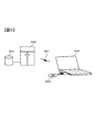
(変形例8)
上述した実施形態では、デジタルカメラ100の制御装置104が図2に示す処理を行う例を説明したが、図2に示す処理を行う画像処理プログラムを図3に示すコンピュータ200に実行させることにより、図2に示す処理を行う画像処理装置を構成するようにしてもよい。図2に示す処理を行う画像処理プログラムをコンピュータ200に取込んで使用する場合には、コンピュータ200のデータストレージ装置に当該画像処理プログラムをローディングした上で、当該画像処理プログラムを実行させる。
(Modification 8)
In the above-described embodiment, the example in which the
コンピュータ200に対する上記画像処理プログラムのローディングは、上記画像処理プログラムを格納したCD−ROMなどの記憶媒体204をコンピュータ200にセットして行ってもよいし、ネットワークなどの通信回線201を経由する方法でコンピュータ200へローディングしてもよい。通信回線201を経由する場合は、通信回線201に接続されたサーバー(コンピュータ)202のストレージ装置203などに上記画像処理プログラムを格納しておく。上記画像処理プログラムは、記憶媒体や通信回線を介する提供など、種々の形態のコンピュータプログラム製品として供給することができる。
The loading of the image processing program to the
なお、コンピュータ200で画像処理装置を構成する場合は、図2のステップS1に代えて、RAWデータが記録された記録媒体(メモリカードなど)から、当該RAWデータを読みだし、ステップS2以降の処理を行う。
When the image processing apparatus is configured by the
以上の説明はあくまで一例であり、上記の実施形態の構成に何ら限定されるものではない。また、上記実施形態に各変形例の構成を適宜組み合わせてもかまわない。 The above description is merely an example, and is not limited to the configuration of the above embodiment. Moreover, you may combine the structure of each modification suitably with the said embodiment.
100…デジタルカメラ、101…操作部材、102…撮像レンズ、103…撮像素子、104…制御装置、105…メモリカードスロット、106…モニタ、200…コンピュータ、201…通信回線、202…サーバー、203…ストレージ装置、204…記憶媒体
DESCRIPTION OF
Claims (10)
前記乱数データを付加したYCbCr色空間の画像データを、当該画像データよりもビット深度の少ないYCbCr色空間の画像データへビット変換するビット変換手段と、
を備え、
前記乱数データ付加手段は、前記YCbCr色空間の画像データにおけるY信号、Cb信号、およびCr信号のそれぞれに乱数データを付加し、Cb信号およびCr信号に付加する乱数データは、Y信号に付加する乱数データよりも取り得る値の幅が大きいことを特徴とする画像処理装置。 Random number data adding means for adding random number data to the image data in the YCbCr color space;
Bit conversion means for bit-converting the image data in the YCbCr color space to which the random number data is added to image data in the YCbCr color space having a bit depth smaller than that of the image data;
With
The random number data adding means adds random number data to each of the Y signal, Cb signal, and Cr signal in the image data in the YCbCr color space, and adds random number data to be added to the Cb signal and Cr signal to the Y signal. An image processing apparatus characterized in that a range of possible values is larger than that of random number data.
前記乱数データを付加したYCbCr色空間の画像データを、当該画像データよりもビット深度の少ないYCbCr色空間の画像データへビット変換するビット変換手段と、
を備え、
前記乱数データ付加手段は、前記YCbCr色空間の画像データにおけるCb信号およびCr信号のみにそれぞれ乱数データを付加することを特徴とする画像処理装置。 Random number data adding means for adding random number data to the image data in the YCbCr color space;
Bit conversion means for bit-converting the image data in the YCbCr color space to which the random number data is added to image data in the YCbCr color space having a bit depth smaller than that of the image data;
With
The random number data adding means adds the random number data only to the Cb signal and the Cr signal in the image data in the YCbCr color space, respectively.
前記ビット変換手段によりビット変換された画像データに対してJPEG圧縮処理を行うJPEG圧縮手段をさらに備えることを特徴とする画像処理装置。 The image processing apparatus according to claim 1 or 2,
An image processing apparatus, further comprising: JPEG compression means for performing JPEG compression processing on the image data bit-converted by the bit conversion means.
前記乱数データ付加手段は、前記JPEG圧縮手段による圧縮量が大きいほど、前記乱数データの取り得る値の幅を大きくすることを特徴とする画像処理装置。 The image processing apparatus according to claim 3.
The random number data adding means increases the range of values that the random number data can take as the amount of compression by the JPEG compression means increases.
前記YCbCr色空間の画像データの乱雑度を解析する解析手段をさらに備え、
前記乱数データ付加手段は、前記解析手段により解析された前記乱雑度が低いほど、前記乱数データの取り得る値の幅を大きくすることを特徴とする画像処理装置。 In the image processing device according to any one of claims 1 to 4,
An analysis means for analyzing the randomness of the image data in the YCbCr color space;
The random number data adding means increases the range of values that the random number data can take as the randomness analyzed by the analyzing means is lower.
前記乱数データ付加手段は、前記YCbCr色空間の画像データの部分ごとに、前記乱数データの取り得る値の幅を設定することを特徴とする画像処理装置。 In the image processing device according to any one of claims 1 to 5,
The image processing apparatus according to claim 1, wherein the random number data adding means sets a range of values that the random number data can take for each portion of the image data in the YCbCr color space.
操作部材と、
前記操作部材からの操作信号に応じて第1の圧縮モードまたは第2の圧縮モードのいずれかを選択する選択手段をさらに備え、
前記選択手段により前記第1の圧縮モードが選択された場合には、前記乱数データ付加手段は、前記YCbCr色空間の画像データに前記乱数データを付加せず、前記ビット変換手段は、前記乱数データを付加していない前記YCbCr色空間の画像データに対して前記ビット変換を行い、前記JPEG圧縮手段が当該ビット変換後の画像データに対してJPEG圧縮処理を行い、
前記選択手段により前記第2の圧縮モードが選択された場合には、前記乱数データ付加手段は、前記YCbCr色空間の画像データに前記乱数データを付加し、前記ビット変換手段は、前記乱数データを付加した前記YCbCr色空間の画像データに対して前記ビット変換を行い、前記JPEG圧縮手段が当該ビット変換後の画像データに対してJPEG圧縮処理を行うことを特徴とする画像処理装置。 The image processing apparatus according to claim 3.
An operation member;
Selecting means for selecting either the first compression mode or the second compression mode according to an operation signal from the operation member;
When the first compression mode is selected by the selection unit, the random number data addition unit does not add the random number data to the image data in the YCbCr color space, and the bit conversion unit The bit conversion is performed on the image data in the YCbCr color space to which no image is added, and the JPEG compression means performs JPEG compression processing on the image data after the bit conversion,
When the second compression mode is selected by the selection unit, the random number data addition unit adds the random number data to the image data in the YCbCr color space, and the bit conversion unit converts the random number data An image processing apparatus, wherein the bit conversion is performed on the added image data in the YCbCr color space, and the JPEG compression unit performs JPEG compression processing on the image data after the bit conversion.
YCbCr色空間の画像データに対して、乱数データを付加する乱数データ付加工程と、
前記乱数データを付加したYCbCr色空間の画像データを、当該画像データよりもビット深度の少ないYCbCr色空間の画像データへビット変換するビット変換工程と、
を実行させるための画像処理プログラムであって、
前記乱数データ付加工程では、前記YCbCr色空間の画像データにおけるY信号、Cb信号、およびCr信号のそれぞれに乱数データを付加し、Cb信号およびCr信号に付加する乱数データは、Y信号に付加する乱数データよりも取り得る値の幅が大きいことを特徴とする画像処理プログラム。 On the computer,
A random number data adding step for adding random number data to the image data in the YCbCr color space;
A bit conversion step of bit-converting the image data in the YCbCr color space to which the random number data is added to image data in the YCbCr color space having a bit depth smaller than that of the image data;
An image processing program for executing
In the random number data adding step, random number data is added to each of the Y signal, Cb signal, and Cr signal in the image data in the YCbCr color space, and random number data added to the Cb signal and Cr signal is added to the Y signal. An image processing program characterized by having a larger range of values than random number data.
YCbCr色空間の画像データに対して、乱数データを付加する乱数データ付加工程と、
前記乱数データを付加したYCbCr色空間の画像データを、当該画像データよりもビット深度の少ないYCbCr色空間の画像データへビット変換するビット変換工程と、
を実行させるための画像処理プログラムであって、
前記乱数データ付加工程では、前記YCbCr色空間の画像データにおけるCb信号およびCr信号のみにそれぞれ乱数データを付加することを特徴とする画像処理プログラム。 On the computer,
A random number data adding step for adding random number data to the image data in the YCbCr color space;
A bit conversion step of bit-converting the image data in the YCbCr color space to which the random number data is added to image data in the YCbCr color space having a bit depth smaller than that of the image data;
An image processing program for executing
In the random number data adding step, random number data is added only to the Cb signal and the Cr signal in the image data of the YCbCr color space, respectively.
Priority Applications (1)
| Application Number | Priority Date | Filing Date | Title |
|---|---|---|---|
| JP2012069263A JP5884591B2 (en) | 2012-03-26 | 2012-03-26 | Image processing apparatus, camera, and image processing program |
Applications Claiming Priority (1)
| Application Number | Priority Date | Filing Date | Title |
|---|---|---|---|
| JP2012069263A JP5884591B2 (en) | 2012-03-26 | 2012-03-26 | Image processing apparatus, camera, and image processing program |
Publications (2)
| Publication Number | Publication Date |
|---|---|
| JP2013201641A JP2013201641A (en) | 2013-10-03 |
| JP5884591B2 true JP5884591B2 (en) | 2016-03-15 |
Family
ID=49521514
Family Applications (1)
| Application Number | Title | Priority Date | Filing Date |
|---|---|---|---|
| JP2012069263A Active JP5884591B2 (en) | 2012-03-26 | 2012-03-26 | Image processing apparatus, camera, and image processing program |
Country Status (1)
| Country | Link |
|---|---|
| JP (1) | JP5884591B2 (en) |
Family Cites Families (6)
| Publication number | Priority date | Publication date | Assignee | Title |
|---|---|---|---|---|
| JP2001052157A (en) * | 1999-08-11 | 2001-02-23 | Seiko Epson Corp | Image processing apparatus and image processing method |
| JP4496574B2 (en) * | 1999-11-15 | 2010-07-07 | セイコーエプソン株式会社 | Image processing device, storage device, image processing system, and image processing method |
| JP4143459B2 (en) * | 2003-03-31 | 2008-09-03 | キヤノン株式会社 | Image processing method and image processing apparatus |
| JP2006331163A (en) * | 2005-05-27 | 2006-12-07 | Matsushita Electric Ind Co Ltd | Image processing device |
| JP2009010489A (en) * | 2007-06-26 | 2009-01-15 | Fujifilm Corp | Image processing apparatus and image processing method |
| JP4941219B2 (en) * | 2007-10-09 | 2012-05-30 | ソニー株式会社 | Noise suppression device, noise suppression method, noise suppression program, and imaging device |
-
2012
- 2012-03-26 JP JP2012069263A patent/JP5884591B2/en active Active
Also Published As
| Publication number | Publication date |
|---|---|
| JP2013201641A (en) | 2013-10-03 |
Similar Documents
| Publication | Publication Date | Title |
|---|---|---|
| JP5045421B2 (en) | Imaging apparatus, color noise reduction method, and color noise reduction program | |
| JP6420540B2 (en) | Image processing apparatus, control method therefor, program, and storage medium | |
| JP6974156B2 (en) | Image color conversion device, image color conversion program, image color conversion method | |
| US8086032B2 (en) | Image processing device, image processing method, and image pickup apparatus | |
| JP2013225802A (en) | Digital camera, color conversion information generating program, color conversion program, and recording control program | |
| JP2008113222A (en) | Image processing apparatus, photographing apparatus, image processing method therefor, and program causing computer to execute the method | |
| US20180197282A1 (en) | Method and device for producing a digital image | |
| JP2014033273A (en) | Color gamut conversion device, digital camera, color gamut conversion program, and color gamut conversion method | |
| JP5552795B2 (en) | Imaging apparatus, image processing apparatus, and program | |
| JP2017201749A (en) | Image processing apparatus and control method thereof | |
| JP4767525B2 (en) | Imaging system and imaging processing program | |
| JP5884591B2 (en) | Image processing apparatus, camera, and image processing program | |
| JP5743456B2 (en) | Image processing apparatus, image processing method, and imaging apparatus | |
| US7551204B2 (en) | Imaging apparatus having a color image data measuring function | |
| JP2014033272A (en) | Image processing apparatus, digital camera, image processing program, and image processing method | |
| JP5340456B2 (en) | IMAGING DEVICE, ITS CONTROL METHOD, PROGRAM, AND STORAGE MEDIUM | |
| JP6318497B2 (en) | Image processing apparatus, imaging apparatus, and program | |
| JP2010124114A (en) | Digital camera and image data processing program | |
| JP2012065069A (en) | Defect detection and compensation apparatus, program and storage medium | |
| JP2013055459A (en) | Imaging device, image processing device, and program | |
| JP2016009981A (en) | Image display device, control method for image display device, and program | |
| JP4784097B2 (en) | Signal processing method, signal processing apparatus, and storage medium storing signal processing procedure | |
| JP5627252B2 (en) | Imaging apparatus and control method thereof | |
| KR101448531B1 (en) | Digital photographing apparatus | |
| US20240114251A1 (en) | Server device and program |
Legal Events
| Date | Code | Title | Description |
|---|---|---|---|
| A621 | Written request for application examination |
Free format text: JAPANESE INTERMEDIATE CODE: A621 Effective date: 20141222 |
|
| A977 | Report on retrieval |
Free format text: JAPANESE INTERMEDIATE CODE: A971007 Effective date: 20151009 |
|
| A131 | Notification of reasons for refusal |
Free format text: JAPANESE INTERMEDIATE CODE: A131 Effective date: 20151020 |
|
| A521 | Request for written amendment filed |
Free format text: JAPANESE INTERMEDIATE CODE: A523 Effective date: 20151211 |
|
| TRDD | Decision of grant or rejection written | ||
| A01 | Written decision to grant a patent or to grant a registration (utility model) |
Free format text: JAPANESE INTERMEDIATE CODE: A01 Effective date: 20160112 |
|
| A61 | First payment of annual fees (during grant procedure) |
Free format text: JAPANESE INTERMEDIATE CODE: A61 Effective date: 20160125 |
|
| R150 | Certificate of patent or registration of utility model |
Ref document number: 5884591 Country of ref document: JP Free format text: JAPANESE INTERMEDIATE CODE: R150 |
|
| R250 | Receipt of annual fees |
Free format text: JAPANESE INTERMEDIATE CODE: R250 |
|
| R250 | Receipt of annual fees |
Free format text: JAPANESE INTERMEDIATE CODE: R250 |
|
| R250 | Receipt of annual fees |
Free format text: JAPANESE INTERMEDIATE CODE: R250 |
|
| R250 | Receipt of annual fees |
Free format text: JAPANESE INTERMEDIATE CODE: R250 |
|
| R250 | Receipt of annual fees |
Free format text: JAPANESE INTERMEDIATE CODE: R250 |
|
| R250 | Receipt of annual fees |
Free format text: JAPANESE INTERMEDIATE CODE: R250 |
|
| R250 | Receipt of annual fees |
Free format text: JAPANESE INTERMEDIATE CODE: R250 |
|
| R250 | Receipt of annual fees |
Free format text: JAPANESE INTERMEDIATE CODE: R250 |