JP5743456B2 - Image processing apparatus, image processing method, and imaging apparatus - Google Patents
Image processing apparatus, image processing method, and imaging apparatus Download PDFInfo
- Publication number
- JP5743456B2 JP5743456B2 JP2010185579A JP2010185579A JP5743456B2 JP 5743456 B2 JP5743456 B2 JP 5743456B2 JP 2010185579 A JP2010185579 A JP 2010185579A JP 2010185579 A JP2010185579 A JP 2010185579A JP 5743456 B2 JP5743456 B2 JP 5743456B2
- Authority
- JP
- Japan
- Prior art keywords
- gradation correction
- correction
- imaging
- degree
- time
- Prior art date
- Legal status (The legal status is an assumption and is not a legal conclusion. Google has not performed a legal analysis and makes no representation as to the accuracy of the status listed.)
- Expired - Fee Related
Links
Images


Description
本発明は画像処理装置、画像処理方法に関し、特には撮像画像の階調補正機能を有する画像処理装置、画像処理方法に関する。
また、本発明は、本発明に係る画像処理装置を用いた撮像装置に関する。
The present invention relates to an image processing apparatus and an image processing method, and more particularly to an image processing apparatus and an image processing method having a gradation correction function for a captured image.
The present invention also relates to an imaging apparatus using the image processing apparatus according to the present invention.
好ましい明るさ、コントラストの画像を得るために、撮像画像のヒストグラムや被写体情報を解析して、撮像画像の階調補正を行うことが知られている。
特に、主被写体の明るさが背景の明るさに比べて著しく暗い、いわゆる逆光シーンでの撮像画像は、主被写体部分が暗くなってしまうため、階調補正が有効である。
In order to obtain an image with preferable brightness and contrast, it is known to perform gradation correction of a captured image by analyzing a histogram of the captured image and subject information.
In particular, for a captured image in a so-called backlight scene where the brightness of the main subject is significantly darker than the brightness of the background, tone correction is effective because the main subject portion becomes dark.
階調補正は、入力輝度値と出力輝度値の関係を規定する補正テーブル(トーンカーブ)を用いて行うことができる。特許文献1では、逆光シーンなどにおいて、主被写体を好ましい明るさに補正しつつ、背景の明るい領域を白トビさせないように補正を抑えるような補正テーブルを設定する方法が提案されている。
The gradation correction can be performed using a correction table (tone curve) that defines the relationship between the input luminance value and the output luminance value.
また、補正の程度が異なる補正テーブルを複数用意し、ユーザーが好みに応じて補正の程度を選択できるようにした装置や、階調補正の度合いを変更できる、RAWデータの現像ソフトウェアが知られている。
また、動画(静止画撮像のスタンバイ時などに表示するライブビュー画像を含む)に対して階調補正を行う場合、大きな階調補正を適用すると、画像の明るさが急に変化するため好ましくない。そのため、階調補正量を段階的に目標値に近づけたり、補正量の変化にヒステリシスを持たせたりして、階調補正による画像の見え方の変動を抑制することが知られている。
In addition, there are known devices that provide multiple correction tables with different correction levels so that users can select the correction level according to their preferences, and RAW data development software that can change the level of tone correction. Yes.
Also, when tone correction is performed on moving images (including live view images displayed during standby for still image capture), applying large tone correction is not preferable because the brightness of the image changes abruptly. . For this reason, it is known that the gradation correction amount is gradually brought close to the target value, or the change in the correction amount is provided with hysteresis to suppress the change in the appearance of the image due to the gradation correction.
動画の記録中に静止画を記録する機能を有する撮像装置も知られているが、動画の記録中に静止画を記録した場合には、動画と静止画の色味や画質を合わせることが望ましい。そのため、特許文献2では、動画と静止画のホワイトバランス調節を独立して行い、動画と当該動画の記録中に記録された静止画の色味を合わせることが開示されている。この他にも、静止画の撮像時点で動画に適用されている階調補正を、撮像された静止画に対しても反映させて両者の色味を合わせることも知られている。
An imaging device having a function of recording a still image during recording of a moving image is also known, but when a still image is recorded during recording of a moving image, it is desirable to match the color and image quality of the moving image and the still image . For this reason,
しかし、階調補正を段階的に目標値に近づけている状態(遷移状態)で撮像された静止画に対し、階調補正の程度を調整しようとすると、問題が起こりうる。
例えば、撮像時に適用する階調補正の程度が、「標準」に設定されていたとする。この場合、ライブビュー表示や動画記録を行わずに(光学ファインダーのみを使用して)静止画を撮像した場合には、「標準」の程度に応じた階調補正が1回の補正で適用される。
一方、ライブビュー表示や動画記録中の場合、「標準」の程度に応じた階調補正が、複数回の階調補正を経て適用されるようになる。
However, a problem may occur when trying to adjust the degree of gradation correction for a still image captured in a state where the gradation correction is gradually approaching the target value (transition state).
For example, it is assumed that the degree of gradation correction applied at the time of imaging is set to “standard”. In this case, when still images are captured without using live view display or video recording (using only the optical viewfinder), gradation correction according to the “standard” level is applied in one correction. The
On the other hand, during live view display or moving image recording, gradation correction according to the degree of “standard” is applied through multiple gradation corrections.
ここで、説明及び理解を容易にするため、「標準」の程度に応じた階調補正が、補正量「100」であると算出されたと仮定する。この場合、ライブビュー表示や動画記録を行わずに静止画を撮像すると、補正量「100」の階調補正が静止画に適用される。一方、ライブビュー表示や動画記録中であれば、補正量「10」、「20」、「30」、...、「100」のように、段階的に最終的な補正量「100」の階調補正が動画像に適用されるような制御が行われる。そして、補正量の遷移中(例えば補正量「50」の段階)に静止画撮像が行われれば、静止画にも補正量「50」の階調補正が適用される。 Here, for ease of explanation and understanding, it is assumed that the gradation correction corresponding to the degree of “standard” is calculated as the correction amount “100”. In this case, when a still image is captured without performing live view display or moving image recording, gradation correction with a correction amount “100” is applied to the still image. On the other hand, during live view display or moving image recording, correction amounts “10”, “20”, “30”,. . . As in “100”, control is performed so that gradation correction of the final correction amount “100” is applied to the moving image step by step. If a still image is captured during the transition of the correction amount (for example, at the stage of the correction amount “50”), the gradation correction with the correction amount “50” is applied to the still image.
その後、画像処理ソフトウェアを用い、静止画に対する階調補正量の程度を「標準」から「弱め」に変更する場合を考える。従来、画像処理ソフトウェアは撮像時における階調補正量ではなく、静止画から算出した「標準」の階調補正量(すなわち補正量「100」)を基準として「弱め」の補正量(例えば補正量「80」)を算出する。 Then, consider a case where the degree of gradation correction amount for a still image is changed from “standard” to “weak” using image processing software. Conventionally, the image processing software does not use the gradation correction amount at the time of imaging, but the “weak” correction amount (for example, the correction amount) based on the “standard” gradation correction amount (that is, the correction amount “100”) calculated from the still image. “80”) is calculated.
その結果、ライブビュー表示中もしくは動画記録中に撮像された静止画は、補正量「50」の階調補正よりも弱い階調補正に変更したいというユーザの意図にもかかわらず、実際にはむしろ補正量「50」よりも大きな階調補正の適用を受けることになる。 As a result, a still image captured during live view display or moving image recording is actually rather rather in spite of the user's intention to change to a tone correction weaker than the tone correction of the correction amount “50”. A gradation correction larger than the correction amount “50” is applied.
本発明はこのような従来技術の課題に鑑みなされたものである。本発明は、静止画が撮像されたタイミングに依存せずに、階調補正の程度を適切に変更可能な画像処理装置、画像処理方法を提供することを目的とする。 The present invention has been made in view of the problems of the prior art. An object of the present invention is to provide an image processing apparatus and an image processing method that can appropriately change the degree of gradation correction without depending on the timing at which a still image is captured.
上記目的を達成するために、本発明の画像処理装置は、撮像によって得られた画像データに、撮像時に設定されていた階調補正の度合いと異なる度合いの階調補正を適用するための階調補正特性を生成する画像処理装置であって、撮像時における階調補正特性を表すデータを取得する取得手段と、取得手段により取得されたデータが表わす階調補正特性が撮像時に設定されていた階調補正の度合いに応じた目標階調補正特性と異なる場合、撮像時に設定されていた階調補正の度合いと異なる度合いとの差異に応じて、取得手段により取得されたデータが表わす階調補正特性を補正することにより、異なる度合いの階調補正を適用するための階調補正特性を算出する補正手段とを有することを特徴とする。 In order to achieve the above object, the image processing apparatus of the present invention uses a gradation for applying gradation correction to a degree different from the gradation correction set at the time of imaging to image data obtained by imaging. An image processing apparatus for generating correction characteristics, wherein acquisition means for acquiring data representing gradation correction characteristics at the time of imaging, and a floor on which gradation correction characteristics represented by data acquired by the acquisition means are set at the time of imaging if different target gradation correction characteristic according to the degree of tone correction, tone correction according to the difference between the degree of the different degree of gradation correction that has been set at the time of imaging, represented data acquired by the acquisition means And correction means for calculating gradation correction characteristics for applying different levels of gradation correction by correcting the characteristics.
このように、本発明によれば、静止画が撮像されたタイミングに依存せずに、階調補正の程度を適切に変更可能な画像処理装置およびその制御方法が実現できる。 Thus, according to the present invention, it is possible to realize an image processing apparatus and a control method thereof that can appropriately change the degree of gradation correction without depending on the timing at which a still image is captured.
以下、添付図面を参照して、本発明の例示的な実施形態について詳細に説明する。
(第1の実施形態)
以下、図1を参照して、本発明の実施形態に係る画像処理装置の一例としてのデジタルビデオカメラの構成例について説明する。図1(a)は、撮像時の動作に関係する機能ブロックを、図1(b)は再現像時の動作に関係する機能ブロックを、それぞれ示している。
Hereinafter, exemplary embodiments of the present invention will be described in detail with reference to the accompanying drawings.
(First embodiment)
Hereinafter, a configuration example of a digital video camera as an example of an image processing apparatus according to an embodiment of the present invention will be described with reference to FIG. FIG. 1A shows functional blocks related to the operation during imaging, and FIG. 1B shows functional blocks related to the operation during redevelopment.
図1(a)において、撮像部101は、メカニカルシャッターや絞り、撮像素子などを有する。不図示の撮像レンズを通過した被写体光学像は撮像素子上に結像し、撮像素子の各画素で、受光量に応じた電荷に変換される。撮像素子は例えばR(赤)、G(緑)、B(青)の領域が配列されたカラーフィルタを備える。各色領域はそれぞれの色の波長帯域周辺の分光感度を持ち、各領域に対応して設けられた画素(光電変換素子)は、各カラーフィルタを通過した帯域の光線をそれぞれ光電変換する。
In FIG. 1A, the
各光電変換素子により変換された電荷は、撮像部101から電気信号としてA/D変換部102に出力され、A/D変換処理によりデジタル信号(画像データ)に変換される。
A/D変換部102から出力されたデジタル信号は、静止画補正量演算部103、WB処理部115のそれぞれに送られる。
The electric charge converted by each photoelectric conversion element is output from the
The digital signal output from the A /
静止画補正量演算部103は、WB検出部105、ヒストグラム検出部106、顔検出部107、目標補正量算出部108から成る。静止画補正量演算部103は、撮像された画像に適用する階調補正特性を、例えばボタンやスイッチである補正度合い設定部104によりメニュー画面などから設定された階調補正の度合い(強弱)に従って算出する。
The still image correction
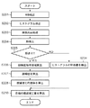
図2は静止画補正量演算部103で行う処理を示したフローチャートである。
S201では、WB検出部105がWB検出を行う。具体的には、WB検出部105は、画像データから、公知の手法を用いて、撮像画像に適したホワイトバランスのゲイン値を算出する。WB処理部115ではWB検出部105で得られたホワイトバランスのゲイン値を画像のRGBの各画素値に積算する。
FIG. 2 is a flowchart showing processing performed by the still image correction
In S201, the WB
S202では、ヒストグラム検出部106がヒストグラム検出を行う。具体的には、ヒストグラム検出部106が、S201で得られたホワイトバランスのゲイン値を画像データ全体に適用し、さらにガンマ補正処理を行った画素値について、輝度情報としてヒストグラムを作成する。ガンマ補正処理は公知のルックアップテーブルを用いる方法で良いが、現像処理部116で用いるものと同じガンマ特性を用いることが好ましい。ただし、処理時間やメモリ量の節約のために、折れ線で近似したガンマ特性など、簡略化したガンマ特性を用いてもよい。なお、画像の端の部分は、一般に重要でないことが多く、また撮像レンズによっては周辺光量の低下の影響を受ける部分であるため、周縁部の画素を除いてヒストグラムを作成してもよい。
In S202, the
S203では、顔検出部107が顔検出前処理を行う。これは画像データに対して縮小処理、ガンマ処理等を施して、顔を容易に検出しやすいようにする処理である。
In S203, the
S204で、顔検出部107は、前処理した画像データに対し、公知の方法を用いて顔検出処理を実行する。顔検出処理により、顔と思われる領域(顔領域)と、検出の信頼度とが得られる。
In S204, the
S205で、顔検出部107は、S204の顔検出処理により検出された顔領域のうち、信頼度があらかじめ設定した評価閾値より高い顔領域がある場合に、顔が検出されたと判定する。顔が検出されたと判定された場合にはS206に、顔が検出されなかったと判定された場合にはS209に移行する。
In S205, the
S206で、顔検出部107は、検出された顔領域の一部の領域を、顔輝度取得領域として算出する。たとえば、顔検出部107は、図3に示すように、画像データ301から検出された顔領域302の中の両眼の下の領域303,305及び、その中間の領域304の3箇所に位置する同じ大きさの正方形の領域を、顔輝度取得領域として算出する。個々の領域の大きさは、顔領域の大きさによって決定する。顔輝度取得領域は、顔の明るい部分の輝度を取得するための領域であり、その数や位置などに関して特に制限はない。
In step S206, the
S207で、顔検出部107は、顔輝度取得領域303〜305の各々について、含まれるR画素、G画素、B画素の種類ごとに平均値を求める。さらに顔検出部107はRGB画素の各平均値に対し、ヒストグラム検出部106と同様にしてホワイトバランスのゲイン値を適用し、ガンマ補正を行った後、以下の式1により輝度値Yに変換する。
Y=0.299×R+0.587×G+0.114×B 式1
なお、式1の代わりに式2のような近似式を用いても良い。
Y=(3×R+6×G+B)/10 式2
In S207, the
Y = 0.299 × R + 0.587 × G + 0.114 ×
An approximate expression such as
Y = (3 × R + 6 × G + B) / 10
なお、ヒストグラム検出部106および顔検出部107において適用するホワイトバランスのゲイン値は、同一画像データに対してWB検出部105が求めたゲイン値を用いることが好ましい。輝度ガンマも、理想的には現像処理部116と同じものを用いるのが好ましいが、処理時間やメモリ量の節約のために、折れ線で近似したガンマ特性など、簡略化したガンマ特性を用いてもよい。
Note that the gain value obtained by the
S208で、輝度算出手段としての顔検出部107は、検出された顔の代表輝度値を算出する。この処理の一例を図4のフローチャートを用いて説明する。
S401で、顔検出部107は、検出されている顔領域の顔輝度取得領域303〜305の輝度値の中から最大値を求める。なお、顔領域が複数検出されていれば、顔検出部107は個々の顔領域について最大値を求める。
In step S208, the
In step S401, the
S402で、顔検出部107は、顔領域が複数検出されているか判定し、複数検出されている場合はS403に処理を進める。検出されている顔領域が1つだけの場合、顔検出部107は、この顔領域についてS401で求めた輝度値の最大値を顔の代表輝度値とする(S408)。
In step S402, the
S403で、顔検出部107は、検出されている全ての顔領域における輝度値の最大値Yaを求める。
S404で、顔検出部107は、S401で求めた各顔領域の輝度の最大値の平均値Ybを求める。
In step S403, the
In step S404, the
S405で、顔検出部107は、顔領域で検出された最大輝度値Yaと顔領域で検出された平均輝度値Ybに対して所定の重みをかけた重み平均輝度値Ycを求める。
すなわち、Yc=(α×Ya+β×Yb)
として求めることができる。ここで、α、βは所定の重みで、α+β=1である。
なお、重みの値は、一番明るい顔をどの程度重視するかに応じて経験的にαを定めることで決定することができる。一例として、α=0.7、β=0.3である。
In step S405, the
That is, Yc = (α × Ya + β × Yb)
Can be obtained as Here, α and β are predetermined weights, and α + β = 1.
The weight value can be determined by empirically determining α according to how much importance is given to the brightest face. As an example, α = 0.7 and β = 0.3.
S406で、顔検出部107は、顔領域の最大輝度値Yaと重み平均輝度値Ycの差が、所定の閾値Ythより小さいかどうかの判定を行う。
顔検出部107は、この差が閾値より小さい場合は重み平均輝度値Ycを顔の代表輝度値とし(S407)、差が閾値以上である場合には最大輝度値Yaから閾値Ythを引いた値を顔の代表輝度値とする(S408)。これは、差が閾値Yth以上ある場合に、重み平均輝度値Ycを代表輝度値とすると、最大輝度値Yaに対応する顔領域が階調補正によって白トビする可能性が高くなると考えられるためである。従って、閾値Ythにはこのような判定を行うために適切な値を経験的に定める。
In step S406, the
When the difference is smaller than the threshold, the
図2に戻り、S205で顔領域が検出されなかったと判定された場合、S209でヒストグラム検出部106が、ヒストグラム特徴量を検出する。ヒストグラム特徴量は例えば、ヒストグラムで暗部側から累積度数が1%である画素が属するレベル(SD)、同10%である画素が属するレベル(SD2)、明部側から累積度数が1%である画素が属するレベル(HL)等であってよい。
Returning to FIG. 2, if it is determined in S205 that no face area has been detected, the
S210で、目標補正量算出部108は、目標の補正量の算出を行う。目標補正量算出部108は、顔が検出されている場合、顔の代表輝度値毎に、いくつかの入力輝度値に対する目標輝度を求め、目標輝度と画像の輝度の最小値と最大値からスプライン補間などにより各入力輝度に対する目標出力輝度を算出する。入力輝度と目標出力輝度の差が目標補正量であり、各輝度に対する目標出力輝度により形成されるトーンカーブが階調補正特性を表す。階調補正特性は、入力輝度と出力輝度の対応を示すルックアップテーブルによって表現することができる。なお、本明細書において、顔の代表輝度値とその目標値とからルックアップテーブルを作成することを便宜上「顔補正特性の作成」と呼ぶ。
In step S210, the target correction
図5を参照して目標補正量算出部108の顔補正特性の作成動作の例を説明する。図5(a)は、顔の代表輝度値と、3つの入力輝度値(64LSB,128LSB,224LSB)に対する目標輝度との関係の例を示す。なお、LSBは分解能を意味し、本実施形態では輝度値のフルスケール(最小値〜最大値)を8ビットの分解能(0〜255LSB)で表すものとする。
An example of the operation of creating the face correction characteristic of the target correction
図5(a)において、「64LSBの点」に対応する横方向の線は、入力輝度が64LSBの画素の目標出力輝度と、顔の代表輝度値との関係を示している。例えば、撮像された画像から検出された顔の代表輝度値が255LSB〜180LSBの範囲であれば、その画像のうち64LSBの輝度を有する画素の目標出力輝度は64LSB(すなわち、変化無し)である。また、顔の代表輝度値が45LSB〜0LSBの範囲の画像においては、64LSBの輝度を有する画素の目標出力輝度は128LSBである。そして、顔の代表輝度値が180〜45の範囲では、64LSBの輝度を有する画素の目標出力輝度は64LSBから128LSBの間で線形に変化する。 In FIG. 5A, the horizontal line corresponding to “64 LSB point” indicates the relationship between the target output luminance of the pixel having the input luminance of 64 LSB and the representative luminance value of the face. For example, if the representative luminance value of the face detected from the captured image is in the range of 255 LSB to 180 LSB, the target output luminance of a pixel having a luminance of 64 LSB in the image is 64 LSB (that is, no change). In addition, in an image whose face representative luminance value is in the range of 45 LSB to 0 LSB, the target output luminance of a pixel having a luminance of 64 LSB is 128 LSB. When the face representative luminance value is in the range of 180 to 45, the target output luminance of a pixel having a luminance of 64 LSB changes linearly between 64 LSB and 128 LSB.
顔の代表輝度値が110LSBである場合、64LSB、128LSBおよび224LSBの輝度を有する画素の目標出力輝度はそれぞれ図5(a)から97LSB,159LSBおよび228LSBである。従って、顔の代表輝度値が110LSBの画像に対する階調補正特性は、この3点の入出力関係を表す3点と輝度の最低値(0LSB)および最高値(255LSB)に対応する点とをスプライン補間することにより、図5(b)の様に得られる。なお、図5(a)に示す、顔の代表輝度値に応じた代表的な輝度値の入出力関係を示す補正テーブルは、補正度合い設定部104で設定可能な度合いごとに、予め目標補正量算出部108に用意しておくことができる。
When the representative brightness value of the face is 110LSB, the target output brightness of the pixels having the brightness of 64LSB, 128LSB and 224LSB are 97LSB, 159LSB and 228LSB from FIG. 5 (a), respectively. Therefore, the gradation correction characteristic for an image having a face representative luminance value of 110 LSB is a spline of three points representing the input / output relationship of the three points and the point corresponding to the lowest value (0LSB) and the highest value (255LSB). By interpolating, it is obtained as shown in FIG. It should be noted that the correction table showing the input / output relationship of the representative luminance value according to the representative luminance value of the face shown in FIG. 5A is set in advance for each degree that can be set by the correction
また、顔が検出されなかった画像に対する階調補正特性の算出方法について図6を用いて説明する。まず、図6(a)〜図6(c)は、SD、HLおよびSD2についての目標出力輝度を規定するテーブルを示す。このテーブルは、予め目標補正量算出部108に用意しておくことができる。なお、図5(a)及び図6(a)〜(c)に示すテーブルは、設定可能な階調補正の程度(例えば「弱い」、「標準」、「強い」)ごとに用意する。あるいは、基準となる1つのテーブルと、基準となるテーブルから他の程度のテーブルを精製するための係数を用意しておいてもよい。
A method for calculating gradation correction characteristics for an image in which no face has been detected will be described with reference to FIG. First, FIG. 6A to FIG. 6C show tables defining the target output luminance for SD, HL, and SD2. This table can be prepared in the target correction
まず、目標補正量算出部108は、ヒストグラム検出部106で求められたSDとHLに対応する目標出力輝度を図6(a)及び図6(b)から求める。そして、目標補正量算出部108は、図6(d)に示すように、SDとHLの入出力特性に対応する点(丸、四角)と、画像の輝度の最小値(0LSB)と最大値(255LSB)に対応する点の4点を折れ線で結んだ補正特性を求める。この補正特性を、便宜上、コントラスト補正特性と呼ぶ。また、目標補正量算出部108は、SD2についても図6(c)から目標出力輝度を求める。そして、目標補正量算出部108、図6(e)に示すように、SD2の入出力特性に対応する点(三角)と画像の輝度の最小値と最大値に対応する点の3点をスプライン補間して得られる補正特性を求める。この補正特性を便宜上、暗部補正特性と呼ぶ。
First, the target correction
そして、目標補正量算出部108は、コントラスト補正特性と暗部補正特性とを合成して最終的な階調補正特性(目標補正特性)を作成する(図6(f))。この合成は、各補正を順次適用した場合と同じ結果が1回の補正で得られるように各補正特性を合成することにより実現できる。
Then, the target correction
目標補正量算出部108は、このようにして求めた図6(f)に示す階調補正特性を、ルックアップテーブル(又は関係式)として保存する。目標補正量算出部108は、このようにして作成した階調補正用のルックアップテーブル(あるいは補正特性を表す関数など、他の形式であってもよい)を、WB処理部115及び動画補正量演算部109の目標補正量修正部110に供給する。
The target correction
なお、静止画補正量演算部103における上述の目標補正量算出処理は、撮像部101が撮像する動画(ライブビュー画像含む)の各フレームに対して行ってもよいし、予め定められた規則に従って間欠的に実行してもよい。
Note that the target correction amount calculation processing in the still image correction
図1の動画補正量演算部109では、以上のようにして算出された階調補正特性をもとに、動画またはライブビュー表示用画像に適用する補正量を算出する。
動画補正量演算部109は、目標補正量修正部110、第1のメモリ111、現在補正量算出部112、第2のメモリ113から成る。
The moving image correction
The moving image correction
目標補正量修正部110では、静止画補正量演算部103で算出された階調補正特性の変動を抑制するように、ヒステリシス処理を行う。具体的には、目標補正量修正部110は、第1のメモリ111に記憶してある前回適用した階調補正特性と、静止画補正量演算部103で算出された階調補正特性とを入力輝度ごとに比較する。補正量の差(出力輝度値の差)がある閾値以内であれば、目標補正量修正部110は、前回の補正量を目標補正量として用いて修正し、閾値以上であれば、今回算出された目標補正量をそのまま用いて修正する。ここで用いる閾値は、たとえば輝度ごとにテーブルに登録して用意しておくことができる。
The target correction
目標補正量修正部110は、次回の比較処理に用いるため、修正した階調補正特性を第1のメモリ111に記憶する。
現在補正量算出部112は、修正された階調補正特性と、前フレームに適用した階調補正特性とから、急激に補正量が変わらず、段階的に目標の階調補正特性に達するように、次フレームで行う階調補正特性を算出する。
The target correction
The current correction
具体的には、現在補正量算出部112は、前フレームに適用した階調補正特性から、目標となる階調補正特性に向かって少し近づくための階調補正特性を次フレームに適用する階調補正特性として算出する。この算出は以下のように行うことができる。たとえば、現在補正量算出部112は、前フレームに適用した各輝度に対する補正量と、次フレームに適用する補正量に対して許容する最大変化量をテーブルとして保持しておく。そして、現在補正量算出部112は、目標となる階調補正特性における補正量と、前フレームで適用した補正量との差分が最大変化量以内であれば、目標となる階調補正量が適用されるように補正量を決定する。
Specifically, the current correction
また、現在補正量算出部112は、目標となる階調補正特性における補正量と、前フレームで適用した補正量との差分が最大変化量を超えるならば、前フレームので適用した補正量に最大変化量分だけ増減させた補正量を算出する。この処理を各入力輝度に対して行うことで、現在補正量算出部112は階調補正特性を算出する。現在補正量算出部112は、このようにして算出された階調補正特性を、次フレーム用の階調補正特性を算出する際に用いるために第2のメモリ113に記憶するとともに、現像処理部116に供給する。
Further, the current correction
現像処理部116は、現在補正量算出部112から供給される階調補正特性を、ライブビュー画像、記録用の動画の各フレーム画像、ライブビュー表示中や動画記録中に撮像された静止画に適用する。
The
本実施形態のデジタルビデオカメラは、RAW形式の静止画撮像時には、他設定補正量算出部114で、撮像時における階調補正度合いと異なる階調補正度合いに対応する補正量の算出を行う。これにより、撮像時における階調補正特性と補正度合いとの関係を壊すことなく、後で階調補正度合いを変更することが可能になる。
In the digital video camera of the present embodiment, when a RAW format still image is captured, the other setting correction
他設定補正量算出部114の動作について、図7及び図8を参照して説明する。
S701で、他設定補正量算出部114は、撮像時における階調補正特性(上述の通り、コントラスト補正特性と暗部補正特性が合成されたものである)のうち、暗部補正特性を見積もる。この見積もりは、撮像時における階調補正特性と、予め定められている暗部補正特性の特定の輝度における補正量の比とを用いて行うことができる。
The operation of the other setting correction
In step S <b> 701, the other setting correction
図6(d)〜(f)からもわかるように、階調補正特性のうち、中間輝度部分の補正量は暗部補正特性(図6(e))によるものが支配的である。また、暗部補正特性において、中間輝度部分のある特定輝度(例えば100LSB)に対応する補正量と、シャドウ部におけるある特定輝度(例えば32LSB)に対応する補正量との比は固定と見なすことができる。 As can be seen from FIGS. 6D to 6F, among the gradation correction characteristics, the correction amount of the intermediate luminance portion is predominantly based on the dark area correction characteristics (FIG. 6E). In the dark portion correction characteristics, the ratio between the correction amount corresponding to a certain luminance (for example, 100 LSB) having an intermediate luminance portion and the correction amount corresponding to a certain luminance (for example, 32 LSB) in the shadow portion can be regarded as fixed. .
他設定補正量算出部114は、撮像時における階調補正特性(図8(a))のうち、中間輝度部分の特定輝度Xに対応する補正量αと、シャドウ部における特定輝度Yに対応する補正量βとを取得する。そして、他設定補正量算出部114は、補正量αより小さな補正量α’と、補正量βより小さな補正量β’であって、かつその比(例えばβ’/α’)が、予め定めた比を満たす補正量α’とβ’を求める。
そして、他設定補正量算出部114は、この補正量α’とβ’に対応する点と、0LSB及び255LSBに対応する点とを補間して、暗部補正特性を見積もる(図8(c))。
The other setting correction
Then, the other set correction
S702で、他設定補正量算出部114は、撮像時における階調補正特性(図8(a))から、S701で見積もった暗部補正特性を分離し、コントラスト補正特性とする。
In S702, the other setting correction
S703で、他設定補正量算出部114は、分離された各補正特性を、撮像時に設定された補正の度合いとの差異に応じて補正することにより、撮像時に設定された補正の度合いと異なる度合いに対応した補正特性を算出する。具体的には、図6(a)〜(c)に示したSD、HL、SD2の目標出力輝度を規定するテーブルを、補正の度合い(例えば「弱め」、「標準」、「強め」)毎に用意しておく。あるいは、各入力輝度値について、「標準」の値に対する補正比率を「弱め」、「強め」について用意しておく。そして、他設定補正量算出部114は、分離されたコントラスト補正特性における、SD、HLに対応する出力輝度値を当該比率を用いて修正してコントラスト補正特性を作成することにより、コントラスト補正特性を修正する(図8(d))。暗部補正特性についても同様に、SD2に対する出力輝度値を修正して暗部補正特性を作成することにより修正する(図8(e))。
In step S <b> 703, the other setting correction
S704で、他設定補正量算出部114は、修正された各補正特性を合成する(図8(f))。
S705で、他設定補正量算出部114は、合成した補正特性にリミッター処理を適用する(図8(f))。具体的には、各階調補正の度合いに対応する最大の補正量を輝度毎に保持しておき、各輝度値についてこの最大補正量を超えていればクリップ処理を行うようにする。このようにして、撮像時に設定された補正の度合いと異なる度合いに対応した補正特性を得る。
In step S704, the other setting correction
In step S <b> 705, the other setting correction
なお、ここでは、精度よく修正を行うためにコントラスト補正特性と暗部補正特性とに分離し、個々の補正特性を修正した後に再度合成する方法を説明した。しかしながら、より簡易的な処理で代用してもよい。この場合、コントラスト補正特性と暗部補正特性への分離は行わずに、撮像時における階調補正特性の各輝度値に対し、補正の程度に対応した所定の補正係数を積算することで、撮像時とは異なる階調補正の程度に対応する階調補正特性を求めることができる。図9は、撮像時には階調補正の度合いが「標準」に設定されていた場合に、「強め」の度合いに対応する階調補正特性を算出する簡易的な方法を模式的に示している。 Here, a method has been described in which the contrast correction characteristic and the dark part correction characteristic are separated in order to correct with high accuracy, and the individual correction characteristics are corrected and then combined again. However, a simpler process may be used instead. In this case, the contrast correction characteristic and the dark part correction characteristic are not separated, and a predetermined correction coefficient corresponding to the degree of correction is added to each luminance value of the gradation correction characteristic at the time of imaging, so that an image is captured. It is possible to obtain gradation correction characteristics corresponding to the degree of gradation correction different from the above. FIG. 9 schematically shows a simple method for calculating the gradation correction characteristic corresponding to the degree of “strong” when the degree of gradation correction is set to “standard” at the time of imaging.
また、動画記録、ライブビュー表示、またはRAW記録モード以外の静止画撮像時では、撮像時に設定されていた階調補正の度合いと異なる度合いの補正特性を算出する必要がないので、他設定補正量算出部114による撮像時の処理を省略しても構わない。また、処理負荷の軽減や電池の節約などを目的として、他設定補正量算出部114を動作させないようにしてもよい。この場合、撮像時に設定されていた階調補正の度合いと異なる度合いの補正特性は、再現像時に算出すればよい。
In addition, when shooting still images other than moving image recording, live view display, or RAW recording mode, it is not necessary to calculate a correction characteristic with a degree different from the gradation correction level set at the time of imaging. The processing at the time of imaging by the
画像データ出力部117は、現像処理部116が出力する現像済みの画像データをファイル化して出力する。例えば、画像データ出力部117は、ファイル形式をJPEGファイルに変換する場合には、画像データをYCrCb形式に3次元マトリックス変換して付属データを添付することでJPEGファイル形式に変換する。RAW形式で記録する場合、画像データ出力部117は、RAW画像データを含んだ画像ファイルを生成する。RAW画像データを含んだ画像ファイルのヘッダにサムネイル用のJPEG形式の画像を含めてもよい。画像データ出力部117は、画像ファイルをメモリカードのような記録媒体に記録したり、外部装置に出力したりすることができる。
The image
また、画像データ出力部117は、他設定補正量算出部114で撮像時と異なる階調補正の度合いに対応する補正特性を算出した場合には、この補正特性を表す情報(テーブル等)と、対応する階調補正の度合いを画像ファイルのヘッダー等に記録する。また、画像データ出力部117は撮像時における階調補正特性を表す情報と、撮像時に設定されていた階調補正の度合いを表す情報も付属情報として画像ファイルのヘッダなどに含める。
In addition, when the other setting correction
以上のようにして生成された画像ファイルを再現像する場合の動作について図1(b)を用いて説明する。なお、画像ファイルの生成と再現像とは異なる装置で実行されてもよい。例えば、画像ファイルの生成は撮像装置で行い、再現像はパーソナルコンピュータで現像アプリケーションを動作させて行うことができる。この場合、図1(b)の各機能ブロックのうち、WB処理部115、現像処理部116及び画像データ出力部117はソフトウェア的に実現される。また、補正度合い設定部104はキーボードやマウスなどの入力デバイスであってよい。
The operation when the image file generated as described above is re-developed will be described with reference to FIG. Note that image file generation and redevelopment may be performed by different apparatuses. For example, an image file can be generated by an imaging apparatus, and redevelopment can be performed by operating a development application on a personal computer. In this case, among the functional blocks in FIG. 1B, the
WB処理部115は、画像ファイルに含まれるRAW形式の画像データに対し、ホワイトバランスのゲイン値を画像のRGBの各画素値に積算する。これは撮像時と同じゲイン値でも良いし、異なる値に設定しなおしても良い。
The
現像処理部116は、補正度合い設定部104を通じてユーザが設定した度合いに対応する階調補正特性を、画像ファイルのヘッダから取得し、RAW画像データに適用する。なお、他設定補正量算出部114が補正特性を算出していない場合、画像ファイルのヘッダに、対応する度合いの階調補正特性を表すデータが記録されていない。このような場合に対応可能とするには、図1(b)の構成に他設定補正量算出部114を追加する。そして、画像ファイルのヘッダに、対応する度合いの階調補正特性を表すデータが記録されていない場合には、撮像時における階調補正特性を表す情報と、対応する補正度合いを表す情報から、他設定補正量算出部114が階調補正特性を算出する。現像処理部116は、他設定補正量算出部114が算出した補正特性を画像データに適用する。
The
画像データ出力部117は、上述の撮像時の処理と同様に、設定された画像ファイルの形式に応じた画像ファイルを生成して出力する。
The image
以上説明したように、本実施形態によれば、撮像時に階調補正された静止画の階調補正の程度を変更する際に、撮像時における階調補正特性を基準として変更後の階調補正特性を算出する。そのため、静止画がライブビュー表示中や動画記録中に撮像され、目標の階調補正特性に達していない遷移状態で撮像されたものであったとしても、階調補正の程度を、動画との見えの差が少なく、またユーザの意図に沿って変更することができる。 As described above, according to the present embodiment, when the degree of gradation correction of a still image that has been gradation corrected at the time of imaging is changed, the gradation correction after the change is performed based on the gradation correction characteristics at the time of imaging. Calculate the characteristics. Therefore, even if a still image was captured during live view display or during moving image recording and was captured in a transition state that did not reach the target gradation correction characteristics, The difference in appearance is small and can be changed according to the user's intention.
本発明は特に、動画記録中に撮像された静止画であって、かつAEロックして撮像された静止画に対して好適である。これは、撮像時のAEロックは、ユーザが画像の明るさを一定に保ちたいという意志の現れであり、記録される動画と静止画の見えの同一性が一層要求されるからである。この場合には、階調補正特性もAEロック時に固定するべきである。 The present invention is particularly suitable for still images captured during moving image recording and captured by AE lock. This is because the AE lock at the time of imaging is a manifestation of the user's intention to keep the brightness of the image constant, and the appearance of the recorded moving image and the still image is further required to be identical. In this case, the gradation correction characteristic should also be fixed when the AE is locked.
従って、上述した、撮像時における階調補正特性を基準とした、変更後の階調補正特性の算出処理を、撮像時にAEロックされている場合のみ実行するように構成してもよい。撮像時にAEロックされているかどうかは、画像ファイルの付属情報(例えばexif情報)や、AEロックボタンが押下されたかどうかの検出(本発明を撮像装置に適用した場合)などによって判別することができる。 Therefore, the above-described calculation process of the gradation correction characteristic after the change based on the gradation correction characteristic at the time of imaging may be executed only when the AE lock is performed at the time of imaging. Whether or not the AE is locked at the time of imaging can be determined by the attached information (for example, exif information) of the image file, detection of whether or not the AE lock button is pressed (when the present invention is applied to the imaging apparatus), and the like. .
また、本発明は、以下の処理を実行することによっても実現される。即ち、上述した実施形態の機能を実現するソフトウェア(プログラム)を、ネットワーク又は各種記憶媒体を介してシステム或いは装置に供給し、そのシステム或いは装置のコンピュータ(またはCPUやMPU等)がプログラムを読み出して実行する処理である。 The present invention can also be realized by executing the following processing. That is, software (program) that realizes the functions of the above-described embodiments is supplied to a system or apparatus via a network or various storage media, and a computer (or CPU, MPU, or the like) of the system or apparatus reads the program. It is a process to be executed.
Claims (18)
前記撮像時における階調補正特性を表すデータを取得する取得手段と、
前記取得手段により取得されたデータが表わす階調補正特性が前記撮像時に設定されていた階調補正の度合いに応じた目標階調補正特性と異なる場合、前記撮像時に設定されていた階調補正の度合いと前記異なる度合いとの差異に応じて、前記取得手段により取得されたデータが表わす階調補正特性を補正することにより、前記異なる度合いの階調補正を適用するための階調補正特性を算出する補正手段とを有することを特徴とする画像処理装置。 An image processing apparatus for generating gradation correction characteristics for applying gradation correction with a degree different from the degree of gradation correction set at the time of imaging to image data obtained by imaging,
Acquisition means for acquiring data representing gradation correction characteristics at the time of imaging;
If the gradation correction characteristic represented by the data acquired by the acquisition unit is different from the target gradation correction characteristic corresponding to the degree of gradation correction set at the time of imaging , the gradation correction characteristic set at the time of imaging is corrected. depending on the difference between the degree and the previous SL different degrees, by correcting the gradation correction characteristic represented by the data acquired by the acquisition unit, the gradation correction characteristic for applying tone correction of the different degrees An image processing apparatus comprising: a correcting unit that calculates.
前記撮像時における階調補正特性を、第1の補正特性と、前記第1の補正特性とは異なる第2の補正特性とに分離し、
前記第1の補正特性と前記第2の補正特性を、前記撮像時に設定されていた階調補正の度合いと、前記異なる度合いとの差異に応じてそれぞれ補正し、
前記補正した前記第1の補正特性と前記第2の補正特性を合成することにより、前記撮像時に設定されていた階調補正の度合いと異なる度合いの階調補正を適用するための階調補正特性を算出することを特徴とする請求項1記載の画像処理装置。 The correction means is
Separating the gradation correction characteristic at the time of imaging into a first correction characteristic and a second correction characteristic different from the first correction characteristic;
Correcting the first correction characteristic and the second correction characteristic in accordance with the difference between the gradation correction level set at the time of imaging and the different level,
A gradation correction characteristic for applying gradation correction with a degree different from the degree of gradation correction set at the time of imaging by combining the corrected first correction characteristic and the second correction characteristic. The image processing apparatus according to claim 1, wherein:
前記第2の補正特性は、前記輝度ヒストグラムにおいて暗部側からの累積度数が前記第1の値及び前記第2の値とは異なる第3の値となるレベルに基づく補正特性であることを特徴とする請求項8に記載の画像処理装置。 The first correction characteristic includes a level at which the cumulative frequency from the dark portion side in the luminance histogram becomes a first value, and a second value in which the cumulative frequency from the dark portion side in the luminance histogram is different from the first value. Correction characteristics based on the level
The second correction characteristic is a correction characteristic based on a level at which the cumulative frequency from the dark side in the luminance histogram is a third value different from the first value and the second value. The image processing apparatus according to claim 8 .
前記撮像時に設定されていた階調補正の度合いと、前記異なる度合いとの関係によって予め定められた補正係数によって前記撮像時における階調補正特性を補正することにより、前記異なる度合いの階調補正を適用するための階調補正特性を算出することを特徴とする請求項1記載の画像処理装置。 The correction means is
By correcting the gradation correction characteristics at the time of imaging with a correction coefficient determined in advance by the relationship between the degree of gradation correction set at the time of imaging and the different degree, the gradation correction at the different degrees is performed. The image processing apparatus according to claim 1, wherein a gradation correction characteristic to be applied is calculated.
前記撮像時における階調補正特性を表すデータを取得する取得手段と、
前記撮像時に設定されていた階調補正の度合いと、前記異なる度合いとの差異に応じて前記階調補正特性を補正することにより、前記異なる度合いの階調補正を適用するための階調補正特性を算出する補正手段と、
前記撮像時にAEロックされていたかどうかを判別する判別手段と、を有し、
前記補正手段は、
前記撮像時にAEロックされていた場合には、前記撮像時に設定されていた階調補正の度合いと、前記異なる度合いとの差異に応じて前記階調補正特性を補正することにより、前記異なる度合いの階調補正を適用するための階調補正特性を算出し、前記撮像時にAEロックされていなかった場合には、前記画像データの輝度情報に基づいて前記異なる度合いの階調補正を適用するための階調補正特性を算出することを特徴とする画像処理装置。 An image processing apparatus for generating gradation correction characteristics for applying gradation correction with a degree different from the degree of gradation correction set at the time of imaging to image data obtained by imaging,
Acquisition means for acquiring data representing gradation correction characteristics at the time of imaging;
A gradation correction characteristic for applying the gradation correction of the different degree by correcting the gradation correction characteristic according to a difference between the gradation correction degree set at the time of imaging and the different degree Correction means for calculating
Anda judging means for judging whether or not the AE lock during the imaging,
The correction means includes
When the AE lock is performed at the time of image capturing, the gradation correction characteristic is corrected according to the difference between the degree of gradation correction set at the time of image capturing and the different degree. A gradation correction characteristic for applying gradation correction is calculated, and when the AE lock is not performed at the time of imaging, the gradation correction of the different degree is applied based on the luminance information of the image data. images processor you and calculates the gradation correction characteristic.
取得手段が、前記撮像時における階調補正特性を表すデータを取得する取得工程と、
補正手段が、前記取得工程で取得されたデータが表わす階調補正特性が前記撮像時に設定されていた階調補正の度合いに応じた目標階調補正特性と異なる場合、前記撮像時に設定されていた階調補正の度合いと前記異なる度合いとの差異に応じて、前記取得工程で取得されたデータが表わす階調補正特性を補正することにより、前記異なる度合いの階調補正を適用するための階調補正特性を算出する補正工程とを有することを特徴とする画像処理方法。 An image processing method for generating gradation correction characteristics for applying gradation correction with a degree different from the gradation correction degree set at the time of imaging to image data obtained by imaging,
An obtaining step for obtaining data representing gradation correction characteristics at the time of imaging;
If the gradation correction characteristic represented by the data acquired in the acquisition step is different from the target gradation correction characteristic corresponding to the degree of gradation correction set at the time of imaging , the correction unit is set at the time of imaging. depending on the difference between the degree and the previous SL different degrees of gradation correction, by correcting the gradation correction characteristic represented by the data acquired by said acquisition step, floors for applying tone correction of the different degrees And a correction step for calculating a tone correction characteristic.
請求項1乃至請求項15のいずれか1項に記載の画像処理装置と、
を有することを特徴とする撮像装置。 An imaging unit that captures an optical image of the subject and generates image data ;
An image processing apparatus according to any one of 請 Motomeko 1 to claim 15,
Imaging apparatus characterized by having a.
Priority Applications (1)
| Application Number | Priority Date | Filing Date | Title |
|---|---|---|---|
| JP2010185579A JP5743456B2 (en) | 2010-08-20 | 2010-08-20 | Image processing apparatus, image processing method, and imaging apparatus |
Applications Claiming Priority (1)
| Application Number | Priority Date | Filing Date | Title |
|---|---|---|---|
| JP2010185579A JP5743456B2 (en) | 2010-08-20 | 2010-08-20 | Image processing apparatus, image processing method, and imaging apparatus |
Publications (3)
| Publication Number | Publication Date |
|---|---|
| JP2012044560A JP2012044560A (en) | 2012-03-01 |
| JP2012044560A5 JP2012044560A5 (en) | 2013-09-19 |
| JP5743456B2 true JP5743456B2 (en) | 2015-07-01 |
Family
ID=45900321
Family Applications (1)
| Application Number | Title | Priority Date | Filing Date |
|---|---|---|---|
| JP2010185579A Expired - Fee Related JP5743456B2 (en) | 2010-08-20 | 2010-08-20 | Image processing apparatus, image processing method, and imaging apparatus |
Country Status (1)
| Country | Link |
|---|---|
| JP (1) | JP5743456B2 (en) |
Families Citing this family (3)
| Publication number | Priority date | Publication date | Assignee | Title |
|---|---|---|---|---|
| JP6060498B2 (en) * | 2012-02-29 | 2017-01-18 | 株式会社ニコン | Correction device |
| JP2014011767A (en) * | 2012-07-03 | 2014-01-20 | Olympus Imaging Corp | Imaging device and imaging method |
| CN113794816B (en) * | 2021-08-04 | 2023-05-23 | 成都市联洲国际技术有限公司 | Image enhancement method, device, equipment and storage medium in dim light environment |
Family Cites Families (5)
| Publication number | Priority date | Publication date | Assignee | Title |
|---|---|---|---|---|
| JP2002107788A (en) * | 2000-10-02 | 2002-04-10 | Konica Corp | Electronic camera |
| JP4383004B2 (en) * | 2001-04-27 | 2009-12-16 | オリンパス株式会社 | Electronic camera |
| JP2004112473A (en) * | 2002-09-19 | 2004-04-08 | Matsushita Electric Ind Co Ltd | Gradation corrector |
| JP4895839B2 (en) * | 2006-02-01 | 2012-03-14 | 富士フイルム株式会社 | Image correction apparatus and method |
| JP4992963B2 (en) * | 2009-12-17 | 2012-08-08 | カシオ計算機株式会社 | Still image generating apparatus, still image generating program, and still image generating method |
-
2010
- 2010-08-20 JP JP2010185579A patent/JP5743456B2/en not_active Expired - Fee Related
Also Published As
| Publication number | Publication date |
|---|---|
| JP2012044560A (en) | 2012-03-01 |
Similar Documents
| Publication | Publication Date | Title |
|---|---|---|
| US20200260001A1 (en) | Global Tone Mapping | |
| US8363131B2 (en) | Apparatus and method for local contrast enhanced tone mapping | |
| JP5100565B2 (en) | Image processing apparatus and image processing method | |
| US8488015B2 (en) | Camera using preview image to select exposure | |
| US9426437B2 (en) | Image processor performing noise reduction processing, imaging apparatus equipped with the same, and image processing method for performing noise reduction processing | |
| EP2426928A2 (en) | Image processing apparatus, image processing method and program | |
| US20060215908A1 (en) | Image pickup apparatus and image processing method | |
| KR20080035981A (en) | Image processing apparatus, imaging apparatus, image processing method, and computer program | |
| EP2426927A2 (en) | Image processing apparatus, image processing method and recording medium | |
| WO2006120864A1 (en) | Image processing device, and image processing program | |
| KR20110004791A (en) | Image processing apparatus and computer-readable medium | |
| JP2011003048A (en) | Image processing apparatus and image processing program | |
| WO2009060970A1 (en) | Signal processing apparatus and signal processing program | |
| JP5782311B2 (en) | Imaging apparatus and control method thereof | |
| JP2012165204A (en) | Signal processing apparatus, signal processing method, imaging apparatus, and imaging processing method | |
| US20100295977A1 (en) | Image processor and recording medium | |
| JP6904788B2 (en) | Image processing equipment, image processing methods, and programs | |
| KR20110125170A (en) | Apparatus and method for auto adjusting brightness of image taking device | |
| WO2008056566A1 (en) | Image signal processing apparatus, image signal processing program and image signal processing method | |
| JP5743456B2 (en) | Image processing apparatus, image processing method, and imaging apparatus | |
| JP5315125B2 (en) | Image processing apparatus, imaging apparatus, and composite image generation method | |
| JP5591026B2 (en) | Imaging apparatus and control method thereof | |
| JP5932392B2 (en) | Image processing apparatus and image processing method | |
| JP5706705B2 (en) | Image processing apparatus, control method therefor, and imaging apparatus | |
| JP5225491B2 (en) | Image processing apparatus and image processing method |
Legal Events
| Date | Code | Title | Description |
|---|---|---|---|
| A521 | Request for written amendment filed |
Free format text: JAPANESE INTERMEDIATE CODE: A523 Effective date: 20130814 |
|
| A621 | Written request for application examination |
Free format text: JAPANESE INTERMEDIATE CODE: A621 Effective date: 20130814 |
|
| A977 | Report on retrieval |
Free format text: JAPANESE INTERMEDIATE CODE: A971007 Effective date: 20140728 |
|
| A131 | Notification of reasons for refusal |
Free format text: JAPANESE INTERMEDIATE CODE: A131 Effective date: 20140829 |
|
| TRDD | Decision of grant or rejection written | ||
| A01 | Written decision to grant a patent or to grant a registration (utility model) |
Free format text: JAPANESE INTERMEDIATE CODE: A01 Effective date: 20150330 |
|
| A61 | First payment of annual fees (during grant procedure) |
Free format text: JAPANESE INTERMEDIATE CODE: A61 Effective date: 20150428 |
|
| R151 | Written notification of patent or utility model registration |
Ref document number: 5743456 Country of ref document: JP Free format text: JAPANESE INTERMEDIATE CODE: R151 |
|
| LAPS | Cancellation because of no payment of annual fees |