JP5884214B2 - Fan motor - Google Patents
Fan motor Download PDFInfo
- Publication number
- JP5884214B2 JP5884214B2 JP2012013943A JP2012013943A JP5884214B2 JP 5884214 B2 JP5884214 B2 JP 5884214B2 JP 2012013943 A JP2012013943 A JP 2012013943A JP 2012013943 A JP2012013943 A JP 2012013943A JP 5884214 B2 JP5884214 B2 JP 5884214B2
- Authority
- JP
- Japan
- Prior art keywords
- stator
- rotor
- rotating shaft
- enclosure
- side bearing
- Prior art date
- Legal status (The legal status is an assumption and is not a legal conclusion. Google has not performed a legal analysis and makes no representation as to the accuracy of the status listed.)
- Active
Links
- 238000003780 insertion Methods 0.000 claims description 11
- 230000037431 insertion Effects 0.000 claims description 11
- 230000036316 preload Effects 0.000 claims description 4
- 239000011162 core material Substances 0.000 description 13
- 230000002093 peripheral effect Effects 0.000 description 10
- 239000000428 dust Substances 0.000 description 4
- 239000000843 powder Substances 0.000 description 3
- 229910000976 Electrical steel Inorganic materials 0.000 description 2
- 238000010030 laminating Methods 0.000 description 2
- 239000007788 liquid Substances 0.000 description 2
- 239000000758 substrate Substances 0.000 description 2
- 239000011248 coating agent Substances 0.000 description 1
- 238000000576 coating method Methods 0.000 description 1
- 238000000748 compression moulding Methods 0.000 description 1
- 230000000694 effects Effects 0.000 description 1
- 238000000034 method Methods 0.000 description 1
- 239000011347 resin Substances 0.000 description 1
- 229920005989 resin Polymers 0.000 description 1
- XLYOFNOQVPJJNP-UHFFFAOYSA-N water Substances O XLYOFNOQVPJJNP-UHFFFAOYSA-N 0.000 description 1
Images

Classifications
-
- F—MECHANICAL ENGINEERING; LIGHTING; HEATING; WEAPONS; BLASTING
- F04—POSITIVE - DISPLACEMENT MACHINES FOR LIQUIDS; PUMPS FOR LIQUIDS OR ELASTIC FLUIDS
- F04D—NON-POSITIVE-DISPLACEMENT PUMPS
- F04D25/00—Pumping installations or systems
- F04D25/02—Units comprising pumps and their driving means
- F04D25/06—Units comprising pumps and their driving means the pump being electrically driven
- F04D25/0606—Units comprising pumps and their driving means the pump being electrically driven the electric motor being specially adapted for integration in the pump
-
- F—MECHANICAL ENGINEERING; LIGHTING; HEATING; WEAPONS; BLASTING
- F04—POSITIVE - DISPLACEMENT MACHINES FOR LIQUIDS; PUMPS FOR LIQUIDS OR ELASTIC FLUIDS
- F04D—NON-POSITIVE-DISPLACEMENT PUMPS
- F04D29/00—Details, component parts, or accessories
- F04D29/08—Sealings
- F04D29/083—Sealings especially adapted for elastic fluid pumps
-
- H—ELECTRICITY
- H02—GENERATION; CONVERSION OR DISTRIBUTION OF ELECTRIC POWER
- H02K—DYNAMO-ELECTRIC MACHINES
- H02K5/00—Casings; Enclosures; Supports
- H02K5/04—Casings or enclosures characterised by the shape, form or construction thereof
-
- F—MECHANICAL ENGINEERING; LIGHTING; HEATING; WEAPONS; BLASTING
- F04—POSITIVE - DISPLACEMENT MACHINES FOR LIQUIDS; PUMPS FOR LIQUIDS OR ELASTIC FLUIDS
- F04D—NON-POSITIVE-DISPLACEMENT PUMPS
- F04D25/00—Pumping installations or systems
- F04D25/02—Units comprising pumps and their driving means
- F04D25/06—Units comprising pumps and their driving means the pump being electrically driven
- F04D25/0606—Units comprising pumps and their driving means the pump being electrically driven the electric motor being specially adapted for integration in the pump
- F04D25/0613—Units comprising pumps and their driving means the pump being electrically driven the electric motor being specially adapted for integration in the pump the electric motor being of the inside-out type, i.e. the rotor is arranged radially outside a central stator
- F04D25/062—Details of the bearings
-
- F—MECHANICAL ENGINEERING; LIGHTING; HEATING; WEAPONS; BLASTING
- F04—POSITIVE - DISPLACEMENT MACHINES FOR LIQUIDS; PUMPS FOR LIQUIDS OR ELASTIC FLUIDS
- F04D—NON-POSITIVE-DISPLACEMENT PUMPS
- F04D29/00—Details, component parts, or accessories
- F04D29/05—Shafts or bearings, or assemblies thereof, specially adapted for elastic fluid pumps
- F04D29/056—Bearings
- F04D29/059—Roller bearings
-
- F—MECHANICAL ENGINEERING; LIGHTING; HEATING; WEAPONS; BLASTING
- F04—POSITIVE - DISPLACEMENT MACHINES FOR LIQUIDS; PUMPS FOR LIQUIDS OR ELASTIC FLUIDS
- F04D—NON-POSITIVE-DISPLACEMENT PUMPS
- F04D29/00—Details, component parts, or accessories
- F04D29/26—Rotors specially for elastic fluids
- F04D29/32—Rotors specially for elastic fluids for axial flow pumps
- F04D29/325—Rotors specially for elastic fluids for axial flow pumps for axial flow fans
- F04D29/329—Details of the hub
-
- H—ELECTRICITY
- H02—GENERATION; CONVERSION OR DISTRIBUTION OF ELECTRIC POWER
- H02K—DYNAMO-ELECTRIC MACHINES
- H02K1/00—Details of the magnetic circuit
- H02K1/06—Details of the magnetic circuit characterised by the shape, form or construction
- H02K1/22—Rotating parts of the magnetic circuit
- H02K1/28—Means for mounting or fastening rotating magnetic parts on to, or to, the rotor structures
- H02K1/30—Means for mounting or fastening rotating magnetic parts on to, or to, the rotor structures using intermediate parts, e.g. spiders
-
- H—ELECTRICITY
- H02—GENERATION; CONVERSION OR DISTRIBUTION OF ELECTRIC POWER
- H02K—DYNAMO-ELECTRIC MACHINES
- H02K5/00—Casings; Enclosures; Supports
- H02K5/04—Casings or enclosures characterised by the shape, form or construction thereof
- H02K5/10—Casings or enclosures characterised by the shape, form or construction thereof with arrangements for protection from ingress, e.g. water or fingers
-
- H—ELECTRICITY
- H02—GENERATION; CONVERSION OR DISTRIBUTION OF ELECTRIC POWER
- H02K—DYNAMO-ELECTRIC MACHINES
- H02K5/00—Casings; Enclosures; Supports
- H02K5/04—Casings or enclosures characterised by the shape, form or construction thereof
- H02K5/16—Means for supporting bearings, e.g. insulating supports or means for fitting bearings in the bearing-shields
- H02K5/173—Means for supporting bearings, e.g. insulating supports or means for fitting bearings in the bearing-shields using bearings with rolling contact, e.g. ball bearings
- H02K5/1732—Means for supporting bearings, e.g. insulating supports or means for fitting bearings in the bearing-shields using bearings with rolling contact, e.g. ball bearings radially supporting the rotary shaft at both ends of the rotor
-
- H—ELECTRICITY
- H02—GENERATION; CONVERSION OR DISTRIBUTION OF ELECTRIC POWER
- H02K—DYNAMO-ELECTRIC MACHINES
- H02K7/00—Arrangements for handling mechanical energy structurally associated with dynamo-electric machines, e.g. structural association with mechanical driving motors or auxiliary dynamo-electric machines
- H02K7/14—Structural association with mechanical loads, e.g. with hand-held machine tools or fans
-
- H—ELECTRICITY
- H02—GENERATION; CONVERSION OR DISTRIBUTION OF ELECTRIC POWER
- H02K—DYNAMO-ELECTRIC MACHINES
- H02K2205/00—Specific aspects not provided for in the other groups of this subclass relating to casings, enclosures, supports
- H02K2205/03—Machines characterised by thrust bearings
Landscapes
- Engineering & Computer Science (AREA)
- Power Engineering (AREA)
- Mechanical Engineering (AREA)
- General Engineering & Computer Science (AREA)
- Motor Or Generator Frames (AREA)
- Connection Of Motors, Electrical Generators, Mechanical Devices, And The Like (AREA)
- Structures Of Non-Positive Displacement Pumps (AREA)
Description
本発明は、ファンモータに関し、特に、固定子が回転子の外側に配置されるアウターロータ構造のファンモータに関する。 The present invention relates to a fan motor, and more particularly to a fan motor having an outer rotor structure in which a stator is disposed outside a rotor.
従来のファンモータは、例えば特許文献1に開示されるように、周囲からの液滴、埃等がファンモータの内部に侵入するのを防止するため、防水構造を採用したものが知られている。この特許文献1に開示されるファンモータは、図2に示されるように、回転軸100を有する回転子102と、回転子102の内側に配置される固定子104と、回転子102及び固定子104の全体を包囲する包囲体106とを備えている。回転軸100の上端は、包囲体106に形成された挿通孔108を貫通して包囲体106の外部に突出しており、この上端部にファン部材110が固定されている。このような構造のファンモータでは、包囲体106の挿通孔108と回転軸100との間の隙間112から水が侵入するのを防止するため、包囲体106やファン部材110に凹凸を設けることにより両者の間の、隙間112へ通じる通路114を迷路状に形成している。
As disclosed in, for example, Patent Document 1, a conventional fan motor employs a waterproof structure in order to prevent liquid droplets, dust and the like from entering the inside of the fan motor. . As shown in FIG. 2, the fan motor disclosed in Patent Document 1 includes a
しかしながら、このような従来の構造のファンモータ100では、通路114を迷路状に形成しても、隙間112が存在しているため完全な防水、防塵構造であるとは言い難い。
そこで、本発明は、確実な防水性、防塵性を得ることができるファンモータを提供することを目的とする。
However, in the
Then, an object of this invention is to provide the fan motor which can acquire reliable waterproofness and dustproof property.
上記の目的を達成するために、本発明のファンモータは、固定子と、回転軸を有する回転子と、回転軸の上端部を除いて、固定子及び回転子の全体を液密に取り囲む包囲体と、回転軸の上端部に固定されたファン部材と、を有し、包囲体には、回転軸の上端部を挿通して包囲体外に突出させる挿通孔が形成されており、挿通孔と回転軸との間には包囲体側軸受が設けられる、ことを特徴としている。
このように構成された本発明においては、包囲体の挿通孔と回転軸との間に包囲体側軸受が設けられているので、包囲体と回転軸との間の隙間が包囲体側軸受で塞がれる。したがって、回転軸を支持する軸受を利用して包囲体が回転子及び固定子を液密に取り囲むことができるので、ファンモータの確実な防水、防塵を実現することができる。
In order to achieve the above object, the fan motor of the present invention includes a stator, a rotor having a rotating shaft, and an enclosure surrounding the stator and the rotor in a liquid-tight manner except for the upper end of the rotating shaft. And a fan member fixed to the upper end of the rotating shaft, and the enclosure is formed with an insertion hole that passes through the upper end of the rotating shaft and protrudes out of the enclosure. An enclosure-side bearing is provided between the rotary shaft and the rotary shaft.
In the present invention configured as described above, since the enclosure-side bearing is provided between the insertion hole of the enclosure and the rotation shaft, the gap between the enclosure and the rotation shaft is blocked by the enclosure-side bearing. It is. Therefore, since the enclosure can surround the rotor and the stator in a liquid-tight manner using the bearing that supports the rotating shaft, the fan motor can be reliably waterproofed and dust-proof.
本発明において、好ましくは、回転子は、固定子の外側に配置され、固定子と回転軸との間には固定子側軸受が設けられ、回転子は、包囲体側軸受と固定子側軸受との間において回転軸に固定されている。
このように構成された本発明においては、回転子が固定子の外側に配置される、所謂アウターロータ構造が採用され、回転子が、包囲体側軸受と固定子側軸受との間で回転軸に固定されているので、回転子が包囲体側軸受と固定子側軸受とによって両持ち構造で支持される。したがって、回転子の回転運動が安定し、ファンモータの安定した回転動作が得られる。
In the present invention, preferably, the rotor is disposed outside the stator, and a stator side bearing is provided between the stator and the rotation shaft, and the rotor includes an enclosure side bearing and a stator side bearing. It is being fixed to the rotating shaft between.
In the present invention configured as described above, a so-called outer rotor structure in which the rotor is disposed outside the stator is employed, and the rotor is disposed on the rotating shaft between the enclosure-side bearing and the stator-side bearing. Since it is fixed, the rotor is supported by the double support structure by the enclosure side bearing and the stator side bearing. Therefore, the rotational motion of the rotor is stabilized, and a stable rotational operation of the fan motor can be obtained.
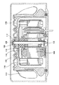
以下、本発明の好ましい実施形態を添付図面を参照して説明する。図1は、本発明の一実施形態によるファンモータの断面図である。この図1に示すように、本実施形態のファンモータ1は、ACモータであり、ファンモータ1を設置するためのベース部としてのブラケット2と、ブラケット2上に配置された回転子4および固定子6と、回転子4および固定子6を取り囲むカバー部8と、カバー部8の上側および周囲を覆うように配置されたファン部材10とを備えている。なお、本実施形態において、図1の上方をファンモータ1の上方、図1の下方をファンモータ1の下方として説明する。また、ブラケット2とカバー部8とを備えて、本発明の包囲体が構成される。
Hereinafter, preferred embodiments of the present invention will be described with reference to the accompanying drawings. FIG. 1 is a cross-sectional view of a fan motor according to an embodiment of the present invention. As shown in FIG. 1, the fan motor 1 of the present embodiment is an AC motor, and a
ブラケット2は、円盤状に形成された底面部12と、底面部12の中央部に底面部12対して垂直に立設された円筒状部14とで構成されている。底面部12の外周側には、環状の凸部16が形成されている。また円筒状部14の底部は円形の開口部14Aとなっている。
The
回転子4は、逆椀状のロータケース18と、ロータケース18の内壁に設けられたコアプレート積層体20と、回転軸22とを備えている。
ロータケース18は、円筒状の側壁の上面を円盤状部材で塞いだ有底円筒形状に形成されており、その中央部が、ブシュ24を介して回転軸22に固定されている。ロータケース18の円盤状部材の中央部には、ブシュ24の周りに円形の凹部26が形成されており、凹部26の外周壁26Aは回転軸22の周りに円筒状に、回転軸22に平行に延びている。なお、ロータケース18の凹部26は、必ずしも形成されていなくてもよい。
コアプレート積層体20は、ケイ素鋼板等からなる環状のコアプレートを複数枚積層して形成されており、その上下面には図示しない短絡リングが設けられている。コアプレート積層体20は、固定子6の外側に、固定子6の外面と平行に且つ外面から所定の隙間を有して配置されている。
The rotor 4 includes an inverted saddle-
The
The
回転軸22は、底面部12中央の円筒状部14内に配置され、固定子6の円筒状部14内面と回転軸22の外面との間には固定子側軸受28が設けられている。この固定子側軸受28によって、回転軸22は固定子6に対して回転可能に支持されている。固定子側軸受28は、ブラケット2の開口部14Aを塞ぐシール14Bによって円筒状部14内に固定されている。回転軸22の上端部は、カバー部8を貫通してカバー部8の外部に突出している。
The rotating
固定子6は、コアプレート積層体30と、コアプレート積層体30に巻き回されるコイル32とを備えている。
コアプレート積層体30は、絶縁性プラスチックからなるボビンケース上にケイ素鋼板等からなるコアプレートを複数枚積層して形成されている。コイル32は、コアプレート積層体30の周囲に連続的に巻き回されている。
固定子6の内周は、ブラケット2の円筒状部14の外周に固定されている。ここで、固定子6の内周面は、ロータケース18の凹部26の外周壁26Aよりも半径方向外側に位置する。従って、例えば図1に示されるように固定子6のボビンケース6Aがロータケース18の凹部26の底面よりも上方に突出している場合でも、固定子6がロータケース18に干渉することがない。したがって、ロータケース18内の、凹部26より上方のスペースを有効に利用することができる。
The
The
The inner periphery of the
カバー部8は、円筒状の側壁34と側壁34の上方を覆った上面36とが一体的に形成された逆椀状とされ、側壁34の下端面には、環状の凹部38が形成されている。この凹部38は、ブラケット2の凸部16に対応する位置に配置され、これらの凹部38と凸部16の間にOリング40が嵌め込まれることで、カバー部8の下端面とブラケット2の底面部12とが封止されている。また、カバー部8の上面36の中央部には、回転軸22が挿通される挿通孔42が形成されている。そして、挿通孔42の内面と回転軸22の外面との間には、カバー部側軸受44が設けられている。このカバー部側軸受44により、回転軸22は、カバー部8に対して回転可能に支持されるとともに、カバー部8と回転軸22との間の隙間が塞がれる。このような構造により、カバー部8と底面部12とで囲まれた領域は、ほぼ密閉された液密な空間46となり、この空間46に回転軸22の一部、回転子4、および固定子6が収容されている。したがって、カバー部8およびブラケット2からなる包囲体は、回転子4および固定子6の上方(上面側)、周囲(外周側)、および下方(下面側)を取り囲んでいる。
The
回転軸22には、固定子側軸受28の内輪とブシュ24との間にコイルばね45が挿通されている。コイルばね45により、固定子側軸受28およびブシュ24は、互いに離れる方向に付勢されている。これにより、コイルばね45は、固定子側軸受28の内輪と、ブシュ24を通してカバー部側軸受44の内輪とを予圧し、位置決めしている。なお、固定子側軸受28及びカバー部側軸受44への予圧は、ばねの他、ウェブワッシャーによって行ってもよい。また、コイルばね45は、固定子側軸受28及びカバー部側軸受44の外輪に設けられ、これらの軸受28,44の外輪を付勢することによって予圧する構造であってもよい。
カバー部側軸受44とファン部材10との間には、ブッシュ47が設けられており互いの間の距離が確保されている。
A
A
また、カバー部8の上面36の中央部には、挿通孔42の周りに、中心に向かって下方に傾斜する円錐台状の傾斜面48が形成されており、その上端部には、上方に突出する環状の凸部50が形成され、凸部50の外周側には、下方に凹む凹部52が形成されている。凸部50には、凸部50の外周側端部から外方に突出する板状の鍔部54が取り付けられており、この鍔部54は、凹部52の上方の一部を覆う。また、カバー部8の側壁34の外周面下端部には、外周面よりも外方で上方に突出する環状の凸部56が形成されている。なお、カバー部8上面の傾斜面48は、必ずしも設けられていなくてもよい。
In addition, a frustoconical
ファン部材10は、カバー部8の上面36(上側)および側壁34(周囲)の外方を覆うように配置され、円盤状の上面58と、上面58の外周に一体的に形成された円筒形の側壁60とを有した有底円筒形状に形成され、全体的に逆椀形状をなしている。側壁60の外周面には複数の羽根62が形成されている。ファン部材10の下端縁には、下方に開口する凹部64が形成されており、この凹部64内部にカバー部8の凸部56が突出している。また、ファン部材10の上面36の下面には、下方に突出する凸部66が形成されている。凸部66は、カバー部8の鍔部54よりも外方に位置し、凹部52内に突出する。
このような、凸部50、鍔部54、凹部52、及び凸部66の構造により、ファン部材10とカバー部8との間の隙間は、迷路状に形成され、当該隙間に液滴や埃が侵入しにくくなっている。また、ファン部材10の凹部64とカバー部8の凸部56によっても、ファン部材10とカバー部8との間の隙間が迷路状に形成され、当該隙間からファン部材10とカバー部8との間に液滴や埃が侵入するのを防止している。また、上面36の中央部には、凹部68が形成されており、この凹部68において、ファン部材10は回転軸22の上端部に固着されている。
The
With such a structure of the
上記のような構造のファンモータ1では、コイル32に電流を流して回転子4を回転させると、回転子4とともに回転軸22が回転し、ファン部材10が回転する。
In the fan motor 1 having the above structure, when a current is passed through the
このように構成された本実施形態によれば、次のような優れた効果を得ることができる。
カバー部8と回転軸22の間にカバー部側軸受44を設けて、このカバー部側軸受44により回転軸22を回転可能に支持しているので、カバー部8と回転軸22との間に隙間が生じるのを防止することができる。図2に示した従来の構造では、回転軸100は、回転子102を回転軸100に固定するブッシュ116の下方の2箇所において軸受118に支持されている。このような従来の構造では、包囲体106と回転軸100との間に隙間112が生じる。これに対して、本実施形態では、回転子4の外側において、回転軸22を支持するカバー部側軸受44を利用してカバー部8と回転軸22との間の隙間を埋めるようにしたので、カバー部8及びブラケット2で構成された包囲体で回転子6及び固定子4を液密に包囲することができ、カバー部8と回転軸22との間の隙間から液滴や埃等が侵入するのを確実に防止することができる。
According to the present embodiment configured as described above, the following excellent effects can be obtained.
Since the cover part side bearing 44 is provided between the
回転子4が固定子6の外側に配置された、所謂アウターロータ構造となっており、カバー部側軸受44がブッシュ24より上方に、且つ固定子側軸受28がブッシュ24より下方に配置されているので、回転子4を挟んで両側で回転軸22を支持することができる。したがって、回転軸22を含む回転子4の支持構造が強固となり、回転子4の回転動作を安定させることができる。
The rotor 4 has a so-called outer rotor structure in which the rotor 4 is disposed outside the
本発明は、以上の実施の形態に限定されることなく、例えば、前述の実施形態では、回転子が固定子の外側に配置されている、所謂アウターロータ構造であったが、これに限らず、固定子が回転子の外側に配置される、所謂インナーロータ構造を採用してもよい。 The present invention is not limited to the above-described embodiment. For example, in the above-described embodiment, the rotor is a so-called outer rotor structure in which the rotor is disposed outside the stator. A so-called inner rotor structure in which the stator is disposed outside the rotor may be employed.
ファンモータとしては、前述の実施形態のようなACモータに限らず、DCモータを採用してもよい。DCモータを採用する場合には、回転子としてマグネットを使用してもよく、固定子としては、前述のような積層コアを用いたものの他、粉を圧縮成形して形成される圧粉磁心材料を用いたもの、コアを用いず基板に空芯コイルを取り付けたコアレスタイプのもの等の構造を採用することができる。
また、固定子の絶縁方法としては、前述の実施形態にようにボビンケースを用いるものの他、基体に絶縁樹脂を粉体焼付塗装することにより絶縁性を確保してもよい。
The fan motor is not limited to the AC motor as in the above-described embodiment, and a DC motor may be employed. When a DC motor is employed, a magnet may be used as the rotor, and the stator is a powder magnetic core material formed by compression molding powder in addition to the one using the laminated core as described above. It is possible to adopt a structure such as a coreless type in which an air core coil is attached to a substrate without using a core.
Further, as a method for insulating the stator, in addition to using a bobbin case as in the above-described embodiment, the insulating property may be ensured by applying an insulating resin to the substrate by powder baking coating.
1 ファンモータ
2 ブラケット
4 回転子
6 固定子
8 カバー部
10 ファン部材
22 回転軸
28 固定子側軸受
42 挿通孔
DESCRIPTION OF SYMBOLS 1
Claims (2)
ブシュを介して回転軸に固定される回転子と、
前記回転軸の上端部を除いて、前記固定子及び前記回転子の全体を液密に取り囲む包囲体と、
前記回転軸の上端部に固定されたファン部材と、を有し、
前記包囲体には、前記回転軸の上端部を挿通して前記包囲体外に突出させる挿通孔が形成されており、
前記挿通孔と前記回転軸との間には包囲体側軸受が設けられ、
前記回転軸と前記固定子との間に固定子側軸受が設けられ、
前記固定子側軸受と前記ブシュとの間に予圧部材が設けられ、該予圧部材により、前記固定子側軸受の内輪又は外輪と、前記ブシュを通して前記包囲体側軸受の内輪又は外輪とが互いに離れる方向に予圧され、
前記回転子は、前記ブシュの周りに凹部を有し、前記包囲体は、前記挿通孔の周りに中央に向かって下方に傾斜する傾斜面を有し、前記ファン部材は、上面の中央部に凹部を有する、
ことを特徴とするファンモータ。 A stator,
A rotor fixed to the rotating shaft via a bush;
An enclosure that liquid-tightly surrounds the whole of the stator and the rotor except for the upper end of the rotating shaft;
A fan member fixed to the upper end of the rotating shaft,
The enclosure is formed with an insertion hole through which the upper end portion of the rotating shaft is inserted and protruded out of the enclosure.
An enclosure-side bearing is provided between the insertion hole and the rotating shaft,
A stator side bearing is provided between the rotating shaft and the stator,
A preload member is provided between the stator side bearing and the bush, and the preload member causes the inner ring or the outer ring of the stator side bearing and the inner ring or the outer ring of the enclosure side bearing to be separated from each other through the bush. Preloaded on
The rotor has a recess around the bush, the enclosure has an inclined surface inclined downward toward the center around the insertion hole, and the fan member is at the center of the upper surface. Having a recess,
A fan motor characterized by that.
請求項1に記載のファンモータ。 The rotor is disposed outside the stator;
The fan motor according to claim 1.
Priority Applications (7)
| Application Number | Priority Date | Filing Date | Title |
|---|---|---|---|
| JP2012013943A JP5884214B2 (en) | 2012-01-26 | 2012-01-26 | Fan motor |
| TW102102591A TWI536716B (en) | 2012-01-26 | 2013-01-24 | Fan motor |
| US14/122,336 US20140154108A1 (en) | 2012-01-26 | 2013-01-28 | Fan motor |
| KR1020137022918A KR101493635B1 (en) | 2012-01-26 | 2013-01-28 | Fan motor |
| DE112013000708.8T DE112013000708B4 (en) | 2012-01-26 | 2013-01-28 | blower motor |
| CN201380000614.3A CN103348570B (en) | 2012-01-26 | 2013-01-28 | Fan motor |
| PCT/JP2013/051767 WO2013111903A1 (en) | 2012-01-26 | 2013-01-28 | Fan motor |
Applications Claiming Priority (1)
| Application Number | Priority Date | Filing Date | Title |
|---|---|---|---|
| JP2012013943A JP5884214B2 (en) | 2012-01-26 | 2012-01-26 | Fan motor |
Publications (3)
| Publication Number | Publication Date |
|---|---|
| JP2013153628A JP2013153628A (en) | 2013-08-08 |
| JP2013153628A5 JP2013153628A5 (en) | 2014-10-16 |
| JP5884214B2 true JP5884214B2 (en) | 2016-03-15 |
Family
ID=48873613
Family Applications (1)
| Application Number | Title | Priority Date | Filing Date |
|---|---|---|---|
| JP2012013943A Active JP5884214B2 (en) | 2012-01-26 | 2012-01-26 | Fan motor |
Country Status (7)
| Country | Link |
|---|---|
| US (1) | US20140154108A1 (en) |
| JP (1) | JP5884214B2 (en) |
| KR (1) | KR101493635B1 (en) |
| CN (1) | CN103348570B (en) |
| DE (1) | DE112013000708B4 (en) |
| TW (1) | TWI536716B (en) |
| WO (1) | WO2013111903A1 (en) |
Families Citing this family (9)
| Publication number | Priority date | Publication date | Assignee | Title |
|---|---|---|---|---|
| JP6394444B2 (en) * | 2015-03-10 | 2018-09-26 | 株式会社デンソー | Brushless motor |
| TWI575849B (en) * | 2015-05-06 | 2017-03-21 | 佛山市建準電子有限公司 | Motor |
| US10215231B2 (en) * | 2017-06-26 | 2019-02-26 | Asia Vital Components Co., Ltd. | Bearing structure with close fit |
| KR102371384B1 (en) * | 2017-08-03 | 2022-03-07 | 엘지이노텍 주식회사 | Motor for drone |
| TWI659594B (en) * | 2018-02-09 | 2019-05-11 | 建準電機工業股份有限公司 | Bearing positioning structure and motor including the same |
| CN110932452A (en) * | 2019-12-12 | 2020-03-27 | 浙江亿雄机电制造有限公司 | Efficient and dustproof EC motor |
| KR102350767B1 (en) * | 2020-06-04 | 2022-01-14 | 주식회사 오성기전 | Brushless Direct Current Motor Assembly |
| KR102584929B1 (en) * | 2021-03-18 | 2023-10-05 | 주식회사 코아오토모티브 | Fan motor assembly |
| CN117329140B (en) * | 2023-10-17 | 2024-08-09 | 广东晟辉科技股份有限公司 | Fan blade with dustproof structure and fan |
Family Cites Families (13)
| Publication number | Priority date | Publication date | Assignee | Title |
|---|---|---|---|---|
| US4438361A (en) * | 1982-02-24 | 1984-03-20 | Imc Magnetics Corp. | Stepper motor having rotor with limited axial movement |
| JPH08182242A (en) * | 1994-12-27 | 1996-07-12 | Kosoku Denki Kk | Dustproof structure of bearing for motor |
| US5877574A (en) * | 1997-01-30 | 1999-03-02 | General Electric Company | Dynamoelectric machine |
| IT1295466B1 (en) * | 1997-10-03 | 1999-05-12 | Bitron Spa | FAN MOTOR WITH HERMETICALLY SEALED ELECTRIC MOTOR. |
| US7012346B2 (en) | 2003-03-07 | 2006-03-14 | Resmed Limited | Low profile d.c. brushless motor for an impeller mechanism or the like |
| CA2531634A1 (en) * | 2003-07-10 | 2005-01-27 | Magnetic Applications Inc. | Compact high power alternator |
| DE502005005690D1 (en) * | 2004-03-16 | 2008-11-27 | Emb Papst St Georgen Gmbh & Co | ARRANGEMENT WITH AN ELECTRONICALLY COMMUTED EXTERNAL RUNNING MOTOR |
| JP2006150571A (en) | 2004-12-01 | 2006-06-15 | Nidec Shibaura Corp | Power tool |
| JP4822021B2 (en) * | 2007-12-27 | 2011-11-24 | 株式会社育良精機製作所 | Fan motor |
| JP5198083B2 (en) * | 2008-02-05 | 2013-05-15 | ミネベアモータ株式会社 | Brushless motor |
| JP2010098816A (en) | 2008-10-15 | 2010-04-30 | Shinano Kenshi Co Ltd | Blower motor |
| GB2467966B (en) * | 2009-02-24 | 2013-04-03 | Dyson Technology Ltd | Rotor assembly |
| JP4882021B1 (en) | 2010-12-24 | 2012-02-22 | 春彦 極檀 | Heat exchange system |
-
2012
- 2012-01-26 JP JP2012013943A patent/JP5884214B2/en active Active
-
2013
- 2013-01-24 TW TW102102591A patent/TWI536716B/en active
- 2013-01-28 DE DE112013000708.8T patent/DE112013000708B4/en active Active
- 2013-01-28 WO PCT/JP2013/051767 patent/WO2013111903A1/en active Application Filing
- 2013-01-28 KR KR1020137022918A patent/KR101493635B1/en active IP Right Grant
- 2013-01-28 US US14/122,336 patent/US20140154108A1/en not_active Abandoned
- 2013-01-28 CN CN201380000614.3A patent/CN103348570B/en active Active
Also Published As
| Publication number | Publication date |
|---|---|
| CN103348570A (en) | 2013-10-09 |
| JP2013153628A (en) | 2013-08-08 |
| CN103348570B (en) | 2016-05-04 |
| TW201340555A (en) | 2013-10-01 |
| DE112013000708B4 (en) | 2022-08-18 |
| TWI536716B (en) | 2016-06-01 |
| KR20130111642A (en) | 2013-10-10 |
| WO2013111903A1 (en) | 2013-08-01 |
| DE112013000708T5 (en) | 2014-11-20 |
| US20140154108A1 (en) | 2014-06-05 |
| KR101493635B1 (en) | 2015-02-13 |
Similar Documents
| Publication | Publication Date | Title |
|---|---|---|
| JP5884214B2 (en) | Fan motor | |
| TWI532921B (en) | Electric fan | |
| JP2019112998A (en) | Air blower | |
| JP2016008579A (en) | Axial blower | |
| JP6878986B2 (en) | Stator unit, motor, and fan motor | |
| KR101840492B1 (en) | Motor for drain pump and drain pump using the same | |
| JP2017225337A (en) | motor | |
| JP2016165198A (en) | Waterproof structure for rotary machine, and rotary machine | |
| JP5402829B2 (en) | Waterproof motor | |
| JP2012186956A (en) | Brushless motor and blower fan | |
| EP3364527B1 (en) | Electric motor and blower | |
| JP5752628B2 (en) | Rotating electric machine and seal mechanism | |
| JP2017034740A (en) | Brushless motor | |
| JP2018157716A (en) | Electric motor and bearing bracket | |
| CN108933493B (en) | Motor and fan motor | |
| JP2018198521A (en) | Stator unit, motor, and fan motor | |
| JP2015142437A (en) | motor | |
| KR102335904B1 (en) | Motor | |
| JP2011035950A (en) | Waterproof structure of motor | |
| JP2020133550A (en) | Axial flow fan | |
| JP2018198503A (en) | motor | |
| JP2015050817A (en) | Brushless motor, brushless motor device, and installation method of brushless motor device | |
| JP2015220910A (en) | Magnet rotor type motor and pump including the same | |
| TWI428512B (en) | Fan | |
| KR100976953B1 (en) | spindle motor |
Legal Events
| Date | Code | Title | Description |
|---|---|---|---|
| A521 | Request for written amendment filed |
Free format text: JAPANESE INTERMEDIATE CODE: A523 Effective date: 20140827 |
|
| A621 | Written request for application examination |
Free format text: JAPANESE INTERMEDIATE CODE: A621 Effective date: 20140827 |
|
| A131 | Notification of reasons for refusal |
Free format text: JAPANESE INTERMEDIATE CODE: A131 Effective date: 20150608 |
|
| A521 | Request for written amendment filed |
Free format text: JAPANESE INTERMEDIATE CODE: A523 Effective date: 20150807 |
|
| TRDD | Decision of grant or rejection written | ||
| A01 | Written decision to grant a patent or to grant a registration (utility model) |
Free format text: JAPANESE INTERMEDIATE CODE: A01 Effective date: 20160112 |
|
| A61 | First payment of annual fees (during grant procedure) |
Free format text: JAPANESE INTERMEDIATE CODE: A61 Effective date: 20160119 |
|
| R150 | Certificate of patent or registration of utility model |
Ref document number: 5884214 Country of ref document: JP Free format text: JAPANESE INTERMEDIATE CODE: R150 |
|
| R250 | Receipt of annual fees |
Free format text: JAPANESE INTERMEDIATE CODE: R250 |
|
| R250 | Receipt of annual fees |
Free format text: JAPANESE INTERMEDIATE CODE: R250 |
|
| R250 | Receipt of annual fees |
Free format text: JAPANESE INTERMEDIATE CODE: R250 |
|
| R250 | Receipt of annual fees |
Free format text: JAPANESE INTERMEDIATE CODE: R250 |
|
| R250 | Receipt of annual fees |
Free format text: JAPANESE INTERMEDIATE CODE: R250 |
|
| R250 | Receipt of annual fees |
Free format text: JAPANESE INTERMEDIATE CODE: R250 |