JP5882886B2 - User side optical line terminator and power consumption control method for user side optical line terminator - Google Patents
User side optical line terminator and power consumption control method for user side optical line terminator Download PDFInfo
- Publication number
- JP5882886B2 JP5882886B2 JP2012282340A JP2012282340A JP5882886B2 JP 5882886 B2 JP5882886 B2 JP 5882886B2 JP 2012282340 A JP2012282340 A JP 2012282340A JP 2012282340 A JP2012282340 A JP 2012282340A JP 5882886 B2 JP5882886 B2 JP 5882886B2
- Authority
- JP
- Japan
- Prior art keywords
- interface
- frame
- state
- user
- transmission
- Prior art date
- Legal status (The legal status is an assumption and is not a legal conclusion. Google has not performed a legal analysis and makes no representation as to the accuracy of the status listed.)
- Expired - Fee Related
Links
- 230000003287 optical effect Effects 0.000 title claims description 105
- 238000000034 method Methods 0.000 title claims description 25
- 230000005540 biological transmission Effects 0.000 claims description 150
- 238000004891 communication Methods 0.000 claims description 146
- 238000011144 upstream manufacturing Methods 0.000 description 30
- 230000007704 transition Effects 0.000 description 22
- 230000008054 signal transmission Effects 0.000 description 15
- 238000012545 processing Methods 0.000 description 12
- 230000008569 process Effects 0.000 description 11
- 230000002457 bidirectional effect Effects 0.000 description 10
- 230000000694 effects Effects 0.000 description 10
- 230000001960 triggered effect Effects 0.000 description 10
- 238000010586 diagram Methods 0.000 description 9
- 238000012544 monitoring process Methods 0.000 description 8
- 239000013307 optical fiber Substances 0.000 description 7
- 230000004044 response Effects 0.000 description 7
- 238000012546 transfer Methods 0.000 description 6
- 230000002411 adverse Effects 0.000 description 2
- 238000007796 conventional method Methods 0.000 description 2
- 239000000835 fiber Substances 0.000 description 2
- 238000012986 modification Methods 0.000 description 2
- 230000004048 modification Effects 0.000 description 2
- 230000009467 reduction Effects 0.000 description 2
- 239000000725 suspension Substances 0.000 description 2
- 230000008859 change Effects 0.000 description 1
- 238000004590 computer program Methods 0.000 description 1
- 230000003111 delayed effect Effects 0.000 description 1
- 238000005516 engineering process Methods 0.000 description 1
- 238000012552 review Methods 0.000 description 1
- 238000004904 shortening Methods 0.000 description 1
- 230000011664 signaling Effects 0.000 description 1
- 230000004622 sleep time Effects 0.000 description 1
Images


Description
本発明は、ユーザ側光回線終端装置およびユーザ側光回線終端装置の消費電力制御方法に関し、特に、受動光網(PON)の局側光回線終端装置(OLT)と接続されるPONインタフェースのスリープ機能を有するユーザ側光回線終端装置およびユーザ側光回線終端装置の消費電力制御方法に関する。 The present invention relates to a user-side optical line terminator and a power consumption control method for the user-side optical line terminator, and in particular, sleep of a PON interface connected to a station-side optical line terminator (OLT) of a passive optical network (PON). The present invention relates to a user-side optical line terminator having a function and a power consumption control method for the user-side optical line terminator.
光ファイバーを伝送路として一般ユーザ宅へ直接引き込むFTTH(Fiber To The Home)サービスを提供する光アクセスシステムとして、受動光網(PON:Passive Optical Network。以下、単に「PON」という。)システムがある。PONシステムは、局側光回線終端装置(OLT:Optical Line Terminal。以下、単に「OLT」という。)と複数のユーザ側光回線終端装置(ONU:Optical Network Unit。以下、単に「ONU」という。)が、光ファイバおよび光分岐結合器を介してポイント・ツー・マルチポイントの接続形態によって接続された光アクセス網である。 As an optical access system that provides an FTTH (Fiber To The Home) service that directly draws an optical fiber into a general user's home as a transmission path, there is a passive optical network (PON: simply referred to as “PON” hereinafter) system. The PON system includes a station side optical line terminator (OLT: Optical Line Terminal; hereinafter simply referred to as “OLT”) and a plurality of user side optical line terminators (ONU: Optical Network Unit), hereinafter simply referred to as “ONU”. ) Is an optical access network connected by a point-to-multipoint topology through an optical fiber and an optical branching coupler.
PONシステムでは、局側からユーザ側に送られる下り信号としてOLTが送信した光信号は、光分岐結合器によって分岐され、全ONUに同一の下り信号がブロードキャスト方式で送信される。各ONUは、受信した光信号を光電変換するとともに、受信したフレームに含まれたロジカルリンク識別子(LLID:Logical Link ID)に基づいて、その受信フレームが自分宛(配下のユーザ機器を含む。)であるかどうかを判断し、受信フレームの取捨選択を行っている。 In the PON system, an optical signal transmitted by the OLT as a downlink signal sent from the station side to the user side is branched by an optical branching coupler, and the same downlink signal is transmitted to all ONUs by a broadcast method. Each ONU photoelectrically converts the received optical signal, and the received frame is addressed to itself (including subordinate user equipment) based on a logical link identifier (LLID) included in the received frame. Whether the received frame is selected or not is selected.
一方、ユーザ側から局側に送られる上り信号として各ONUが送信した各光信号は、光分岐結合器によって結合され、OLTで受信される。このとき、異なるONUが送出した各光信号が衝突すること(あるONUからの光信号と別のONUの光信号が共通の光ファイバ中を重なって伝送されることによってOLTが各ONUからの信号を分離して受信できない状態となること)を避けるため、PONシステムでは、OLTは、各ONUが送信可能な時刻と期間を通知するGATE信号を各ONUに送信し、各ONUは、受信したGATE信号によって指定された時刻と期間に光信号をOLTに向けて送信する、いわゆる時分割多元接続(TDMA:Time Division Multiple Access)制御が行われる。 On the other hand, each optical signal transmitted from each ONU as an upstream signal transmitted from the user side to the station side is combined by an optical branching coupler and received by the OLT. At this time, the optical signals transmitted from different ONUs collide (the optical signal from one ONU and the optical signal of another ONU are transmitted through a common optical fiber so that the OLT receives a signal from each ONU. In the PON system, the OLT transmits a GATE signal notifying each ONU of a time and period during which each ONU can transmit, and each ONU receives the received GATE. So-called time division multiple access (TDMA) control is performed in which an optical signal is transmitted to the OLT at a time and a period specified by the signal.
下り信号(OLTからONU)と上り信号(ONUからOLT)とは、波長多重により、すなわちそれぞれ異なる波長の光信号を用いて、双方向に通信される。 The downstream signal (OLT to ONU) and the upstream signal (ONU to OLT) are bidirectionally communicated by wavelength multiplexing, that is, using optical signals of different wavelengths.
従来より、PONシステムにおける高速・低消費電力化にむけた様々な取り組みがなされている。その中でもONUの消費電力を削減する方法として、イーサネット(登録商標)等のLANを介して接続されるユーザ側通信装置との通信を一時停止する等して、その通信機能を制限する「LAN低電力制御」と、ONUとOLTの間の通信を一時停止させる等して、その通信機能を制限する「PONスリープ制御」がある。 Conventionally, various efforts have been made for high speed and low power consumption in the PON system. Among them, as a method for reducing the power consumption of the ONU, “LAN low” that restricts the communication function by temporarily suspending communication with a user side communication device connected via a LAN such as Ethernet (registered trademark). There are “power control” and “PON sleep control” that limits the communication function by temporarily stopping communication between the ONU and the OLT.
このうち、LAN低電力制御は、ONUがユーザ側通信装置とLAN等のユーザネットワークを介して接続するためのONUのインタフェースであるLANインタフェースの機能の一部を一時停止することによって、LANインタフェースの消費電力を低減するものである。ユーザ側通信装置とONUとの接続に用いられるLANには、IEEE 802.3で標準化されたプロトコルが採用されている。また、LANに接続するためのインタフェース回路を省電力化するために、IEEE 802.3azとして標準化されたLAN低電力制御がある。 Among these, the LAN low power control is performed by temporarily suspending a part of the function of the LAN interface, which is an ONU interface for the ONU to connect to the user side communication device via the user network such as the LAN. The power consumption is reduced. A protocol standardized by IEEE 802.3 is adopted for a LAN used for connection between a user-side communication device and an ONU. In addition, there is a LAN low power control standardized as IEEE 802.3az in order to save power in an interface circuit for connecting to a LAN.
一方、PONスリープ制御は、OLTとONUとの間で通信が行われていないときには、OLTとの通信の少なくとも一部を一時停止させる「スリープモード」に移行するものである。スリープモードには、ONUからOLTへの上り方向の通信を一時停止させるがOLTからONUへの下り方向の通信を停止させない「上り方向スリープモード」と、両方向の通信を一時停止させる「双方向スリープモード」とがある。いずれのモードにおいても、ONUとOLTとの間の通信の発生を間欠的なものにしたり、通信速度を低下させたりすることによって、ONUがOLTに接続するONUのインタフェースであるPONインタフェースに関わる消費電力を低減することができる(例えば、非特許文献1、および非特許文献2)。
On the other hand, the PON sleep control shifts to a “sleep mode” in which at least a part of communication with the OLT is temporarily stopped when communication between the OLT and the ONU is not performed. The sleep mode includes an “uplink sleep mode” that temporarily stops upstream communication from the ONU to the OLT but does not stop downstream communication from the OLT to the ONU, and a “bidirectional sleep” that temporarily stops communication in both directions. Mode ". In any mode, the ONU consumes the PON interface, which is the interface of the ONU that connects to the OLT, by intermittently generating communication between the ONU and the OLT or reducing the communication speed. Electric power can be reduced (for example, Non-Patent
このように、ONUの消費電力削減には、LANインタフェースに対するLAN低電力制御とPONインタフェースに対するPONスリープ制御という、2種類の制御方法を採用することが可能である。 As described above, to reduce the power consumption of the ONU, it is possible to adopt two types of control methods, that is, the LAN low power control for the LAN interface and the PON sleep control for the PON interface.
ところで、上述したPONスリープ制御においては、通信の一時停止による通信アプリケーションへの悪影響を避けるため、OLTとのすべての通信機能が稼働する通常モードからスリープモードへ移行は、ONUやOLTが通信量監視を行い、通信が一定期間(時間Ti)行われていないことを契機として行い、スリープモードから通常モードへの復帰は、ONUがOLTへ送信すべきフレームをユーザ側通信装置から受信すること、または、OLTがONUを介してユーザ側通信装置へ送信すべきフレームをOLTの上流側装置から受信したことを契機として行っている。 By the way, in the above-described PON sleep control, in order to avoid the adverse effect on the communication application due to the temporary suspension of communication, the transition from the normal mode in which all communication functions with the OLT are operated to the sleep mode is performed by the ONU and the OLT. And when the communication is not performed for a certain period (time Ti), the return from the sleep mode to the normal mode is that the ONU receives a frame to be transmitted to the OLT from the user side communication device, or The OLT receives a frame to be transmitted to the user side communication apparatus via the ONU from the upstream apparatus of the OLT.
このようにPONスリープ制御においては、一定の時間Ti中に通信が行われなかったときにスリープモードに移行するので、ユーザ側通信装置が通信を停止してからスリープモードに移行するまでに時間Ti以上の遅れが生じ、スリープモードの期間が短縮されることで、消費電力低減の効果が下がるという問題があった。 As described above, in the PON sleep control, when communication is not performed during a certain time Ti, the mode is shifted to the sleep mode. Therefore, the time Ti from when the user-side communication apparatus stops communication until the mode shifts to the sleep mode. There has been a problem that the effect of reducing power consumption is reduced due to the above delay and the shortening of the sleep mode period.
そこで、本発明は、ユーザ側通信装置が通信を停止してからスリープモードに移行するまでの時間を短縮し、PONインタフェースのスリープ制御によるONUの消費電力削減効果を向上させることを目的とする。 Therefore, an object of the present invention is to shorten the time from when the user-side communication device stops communication until it shifts to the sleep mode, and to improve the ONU power consumption reduction effect by the sleep control of the PON interface.
上述した目的を達成するために、本発明に係るユーザ側光回線終端装置(ONU)は、例えば、ユーザネットワークを介してユーザ側通信装置と接続される第1のインタフェースと、受動光網(PON)を介して局側光回線終端装置(OLT)と接続される第2のインタフェースとを備え、前記第1のインタフェースは、前記ユーザ側通信装置からフレームを受信するとともに、前記第2のインタフェースが前記局側光終端装置から受信したフレームの少なくとも一部を前記ユーザ側通信装置に送信する第1の送受信部と、前記ユーザ側通信装置がフレームを送信または受信する機能を制限してフレームの送受信に関わる消費電力を低減する低電力送受信状態にあることを示すスリープ信号を前記第1のインタフェースが受信すると、前記第1の送受信部のフレームを送信または受信する機能を制限して、前記第1のインタフェースを、前記第1のインタフェースの消費電力を低減可能な低電力送受信状態とする第1の状態制御部とを備え、前記第2のインタフェースは、光信号と電気信号とを相互に変換して、前記局側光終端装置からフレームを受信するとともに、前記第1のインタフェースが前記ユーザ側通信装置から受信したフレームの少なくとも一部を前記局側光回線終端装置に送信する第2の送受信部と、前記第1のインタフェースが前記スリープ信号を受信したことまたは前記低電力送受信状態となったことを契機として、前記第2の送受信部のフレームを送信または送受信する機能を制限して、前記第2のインタフェースを、前記第2のインタフェースの消費電力を低減可能なスリープ状態とする第2の状態制御部とを備えたことを特徴とする。 In order to achieve the above-described object, a user-side optical network unit (ONU) according to the present invention includes, for example, a first interface connected to a user-side communication device via a user network, and a passive optical network (PON). ) Through a second interface connected to a station side optical line termination device (OLT) through the network, the first interface receives a frame from the user side communication device, and the second interface A first transmission / reception unit for transmitting at least a part of a frame received from the station-side optical terminal to the user-side communication device; When the first interface receives a sleep signal indicating a low power transmission / reception state that reduces power consumption related to A first state control unit that limits a function of transmitting or receiving a frame of the first transmission / reception unit and sets the first interface to a low power transmission / reception state that can reduce power consumption of the first interface. The second interface converts an optical signal and an electrical signal to each other, receives a frame from the station-side optical termination device, and receives a frame received from the user-side communication device by the first interface. Triggered by the second transmitting / receiving unit transmitting at least a part to the station side optical line terminating device and the first interface receiving the sleep signal or entering the low power transmitting / receiving state. also transmits the second transmission and reception of the frame by limiting the ability to send and receive, the second interface, the power consumption of the second interface It characterized in that a second state controller to decrease possible sleep.
また、本発明に係るユーザ側光回線終端装置(ONU)の消費電力制御方法は、ユーザネットワークを介してユーザ側通信装置と接続される第1のインタフェースと、受動光網(PON)を介して局側光回線終端装置(OLT)と接続される第2のインタフェースと、前記局側光終端装置(OLT)に送信するフレームを保留するバッファとを備え、前記第1のインタフェースが前記ユーザ側通信装置から受信したフレームの少なくとも一部を前記第2のインタフェースから前記局側光回線終端装置に送信し、前記第2のインタフェースが前記局側光終端装置から受信したフレームの少なくとも一部を前記第1のインタフェースから前記ユーザ側通信装置に送信するユーザ側光回線終端装置(ONU)の消費電力制御方法において、前記ユーザ側通信装置がフレームを送信または受信する機能を制限してフレームの送信または受信に関わる消費電力を低減する低電力送受信状態にあることを示すスリープ信号を前記第1のインタフェースが受信するステップと、前記スリープ信号を受信した前記第1のインタフェースが、前記ユーザ側通信装置とフレームを送信または受信する機能を制限しない通常送受信状態から、フレームを送信または受信する機能を制限して、前記第1のインタフェースの消費電力を低減可能な低電力送受信状態とするステップと、前記第1のインタフェースが前記スリープ信号を受信したことまたは前記低電力送受信状態となったことを契機として、前記第2の送受信部のフレームを送信または送受信する機能を制限して、前記第2のインタフェースを、前記第2のインタフェースの消費電力を低減可能なスリープ状態とするステップとを有し、前記第2のインタフェースを前記スリープ状態とするステップは、前記第1のインタフェースが前記低電力送受信状態となり、かつ、前記バッファに保留されたフレームの量が所定の値以下となった後に、前記第2のインタフェースを前記スリープ状態とすることを特徴とする。 In addition, a power consumption control method for a user-side optical network unit (ONU) according to the present invention includes a first interface connected to a user-side communication device via a user network and a passive optical network (PON). A second interface connected to a station-side optical line termination device (OLT); and a buffer for holding a frame to be transmitted to the station-side optical termination device (OLT) , wherein the first interface communicates with the user-side communication Transmitting at least a part of the frame received from the apparatus from the second interface to the station-side optical terminal unit, and transmitting at least a part of the frame received from the station-side optical terminal unit by the second interface In the power consumption control method of a user side optical network unit (ONU) that transmits to the user side communication device from one interface, the user The first interface receives a sleep signal indicating that the communication device is in a low power transmission / reception state that limits a function of transmitting or receiving a frame to reduce power consumption related to frame transmission or reception; The first interface that has received the sleep signal restricts the function of transmitting or receiving a frame from the normal transmission / reception state in which the function of transmitting or receiving a frame with the user-side communication device is not restricted, and the first interface The second transmission / reception unit triggered by the step of setting a low power transmission / reception state capable of reducing power consumption of the interface, and when the first interface has received the sleep signal or has entered the low power transmission / reception state The function of transmitting or transmitting / receiving frames is limited, and the second interface is Possess a step of the reduction can sleep power consumption of the second interface, the step of the second interface with the sleep state, the first interface is between the low power transceiver state and The second interface is set in the sleep state after the amount of frames held in the buffer becomes equal to or less than a predetermined value.
ここで、本発明においては、前記ユーザ側光回線終端装置(ONU)は、さらに前記局側光終端装置(OLT)に送信するフレームを保留するバッファを備え、前記第2の状態制御部は、前記第1のインタフェースが前記低電力送受信状態となり、かつ、前記バッファに保留されたフレームの量が所定の値以下となった後に、前記第2のインタフェースを前記スリープ状態とするように構成してもよい。 Here, in the present invention, the user side optical network unit (ONU) further includes a buffer for holding a frame to be transmitted to the station side optical unit (OLT), and the second state control unit includes: the first interface becomes a pre SL low power transceiver state, and, after the amount of frames that are held in the buffer is equal to or less than a predetermined value, it constitutes the second interface to said sleep state May be.
また、本発明において、前記第1の状態制御部は、さらに、前記低電力送受信状態にある前記第1のインタフェースが、前記ユーザ側通信装置が前記低電力送受信状態からフレームを送信または受信する機能を制限しない通常送受信状態となることを示すアイドル信号を受信すると、前記第1のインタフェースを、前記低電力送受信状態から前記第1の送受信部が前記ユーザ側通信装置とフレームを送信または受信する機能を制限しない通常送受信状態とし、前記第2の状態制御部は、前記第1のインタフェースが前記アイドル信号を受信したことまたは前記低電力送受信状態から前記通常送受信状態となったことを契機として、前記第2のインタフェースを前記スリープ状態から前記第2の送受信部がフレームを送信または送受信する機能を制限しない通常送受信状態とするように構成してもよい。 In the present invention, the first state control unit further includes a function in which the first interface in the low power transmission / reception state transmits or receives a frame from the low power transmission / reception state by the user side communication device. When receiving an idle signal indicating that a normal transmission / reception state without restriction is received, the first interface transmits / receives a frame to / from the user side communication device from the low power transmission / reception state. The second state control unit is triggered by the fact that the first interface has received the idle signal or has entered the normal transmission / reception state from the low power transmission / reception state. Function for transmitting or transmitting / receiving a frame from / to the sleep state of the second interface by the second transmission / reception unit Usually it may be configured so as to transmit and receive state of not limiting.
また、本発明に係るユーザ側光回線終端装置(ONU)は、ユーザネットワークを介してユーザ側通信装置と接続されて、前記ユーザ側通信装置とフレームを送受信するとともに、前記ユーザ側通信装置がフレームを送信または受信する機能を制限してフレームの送受信に関わる消費電力を低減する低電力送受信状態にあることを示すスリープ信号を受信すると、フレームを送信または受信する機能を制限して消費電力を低減可能な低電力送受信状態となる第1のインタフェースと、受動光網を介して局側光回線終端装置と接続されて、光信号と電気信号とを相互に変換して前記局側光終端装置とフレームを送受信するとともに、フレームを送信または送受信する機能を制限して消費電力を低減可能なスリープ状態となることができる第2のインタフェースとを備え、前記第1のインタフェースは、前記ユーザ側通信装置からフレームを受信するとともに、前記第2のインタフェースが前記局側光終端装置から受信したフレームの少なくとも一部を前記ユーザ側通信装置に送信する第1の送受信部と、フレームを送信または受信する機能を制限して消費電力を低減可能な低電力送受信状態にある前記第1のインタフェースが、前記ユーザ側通信装置がフレームを送信または受信する機能を制限してフレームの送受信に関わる消費電力を低減する低電力送受信状態からフレームを送信または受信する機能を制限しない通常送受信状態となることを示すアイドル信号を受信すると、前記第1のインタフェースを、前記低電力送受信状態から前記第1の送受信部が前記ユーザ側通信装置とフレームを送信または受信する機能を制限しない通常送受信状態とする第1の状態制御部とを備え、前記第2のインタフェースは、光信号と電気信号とを相互に変換して、前記局側光終端装置からフレームを受信するとともに、前記第1のインタフェースが前記ユーザ側通信装置から受信したフレームの少なくとも一部を前記局側光回線終端装置に送信する第2の送受信部と、前記第1のインタフェースが前記アイドル信号を受信したことまたは前記低電力送受信状態から前記通常送受信状態となったことを契機として、前記第2のインタフェースを前記スリープ状態から前記第2の送受信部がフレームを送信または送受信する機能を制限しない通常送受信状態とする第2の状態制御部とを備えたことを特徴とする。 In addition, a user-side optical network unit (ONU) according to the present invention is connected to a user-side communication device via a user network and transmits / receives a frame to / from the user-side communication device. Reduces power consumption by restricting the function to transmit or receive frames, and reducing the power consumption related to frame transmission / reception When receiving a sleep signal indicating that it is in a low power transmission / reception state, it limits the function to transmit or receive frames A first interface that is in a possible low power transmission / reception state, and is connected to a station side optical line terminator through a passive optical network, and converts the optical signal and the electrical signal to each other, A second state in which a frame can be transmitted and received, and a sleep state in which power consumption can be reduced by limiting a function of transmitting or transmitting a frame. And the first interface receives a frame from the user side communication device, and at least a part of the frame received by the second interface from the station side optical terminal device is the user side communication device. The first interface in a low power transmission / reception state capable of reducing power consumption by limiting the function of transmitting or receiving frames, and the user side communication device transmits frames. When receiving an idle signal indicating that a normal transmission / reception state in which a function of transmitting or receiving a frame is not restricted is received from a low-power transmission / reception state in which the function to receive is limited to reduce power consumption related to frame transmission / reception, the first An interface is connected to the user side communication device from the low power transmission / reception state by the first transmission / reception unit. A first state control unit that sets a normal transmission / reception state that does not restrict a function of transmitting or receiving a frame, and the second interface converts an optical signal and an electrical signal to each other, and A second transmission / reception unit for receiving a frame from a device and transmitting at least part of the frame received by the first interface from the user-side communication device to the station-side optical network unit; and the first interface Triggered by the reception of the idle signal or the transition from the low power transmission / reception state to the normal transmission / reception state, the second transmission / reception unit transmits or transmits a frame from the sleep state to the second interface. And a second state control unit configured to perform a normal transmission / reception state without limiting functions.
本発明によれば、ユーザ側通信装置がフレームを送信または受信する機能を制限してフレームの送信に関わる消費電力を低減する低電力送受信状態にあることがスリープ信号により第1のインタフェースに通知されると、第1のインタフェースを低電力送受信状態とするとともに、これを契機として、受動光網(PON)に接続された第2のインタフェースをスリープ状態とする。したがって、第1のインタフェースが低電力送受信状態となった後は、第2のインタフェースをスリープ状態にするために、時間Tiの間、通信を監視する必要がないので、第2のインタフェースがスリープ状態となるまでの時間を短縮することができ、ひいては、第2のインタフェースのスリープ制御によるONUの消費電力の削減効果を向上させることができる。 According to the present invention, the first interface is notified by the sleep signal that the user-side communication device is in a low power transmission / reception state in which the function of transmitting or receiving frames is limited to reduce power consumption related to frame transmission. Then, the first interface is set to the low power transmission / reception state, and the second interface connected to the passive optical network (PON) is set to the sleep state in response to this. Therefore, after the first interface enters the low power transmission / reception state, there is no need to monitor communication during the time Ti in order to put the second interface into the sleep state, so the second interface is in the sleep state. Can be shortened, and as a result, the effect of reducing the power consumption of the ONU by the sleep control of the second interface can be improved.
以下、本発明の実施の形態について、図面を参照しながら説明する。 Hereinafter, embodiments of the present invention will be described with reference to the drawings.
[PONシステム]
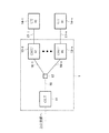
図1は、受動光網システム(以下、「PONシステム」という。)1に含まれる複数のユーザ側光回線終端装置(以下、「ONU」という。)13−1〜13−n(ただし、nは整数。)に、それぞれユーザネットワーク17−1〜17−nを介してユーザ通信装置(UT:User Terminal)14−1〜14−nが接続されている構成を示している。
[PON system]
FIG. 1 shows a plurality of user-side optical line terminators (hereinafter referred to as “ONUs”) 13-1 to 13 -n (hereinafter, n) included in a passive optical network system (hereinafter referred to as “PON system”) 1. Is an integer.), User communication devices (UT: User Terminal) 14-1 to 14-n are connected via user networks 17-1 to 17-n, respectively.
ここでPONシステム1は、図1に示すように、サービス網を構成する上位装置(図示せず)と接続された局側光回線終端装置(以下、「OLT」という。)11と、複数のONU13−1〜31−nとが、光ファイバ15,16および光分岐結合器12を介してポイント・ツー・マルチポイントの接続形態によって接続されている。
Here, as shown in FIG. 1, the
このようなPONシステム1において、OLT11が送信した光信号は、光分岐結合器12によって分岐され、各ONU13−1〜13−nで受信される。また、各ONU13−1〜13−nが送信した各光信号は、光分岐結合器12によって結合され、OLT11で受信される。
PONシステム1では、複数の異なるONU13−1〜13−nが送出した各光信号が衝突する(あるONUからの光信号と別のONUの光信号が共通の光ファイバ中を重なって伝送されることによってOLTが各ONUからの信号を分離して受信できない状態となる)ことを避けるため、OLT11は、各ONU13−1〜13−nにGATE信号を送信して、各ONU13−1〜13−nが光信号を送信可能な時刻と期間を通知する。各ONU13−1〜13−nが、受信したGATE信号に基づいて光信号をOLT11に向けて送信することによって、時分割多元接続(TDMA)制御が行われる。
In such a
In the
一方、各ONU13−1〜13−nとユーザ側通信装置機器14−1〜14−nとを接続するユーザネットワーク17−1〜17−nは、例えば、イーサネット(登録商標)等の信号で接続されたローカル・エリア・ネットワーク(LAN:Local Area Network。以下、「LAN」という。)である。また、ユーザ通信機器17−1〜17−nは、例えば、ユーザのパーソナルコンピュータ(PC)やIP電話端末などの他、1個以上の宅内通信端末が接続されたホームゲートウェイが考えられる。 On the other hand, the user networks 17-1 to 17-n that connect the respective ONUs 13-1 to 13-n and the user side communication device devices 14-1 to 14-n are connected by signals such as Ethernet (registered trademark), for example. A local area network (LAN: Local Area Network; hereinafter referred to as “LAN”). The user communication devices 17-1 to 17-n may be home gateways to which one or more home communication terminals are connected in addition to the user's personal computer (PC), IP phone terminal, and the like.
[ONUの構成]
次に、本実施の形態に係るONUについて、上述したPONシステム1を構成する複数のONU13−1〜13−nのうちのONU13−nを例に説明する。以下、ONU13−nを「ONU #n」ということがある。
[Configuration of ONU]
Next, the ONU according to the present embodiment will be described using the ONU 13-n among the plurality of ONUs 13-1 to 13-n configuring the
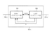
ONU #nは、図2に示すように、ONU #nを光ファイバ16−nを介してOLT11に接続するためのインタフェースであるPONインタフェース部131と、ONU #nをユーザ通信装置14−nにLAN17−nを介して接続するためのインタフェースであるLANインタフェース部132を備えている。
As shown in FIG. 2, the ONU #n sends the ONU #n to the
PONインタフェース部131は、OLT11が送信した下りフレームのうちONU #n宛てのフレームを受信して、PONインタフェースに従ったMAC処理を行った後、LANインタフェース部132に出力する。また、LANインタフェース部132から出力された上りフレームをPONインタフェースに沿った処理を行って送信する。
The
一方、LANインタフェース部132は、ユーザ側通信装置14−nが送信した上りフレームを受信してLANインタフェースに従ったMAC処理やブリッジ処理を行ったのち、PONインタフェース部131に出力する。また、LANインタフェース部132は、PONインタフェース部131から出力された下りフレームにブリッジ処理やLANインタフェースに従ったMAC処理を行った後、ユーザ側通信装置14−nに送信する。
On the other hand, the
ユーザ側通信装置14−nは、LANインタフェースを備え、ONU #nとLANを介して接続される。ユーザ側通信装置14−nがLANインタフェースから送信したフレームはLAN17−nを介してONU #nのLANインタフェース部132へと転送される。さらに、このフレームは、ONU #nのPONインタフェース131から送出され、PONを介して、OLT11のPONインタフェースへと転送され、さらには、OLT11の上流側装置へと転送される。
The user-side communication device 14-n includes a LAN interface and is connected to the ONU #n via the LAN. A frame transmitted from the LAN interface by the user side communication device 14-n is transferred to the
また、OLTの上流側装置からOLTに転送されたフレームは、OLTのPONインタフェースから送出され、PONを介して、ONUのPONインタフェースへと転送される。さらに、前記フレームは、ONUのLANインタフェースから送出され、LANを介して、ユーザ側通信装置のLANインタフェースへと転送され、前記ユーザ側通信装置において受信される。 A frame transferred from the upstream device of the OLT to the OLT is transmitted from the PON interface of the OLT and transferred to the PON interface of the ONU via the PON. Further, the frame is transmitted from the LAN interface of the ONU, transferred to the LAN interface of the user side communication device via the LAN, and received by the user side communication device.
上述したPONシステム1において、ONU #nの消費電力を削減するために、ONU #nとOLT11との間の通信を制限する「PONスリープ制御」を採用する。このPONスリープ制御では、通信を一時停止させる「スリープモード」に移行することによって、ONU #nがOLT11に接続するONUのインタフェースであるPONインタフェースに関わる、消費電力を低減することができる。前記スリープモードには、ONUからOLTへの上り方向の通信を一時停止させるがOLTからONUへの下り方向の通信を停止させない「上り方向スリープモード」と、両方向の通信を一時停止させる「双方向スリープモード」がある。
In the
また、PONインタフェース部131は、PONスリープ制御を行うための信号をOLT11との間で送受信するとともに、PONスリープ制御に関わる状態遷移を管理し、その状態に基づいてPONインタフェース部131内の回路での消費電力を低減する。
The
一方、LANインタフェース部132は、LAN低電力制御を行うための信号をユーザ側通信装置14−nとの間で送受信するとともに、LAN低電力制御に関わる状態遷移を管理し、その状態に基づいてLANインタフェース部132内の回路での消費電力を低減する。より具体的には、ONU #nとユーザ側通信装置14−nの各LANインタフェースに関わる回路を省電力化するために、IEEE 802.3azとして標準化されたLAN低電力制御を採用する。低電力モードへの移行によって、LANインタフェースに関わる、消費電力を低減することができる。
On the other hand, the
本実施の形態に係るONU #nでは、さらに、LANインタフェース部132は、LAN低電力制御によってLANインタフェースが、フレームを受信する機能を停止しない通常受信状態から低電力受信状態に移行したこと、または、LANインタフェースが通常受信状態においてユーザ側通信装置14−nからのスリープ信号を受信したことを、LANスリープ通知信号aによってPONインタフェース部131に通知する。
In the ONU #n according to the present embodiment, the
本実施の形態に係るONU #nにおいて、PONインタフェース部131は、LANインタフェース部132が出力したLANスリープ通知信号aが入力されると、この信号に基づいて、通常状態からスリープ要求信号送信待ち状態に移行し、さらに、上り方向スリープ要求信号の送信によって上り方向スリープ状態へと移行するか、双方向スリープ要求信号の送信によって双方向スリープ状態へと移行する。
In the ONU #n according to the present embodiment, when the LAN sleep notification signal a output from the
また、LANインタフェース部132は、LAN低電力制御によってLANインタフェースが低電力受信状態から通常受信状態に移行したこと、または、LANインタフェースが低電力受信状態においてユーザ側通信装置からのアイドル信号を受信したことを、LANウェイクアップ通知信号bによってPONインタフェース部131に通知する。
In addition, the
PONインタフェース部131は、LANインタフェース部132が出力するLANウェイクアップ通知信号bが入力されると、ONU #nのPONインタフェースは、上り方向スリープ状態あるいは双方向スリープ状態から、ウェイクアップ要求信号送信待ち状態に移行し、さらに、ウェイクアップ要求信号の送信によって通常状態へと移行する。
When the LAN wakeup notification signal b output from the
図3は、上述したONUの一構成例を示す機能ブロック図である。
ONUがフレームを受け取り転送する機能に関わるものとしては、上位装置に近い方から、PON区間の光信号とONU内の電気信号を変換する光送受信部(TRx送受信部)1212、MPCP(Multipoint Control Protocol)制御フレームの送受信処理や同期処理を行うPON信号処理部1313、MAC(Media Access Control)処理やブリッジ処理を行うBRG部133、下り方向フレームおよび上り方向フレームをそれぞれ一時蓄積したり、フレーム蓄積量を算出するバッファ134、135、ユーザネットワーク(LAN)とのインタフェースとなるUNI(User Network Interface)1322等を備えている。
FIG. 3 is a functional block diagram illustrating a configuration example of the ONU described above.
The ONU is related to the function of receiving and transferring frames, from the side closer to the host device, the optical transmission / reception unit (TRx transmission / reception unit) 1212 that converts the optical signal in the PON section and the electrical signal in the ONU, MPCP (Multipoint Control Protocol). ) PON
また、上述したPONインタフェース部131のPONスリープ制御に関わる状態遷移を管理し制御する状態制御部1311、およびLANインタフェース部132のLAN低電力制御に関わる状態遷移を管理し制御する状態制御部1321を備えている。
Further, a
この実施の形態においては、LANインタフェース部132は、本発明におけるユーザネットワークを介してユーザ側通信装置と接続される「第1のインタフェース」に相当し、PONインタフェース部131は、PONを介してOLTと接続される「第2のインタフェース」に相当する。
また、LANインタフェース部132を構成するUNI部1322は、本発明におけるユーザ側通信装置からフレームを受信するとともに、第2のインタフェース(PONインタフェース部131)がOLTから受信したフレームの少なくとも一部を前記ユーザ側通信装置に送信する「第1の送受信部」に相当する。
In this embodiment, the
The
また、ユーザ側通信装置がフレームを送信する機能を制限してフレームの送信に関わる消費電力を低減する低電力送受信状態にあることを示すスリープ信号を第1のインタフェース(LANインタフェース部132)が受信すると、第1の送受信部(UNI部1322)のフレームを受信する機能を一時停止して、第1のインタフェース(LANインタフェース部132)を、第1のインタフェースの消費電力を低減可能な低電力受信状態(LAN低電力受信状態)とする「第1の状態制御部」に相当する。 In addition, the first interface (LAN interface unit 132) receives a sleep signal indicating that the user side communication device is in a low power transmission / reception state that limits the function of transmitting a frame to reduce power consumption related to frame transmission. Then, the function of receiving the frame of the first transmission / reception unit (UNI unit 1322) is temporarily stopped, and the first interface (LAN interface unit 132) can receive the low power to reduce the power consumption of the first interface. This corresponds to a “first state control unit” that is in a state (LAN low power reception state).
また、PONインタフェース部131を構成する光送受信部1312は、光信号と電気信号とを相互に変換して、OTLからフレームを受信するとともに、第1のインタフェース(LANインタフェース部132)がユーザ側通信装置から受信したフレームの少なくとも一部をOLTに送信する「第2の送受信部」に相当し、状態制御部1311は、第1のインタフェース(LANインタフェース部132)がスリープ信号を受信したことまたは低電力受信状態となったことを契機として、第2の送受信部(光送受信部1312)のフレームを送信する機能を停止して、第2のインタフェース(PONインタフェース部131)を、第2のインタフェースの消費電力を低減可能なスリープ状態とする「第2の状態制御部」に相当する。
The optical transmission /
なお、本実施の形態に係るONUは、後述するように、第1のインタフェース(LANインタフェース部132)がスリープ信号を受信したことまたは低電力受信状態となったことを契機として、第2のインタフェース(PONインタフェース部131)を、第2のインタフェースの消費電力を低減可能なスリープ状態とする他、従来のONUと同様に、OLTからの指示に基づいて、または、ONU自身が上り若しくは下りの少なくとも一方のトラフィックを監視することによって、PONインタフェース部131およびLANインタフェース部132をそれぞれスリープ状態および低電力送受信状態に移行させることもできる。
Note that the ONU according to the present embodiment, as will be described later, is triggered by the fact that the first interface (LAN interface unit 132) receives a sleep signal or enters a low power reception state. (PON interface unit 131) is set to a sleep state in which the power consumption of the second interface can be reduced, and in the same way as a conventional ONU, based on an instruction from the OLT, or the ONU itself is at least up or down. By monitoring one of the traffics, the
上述した各種機能部による処理は、記憶装置を備えた演算装置(CPU:Central Process Unit)とコンピュータプログラムとが協働することによって実現される。 The processing by the various functional units described above is realized by the cooperation of an arithmetic device (CPU: Central Process Unit) including a storage device and a computer program.
なお、LANスリープ通知信号とLANウェイクアップ通知信号とを1本のLANウェイクアップ・スリープ通知信号として実装することも可能であり、この場合は、前記LANウェイクアップ・スリープ通知信号の値が0から1に変化する時点をLANウェイクアップ通知信号として使用し、前記LANウェイクアップ・スリープ通知信号の値が1から0に変化する時点をLANスリープ通知信号として使用することができる。
また、PONインタフェース部131がPONスリープ制御を内部のCPU上で動作するソフトウェアとして実装する場合には、LANウェイクアップ通知信号とLANスリープ通知信号を前記CPUへの割り込み信号線として実装することも可能である。
Note that the LAN sleep notification signal and the LAN wake-up notification signal can be implemented as a single LAN wake-up / sleep notification signal. In this case, the value of the LAN wake-up / sleep notification signal is 0. The time point when the value changes to 1 can be used as the LAN wakeup notification signal, and the time point when the value of the LAN wakeup / sleep notification signal changes from 1 to 0 can be used as the LAN sleep notification signal.
In addition, when the
[ONUの動作]
次に、本実施の形態に係るONU #nの動作について、図4および図5を参照して説明する。
[Operation of ONU]
Next, the operation of ONU #n according to the present embodiment will be described with reference to FIG. 4 and FIG.
[通常モードからスリープモードへの移行シーケンス]
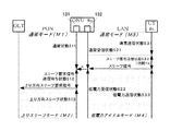
図4は、ユーザ側通信装置14−n(以下、「UT #n」ということがある。)−ONU #n間が「通常モード」(M3)の状態から「低電力アイドルモード」(M4)の状態に移行することに伴って、OLT11−ONU #n間が「通常モード」(M1)の状態から「上りスリープモード(M2)」の状態に移行する様子を示すシーケンス図である。
なお、本実施の形態においては、上述したように「スリープモード」には、「上り方向スリープモード」と「双方向スリープモード」とがある。以下の説明においては、便宜上、「上りスリープモード」に移行する場合を例に説明するが、「双方向スリープモード」に移行する場合であっても、本質的には同様のシーケンスとなる。
ここで、「OLT11−ONU #n間が通常モード(M1)の状態」にあるとは、OLT11−ONU #n間においてフレームの送受信が可能な状態であることを意味し、「上りスリープモード(M2)の状態」にあるとは、ONU #nの消費電力を減らすため、ONU #nからOLT11への上り方向フレームの送信機能が制限されていることを意味する。
[Transition sequence from normal mode to sleep mode]
FIG. 4 shows the state between the user-side communication device 14-n (hereinafter sometimes referred to as “UT #n”) and ONU #n in the “normal mode” (M3) to the “low power idle mode” (M4). It is a sequence diagram which shows a mode that between OLT11-ONU #n transfers to the state of "upstream sleep mode (M2)" from the state of "normal mode" (M1) in connection with changing to the state of this.
In the present embodiment, as described above, “sleep mode” includes “uplink sleep mode” and “bidirectional sleep mode”. In the following description, for the sake of convenience, the case of shifting to the “uplink sleep mode” will be described as an example. However, even in the case of shifting to the “bidirectional sleep mode”, the sequence is essentially the same.
Here, “the state between the
同様に、「UT #n−ONU #n間が通常モード(M3)の状態にある」とは、UT #n−ONU #n間においてフレームの送受信(特に上り方向フレームの送信)が可能な状態にあることを意味する。また、「UT #n−ONU #n間が低電力アイドルモード(M4)の状態にある」とは、UT #n−ONU #n間においてフレームの送受信(特に上り方向フレームの送信)の機能が制限され、フレームの送信に関わる消費電力が低減可能な状態にあることを意味する。 Similarly, “the state between UT #n and ONU #n is in the normal mode (M3)” means that a frame can be transmitted and received (particularly, an uplink frame is transmitted) between UT #n and ONU #n. Means that In addition, “between UT #n and ONU #n is in the low power idle mode (M4) state” means that the function of frame transmission / reception (especially uplink frame transmission) between UT #n and ONU #n. This means that the power consumption related to the transmission of the frame can be reduced.
図4に示すように、まず、LAN低電力制御によってユーザ側通信装置#nからONU #nへの通信が「通常モード」(M3)の状態であるとき、UT #nのLANインタフェースは、フレームを送信する機能を制限しない「通常送信状態」(S31)にあり、ONU #nのLANインタフェース部132はフレームを受信する機能を制限しない「通常受信状態」(S21)にある。
このとき、OLT11−ONU #n間がPONスリープ制御における「通常モード」(M1)の状態であるとき、ONU #nのPONインタフェース部131は、フレームを送信する機能を制限しない「通常状態」(S11)にある。
As shown in FIG. 4, when the communication from the user side communication device #n to the ONU #n is in the “normal mode” (M3) by the LAN low power control, the LAN interface of the UT #n The
At this time, when the
ここで、UT #nのLANインタフェースが、「通常送信状態」(S31)から、スリープ信号をONU #nに送信する時間Tsの「スリープ信号送信状態」(S32)を経て、フレームを送信または受信する機能を制限してフレームの送受信に関わる消費電力を低減する「低電力送受信状態」(S32)に移行したとする。例えば、IEEEいわゆる「Deep Sleep」はこの「低電力送受信状態」の一例である。この低電力送受信状態への移行プロセスは、例えば、IEEE 802.3azに規定されたプロトコルに従う。 Here, the LAN interface of UT #n transmits or receives a frame from the “normal transmission state” (S31) through the “sleep signal transmission state” (S32) of time Ts for transmitting the sleep signal to ONU #n. It is assumed that the function to be performed is shifted to a “low power transmission / reception state” (S32) in which power consumption related to frame transmission / reception is reduced. For example, IEEE so-called “Deep Sleep” is an example of this “low power transmission / reception state”. The transition process to the low power transmission / reception state follows, for example, a protocol defined in IEEE 802.3az.
このような事象は、たとえば、UT #nがIP電話端末装置である場合には、UT #nのユーザが電話を切断するために行ったユーザ側通信装置#nの操作を契機として発生する。この場合、UT #nのLANインタフェースは、セッションの終了を要求するSIP BYEに相当するフレームをONU #nに送信し、前記フレームへの応答として外部(たとえばSIPサーバ)からONU #nを介してSIP 200 OKに相当するフレームを受信した時点で、UT #nのLANインタフェースは、通常送信状態(S31)から、スリープ信号送信状態(S32)に移行する。
これは、UT #nに外部(たとえばSIPサーバ)から電話の切断を示すSIP BYEに相当するフレームを、ONU #nを介してUT #nが受信したことを契機に発生する。この場合、UT #nのLANインタフェースは、このフレームに対する応答としてSIP 200 OKに相当するフレームをONU #nに送信する。
Such an event occurs, for example, when the user of UT #n performs an operation of user-side communication device #n performed to disconnect the phone when UT #n is an IP telephone terminal device. In this case, the LAN interface of UT #n transmits a frame corresponding to SIP BYE requesting the end of the session to ONU #n, and sends a response to the frame from the outside (for example, a SIP server) via ONU #n. When a frame corresponding to SIP 200 OK is received, the LAN interface of UT #n shifts from the normal transmission state (S31) to the sleep signal transmission state (S32).
This occurs when UT #n receives a frame corresponding to SIP BYE indicating the disconnection of the telephone from the outside (for example, a SIP server) to UT #n via ONU #n. In this case, the LAN interface of UT #n transmits a frame corresponding to SIP 200 OK to ONU #n as a response to this frame.
このように、UT #nのLANインタフェースは、通信を行わないと判断した時点で、LAN低電力制御によってスリープ信号を送信する「スリープ信号送信状態」(S32)に移行して、自己が低電力送受信状態に移行することを示す「スリープ信号」をONU #nに対して送出した後、「低電力送受信状態」(S33)に移行する。 As described above, when it is determined that the LAN interface of UT #n does not perform communication, the LAN interface shifts to the “sleep signal transmission state” (S32) in which the sleep signal is transmitted by the LAN low power control, so After a “sleep signal” indicating that the state is to be changed to the transmission / reception state is transmitted to the ONU #n, the state is changed to the “low power transmission / reception state” (S33).
一方、ONU #nのLANインタフェース部132は、通常受信状態(S21)においてUT #nからスリープ信号を受信したことを契機として、UT #nから受信されたフレームを受信しない代わりに消費電力を低減する「低電力受信状態」(S22)へと移行する。
On the other hand, the
このとき、ONU #nのLANインタフェース部132は、通常受信状態においてUT #nからスリープ信号を受信したこと、または、通常受信状態から低電力受信状態へと移行したことをLANスリープ通知信号aによってPONインタフェース部131に通知する。
At this time, the
ONU #nのPONインタフェース部131は、LANスリープ通知信号aを受信することによって、LANインタフェース部132が通常受信状態においてUT #nからスリープ信号を受信したこと、または、通常受信状態から低電力受信状態へと移行したことを契機として、「通常状態」(S11)からOLTに上り方向スリープモードへの移行を要求するための信号(上り方向スリープ要求信号)を送信可能となるまで(OLTからのGATE信号を受信し前記GATE信号が示す送信時刻となるまで)待つ「スリープ要求信号送信待ち状態」(S12)に移行し、さらに、上り方向スリープ要求信号の送信によって、「上り方向スリープ状態」(S13)へと移行する。
The
本実施の形態に係るONUによれば、UT #nのLANインタフェースがフレームを送信する機能を制限してフレームの送信に関わる消費電力を低減する低電力送受信状態にあることがスリープ信号によりONU #nのLANインタフェース部132に通知されると、LANインタフェース部132を低電力受信状態とするとともに、これを契機として、PONに接続されたPONインタフェース部131をスリープ状態とする。
According to the ONU according to the present embodiment, the sleep signal indicates that the LAN interface of UT #n is in a low power transmission / reception state in which the function of transmitting a frame is limited to reduce power consumption related to frame transmission. When notified to the n
したがって、LANインタフェース部132が「低電力受信状態」(S22)となった後は、PONインタフェース部131をスリープ状態にするにあたり、通信の一時停止による通信アプリケーションへの悪影響を避けるために、時間Tiの間、通信を監視する必要がない。したがって、PONインタフェース部131が「スリープ状態」(S13)となるまでの時間を短縮することができ、ひいては、PONインタフェースのスリープ制御によるONUの消費電力の削減効果を向上させることができる。
Therefore, after the
ここで、UT #nが通信を終了する最後のフレームをONUに向けて送信した時点で、ユーザ機器がLAN低電力制御メッセージをONUに通知し、通知に従ってONUがスリープモードに移行する、本実施の形態に係るONUの方式(図4参照。)と、ONU #nがユーザ側通信装置(UT #n)からOLTへのフレーム転送の状態を監視し、フレーム転送が監視時間Ti以上なかったときにスリープモードに移行する、従来の方式(図5参照。)との比較を行なう。 Here, when UT #n transmits the last frame to end communication to the ONU, the user equipment notifies the ONU of the LAN low power control message, and the ONU shifts to the sleep mode according to the notification. ONU method (see FIG. 4) and ONU #n monitor the frame transfer status from the user side communication device (UT #n) to the OLT, and the frame transfer is not longer than the monitoring time Ti. Compared with the conventional method (see FIG. 5), which shifts to the sleep mode.
監視時間Tiを、TCPセッションのタイムアウトである30秒とし、UTがサーバに接続していることを定期的に通知するキープアライブフレームを1分間隔で送信すると仮定する。キープアライブフレームの送信によって、スリープモードは1分間に1回の割合で復帰されるが、従来の方式では、監視時間Tiである30秒間はスリープモードへの移行ができず、残り30秒間のスリープとなる。
これに対し、本実施の形態に係るONUの方式では、ユーザ機器がキープアライブフレームであるか、通話を開始するフレームであるかを判断して、前者であれば、フレーム送信直後からONUがスリープモードに移行できるので、ほぼ1分間のスリープが可能となり、スリープ時間を倍増することが可能となる。
Assume that the monitoring time Ti is 30 seconds, which is a TCP session timeout, and that a keep-alive frame that periodically notifies that the UT is connected to the server is transmitted at 1-minute intervals. By sending keep-alive frames, the sleep mode is restored once per minute. However, in the conventional method, the monitor mode Ti cannot be shifted to the sleep mode for 30 seconds, and the remaining 30 seconds of sleep. It becomes.
On the other hand, in the ONU method according to the present embodiment, it is determined whether the user equipment is a keep alive frame or a frame for starting a call. Since it is possible to shift to the mode, it is possible to sleep for approximately 1 minute, and it is possible to double the sleep time.
このように本実施の形態に係るONUは、ONUを中継とするLANとPONという2つのネットワークの低電力制御を連携させ、ユーザ側通信装置(UT)からの低電力化の開始を契機として、LANインタフェースの低電力化のみならず、PONインタフェースの低電力化をも行なう点に特徴がある。 As described above, the ONU according to the present embodiment links the low power control of the two networks, LAN and PON, which relays the ONU, and triggered the start of low power from the user side communication device (UT). It is characterized by not only reducing the power consumption of the LAN interface but also reducing the power consumption of the PON interface.
これを換言するならば、本実施の形態に係るONUは、PONとLANという2つのネットワークの独立した低電力制御、すなわち、PONスリープ制御とLAN低電力制御を連携させた点で、PONおよびLANのそれぞれの低電力制御が独立していた従来の技術と大きく異なっており、ユーザ側通信装置(UT)からのLAN低電力制御のシグナリングをPON低電力制御に利用することによって、PONインタフェース部の低電力化を図るものということができる。 In other words, the ONU according to the present embodiment is the PON and the LAN in that the PON and the LAN are independent low power control, that is, the PON sleep control and the LAN low power control are linked. The low power control of each of the PON interface unit is significantly different from the conventional technology that is independent of each other, and the LAN low power control signaling from the user side communication device (UT) is used for the PON low power control. It can be said that low power is achieved.
本実施の形態に係るONUは、LANインタフェース部132が「低電力受信状態」(S22)となることと連動して、PONインタフェース部131をスリープ状態にすることにより、時間Tiの間、通信を監視することなく、PONインタフェース部131をスリープ状態にして、省電力の効果を向上させるものである。
特に、ユーザ側通信装置(UT)で通信の有無を監視する必要がない場合に、より早いタイミングでPONインタフェース部131をスリープ状態にすることによって、高い省電力化の効果が得られる。
The ONU according to the present embodiment performs communication during the time Ti by setting the
In particular, when there is no need to monitor the presence or absence of communication in the user side communication device (UT), a high power saving effect can be obtained by putting the
また、一般的に、ネットワーク階層の上位で監視するユーザ側通信装置(UT)と、レイヤ2の装置であるONUの監視のレベルの違いにより、フレームの中身まで読み取らない通常のONUの監視時間Tiと比べると、フレームの中身まで読み取って監視するユーザ側通信装置(UT)の監視時間Tiの方が長くなる。
しかしながら、ユーザ側通信装置(UT)とONUとの双方において通信の有無をそれぞれ監視する場合であって、低電力モードに入るまでの監視時間がユーザ機器(UT)に比べてONUの方が短い場合には、より早くPONインタフェース部131をスリープモードに移行させることができるので、ユーザ側通信装置(UT)とONUとの双方において通信の有無をそれぞれ監視する場合であっても、省電力化の効果が期待できる。
In general, the monitoring time Ti of a normal ONU that does not read the contents of the frame due to the difference in the monitoring level of the user side communication device (UT) that monitors at the upper level of the network hierarchy and the ONU that is a layer 2 device. In comparison with the above, the monitoring time Ti of the user side communication device (UT) that reads and monitors the contents of the frame is longer.
However, both the user side communication device (UT) and the ONU monitor the presence / absence of communication, and the monitoring time until entering the low power mode is shorter for the ONU than for the user equipment (UT). In this case, since the
[通常モードからスリープモードへの他の移行シーケンス]
上述した本実施の形態の説明では、ONU #nのLANインタフェース部132が「通常受信状態」(S21)から「低電力受信状態」(S22)へと移行したことを契機としてONU #nのPONインタフェース部131が「通常状態」(S11)から「スリープ要求信号送信待ち状態」(S12)に移行するものとしたが、ONU #nのPONインタフェース部131が「通常状態」(S11)から「スリープ要求信号送信待ち状態」(S12)に移行するシーケンスについては、様々な変形が可能である。
[Other transition sequences from normal mode to sleep mode]
In the description of the present embodiment described above, the ONU #n PON is triggered by the transition of the
一例として、ONU #nのLANインタフェース部132が「通常受信状態」(S21)から「低電力受信状態」(S22)へと移行し、かつ、ONU #n内(具体的には、上りバッファ135)に蓄積されていた上りフレームが全てOLT11に送出された時点で、ONU #nのPONインタフェース部131が「通常状態」(S11)から「スリープ要求信号送信待ち状態」(S12)に移行するシーケンスが可能である。
As an example, the
これは、仮にONU #n内にフレームが蓄積された状態でONU #nのPONインタフェース部131が「上り方向スリープ状態」(S13)へと移行した場合は、上り方向スリープ状態が継続する時間分、ONU #n からOLT11へのフレームの転送が遅れることになり、通信品質の劣化を招く恐れがあったのに対し、上記の他のシーケンスによれば、PONスリープ制御に伴う上りフレームの転送遅延の増大を抑制することができるため、通信品質を保ちつつ消費電力を低減できるという効果がある。
This is because if the
[スリープモードから通常モードへの復帰シーケンス]
次に、スリープモードから通常モードへの復帰シーケンスについて説明する。
[Return sequence from sleep mode to normal mode]
Next, a return sequence from the sleep mode to the normal mode will be described.
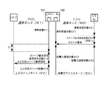
図5は、OLT11−ONU #n間がPONスリープ制御によって「上り方向スリープモード」(M2)の状態であり、かつ、LAN低電力制御によってユーザ側通信装置#nからONU #nへの通信が「低電力アイドルモード」(M4)の状態である場合に、ユーザ側通信装置(UT)#nが送信したフレームをOLT11の上位側装置に転送を開始するときの、フレームの流れと、各装置の状態の変化を表すシーケンス図である。
FIG. 5 shows that the state between the
OLT11−ONU #n間がPONスリープ制御によって「上り方向スリープモード」(M2)の状態であるとき、ONU #nのPONインタフェース部131は、「送信スリープ状態」(S13)にある。また、LAN低電力制御によってユーザ側通信装置#nからONU #nへの通信が「低電力アイドルモード」(M4)の状態であるとき、UT #nの送信側LANインタフェースは「低電力送受信状態」(S33)であり、ONU #nの受信側LANインタフェース部132は「低電力受信状態」(S22)にある。
なお、UT #nの送信側LANインタフェースとONU #nの受信側LANインタフェース部132との間の信号は、送受信を停止する時間Tqと、リフレッシュ信号を送受信する時間Trとが交互に繰り返され、低電力アイドルモードで間欠的に通信が行われる。
When the
The signal between the transmission-side LAN interface of UT #n and the reception-side
ここで、UT #nの送信側LANインタフェースが、「低電力送受信状態」(S33)から、アイドル信号をONU #nに送信する時間Twの「アイドル信号送信状態」(S34)を経て、フレームをONU #nに送信可能な状態である「通常送信状態」(S35)に移行し、フレームをONU #nに送信する。 Here, the transmission side LAN interface of the UT #n transmits the frame from the “low power transmission / reception state” (S33) through the “idle signal transmission state” (S34) of the time Tw for transmitting the idle signal to the ONU #n. The process proceeds to the “normal transmission state” (S35), which is a state in which transmission to ONU #n is possible, and the frame is transmitted to ONU #n.
この「低電力送受信状態」から「アイドル信号送信状態」を経て「通常送信状態」に至る状態の遷移は、例えば、UT #nのユーザが電話をかけるために行ったUT #nの操作を契機として、UT #nが行う。この場合、UT #nのLANインタフェースは、セッションの開始を要求するSIP INVITEに相当するフレームをONU #nに送信する。 The transition from the “low power transmission / reception state” to the “normal transmission state” through the “idle signal transmission state” is triggered by, for example, the operation of UT #n performed by the user of UT #n to make a call. As UT #n. In this case, the LAN interface of UT #n transmits a frame corresponding to SIP INVITE requesting the start of the session to ONU #n.
また、上述した状態の遷移は、UT #nに外部(たとえばSIPサーバ)から電話がかかってきたことを示すSIP INVITEに相当するフレームを、ONU #nを介してUT #nが受信したことを契機として、UT #nが行う。
この場合、UT #nのLANインタフェースは、呼び出し中を表す応答信号であるSIP 180 Ringingに相当するフレームをONU #nに送信する。このように、ユーザ側通信装置#nのLANインタフェースは、通信を行わない期間中は、LAN低電力制御によって低電力送受信状態と送信リフレッシュ状態を繰り返し、フレーム送信が必要となった時点で、低電力送受信状態からアイドル信号をONU #nに送信する一定時間のアイドル送信状態を経て、フレームをONU #nに送信可能な状態である通常送信状態に移行し、前記フレームをONU #nに送信する。
In addition, the state transition described above indicates that UT #n has received a frame corresponding to SIP INVITE indicating that a call has been received from outside (for example, a SIP server) to UT #n via ONU #n. As an opportunity, UT #n performs.
In this case, the LAN interface of UT #n transmits to ONU #n a frame corresponding to SIP 180 Ringing, which is a response signal indicating that the call is in progress. As described above, the LAN interface of the user side communication device #n repeats the low power transmission / reception state and the transmission refresh state by the LAN low power control during the period in which communication is not performed, and is low when frame transmission is required. From the power transmission / reception state, the idle signal is transmitted to the ONU #n for a certain period of time, then the normal transmission state in which the frame can be transmitted to the ONU #n is entered, and the frame is transmitted to the ONU #n. .
一方、ONU #nのLANインタフェースは、「低電力受信状態」(S22)においてUT #nからのアイドル信号の受信を契機として、UT #nから送信されたフレームを受信可能な「通常受信状態」(S23)へと移行し、UT #nから送信されたフレームを受信する。 On the other hand, the LAN interface of ONU #n is a “normal reception state” in which a frame transmitted from UT #n can be received in response to reception of an idle signal from UT #n in “low power reception state” (S22). The process proceeds to (S23), and the frame transmitted from UT #n is received.
このとき、ONU #nのLANインタフェース部132は、UT #nからのアイドル信号を受信したこと、または、低電力受信状態から通常受信状態に移行したことをLANウェイクアップ通知信号bによってPONインタフェース部131に通知する。
At this time, the
ONU #nのPONインタフェース部131は、LANウェイクアップ通知信号bを受信することによって、「上り方向スリープ状態」(S13)から、OLTに通常モードに戻ることを要求するための信号(ウェイクアップ要求信号)を送信可能となるまで(OLTからのGATE信号を受信し前記GATE信号が示す送信時刻となるまで)待つ「ウェイクアップ要求信号送信待ち状態」(S14)に移行し、さらに、ウェイクアップ要求信号の送信によって、「通常状態」(S15)へと移行する。さらに、ONU #nのLANインタフェース部132が受信したUT #nから送信されたフレームを、通常状態へと移行したONU #nのPONインタフェース部131が、OLT11からのGATE信号を受信し前記GATE信号に基づいて送信する。
Upon receiving the LAN wakeup notification signal b, the
[スリープモードから通常モードへの他の移行シーケンス]
上述した本実施の形態の説明では、ONU #nのLANインタフェース部132が「低電力受信状態」(S22)から「通常受信状態」(S23)に移行したことを契機として、ONU #nのPONインタフェース部131が「上り方向スリープ状態(送信スリープ状態)」(S13)から「ウェイクアップ要求信号送信待ち状態」(S14)に移行するものとしたが、ONU #nのPONインタフェース部131が「上り方向スリープ状態(送信スリープ状態)」(S13)から「ウェイクアップ要求信号送信待ち状態」(S14)に移行するシーケンスについても、様々な変形が可能である。
[Other transition sequences from sleep mode to normal mode]
In the description of the present embodiment described above, the ONU #n PON is triggered when the
一例として、ONU #nのLANインタフェース部132が「低電力受信状態」(S22)から「通常受信状態」(S23)に移行してから時間Twf以内に、ユーザ側通信装置#nから送信されたフレームをLwfバイト以上受信した場合に、ONU #nのPONインタフェース部132が送信スリープ状態からウェイクアップ要求信号送信待ち状態に移行するシーケンスが可能である。
As an example, the
これは、仮にONU #nのPONインタフェース部131が「上り方向スリープ状態(送信スリープ状態)」(S13)であっても、所定のLwfバイト未満のフレームであれば、時間Twf以内にONU #nからOLTに前記フレームを送信することができるような場合に、Lwfバイト未満のフレーム(例えばユーザ側通信装置 #nがSIPサーバに登録を維持するために送信するフレーム)をユーザ側通信装置#nから送信したときにONU #nのPONインタフェース部131が送信スリープ状態を維持しつつ前記フレームをOLT11に転送できるため、PONインタフェース部131に関わる消費電力を低減することができるという効果がある。
Even if the
また上記のシーケンスにおいて、ONU #nのLANインタフェース部132が「低電力受信状態」(S22)から「通常受信状態」(S23)に移行してから、ONU #nのPONインタフェース部131が「上り方向スリープ状態(送信スリープ状態)」(S13)から「通常状態」(S15)へと移行するまでの遅延があるが、この遅延によって、ONU #nの通常受信状態となったLANインタフェース部132で受信したUT #nから受信したフレームを、通常状態に移行が完了していないONU #nのPONインタフェース部131から送信することができない期間が発生する。この期間に受信したフレームはONU #n内に保留されるが、ONU #nのバッファ容量に限りがあるため、受信した全てのフレームをONU #n内に保留することができず、廃棄されるフレームが発生する場合がある。
In the above sequence, the ONU #n
そこで、前記フレームの廃棄が生じないように、ユーザ側通信装置#nからONU #nへのフレーム送信を停止させるための、IEEE 802.3xとして標準化されたフロー制御を行う。具体的には、ONU #n内に保留されたフレームの数あるいはデータ量が所定量以上となったことを契機として、ONU #nはポーズフレームをユーザ側通信装置#nに送信する。また、ONU #nが複数のキューを持ち、ユーザ側通信装置#nからONU #nへのフレームのヘッダに記載された優先度に応じて、前記フレームが蓄積されるキューが選択される場合には、フレームの優先度によってONU #n内のフレームの保留状況が異なるので、ユーザ側通信装置#nからONU #nへのフレーム送信を優先度に応じて停止させるための、IEEE 802.1Qbbとして標準化されたフロー制御を行うことも可能である。 Therefore, in order to prevent the frame from being discarded, flow control standardized as IEEE 802.3x for stopping frame transmission from the user-side communication device #n to the ONU #n is performed. Specifically, the ONU #n transmits a pause frame to the user-side communication device #n when the number of frames or the amount of data held in the ONU #n becomes a predetermined amount or more. In addition, when ONU #n has a plurality of queues and the queue in which the frames are stored is selected according to the priority described in the header of the frame from user side communication device #n to ONU #n. Since the frame hold status in the ONU #n differs depending on the frame priority, IEEE 802.1Qbb is used to stop frame transmission from the user side communication device #n to the ONU #n according to the priority. It is also possible to perform standardized flow control.
フロー制御の解除(フロー制御の解除を示すポーズフレームをユーザ側通信装置#nからONU #nへ送信すること)は、ONU #nのPONインタフェース部131が「上り方向スリープ状態(送信スリープ状態)」(S13)から「通常状態」(S15)へと移行した時点、あるいは「通常状態」(S15)への移行によってONU #n内に保留されたフレームがOLTに送信されて、その量が減少して廃棄が生じなくなったと判断できる量以下になった時点で行う。
The release of flow control (transmitting a pause frame indicating release of flow control from the user side communication device #n to the ONU #n) is performed by the
また上記のシーケンスにおいて、ONU #nのLANインタフェース部132が「低電力受信状態」(S22)から「通常受信状態」(S23)に移行したことを契機としてフロー制御によってUT #nからONU #nへのフレーム送信を停止させ(すなわち、ポーズフレームをユーザ側通信装置#nに送信し)、ONU #nのPONインタフェース部131が「上り方向スリープ状態(送信スリープ状態)」(S13)から「通常状態」(S15)へと移行した時点で前記フロー制御を解除することも可能である。
In the above sequence, when the
また前記フロー制御の解除を、ONU #nのPONインタフェース部131が「上り方向スリープ状態(送信スリープ状態)」(S13)から「通常状態」(S15)へと移行する時点よりも前に行うことで、PONインタフェース部131が「通常状態」(S15)になった時点で、ONU #nにUT #nがフロー制御の解除後に送信した上りフレームが蓄積されていることになり、PONインタフェース部131が通常状態になった直後から、ONU #nは上りフレームをOLTに送信できる。
Further, the flow control is canceled before the time when the
なお、本実施の形態においては、UT #nがIP電話端末である場合を例に説明しているが、これ以外の端末装置であっても、UT #nからONU #nへの通信を開始するときの最初のフレームを送信する場合に、本実施の形態において説明したユーザ側通信装置#nとONU #nの状態遷移のシーケンスを採用できる。 In this embodiment, the case where UT #n is an IP telephone terminal has been described as an example, but communication from UT #n to ONU #n is started even with other terminal devices. When the first frame is transmitted, the state transition sequence of the user side communication device #n and ONU #n described in the present embodiment can be adopted.
例えば、UT #nの一例はホームゲートウェイであり、このホームゲートウェイには、1個以上の宅内通信端末が接続され、この宅内通信端末が送出した信号をフレームとしてONU #nに転送し、ONU #nから受信したフレームをこの宅内通信端末への信号として送出する。この場合、ユーザ側通信装置#n(ホームゲートウェイ)のLANインタフェース(ONU #nとLANを介して接続するインタフェース)が、低電力送受信状態から通常送信状態に移行する契機の例は、このホームゲートウェイに接続された宅内通信端末が送出した信号をホームゲートウェイが受信し、信号を上りフレームとしてONU #nに送信する必要が生じたことである。 For example, one example of the UT #n is a home gateway. One or more home communication terminals are connected to the home gateway, and a signal transmitted from the home communication terminal is transferred as a frame to the ONU #n. The frame received from n is transmitted as a signal to this home communication terminal. In this case, an example of the opportunity when the LAN interface (interface connected to the ONU #n via the LAN) of the user side communication device #n (home gateway) shifts from the low power transmission / reception state to the normal transmission state is shown in this home gateway. The home gateway receives the signal transmitted from the home communication terminal connected to the network, and the signal needs to be transmitted to the ONU #n as an upstream frame.
また、別の例は、前記ホームゲートウェイに搭載されたCPUで動作しているアプリケーションソフトウェアがフレームの送受信を必要とする活動状態となったことである。 Another example is that application software running on the CPU mounted on the home gateway has entered an active state that requires frame transmission / reception.
なお、本実施の形態では、OLT11−ONU #n間がPONスリープ制御によって上り方向スリープモードとなる場合について示したが、双方向スリープモードの場合も同様のシーケンスを採用することが可能である。なお、PONスリープ制御によって双方向スリープモードとなった場合は、ONU #nからユーザ側通信装置#nへの下り方向のLAN低電力制御によって、双方向スリープモードの期間中に、ONU #nからユーザ側通信装置#nへの通信を低電力モードの状態とすることが可能である。
In the present embodiment, the case where the
以上のように、本実施の形態に係るONUによれば、LAN低電力制御のためにユーザ側通信装置からONUに通知されるスリープ信号やアイドル信号をLANインタフェース部132で受信したことを契機として、LANスリープ通知信号aおよびLANウェイクアップ通知信号bをLANインタフェース部132からPONインタフェース部131に渡すことによって、PONスリープ制御によりスリープモードへの移行が可能となったことやPONスリープ制御により通常モードへの移行が必要となったことを、低遅延で、PONスリープ制御に反映させることができる。
As described above, according to the ONU according to the present embodiment, the
本発明は、FTTH(Fiber To The Home)など、PONシステムを用いた通信システムに利用することができる。 The present invention can be used for a communication system using a PON system such as FTTH (Fiber To The Home).
1…PONシステム、11…OLT、12…光分岐結合器、13−1〜13−n…ONU、14−1〜14−n…ユーザ側通信装置、15,16−1〜16−n…光ファイバ、17−1〜17−n…LAN、131…PONインタフェース部、132…LANインタフェース部。
DESCRIPTION OF
Claims (6)
受動光網を介して局側光回線終端装置と接続されて、光信号と電気信号とを相互に変換して前記局側光終端装置とフレームを送受信するとともに、フレームを送信または送受信する機能を制限して消費電力を低減可能なスリープ状態となることができる第2のインタフェースとを備え、
前記第2のインタフェースは、前記第1のインタフェースが前記スリープ信号を受信したことまたは前記低電力送受信状態となったことを契機として前記スリープ状態となり、
前記第1のインタフェースは、
前記ユーザ側通信装置からフレームを受信するとともに、前記第2のインタフェースが前記局側光終端装置から受信したフレームの少なくとも一部を前記ユーザ側通信装置に送信する第1の送受信部と、
前記ユーザ側通信装置がフレームを送信または受信する機能を制限してフレームの送受信に関わる消費電力を低減する低電力送受信状態にあることを示すスリープ信号を前記第1のインタフェースが受信すると、前記第1の送受信部のフレームを送信または受信する機能を制限して、前記第1のインタフェースを、前記第1のインタフェースの消費電力を低減可能な低電力送受信状態とする第1の状態制御部とを含み、
前記第2のインタフェースは、
光信号と電気信号とを相互に変換して、前記局側光終端装置からフレームを受信するとともに、前記第1のインタフェースが前記ユーザ側通信装置から受信したフレームの少なくとも一部を前記局側光回線終端装置に送信する第2の送受信部と、
前記第1のインタフェースが前記スリープ信号を受信したことまたは前記低電力送受信状態となったことを契機として、前記第2の送受信部のフレームを送信または送受信する機能を制限して、前記第2のインタフェースを、前記第2のインタフェースの消費電力を低減可能なスリープ状態とする第2の状態制御部とを含む
ことを特徴とするユーザ側光回線終端装置。 Power consumption related to transmission / reception of frames by being connected to a user-side communication device via a user network, transmitting / receiving frames to / from the user-side communication device, and restricting functions of the user-side communication device to transmit / receive frames A first interface that is in a low power transmission / reception state capable of reducing power consumption by limiting a function of transmitting or receiving a frame when receiving a sleep signal indicating that the low power transmission / reception state is reduced;
Connected to the station side optical line terminator through the passive optical network, and converts the optical signal and the electrical signal to each other to transmit / receive a frame to / from the station side optical terminator and to transmit / receive the frame A second interface capable of entering a sleep state capable of limiting and reducing power consumption,
Said second interface, Ri Do and the sleep state that the first interface becomes a sleep signal or that the low power transceiver state has been received as a trigger,
The first interface is:
A first transmission / reception unit that receives a frame from the user-side communication device and transmits at least a part of the frame received by the second interface from the station-side optical terminal device to the user-side communication device;
When the first interface receives a sleep signal indicating that the user side communication device is in a low power transmission / reception state that limits a function of transmitting or receiving a frame to reduce power consumption related to frame transmission / reception, the first interface receives the sleep signal. A first state control unit that limits a function of transmitting or receiving a frame of one transmission / reception unit and sets the first interface to a low-power transmission / reception state capable of reducing power consumption of the first interface; Including
The second interface is:
An optical signal and an electrical signal are mutually converted to receive a frame from the station side optical termination device, and at least a part of the frame received by the first interface from the user side communication device is converted to the station side light. A second transceiver for transmitting to the line termination device;
When the first interface receives the sleep signal or enters the low power transmission / reception state, the function of transmitting or transmitting / receiving a frame of the second transmission / reception unit is limited, and the second interface A user-side optical line termination device comprising: a second state control unit that sets an interface to a sleep state in which power consumption of the second interface can be reduced .
さらに前記局側光終端装置に送信するフレームを保留するバッファを備え、
前記第2の状態制御部は、
前記第1のインタフェースが前記低電力送受信状態となり、かつ、前記バッファに保留されたフレームの量が所定の値以下となった後に、前記第2のインタフェースを前記スリープ状態とする
ことを特徴とするユーザ側光回線終端装置。 In the user side optical network unit according to claim 1,
Furthermore, a buffer for holding a frame to be transmitted to the station side optical termination device is provided,
The second state controller is
The second interface is set in the sleep state after the first interface is set in the low power transmission / reception state and the amount of frames held in the buffer becomes equal to or less than a predetermined value. An optical line termination device on the user side.
前記第1の状態制御部は、さらに、
前記低電力送受信状態にある前記第1のインタフェースが、前記ユーザ側通信装置が前記低電力送受信状態からフレームを送信または受信する機能を制限しない通常送受信状態となることを示すアイドル信号を受信すると、前記第1のインタフェースを、前記低電力送受信状態から前記第1の送受信部が前記ユーザ側通信装置とフレームを送信または受信する機能を制限しない通常送受信状態とし、
前記第2の状態制御部は、
前記第1のインタフェースが前記アイドル信号を受信したことまたは前記低電力送受信状態から前記通常送受信状態となったことを契機として、前記第2のインタフェースを前記スリープ状態から前記第2の送受信部がフレームを送信または送受信する機能を制限しない通常送受信状態とする
ことを特徴とするユーザ側光回線終端装置。 In the user side optical network unit according to claim 1 or 2,
The first state control unit further includes:
When the first interface in the low power transmission / reception state receives an idle signal indicating that the user side communication device is in a normal transmission / reception state that does not restrict a function of transmitting or receiving a frame from the low power transmission / reception state, The first interface is set to a normal transmission / reception state in which the first transmission / reception unit does not restrict a function of transmitting or receiving a frame with the user-side communication device from the low power transmission / reception state,
The second state controller is
When the first interface receives the idle signal or when the low power transmission / reception state is changed to the normal transmission / reception state, the second transmission / reception unit transmits a frame from the sleep state to the second transmission / reception unit. A user-side optical line termination device characterized by having a normal transmission / reception state in which a function of transmitting or transmitting / receiving is not restricted .
受動光網を介して局側光回線終端装置と接続されて、光信号と電気信号とを相互に変換して前記局側光終端装置とフレームを送受信するとともに、フレームを送信または送受信する機能を制限して消費電力を低減可能なスリープ状態となることができる第2のインタフェースと
を備え、
前記第1のインタフェースは、
前記ユーザ側通信装置からフレームを受信するとともに、前記第2のインタフェースが前記局側光終端装置から受信したフレームの少なくとも一部を前記ユーザ側通信装置に送信する第1の送受信部と、
フレームを送信または受信する機能を制限して消費電力を低減可能な低電力送受信状態にある前記第1のインタフェースが、前記ユーザ側通信装置がフレームを送信または受信する機能を制限してフレームの送受信に関わる消費電力を低減する低電力送受信状態からフレームを送信または受信する機能を制限しない通常送受信状態となることを示すアイドル信号を受信すると、前記第1のインタフェースを、前記低電力送受信状態から前記第1の送受信部が前記ユーザ側通信装置とフレームを送信または受信する機能を制限しない通常送受信状態とする第1の状態制御部と
を備え、
前記第2のインタフェースは、
光信号と電気信号とを相互に変換して、前記局側光終端装置からフレームを受信するとともに、前記第1のインタフェースが前記ユーザ側通信装置から受信したフレームの少なくとも一部を前記局側光回線終端装置に送信する第2の送受信部と、
前記第1のインタフェースが前記アイドル信号を受信したことまたは前記低電力送受信状態から前記通常送受信状態となったことを契機として、前記第2のインタフェースを前記スリープ状態から前記第2の送受信部がフレームを送信または送受信する機能を制限しない通常送受信状態とする第2の状態制御部と
を備えたことを特徴とするユーザ側光回線終端装置。 Power consumption related to transmission / reception of frames by being connected to a user-side communication device via a user network, transmitting / receiving frames to / from the user-side communication device, and restricting functions of the user-side communication device to transmit / receive frames A first interface that is in a low power transmission / reception state capable of reducing power consumption by limiting a function of transmitting or receiving a frame when receiving a sleep signal indicating that the low power transmission / reception state is reduced;
Connected to the station side optical line terminator through the passive optical network, and converts the optical signal and the electrical signal to each other to transmit / receive a frame to / from the station side optical terminator and to transmit / receive the frame A second interface capable of entering a sleep state capable of limiting and reducing power consumption;
With
The first interface is:
A first transmission / reception unit that receives a frame from the user-side communication device and transmits at least a part of the frame received by the second interface from the station-side optical terminal device to the user-side communication device;
The first interface that is in a low power transmission / reception state capable of reducing power consumption by restricting the function of transmitting or receiving frames restricts the function of the user side communication device to transmit or receive frames and transmits / receives frames. When receiving an idle signal indicating that a normal transmission / reception state in which a function of transmitting or receiving a frame is not restricted is received from a low-power transmission / reception state that reduces power consumption related to the first interface, the first interface is changed from the low-power transmission / reception state to the A first state control unit that sets a normal transmission / reception state in which the first transmission / reception unit does not restrict a function of transmitting or receiving a frame with the user-side communication device;
With
The second interface is:
An optical signal and an electrical signal are mutually converted to receive a frame from the station side optical termination device, and at least a part of the frame received by the first interface from the user side communication device is converted to the station side light. A second transceiver for transmitting to the line termination device;
When the first interface receives the idle signal or when the low power transmission / reception state is changed to the normal transmission / reception state, the second transmission / reception unit transmits a frame from the sleep state to the second transmission / reception unit. A second state control unit that sets a normal transmission / reception state without limiting a function of transmitting or transmitting
User optical network unit, characterized in that it comprises a.
前記ユーザ側通信装置がフレームを送信または受信する機能を制限してフレームの送信または受信に関わる消費電力を低減する低電力送受信状態にあることを示すスリープ信号を前記第1のインタフェースが受信するステップと、
前記スリープ信号を受信した前記第1のインタフェースが、前記ユーザ側通信装置とフレームを送信または受信する機能を制限しない通常送受信状態から、フレームを送信または受信する機能を制限して、前記第1のインタフェースの消費電力を低減可能な低電力送受信状態とするステップと、
前記第1のインタフェースが前記スリープ信号を受信したことまたは前記低電力送受信状態となったことを契機として、前記第2の送受信部のフレームを送信または送受信する機能を制限して、前記第2のインタフェースを、前記第2のインタフェースの消費電力を低減可能なスリープ状態とするステップとを有し、
前記第2のインタフェースを前記スリープ状態とするステップは、
前記第1のインタフェースが前記低電力送受信状態となり、かつ、前記バッファに保留されたフレームの量が所定の値以下となった後に、前記第2のインタフェースを前記スリープ状態とする
ことを特徴とするユーザ側光回線終端装置の消費電力制御方法。 A first interface connected to the user-side communication device via the user network, a second interface connected to the station-side optical line termination device via the passive optical network, and the station-side optical termination device A buffer for holding the frame, wherein the first interface transmits at least part of the frame received from the user side communication device to the station side optical line termination device from the second interface, and the second interface In the power consumption control method for a user-side optical line terminator, wherein an interface transmits at least a part of a frame received from the station-side optical terminator from the first interface to the user-side communication device.
The first interface receives a sleep signal indicating that the user side communication device is in a low power transmission / reception state that limits a function of transmitting or receiving a frame to reduce power consumption related to frame transmission or reception. When,
The first interface that has received the sleep signal restricts the function of transmitting or receiving a frame from the normal transmission / reception state in which the function of transmitting or receiving a frame with the user-side communication device is not restricted, and the first interface A step of setting a low power transmission / reception state capable of reducing power consumption of the interface;
When the first interface receives the sleep signal or enters the low power transmission / reception state, the function of transmitting or transmitting / receiving a frame of the second transmission / reception unit is limited, and the second interface Setting the interface to a sleep state capable of reducing power consumption of the second interface,
The step of setting the second interface to the sleep state includes:
After the first interface enters the low power transmission / reception state and the amount of frames held in the buffer falls below a predetermined value, the second interface enters the sleep state.
A power consumption control method for a user side optical network unit.
前記低電力送受信状態にある前記第1のインタフェースが、前記ユーザ側通信装置が前記低電力送受信状態からフレームを送信または受信する機能を制限しない通常送受信状態となることを示すアイドル信号を受信するステップと、
前記アイドル信号を受信した前記第1のインタフェースを、前記低電力送受信状態から前記ユーザ側通信装置とフレームを送信または受信する機能を制限しない通常送受信状態とするステップと、
前記第1のインタフェースが前記アイドル信号を受信したことまたは前記低電力送受信状態から前記通常送受信状態となったことを契機として、前記第2のインタフェースを前記スリープ状態からフレームを送信または送受信する機能を制限しない通常送受信状態とするステップと
を有することを特徴とするユーザ側光回線終端装置の消費電力制御方法。 In the power consumption control method of the user side optical line termination device according to claim 5,
Receiving an idle signal indicating that the first interface in the low power transmission / reception state is in a normal transmission / reception state in which the user-side communication device does not restrict a function of transmitting or receiving a frame from the low power transmission / reception state; When,
Setting the first interface that has received the idle signal to a normal transmission / reception state that does not limit a function of transmitting or receiving a frame with the user-side communication device from the low-power transmission / reception state;
A function of transmitting or transmitting / receiving a frame from the sleep state to the second interface when the first interface has received the idle signal or has changed from the low power transmission / reception state to the normal transmission / reception state. Steps for normal transmission / reception without restriction
A power consumption control method for a user-side optical line terminator.
Priority Applications (1)
| Application Number | Priority Date | Filing Date | Title |
|---|---|---|---|
| JP2012282340A JP5882886B2 (en) | 2012-12-26 | 2012-12-26 | User side optical line terminator and power consumption control method for user side optical line terminator |
Applications Claiming Priority (1)
| Application Number | Priority Date | Filing Date | Title |
|---|---|---|---|
| JP2012282340A JP5882886B2 (en) | 2012-12-26 | 2012-12-26 | User side optical line terminator and power consumption control method for user side optical line terminator |
Publications (2)
| Publication Number | Publication Date |
|---|---|
| JP2014127803A JP2014127803A (en) | 2014-07-07 |
| JP5882886B2 true JP5882886B2 (en) | 2016-03-09 |
Family
ID=51407008
Family Applications (1)
| Application Number | Title | Priority Date | Filing Date |
|---|---|---|---|
| JP2012282340A Expired - Fee Related JP5882886B2 (en) | 2012-12-26 | 2012-12-26 | User side optical line terminator and power consumption control method for user side optical line terminator |
Country Status (1)
| Country | Link |
|---|---|
| JP (1) | JP5882886B2 (en) |
Families Citing this family (2)
| Publication number | Priority date | Publication date | Assignee | Title |
|---|---|---|---|---|
| JP6441745B2 (en) * | 2015-06-01 | 2018-12-19 | 日本電信電話株式会社 | Cooperation communication system and state cooperation method |
| JP2018207457A (en) | 2017-06-09 | 2018-12-27 | 富士通株式会社 | Optical terminal station apparatus, optical terminating apparatus, and communication control method |
Family Cites Families (6)
| Publication number | Priority date | Publication date | Assignee | Title |
|---|---|---|---|---|
| JP2007089027A (en) * | 2005-09-26 | 2007-04-05 | Mitsubishi Electric Corp | Optical network unit |
| JP2008113193A (en) * | 2006-10-30 | 2008-05-15 | Mitsubishi Electric Corp | Subscriber side apparatus and its power consumption control system |
| JP5302857B2 (en) * | 2009-11-10 | 2013-10-02 | 富士通テレコムネットワークス株式会社 | Power saving control system, power saving control method, and subscriber side device |
| JP5463165B2 (en) * | 2010-02-26 | 2014-04-09 | 株式会社日立製作所 | Recovery method from ONU sleep state in PON system that can save power |
| JP5538271B2 (en) * | 2011-02-24 | 2014-07-02 | 三菱電機株式会社 | Optical communication system and communication control method |
| JP2013026818A (en) * | 2011-07-21 | 2013-02-04 | Mitsubishi Electric Corp | Communication system, communication method, and slave station side device |
-
2012
- 2012-12-26 JP JP2012282340A patent/JP5882886B2/en not_active Expired - Fee Related
Also Published As
| Publication number | Publication date |
|---|---|
| JP2014127803A (en) | 2014-07-07 |
Similar Documents
| Publication | Publication Date | Title |
|---|---|---|
| JP4960532B2 (en) | Station side communication device, subscriber side communication device, communication system, and communication method | |
| JP5106683B2 (en) | COMMUNICATION METHOD, OPTICAL COMMUNICATION SYSTEM, USER-SIDE OPTICAL LINE TERMINAL DEVICE, STATION-SIDE OPTICAL LINE TERMINAL DEVICE, AND CONTROL DEVICE | |
| CN102170598B (en) | Method of recovery from sleep state of an ONU in a PON system capable of power saving | |
| WO2014103804A1 (en) | Optical-wireless access system | |
| US20150326318A1 (en) | Relay device, station side device, and communication system and communication method using relay device | |
| JP2007049376A (en) | Optical subscriber line terminal station, optical subscriber line terminating device, and down band control method | |
| JP2012142698A (en) | Station side device, communication system and communication control method | |
| JP5538271B2 (en) | Optical communication system and communication control method | |
| WO2011155242A1 (en) | Data relay device and function control method for same | |
| JP5882886B2 (en) | User side optical line terminator and power consumption control method for user side optical line terminator | |
| JP2011229094A (en) | Optical transmission line terminator | |
| JP5578023B2 (en) | Station side device, home side device, optical communication system, and control method of optical communication system | |
| JP2013026818A (en) | Communication system, communication method, and slave station side device | |
| JP5718258B2 (en) | Subscriber side communication device, subscriber side gateway device, and home communication system | |
| JP5325168B2 (en) | Passive optical network system | |
| JP5592320B2 (en) | Communication apparatus and power saving method for communication apparatus | |
| JP6028395B2 (en) | Power saving control system, master station device, and power saving control program | |
| JP6296534B2 (en) | Power saving control method for communication apparatus and communication apparatus | |
| JP5383844B2 (en) | Station side communication apparatus, subscriber side communication apparatus, communication system, communication method, and control apparatus | |
| JP6713816B2 (en) | Subscriber side communication device and sleep control method | |
| JP2012257341A (en) | Communication method, optical communication system, user-side optical line termination device, office-side optical line termination device and control device | |
| JP2016140011A (en) | Optical network unit | |
| JP5757190B2 (en) | Optical communication system, control method of optical communication system, and home side apparatus | |
| JP6189712B2 (en) | Power saving control method for communication apparatus and communication apparatus | |
| JP5504223B2 (en) | Optical communication system, optical subscriber line termination device, and optical communication method |
Legal Events
| Date | Code | Title | Description |
|---|---|---|---|
| A621 | Written request for application examination |
Free format text: JAPANESE INTERMEDIATE CODE: A621 Effective date: 20150128 |
|
| A977 | Report on retrieval |
Free format text: JAPANESE INTERMEDIATE CODE: A971007 Effective date: 20151021 |
|
| A131 | Notification of reasons for refusal |
Free format text: JAPANESE INTERMEDIATE CODE: A131 Effective date: 20151110 |
|
| A521 | Request for written amendment filed |
Free format text: JAPANESE INTERMEDIATE CODE: A523 Effective date: 20160105 |
|
| TRDD | Decision of grant or rejection written | ||
| A01 | Written decision to grant a patent or to grant a registration (utility model) |
Free format text: JAPANESE INTERMEDIATE CODE: A01 Effective date: 20160202 |
|
| A61 | First payment of annual fees (during grant procedure) |
Free format text: JAPANESE INTERMEDIATE CODE: A61 Effective date: 20160204 |
|
| R150 | Certificate of patent or registration of utility model |
Ref document number: 5882886 Country of ref document: JP Free format text: JAPANESE INTERMEDIATE CODE: R150 |
|
| LAPS | Cancellation because of no payment of annual fees |