JP5882877B2 - Game machine - Google Patents
Game machine Download PDFInfo
- Publication number
- JP5882877B2 JP5882877B2 JP2012244814A JP2012244814A JP5882877B2 JP 5882877 B2 JP5882877 B2 JP 5882877B2 JP 2012244814 A JP2012244814 A JP 2012244814A JP 2012244814 A JP2012244814 A JP 2012244814A JP 5882877 B2 JP5882877 B2 JP 5882877B2
- Authority
- JP
- Japan
- Prior art keywords
- output
- error
- signal
- winning
- game
- Prior art date
- Legal status (The legal status is an assumption and is not a legal conclusion. Google has not performed a legal analysis and makes no representation as to the accuracy of the status listed.)
- Expired - Fee Related
Links
Images


Description
所定の遊技を行うことが可能なパチンコ遊技機等の遊技機に関する。 The present invention relates to a gaming machine such as a pachinko gaming machine capable of performing a predetermined game.
遊技機として、遊技媒体である遊技球を発射装置によって遊技領域に発射し、遊技領域に設けられている入賞口などの入賞領域に遊技球が入賞すると、所定個の賞球が遊技者に払い出されるものがある。さらに、識別情報を可変表示(「変動」ともいう。)可能な可変表示装置が設けられ、可変表示装置において識別情報の可変表示の表示結果が特定表示結果となった場合に、遊技状態(遊技機の状態。よって、具体的には、遊技機が制御されている状態。)を、所定の遊技価値を遊技者に与えるように構成されたものがある。 As a gaming machine, a game ball, which is a game medium, is launched into a game area by a launching device, and when a game ball wins a prize area such as a prize opening provided in the game area, a predetermined number of prize balls are paid out to the player. There is something to be done. Further, a variable display device capable of variably displaying the identification information (also referred to as “fluctuation”) is provided, and when the display result of the variable display of the identification information becomes a specific display result in the variable display device, the game state (game There is a machine configured to give a predetermined game value to a player (specifically, a state in which a gaming machine is controlled).
なお、遊技価値とは、遊技機の遊技領域に設けられた可変入賞球装置の状態が打球が入賞しやすい遊技者にとって有利な状態になることや、遊技者にとって有利な状態になるための権利を発生させたりすることや、賞球払出の条件が成立しやすくなる状態になることである。 The game value is the right that the state of the variable winning ball apparatus provided in the gaming area of the gaming machine becomes advantageous for a player who is easy to win, and the right for becoming advantageous for a player. In other words, or a condition for winning a prize ball is easily established.
パチンコ遊技機では、始動入賞口に遊技球が入賞したことにもとづいて可変表示装置において開始される特別図柄(識別情報)の可変表示の表示結果として、あらかじめ定められた特定の表示態様が導出表示された場合に、「大当り」が発生する。なお、導出表示とは、図柄(最終停止図柄)を最終的に停止表示させることである。大当りが発生すると、例えば、大入賞口が所定回数開放して打球が入賞しやすい大当り遊技状態に移行する。そして、各開放期間において、所定個(例えば、10個)の大入賞口への入賞があると大入賞口は閉成する。そして、大入賞口の開放回数は、所定回数(例えば、15ラウンド)に固定されている。なお、各開放について開放時間(例えば、29秒)が決められ、入賞数が所定個に達しなくても開放時間が経過すると大入賞口は閉成する。以下、各々の大入賞口の開放期間をラウンドということがある。また、ラウンドにおける遊技をラウンド遊技ということがある。 In a pachinko machine, a specific display mode determined in advance is derived and displayed as a display result of variable display of special symbols (identification information) that is started in the variable display device based on the winning of a game ball at the start winning opening. If this happens, a “big hit” will occur. The derived display is to finally stop and display a symbol (final stop symbol). When the big hit occurs, for example, the big winning opening is opened a predetermined number of times, and the game shifts to a big hit gaming state where the hit ball is easy to win. And in each open period, if there is a prize for a predetermined number (for example, 10) of the big prize opening, the big prize opening is closed. And the number of times of opening the special winning opening is fixed to a predetermined number (for example, 15 rounds). An opening time (for example, 29 seconds) is determined for each opening, and even if the number of winnings does not reach a predetermined number, the big winning opening is closed when the opening time elapses. Hereinafter, the opening period of each special winning opening may be referred to as a round. A game in a round may be referred to as a round game.
また、可変表示装置において、最終停止図柄(例えば、左中右図柄のうち中図柄)となる図柄以外の図柄が、所定時間継続して、特定の表示結果と一致している状態で停止、揺動、拡大縮小もしくは変形している状態、または、複数の図柄が同一図柄で同期して変動したり、表示図柄の位置が入れ替わっていたりして、最終結果が表示される前で大当り発生の可能性が継続している状態(以下、これらの状態をリーチ状態という。)において行われる演出をリーチ演出という。また、リーチ状態やその様子をリーチ態様という。さらに、リーチ演出を含む可変表示をリーチ可変表示という。そして、可変表示装置に変動表示される図柄の表示結果が特定の表示結果でない場合には「はずれ」となり、変動表示状態は終了する。遊技者は、大当りをいかにして発生させるかを楽しみつつ遊技を行う。 In the variable display device, the symbols other than the symbol that becomes the final stop symbol (for example, the middle symbol in the left, middle, and right symbols) continue for a predetermined period of time and stop and shake in a state that matches the specific display result. It can be a big hit before the final result is displayed because it is moving, scaling, or deforming, or multiple symbols change synchronously with the same symbol, or the position of the displayed symbol is switched. An effect performed in a state where the sex is continued (hereinafter, these states are referred to as reach states) is referred to as reach effect. Further, the reach state and its state are referred to as a reach mode. Furthermore, variable display including reach production is called reach variable display. Then, when the display result of the symbol variably displayed on the variable display device is not a specific display result, it becomes “out of” and the variability display state ends. A player plays a game while enjoying how to generate a big hit.
そのような遊技機において、遊技に関するエラーを検出してエラー情報を出力するように構成されたものがある。例えば、特許文献1には、入賞口に入球した遊技球を検出する入賞球検出器を備え、予め設定された所定時間内に入賞球検出器において連続的に検出される遊技球の個数を計測し、計測された遊技球の個数が入賞装置への遊技球の入球頻度に応じた個数を超える所定数以上である場合に、警報作動を行うことが記載されている。
Some of these gaming machines are configured to detect an error relating to a game and output error information. For example,
特許文献1に記載された遊技機によれば、遊技球の入賞が不正行為によるものであるか否かを判断し、不正行為であると判断した場合に、装飾ランプ等の電飾装置を全点滅させたり、スピーカから警報音を発生させたりすることでその旨を報知することができる。しかし、引用文献1には、複数の入賞検出手段に対して不正行為が同時に行われた場合の処理については記載されていない。すなわち、特許文献1に記載された遊技機では、1の入賞検出手段においてエラーが発生したことにもとづいてエラー情報を出力しているときに他の入賞検出手段においてもエラーが発生した場合には、他の入賞検出手段においてエラーが発生したことにもとづくエラー情報の出力が行われないことが考えられる。
According to the gaming machine described in
そこで、本発明は、エラー情報を出力しているときに新たにエラーが発生した場合にも、新たにエラーが発生したことにもとづくエラー情報を出力することができる遊技機を提供することを目的とする。 Therefore, an object of the present invention is to provide a gaming machine capable of outputting error information based on the occurrence of a new error even when a new error occurs while outputting the error information. And
(手段1)本発明による遊技機は、操作手段(例えば、操作ボタン120)と、第1入賞領域(例えば、始動入賞口や大入賞口、入賞口、ゲート32)に設けられ第1入賞領域を遊技媒体が通過したことを検出するための第1検出手段(例えば、始動口スイッチ14aやカウントスイッチ23、入賞口スイッチ29a,30a、ゲートスイッチ32a)と、第2入賞領域(例えば、始動入賞口や大入賞口、入賞口、ゲート32)に設けられ第2入賞領域を遊技媒体が通過したことを検出するための第2検出手段(例えば、始動口スイッチ14aやカウントスイッチ23、入賞口スイッチ29a,30a、ゲートスイッチ32a)と、第1検出手段が遊技媒体の通過を検出した時点から第1監視期間(図15に示す監視期間)を経過するまでに該第1検出手段が遊技媒体の通過を再度検出した回数を計数する第1計数手段(例えば、CPU56によって始動口スイッチ判定処理(ステップS259a)のステップS2507,S2508の処理が実行される部分)と、第2検出手段が遊技媒体の通過を検出した時点から第2監視期間(図15に示す監視期間)を経過するまでに該第2検出手段が遊技媒体の通過を再度検出した回数を計数する第2計数手段(例えば、CPU56によって入賞口スイッチ判定処理(ステップS259b)において始動口スイッチ判定処理(ステップS259a)のステップS2507,S2508に相当する処理が実行され部分)と、第1計数手段が計数した回数が所定回数となった場合に、エラーが発生したと判定する第1エラー判定手段(例えば、CPU56によって始動口スイッチ判定処理(ステップS259a)のステップS2511,S2512の処理が実行される部分)と、第2計数手段が計数した回数が所定回数となった場合に、エラーが発生したと判定する第2エラー判定手段(例えば、CPU56によって入賞口スイッチ判定処理(ステップS259b)において始動口スイッチ判定処理(ステップS259a)のステップS2511,S2512に相当する処理が実行される部分)と、第1エラー判定手段と第2エラー判定手段との少なくともいずれかによってエラーが発生したと判定された場合に、エラー情報(セキュリティ信号)を出力するエラー情報出力手段(例えば、CPU56によって情報出力処理のステップS1004〜S1015の処理が実行される部分)とを備え、エラー情報出力手段は、第1エラー判定手段と第2エラー判定手段とのいずれによってエラーが発生したと判定されたかに関わらず、共通の出力手段(例えば、ターミナル基板160に設けられたコネクタCN8)を用いて、共通の所定の出力期間(例えば、0.2秒)にわたってエラー情報を出力し、第1エラー判定手段の判定にもとづいてエラー情報を出力している出力期間内に第2エラー判定手段によってエラーが発生したと判定された場合には、該出力期間が経過し、さらに所定の待機期間が経過した後に共通の出力手段を用いて所定の出力期間にわたってエラー情報を出力し(例えば、CPU56によって情報出力処理のステップS1004〜S1015の処理が実行される部分)、第1計数手段は、計数した回数が所定回数となったことにもとづいて第1エラー判定手段によってエラーが発生したと判定された場合には、計数した回数を初期化し(例えば、CPU56によってステップS2513の処理が実行される部分)、第2計数手段は、第1計数手段による初期化の際に、計数した回数を初期化せず、第1検出手段が遊技媒体の通過を検出している状態が所定期間継続する度に、連続検出エラーが発生したと判定する第1連続検出エラー判定手段と、第2検出手段が遊技媒体の通過を検出している状態が所定期間継続する度に、連続検出エラーが発生したと判定する第2連続検出エラー判定手段と、第1連続検出エラー判定手段または第2連続検出エラー判定手段によって連続検出エラーが発生したと判定される度に、共通の出力手段を用いて特定期間にわたって連続検出エラー情報を出力する連続検出エラー情報出力手段とをさらに備えたことを特徴とする。
そのような構成により、エラー情報を出力しているときに新たにエラーが発生した場合にも、新たにエラーが発生したことにもとづくエラー情報を共通の出力手段を用いて出力することができる。また、そのような構成によれば、出力期間が共通であるのでエラー情報を出力するための処理を共通化することができる。
(Means 1) The gaming machine according to the present invention is provided in the operation means (for example, the operation button 120) and the first winning area (for example, the start winning opening, the big winning opening, the winning opening, the gate 32). First detection means (for example, start port switch 14a,
With such a configuration, even when a new error occurs while outputting error information, error information based on the occurrence of a new error can be output using a common output unit. Further, according to such a configuration, since the output period is common, the process for outputting the error information can be made common.
(手段3)手段1または手段2において、第1検出手段が遊技媒体の通過を検出している状態が所定期間継続した場合に、連続検出エラーが発生したと判定する第1連続検出エラー判定手段(例えば、CPU56によって始動口スイッチ判定処理のステップS2502〜S2506の処理が実行される部分)と、第2検出手段が遊技媒体の通過を検出している状態が所定期間継続した場合に、連続検出エラーが発生したと判定する第2連続検出エラー判定手段(例えば、CPU56によって入賞口スイッチ判定処理において始動口スイッチ判定処理のステップS2502〜S2506に相当する処理が実行される部分)と、第1連続検出エラー判定手段または第2連続検出エラー判定手段によって連続検出エラーが発生したと判定された場合に、共通の出力手段を用いて特定期間にわたって連続検出エラー情報を出力する連続検出エラー情報出力手段(例えば、CPU56によって情報出力処理のステップS1004〜S1015の処理が実行される部分)とを備えるように構成されていてもよい。
そのような構成によれば、入賞領域における球詰まりの発生を検知することができる。
(Means 3) In the
According to such a configuration, it is possible to detect the occurrence of ball clogging in the winning area.
(手段4)手段3において、エラー情報出力手段は、連続検出エラー情報出力手段が共通の出力手段を用いて連続検出エラー情報を出力している特定期間内に第1エラー判定手段または第2エラー判定手段によってエラーが発生したと判定された場合には、該特定期間が経過し、さらに特定待機期間が経過した後に共通の出力手段を用いてエラー情報を出力し、連続検出エラー情報出力手段は、エラー情報出力手段が共通の出力手段を用いてエラー情報を出力している出力期間内に連続検出エラー判定手段によって連続検出エラーが発生したと判定された場合には、該出力期間が経過し、さらに特定待機期間が経過した後に共通の出力手段を用いて連続検出エラー情報を出力する(例えば、CPU56によって入賞口スイッチ判定処理において始動口スイッチ判定処理のステップS2502〜S2506に相当する処理が実行される部分:図20(A)参照)ように構成されていてもよい。
そのような構成によれば、連続検出エラー情報出力手段が連続検出エラー情報を出力している特定期間内に第1エラー判定手段または第2エラー判定手段によってエラーが発生したと判定された場合、またはエラー情報出力手段がエラー情報を出力している出力期間内に連続検出エラー判定手段によって連続検出エラーが発生したと判定された場合であっても、共通の出力手段を用いてエラー情報または連続検出エラー情報を出力することができる。
(Means 4) In the
According to such a configuration, when it is determined that an error has occurred by the first error determination unit or the second error determination unit within the specific period in which the continuous detection error information output unit outputs the continuous detection error information, Or, even if it is determined that a continuous detection error has occurred by the continuous detection error determination means within the output period in which the error information output means is outputting error information, error information or continuous Detection error information can be output.
(手段5)手段1から手段4のいずれかにおいて、エラー情報出力手段は、設定手段によるエラー報知の実行を制限するか否かの設定状態にかかわらず、第1エラー判定手段または第2エラー判定手段によりエラーが発生したと判定された場合にエラー情報を出力するように構成されていてもよい。
そのような構成によれば、エラー報知の実行を制限するように設定しているか否かにかかわらず、エラー情報を出力することができるので、不正行為を防止することができる。
(Means 5) In any one of the
According to such a configuration, it is possible to output error information regardless of whether or not the execution of error notification is set to be restricted, so that illegal acts can be prevented.
(手段6)手段1から手段5のいずれかにおいて、少なくとも遊技制御手段を搭載した遊技制御基板(例えば、遊技制御基板(主基板)31)または演出制御手段を搭載した演出制御基板(例えば、演出制御基板80)のうちのいずれか一方は、所定の報知を行うための報知手段(例えば、エラー報知用LED31A,80A)を搭載し、所定のエラーが発生したと判定された場合に報知手段を用いて所定の報知(例えば、エラー報知用LED31A,80Aを点灯)を実行する所定報知実行手段(例えば、遊技制御用マイクロコンピュータ560におけるステップS262を実行する部分。演出制御用マイクロコンピュータ100におけるステップS3002を実行する部分。)を備え、所定報知実行手段は、設定手段によるエラー報知の実行を制限するか否かの設定状態にかかわらず、所定のエラーが発生したと判定された場合に所定の報知を実行する(例えば、遊技制御用マイクロコンピュータ560は、特にエラー報知の実行の制限の設定を行わず、且つ演出制御用マイクロコンピュータ100側でエラー報知の実行の制限が設定されているか否かに制約されることなく、ステップS262を実行する。演出制御用マイクロコンピュータ100は、エラー報知禁止フラグの有無やエラー音量設定値に制限されることなく、ステップS3002を実行する。)ように構成されていてもよい。
そのような構成によれば、エラー報知の実行を制限するように設定しているか否かにかかわらず、遊技制御基板または演出制御基板を確認することによりエラーが発生したことを認識することができるので、不正行為を防止することができる。
(Means 6) In any one of the
According to such a configuration, it is possible to recognize that an error has occurred by checking the game control board or the effect control board regardless of whether or not the error notification is set to be restricted. Therefore, cheating can be prevented.
(手段7)手段1から手段6のいずれかにおいて、遊技機への電力供給が開始されたときに設定手段によってエラー報知の実行を制限しないように設定されたことを条件に特定の報知(例えば、図24(1)に示すエラー報知制限解除画面を表示)を実行する電力供給開始時報知手段(例えば、演出制御用マイクロコンピュータ100におけるステップS703を実行する部分)を備えるように構成されていてもよい。
そのような構成によれば、遊技機への電力供給が開始されたときにエラー報知の実行を制限しないように設定されたことを認識することができる。
(Means 7) In any one of the
According to such a configuration, it can be recognized that the setting has been made so as not to limit the execution of error notification when power supply to the gaming machine is started.
以下、本発明の実施の形態を図面を参照して説明する。
まず、遊技機の一例であるパチンコ遊技機の全体の構成について説明する。図1はパチンコ遊技機を正面からみた正面図、図2は遊技盤の前面を示す正面図である。
Hereinafter, embodiments of the present invention will be described with reference to the drawings.
First, the overall configuration of a pachinko gaming machine that is an example of a gaming machine will be described. FIG. 1 is a front view of a pachinko gaming machine as viewed from the front, and FIG. 2 is a front view showing the front of the game board.
パチンコ遊技機1は、縦長の方形状に形成された外枠(図示せず)と、外枠の内側に開閉可能に取り付けられた遊技枠とで構成される。また、パチンコ遊技機1は、遊技枠に開閉可能に設けられている額縁状に形成されたガラス扉枠2を有する。遊技枠は、外枠に対して開閉自在に設置される前面枠(図示せず)と、機構部品等が取り付けられる機構板と、それらに取り付けられる種々の部品(後述する遊技盤を除く。)とを含む構造体である。
The
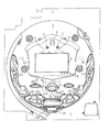
図1に示すように、パチンコ遊技機1は、額縁状に形成されたガラス扉枠2を有する。ガラス扉枠2の下部表面には打球供給皿(上皿)3がある。打球供給皿3の下部には、打球供給皿3に収容しきれない遊技球を貯留する余剰球受皿4と遊技球を発射する打球操作ハンドル(操作ノブ)5が設けられている。ガラス扉枠2の背面には、遊技盤6が着脱可能に取り付けられている。なお、遊技盤6は、それを構成する板状体と、その板状体に取り付けられた種々の部品とを含む構造体である。また、遊技盤6の前面には遊技領域7が形成されている。
As shown in FIG. 1, the
遊技領域7の中央付近には、それぞれが演出用の飾り図柄(演出図柄)を可変表示する複数の可変表示部を含む演出表示装置(飾り図柄表示装置)9が設けられている。演出表示装置9には、例えば「左」、「中」、「右」の3つの可変表示部(図柄表示エリア)がある。演出表示装置9は、特別図柄表示器8による特別図柄の可変表示期間中に、装飾用(演出用)の図柄としての演出図柄の可変表示を行う。演出図柄の可変表示を行う演出表示装置9は、演出制御基板に搭載されている演出制御用マイクロコンピュータによって制御される。
In the vicinity of the center of the
演出表示装置9の下部には、始動入賞口14に入った有効入賞球数すなわち保留記憶(始動記憶または始動入賞記憶ともいう。)数を表示する4つの特別図柄保留記憶表示器18が設けられている。特別図柄保留記憶表示器18は、保留記憶数を入賞順に4個まで表示する。特別図柄保留記憶表示器18は、始動入賞口14に始動入賞があるごとに、点灯状態のLEDの数を1増やす。そして、特別図柄保留記憶表示器18は、特別図柄表示器8で可変表示が開始されるごとに、点灯状態のLEDの数を1減らす(すなわち1つのLEDを消灯する)。具体的には、特別図柄保留記憶表示器18は、特別図柄表示器8で可変表示が開始されるごとに、点灯状態をシフトする。なお、この例では、始動入賞口14への入賞による始動記憶数に上限数(4個まで)が設けられているが、上限数を4個以上にしてもよい。
Below the
演出表示装置9の上部には、識別情報としての特別図柄を可変表示する特別図柄表示器(特別図柄表示装置)8が設けられている。この実施の形態では、特別図柄表示器8は、例えば0〜9の数字を可変表示可能な簡易で小型の表示器(例えば7セグメントLED)で実現されている。特別図柄表示器8は、遊技者に特定の停止図柄を把握しづらくさせるために、0〜99など、より多種類の数字を可変表示するように構成されていてもよい。また、演出表示装置9は、特別図柄表示器8による特別図柄の可変表示期間中に、装飾用(演出用)の図柄としての演出図柄の可変表示を行う。
A special symbol display (special symbol display device) 8 that variably displays a special symbol as identification information is provided on the top of the
演出表示装置9の下方には、始動入賞口14を形成する可変入賞球装置15が設けられている。可変入賞球装置15は、羽根を開閉可能に構成され、羽根が開放しているときに遊技球が入賞し易い状態(開状態)となり、羽根が開放していないとき(閉じているとき)に遊技球が入賞し難い状態(閉状態)となる。始動入賞口14に入った入賞球は、遊技盤6の背面に導かれ、始動口スイッチ14a(例えば、近接スイッチ)によって検出される。また、可変入賞球装置15は、ソレノイド16によって開状態にされる。なお、可変入賞球装置15の真上に第1始動入賞口を設け、可変入賞球装置15を第2始動入賞口としてもよい。
Below the
可変入賞球装置15の下部には、特定遊技状態(大当り状態)においてソレノイド21によって開状態に制御される開閉板を用いた特別可変入賞球装置20が設けられている。特別可変入賞球装置20は大入賞口を開閉する手段である。特別可変入賞球装置20に入賞し遊技盤6の背面に導かれた入賞球は、カウントスイッチ23(例えば、近接スイッチ)で検出される。
Below the variable winning
遊技球がゲート32を通過しゲートスイッチ32aで検出されると、普通図柄表示器10の表示の可変表示が開始される。この実施の形態では、左右のランプ(点灯時に図柄が視認可能になる)が交互に点灯することによって可変表示が行われ、例えば、可変表示の終了時に左側のランプが点灯すれば当りになる。そして、普通図柄表示器10における停止図柄が所定の図柄(当り図柄)である場合に、可変入賞球装置15が所定回数、所定時間だけ開状態になる。普通図柄表示器10の近傍には、ゲート32を通過した入賞球数を表示する4つのLEDによる表示部を有する普通図柄始動記憶表示器41が設けられている。ゲート32への遊技球の通過があるごとに、普通図柄始動記憶表示器41は点灯するLEDを1増やす。そして、普通図柄表示器10の可変表示が開始されるごとに、点灯するLEDを1減らす。
When the game ball passes through the
遊技盤6には、複数の入賞口29,30が設けられ、遊技球の入賞口29,30への入賞は、それぞれ入賞口スイッチ29a,30a(例えば、近接スイッチ)によって検出される。
The
各入賞口29,30は、遊技媒体を受け入れて入賞を許容する領域として遊技盤6に設けられる入賞領域を構成している。なお、始動入賞口14や大入賞口も、遊技媒体を受け入れて入賞を許容する入賞領域を構成する。なお、各入賞口29,30に入賞した遊技球を入賞スイッチで検出する構成に代えて、遊技球が所定領域(例えばゲート)を通過したことを検出スイッチで検出する構成としてもよい。遊技領域7の左右周辺には、遊技中に点滅表示される装飾ランプ25が設けられ、下部には、入賞しなかった遊技球を吸収するアウト口26がある。また、遊技領域7の外側の左右上部には、効果音を発する2つのスピーカ27が設けられている。遊技領域7の外周には、天枠ランプ28a、左枠ランプ28bおよび右枠ランプ28cが設けられている。さらに、遊技領域7における各構造物(大入賞口等)の周囲には装飾LEDが設置されている。天枠ランプ28a、左枠ランプ28bおよび右枠ランプ28cおよび装飾用LEDは、遊技機に設けられている装飾発光体の一例である。なお、この実施の形態では、遊技機に設けられている発光体をランプやLEDを用いて構成する場合を示しているが、この実施の形態で示した態様にかぎらず、例えば、遊技機に設けられている発光体を全てLEDを用いて構成するようにしてもよい。
Each of the winning
なお、図1および図2では、図示を省略しているが、左枠ランプ28bの近傍に、賞球払出中に点灯する賞球ランプが設けられ、天枠ランプ28aの近傍に、補給球が切れたときに点灯する球切れランプが設けられている。なお、賞球ランプおよび球切れランプは、賞球の払出中である場合や球切れが検出された場合に、演出制御基板に搭載された演出制御用マイクロコンピュータによって点灯制御される。さらに、プリペイドカードが挿入されることによって球貸しを可能にするプリペイドカードユニット(以下、「カードユニット」という。)50が、パチンコ遊技機1に隣接して設置されている。
Although not shown in FIGS. 1 and 2, a prize ball lamp that is turned on during the prize ball payout is provided in the vicinity of the
カードユニット50には、例えば、使用可能状態であるか否かを示す使用可表示ランプ、カードユニットがいずれの側のパチンコ遊技機1に対応しているのかを示す連結台方向表示器、カードユニット内にカードが投入されていることを示すカード投入表示ランプ、記録媒体としてのカードが挿入されるカード挿入口、およびカード挿入口の裏面に設けられているカードリーダライタの機構を点検する場合にカードユニットを解放するためのカードユニット錠が設けられている。
The
遊技者の操作により打球発射装置から発射された遊技球は、打球レールを通って遊技領域7に入り、その後、遊技領域7を下りてくる。遊技球が始動入賞口14に入り始動口スイッチ14aで検出されると、図柄の可変表示を開始できる状態であれば、特別図柄表示器8において特別図柄が可変表示(変動)を始める。図柄の可変表示を開始できる状態でなければ、保留記憶数を1増やす。
A game ball launched from the ball striking device by the player's operation enters the
特別図柄表示器8における特別図柄の可変表示は、一定時間が経過したときに停止する。停止時の特別図柄(停止図柄)が大当り図柄(特定表示結果)であると、大当り遊技状態に移行する。すなわち、特別可変入賞球装置20が、一定時間経過するまで、または、所定個数(例えば10個)の遊技球が入賞するまで開放する。そして、特別可変入賞球装置20の開放は、決定されたラウンド数の最後のラウンドまで(例えば、15ラウンドまで)許容される。
The variable display of the special symbol on the special
停止時の特別図柄表示器8における特別図柄が確率変動を伴う大当り図柄(確変図柄)である場合には、次に大当りになる確率が高くなる。すなわち、確変状態という遊技者にとってさらに有利な状態になる。
When the special symbol on the
遊技球がゲート32を通過すると、普通図柄表示器10において普通図柄が可変表示される状態になる。また、普通図柄表示器10における停止図柄が所定の図柄(当り図柄)である場合に、可変入賞球装置15が所定時間だけ開状態になる。
When the game ball passes through the
打球供給皿3を構成する部材においては、遊技者により操作可能な操作手段としての操作ボタン120が設けられている。操作ボタン120には、遊技者が押圧操作をすることが可能な押しボタンスイッチが設けられている。なお、操作ボタン120は、遊技者による押圧操作が可能な押しボタンスイッチが設けられているだけでなく、遊技者による回転操作が可能なダイヤルも設けられている。遊技者は、ダイヤルを回転操作することによって、所定の選択(例えば演出の選択)を行うことができる。
The members constituting the hitting
また、この実施の形態では、遊技領域7のうち始動入賞口14や大入賞口などが設けられている領域の背面には電波センサ61が設けられている。また、この実施の形態では、遊技領域7の所定領域の背面には磁石センサ62が設けられている。なお、図1に示した電波センサ61や磁石センサ62の数や配置は一例であり、遊技領域7の構成の仕方などによって電波センサ61や磁石センサ62を様々な数・位置に配置してもよい。例えば、電波センサ61や磁石センサ62は、遊技機の裏面(例えば入賞口に対応した背面位置や、演出制御基板上や遊技制御基板上)以外に遊技機の表面や遊技機盤面ではなく遊技機枠に設けられていてもよい。図1に示すように、この実施の形態では、電波センサ61が設けられていることによって電波を用いて不正に入賞を誤検出させるような行為を検出できるとともに、磁石センサ62が設けられていることによって磁石を用いて不正に遊技球を入賞口に誘導させるような行為を検出することができる。
In this embodiment, a radio wave sensor 61 is provided on the back side of the
次に、パチンコ遊技機1の裏面の構造について図3を参照して説明する。図3は、遊技機を裏面から見た背面図である。図3に示すように、パチンコ遊技機1裏面側では、演出表示装置9を制御する演出制御用マイクロコンピュータ100が搭載された演出制御基板80を含む変動表示制御ユニット、遊技制御用マイクロコンピュータ等が搭載された遊技制御基板(主基板)31、音声出力基板70、ランプドライバ基板35、および球払出制御を行う払出制御用マイクロコンピュータ等が搭載された払出制御基板37等の各種基板が設置されている。なお、遊技制御基板31は基板収納ケース200に収納されている。また、演出制御基板80および遊技制御基板(主基板)31には、裏面側から見て視認可能な態様でそれぞれエラー報知用LED80A,31Aが設けられている。
Next, the structure of the back surface of the
さらに、パチンコ遊技機1裏面側には、DC30V、DC21V、DC12VおよびDC5V等の各種電源電圧を作成する電源回路が搭載された電源基板910やタッチセンサ基板91が設けられている。電源基板910には、パチンコ遊技機1における遊技制御基板31および各電気部品制御基板(演出制御基板80および払出制御基板37)やパチンコ遊技機1に設けられている各電気部品(電力が供給されることによって動作する部品)への電力供給を実行あるいは遮断するための電力供給許可手段としての電源スイッチ、遊技制御基板31の遊技制御用マイクロコンピュータ560のRAM55をクリアするためのクリアスイッチが設けられている。さらに、電源スイッチの内側(基板内部側)には、交換可能なヒューズが設けられている。
Further, on the back side of the
なお、この実施の形態では、主基板31は遊技盤側に設けられ、払出制御基板37は遊技枠側に設けられている。このような構成であっても、後述するように、主基板31と払出制御基板37との間の通信をシリアル通信で行うことによって、遊技盤を交換する際の配線の取り回しを容易にしている。
In this embodiment, the
なお、各制御基板には、制御用マイクロコンピュータを含む制御手段が搭載されている。制御手段は、遊技制御手段等からのコマンドとしての指令信号(制御信号)に従って遊技機に設けられている電気部品(遊技用装置:球払出装置97、演出表示装置9、ランプやLEDなどの発光体、スピーカ27等)を制御する。以下、主基板31を制御基板に含めて説明を行うことがある。その場合には、制御基板に搭載される制御手段は、遊技制御手段と、遊技制御手段等からの指令信号に従って遊技機に設けられている電気部品を制御する手段とのそれぞれを指す。また、主基板31以外のマイクロコンピュータが搭載された基板をサブ基板ということがある。なお、球払出装置97は、遊技球を誘導する通路とステッピングモータ等により駆動されるスプロケット等によって誘導された遊技球を上皿や下皿に払い出すための装置であって、払い出された賞球や貸し球をカウントする払出個数カウントスイッチ等もユニットの一部として構成されている。なお、この実施の形態では、払出検出手段は、払出個数カウントスイッチ301によって実現され、球払出装置97から実際に賞球や貸し球が払い出されたことを検出する機能を備える。この場合、払出個数カウントスイッチ301は、賞球や貸し球の払い出しを1球検出するごとに検出信号を出力する。
Each control board is equipped with control means including a control microcomputer. The control means is an electrical component (game device:
パチンコ遊技機1裏面において、上方には、各種情報をパチンコ遊技機1の外部に出力するための各端子を備えたターミナル基板160が設置されている。ターミナル基板160には、例えば、大当り遊技状態の発生を示す大当り情報等の情報出力信号(図17に示す図柄確定回数1信号、始動口信号、大当り1信号、大当り2信号、大当り3信号、時短信号、入賞信号、セキュリティ信号、高確中信号、賞球情報)を外部出力するための情報出力端子が設けられている。
On the back side of the
貯留タンク38に貯留された遊技球は誘導レール(図示せず)を通り、カーブ樋を経て払出ケース40Aで覆われた球払出装置97に至る。球払出装置97の上方には、遊技媒体切れ検出手段としての球切れスイッチ187が設けられている。球切れスイッチ187が球切れを検出すると、球払出装置97の払出動作が停止する。球切れスイッチ187は遊技球通路内の遊技球の有無を検出するスイッチであるが、貯留タンク38内の補給球の不足を検出する球切れ検出スイッチ167も誘導レールにおける上流部分(貯留タンク38に近接する部分)に設けられている。球切れ検出スイッチ167が遊技球の不足を検知すると、遊技機設置島に設けられている補給機構からパチンコ遊技機1に対して遊技球の補給が行なわれる。
The game ball stored in the
入賞にもとづく景品としての遊技球や球貸し要求にもとづく遊技球が多数払出されて打球供給皿3が満杯になると、遊技球は、余剰球誘導通路を経て余剰球受皿4に導かれる。さらに遊技球が払出されると、感知レバー(図示せず)が貯留状態検出手段としての満タンスイッチを押圧して、貯留状態検出手段としての満タンスイッチがオンする。その状態では、球払出装置内の払出モータの回転が停止して球払出装置の動作が停止するとともに打球発射装置の駆動も停止する。
When a large number of game balls as prizes based on winning a prize or a game ball based on a ball lending request are paid out and the hitting
図4は、主基板(遊技制御基板)31における回路構成の一例を示すブロック図である。なお、図4には、払出制御基板37および演出制御基板80等も示されている。主基板31には、プログラムに従ってパチンコ遊技機1を制御する遊技制御用マイクロコンピュータ(遊技制御手段に相当)560、制御用クロック生成回路111、および乱数用クロック生成回路112が搭載されている。遊技制御用マイクロコンピュータ560は、ゲーム制御(遊技進行制御)用のプログラム等を記憶するROM54、ワークメモリとして使用される記憶手段としてのRAM55、プログラムに従って制御動作を行うCPU56およびI/Oポート部57を含む。この実施の形態では、ROM54およびRAM55は遊技制御用マイクロコンピュータ560に内蔵されている。すなわち、遊技制御用マイクロコンピュータ560は、1チップマイクロコンピュータである。1チップマイクロコンピュータには、少なくともRAM55が内蔵されていればよく、ROM54は外付けであっても内蔵されていてもよい。また、I/Oポート部57は、外付けであってもよい。さらに、ハードウェア乱数(ハードウェア回路が発生する乱数)を発生する乱数回路509が内蔵されている。
FIG. 4 is a block diagram showing an example of the circuit configuration of the main board (game control board) 31. FIG. 4 also shows a
ここで、制御用クロック生成回路111は、遊技制御用マイクロコンピュータ560の外部にて、所定周波数の発振信号となる制御用クロックCCLKを生成する。制御用クロック生成回路111により生成された制御用クロックCCLKは、例えば、遊技制御用マイクロコンピュータ560の制御用外部クロック端子EXCを介してクロック回路502に供給される。乱数用クロック生成回路112は、遊技制御用マイクロコンピュータ560の外部にて、制御用クロックCCLKの発振周波数とは異なる所定周波数の発振信号となる乱数用クロックRCLKを生成する。乱数用クロック生成回路112により生成された乱数用クロックRCLKは、例えば、遊技制御用マイクロコンピュータ560の乱数用外部クロック端子ERCを介して乱数回路509に供給される。一例として、乱数用クロック生成回路112により生成される乱数用クロックRCLKの発振周波数は、制御用クロック生成回路111により生成される制御用クロックCCLKの発振周波数以下となるようにすればよい。あるいは、乱数用クロック生成回路112により生成される乱数用クロックRCLKの発振周波数は、制御用クロック生成回路111により生成される制御用クロックCCLKの発振周波数よりも高周波となるようにしてもよい。
Here, the control
なお、遊技制御用マイクロコンピュータ560においてCPU56がROM54に格納されているプログラムに従って制御を実行するので、以下、遊技制御用マイクロコンピュータ560(またはCPU56)が実行する(または、処理を行う)ということは、具体的には、CPU56がプログラムに従って制御を実行することである。このことは、主基板31以外の他の基板に搭載されているマイクロコンピュータについても同様である。
In the
遊技制御用マイクロコンピュータ560は、始動口スイッチ14aへの始動入賞が生じたときに乱数回路509から数値データをランダムRとして読み出し、特別図柄および演出図柄の変動開始時にランダムRにもとづいて特定の表示結果としての大当り表示結果にするか否か、すなわち、大当りとするか否かを決定する。そして、大当りとすると決定したときに、遊技状態を遊技者にとって有利な特定遊技状態としての大当り遊技状態に移行させる。
The
また、遊技制御用マイクロコンピュータ560には、払出制御基板37(の払出制御用マイクロコンピュータ370)とシリアル通信で信号を入出力(送受信)するためのシリアル通信回路511が内蔵されている。なお、払出制御用マイクロコンピュータ370にも、遊技制御用マイクロコンピュータ560とシリアル通信で信号を入出力するためのシリアル通信回路が内蔵されている。
The
なお、この実施の形態では、遊技制御用マイクロコンピュータ560と払出制御用マイクロコンピュータ370との間でシリアル通信を行う場合を示しているが、演出制御基板80側にもシリアル通信回路を搭載するようにし、遊技制御用マイクロコンピュータ560は、シリアル通信方式を用いて演出制御コマンドを演出制御用マイクロコンピュータ100に送信するように制御してもよい。
In this embodiment, serial communication is performed between the
また、RAM55は、その一部または全部が電源基板において作成されるバックアップ電源によってバックアップされている不揮発性記憶手段としてのバックアップRAMである。すなわち、遊技機に対する電力供給が停止しても、所定期間(バックアップ電源としてのコンデンサが放電してバックアップ電源が電力供給不能になるまで)は、RAM55の一部または全部の内容は保存される。特に、少なくとも、遊技状態すなわち遊技制御手段の制御状態に応じたデータ(特別図柄プロセスフラグや、保留記憶数をカウントするための保留記憶数カウンタの値など)と未払出賞球数を示すデータ(具体的には、後述する賞球コマンド出力カウンタの値)は、バックアップRAMに保存される。遊技制御手段の制御状態に応じたデータとは、停電等が生じた後に復旧した場合に、そのデータにもとづいて、遊技を再開させるために必要なデータである。また、制御状態に応じたデータと未払出賞球数を示すデータとを遊技の進行状態を示すデータと定義する。また、この実施の形態では、バックアップRAMには、後述する磁気異常を検出したことを示す磁気異常フラグや、セキュリティ信号を出力するために用いるセキュリティ信号情報タイマも保存される。 The RAM 55 is a backup RAM as a non-volatile storage means, part or all of which is backed up by a backup power supply created on the power supply board. That is, even if the power supply to the gaming machine is stopped, a part or all of the contents of the RAM 55 is stored for a predetermined period (until the capacitor as the backup power supply is discharged and the backup power supply cannot be supplied). In particular, at least data corresponding to the game state, that is, the control state of the game control means (a special symbol process flag, a value of a reserved memory number counter for counting the number of reserved memories) and data indicating the number of unpaid winning balls ( Specifically, a value of a prize ball command output counter (to be described later) is stored in the backup RAM. The data corresponding to the control state of the game control means is data necessary for resuming the game based on the data when the power is restored after a power failure or the like occurs. Further, data corresponding to the control state and data indicating the number of unpaid prize balls are defined as data indicating the progress state of the game. In this embodiment, the backup RAM also stores a magnetic abnormality flag indicating that a magnetic abnormality described later has been detected, and a security signal information timer used for outputting a security signal.
遊技制御用マイクロコンピュータ560のリセット端子には、電源基板からのリセット信号が入力される。電源基板には、遊技制御用マイクロコンピュータ560等に供給されるリセット信号を生成するリセット回路が搭載されている。なお、リセット信号がハイレベルになると遊技制御用マイクロコンピュータ560等は動作可能状態になり、リセット信号がローレベルになると遊技制御用マイクロコンピュータ560等は動作停止状態になる。従って、リセット信号がハイレベルである期間は、遊技制御用マイクロコンピュータ560等の動作を許容する許容信号が出力されていることになり、リセット信号がローレベルである期間は、遊技制御用マイクロコンピュータ560等の動作を停止させる動作停止信号が出力されていることになる。なお、リセット回路をそれぞれの電気部品制御基板(電気部品を制御するためのマイクロコンピュータが搭載されている基板)に搭載してもよい。
A reset signal from the power supply board is input to the reset terminal of the
さらに、遊技制御用マイクロコンピュータ560の入力ポートには、電源基板からの電源電圧が所定値以下に低下したことを示す電源断信号が入力される。すなわち、電源基板には、遊技機において使用される所定電圧(例えば、DC30VやDC5Vなど)の電圧値を監視して、電圧値があらかじめ定められた所定値にまで低下すると(電源電圧の低下を検出すると)、その旨を示す電源断信号を出力する電源監視回路が搭載されている。なお、電源監視回路を電源基板に搭載するのではなく、バックアップ電源によって電源バックアップされる基板(例えば、主基板31)に搭載するようにしてもよい。また、遊技制御用マイクロコンピュータ560の入力ポートには、RAMの内容をクリアすることを指示するためのクリアスイッチが操作されたことを示すクリア信号(図示せず)が入力される。
Further, a power-off signal indicating that the power supply voltage from the power supply board has dropped below a predetermined value is input to the input port of the
また、ゲートスイッチ32a、始動口スイッチ14a、カウントスイッチ23、および各入賞口スイッチ29a,30aからの検出信号を基本回路53に与える入力ドライバ回路58も主基板31に搭載され、可変入賞球装置15を開閉するソレノイド16、および特別可変入賞球装置を開閉するソレノイド21を基本回路53からの指令に従って駆動する出力回路59も主基板31に搭載され、電源投入時に遊技制御用マイクロコンピュータ560をリセットするためのシステムリセット回路(図示せず)や、大当り遊技状態の発生を示す大当り情報等の情報出力信号を、ターミナル基板160を介して、ホールコンピュータ等の外部装置に対して出力する情報出力回路64も主基板31に搭載されている。
Also, an input driver circuit 58 for supplying the basic circuit 53 with detection signals from the
また、遊技制御用マイクロコンピュータ560は、特別図柄を可変表示する特別図柄表示器8、普通図柄を可変表示する普通図柄表示器10、特別図柄保留記憶表示器18および普通図柄保留記憶表示器41の表示制御を行う。また、遊技制御用マイクロコンピュータ560は、エラー報知用LED31Aの点灯制御を行う。
In addition, the
この実施の形態では、演出制御基板80に搭載されている演出制御手段(演出制御用マイクロコンピュータで構成される。)が、中継基板77を介して遊技制御用マイクロコンピュータ560からの演出制御コマンドを受信し、演出図柄を可変表示する演出表示装置9の表示制御を行う。
In this embodiment, the effect control means (configured by the effect control microcomputer) mounted on the
図5は、中継基板77、演出制御基板80、ランプドライバ基板35および音声出力基板70の回路構成例を示すブロック図である。なお、図5に示す例では、ランプドライバ基板35および音声出力基板70には、マイクロコンピュータは搭載されていないが、マイクロコンピュータを搭載してもよい。また、ランプドライバ基板35および音声出力基板70を設けずに、演出制御に関して演出制御基板80のみを設けてもよい。
FIG. 5 is a block diagram illustrating a circuit configuration example of the
演出制御基板80は、演出制御用CPU101、および演出図柄プロセスフラグ等の演出に関する情報を記憶するRAMを含む演出制御用マイクロコンピュータ100を搭載している。なお、RAMは外付けであってもよい。この実施の形態では、演出制御用マイクロコンピュータ100におけるRAMは電源バックアップされていない。演出制御基板80において、演出制御用CPU101は、内蔵または外付けのROM(図示せず)に格納されたプログラムに従って動作し、中継基板77を介して入力される主基板31からの取込信号(演出制御INT信号)に応じて、入力ドライバおよび入力ポート(図示省略)を介して演出制御コマンドを受信する。また、演出制御用CPU101は、演出制御コマンドにもとづいて、VDP(ビデオディスプレイプロセッサ)109に演出表示装置9の表示制御を行わせる。
The
この実施の形態では、演出制御用マイクロコンピュータ100と共動して演出表示装置9の表示制御を行うVDP109が演出制御基板80に搭載されている。VDP109は、演出制御用マイクロコンピュータ100とは独立したアドレス空間を有し、そこにVRAMをマッピングする。VRAMは、画像データを展開するためのバッファメモリである。そして、VDP109は、VRAM内の画像データをフレームメモリを介して演出表示装置9に出力する。
In this embodiment, a
演出制御用CPU101は、受信した演出制御コマンドに従ってCGROM(図示せず)から必要なデータを読み出すための指令をVDP109に出力する。CGROMは、演出表示装置9に表示されるキャラクタ画像データや動画像データ、具体的には、人物、文字、図形や記号等(演出図柄を含む)、および背景画像のデータをあらかじめ格納しておくためのROMである。VDP109は、演出制御用CPU101の指令に応じて、CGROMから画像データを読み出す。そして、VDP109は、読み出した画像データにもとづいて表示制御を実行する。
The
さらに、演出制御用CPU101は、出力ポート105を介してランプドライバ基板35に対してランプを駆動する信号を出力する。また、演出制御用CPU101は、出力ポート104を介して音声出力基板70に対して音番号データを出力する。
Further, the
ランプドライバ基板35において、ランプを駆動する信号は、入力ドライバ351を介してランプドライバ352に入力される。ランプドライバ352は、ランプを駆動する信号にもとづいて天枠ランプ28a、左枠ランプ28bおよび右枠ランプ28cなどの枠側に設けられている発光体に電流を供給する。また、遊技盤側に設けられている装飾ランプ25に電流を供給する。
In the lamp driver board 35, a signal for driving the lamp is input to the
音声出力基板70において、音番号データは、入力ドライバ702を介して音声合成用IC703に入力される。音声合成用IC703は、音番号データに応じた音声や効果音を発生し増幅回路705に出力する。増幅回路705は、音声合成用IC703の出力レベルを、ボリューム706で設定されている音量に応じたレベルに増幅した音声信号をスピーカ27に出力する。音声データROM704には、音番号データに応じた制御データが格納されている。音番号データに応じた制御データは、所定期間(例えば演出図柄の変動期間)における効果音または音声の出力態様を時系列的に示すデータの集まりである。
In the
また、演出制御用CPU101は、入力ポート106を介して、遊技者による操作ボタン120の押圧操作に応じて操作ボタン120からの信号を入力する。また、演出制御用CPU101は、出力ポート105を介してエラー報知用LED80Aの点灯制御を行う。
Further, the
図6は、遊技制御手段における出力ポートの割り当ての例を示す説明図である。図6に示すように、出力ポート0からは、払出制御基板37に送信される払出制御信号(本例では、接続信号)が出力される。また、大入賞口を開閉する可変入賞球装置20を開閉するためのソレノイド(大入賞口扉ソレノイド)21、および可変入賞球装置15を開閉するためのソレノイド(普通電動役物ソレノイド)16に対する駆動信号も、出力ポート0から出力される。また、出力ポート0から、ターミナル基板160を介して外部装置(例えば、ホールコンピュータ)に対して出力される信号のうち高確中信号も出力される。
FIG. 6 is an explanatory diagram showing an example of output port assignment in the game control means. As shown in FIG. 6, a payout control signal (in this example, a connection signal) transmitted to the
なお、図6に示された「論理」(例えば1がオン状態)と逆の論理(例えば0がオン状態)を用いてもよいが、特に、接続信号については、主基板31と払出制御基板37との間の信号線において断線が生じた場合やケーブル外れの場合(ケーブル未接続を含む)等に、払出制御用マイクロコンピュータ370では必ずオフ状態と検知されるように「論理」が定められる。具体的には、一般に、断線やケーブル外れが生ずると信号の受信側ではハイレベルが検知されるので、主基板31と払出制御基板37との間の信号線でのハイレベルが、遊技制御手段における出力ポートにおいてオフ状態になるように「論理」が定められる。従って、必要であれば、主基板31において出力ポートの外側に、信号を論理反転させる出力バッファ回路が設置される。
Note that the logic (for example, 0 is on) opposite to the “logic” (for example, 1 is on) shown in FIG. 6 may be used. In particular, for the connection signal, the
そして、出力ポート1から、ターミナル基板160を介して、外部装置(例えば、ホールコンピュータ)に対して、各種情報出力用信号すなわち制御に関わる情報(例えば、図柄確定回数1信号、始動口信号、大当り1信号、大当り2信号、大当り3信号、時短信号、入賞信号、セキュリティ信号)の出力データが出力される。ただし、既に説明したように、外部出力される信号のうち高確中信号については、出力ポート0から出力される。なお、この実施の形態では、賞球情報(賞球払出を10個検出するごとに出力される信号)も、ターミナル基板160を介して外部装置に出力される。この場合、払出制御基板37側において、賞球払出が検出され、賞球情報が主基板31に入力される。そして、主基板31に入力された賞球情報は、遊技制御用マイクロコンピュータ560を経由することなく、主基板31上をそのまま経由してターミナル基板160を介して外部出力される。なお、主基板31に入力された賞球情報は、遊技制御用マイクロコンピュータ560を一旦経由してから、ターミナル基板160を介して外部出力されるようにしてもよい。
From the
なお、ターミナル基板160を介して外部出力される信号は、この実施の形態で示したものに限られない。例えば、遊技枠が開放状態であることを示すドア開放信号や、賞球信号1(賞球払出を1個検出するごとに出力される信号)、遊技機エラー状態信号(遊技機がエラー状態(本例では、球切れエラー状態または満タンエラー状態)であることを示す信号)も、ターミナル基板160を介して外部装置に出力されるようにしてもよい。この場合、払出制御基板37側において、遊技枠が開放状態であることや、賞球払出、遊技機のエラー状態も検出され、ドア開放信号や賞球信号1、遊技機エラー状態信号が主基板31に入力される。そして、主基板31に入力されたドア開放信号や賞球信号1、遊技機エラー状態信号は、遊技制御用マイクロコンピュータ560を経由することなく、主基板31上をそのまま経由してターミナル基板160を介して外部出力される。なお、この場合も、主基板31に入力されたドア開放信号や賞球信号1、遊技機エラー状態信号は、遊技制御用マイクロコンピュータ560を一旦経由してから、ターミナル基板160を介して外部出力されるようにしてもよい。
Note that signals output to the outside via the
また、例えば、特別図柄表示装置を2つ備えるように遊技機を構成する場合、特別図柄の変動回数を通知するための図柄確定回数信号として図柄確定回数1信号に加えて図柄確定回数2信号も、ターミナル基板160を介して外部出力するようにしてもよい。この場合、例えば、いずれか一方の特別図柄の変動回数のみを通知するための信号として図柄確定回数2信号を外部出力するようにし、両方の特別図柄の変動回数を通知するための信号として図柄確定回数1信号を外部出力するように構成すればよい。そのように構成すれば、ホールコンピュータなどの外部装置側において、いずれか一方の特別図柄のみの変動回数に加えて、両方の特別図柄の合計の変動回数も把握することができる。
In addition, for example, when a gaming machine is configured to include two special symbol display devices, a
図7は、遊技制御手段における入力ポートのビット割り当ての例を示す説明図である。図7に示すように、入力ポート0のビット0,2,3には、それぞれ、カウントスイッチ23の検出信号、および入賞口スイッチ29a,30aの検出信号の検出信号が入力される。また、入力ポート1のビット4〜7には、それぞれ、電波センサ信号、磁石センサ信号、ドア開放信号、賞球情報が入力される。また、入力ポート2のビット0,2〜4には、それぞれ、始動口スイッチ14aの検出信号、ゲートスイッチ32aの検出信号、電源基板910からのクリアスイッチの検出信号および電源断信号が入力される。
FIG. 7 is an explanatory diagram showing an example of bit assignment of input ports in the game control means. As shown in FIG. 7, the detection signals of the
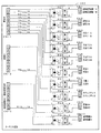
図8は、ターミナル基板160の内部構成を示す回路図である。図8に示すターミナル基板160において、左側上段のコネクタCN−1,CN−2は、主基板31からの信号を伝達するケーブルを接続するためのコネクタであり、左側下段のコネクタCN−3は、払出制御基板37からの信号を、主基板31を経由して伝達するケーブルを接続するためのコネクタである。また、右側のコネクタCN1〜CN10は、ホールコンピュータなど外部装置に対して信号を伝達するケーブルを接続するためのコネクタである。また、ターミナル基板160には、ドライバ回路としての半導体リレー(PhotoMOSリレー)PC1〜PC10が搭載されている。
FIG. 8 is a circuit diagram showing an internal configuration of the
主基板31からのケーブルがコネクタCN−1,CN−2に接続されることにより、主基板31(遊技制御用マイクロコンピュータ560)から各種信号がターミナル基板160に入力される。具体的には、コネクタCN−1の端子「2」に図柄確定回数1信号が入力され、コネクタCN−1の端子「3」に始動口信号が入力され、コネクタCN−1の端子「4」に大当り1信号が入力され、コネクタCN−1の端子「5」に大当り2信号が入力され、コネクタCN−1の端子「6」に大当り3信号が入力され、コネクタCN−1の端子「7」に時短信号が入力され、コネクタCN−1の端子「8」に入賞信号が入力され、コネクタCN−1の端子「9」にセキュリティ信号が入力され、コネクタCN−2の端子「9」に高確中信号が入力される。
When the cable from the
また、払出制御基板37からのケーブルが主基板31を経由してコネクタCN−3に接続されることにより、払出制御基板37(払出制御用マイクロコンピュータ370)からの信号がターミナル基板160に入力される。具体的には、コネクタCN−3の端子「9」に賞球情報が入力される。
Further, when the cable from the
図8に示すように、ターミナル基板160では、コネクタCN−1、コネクタCN−2およびコネクタCN−3の端子「1」に基準電位の信号線が接続され、その信号線が分岐して、各々の半導体リレーPC1〜PC10の入力端子「1」に接続されている。また、コネクタCN−1の端子「2」〜「9」、コネクタCN−2のコネクタ「9」、およびコネクタCN−3のコネクタ「9」に接続された信号線は、それぞれ、1KΩの抵抗R1〜R10を介して半導体リレーPC1〜PC10の入力端子「2」に接続されている。また、半導体リレーPC1〜PC10の出力端子「4」に接続された信号線は、それぞれ、コネクタCN1〜CN10の端子「1」に接続されている。また、半導体リレーPC1〜PC10の出力端子「3」に接続された信号線は、それぞれ、コネクタCN1〜CN10の端子「2」に接続されている。
As shown in FIG. 8, in the
半導体リレーPC1〜PC10では、入力端子に信号電流が流れると、入力側の発光素子(LED)が発光する。発光された光は、LEDと対向に設けられた光電素子(太陽電池)に透明シリコンを通って照射される。光を受けた光電素子は、光の量に応じて電圧に交換し、この電圧は制御回路を通って出力部のMOSFETゲートを充電する。光電素子より供給されるMOSFETゲート電圧が設定電圧値に達すると、MOSFETが導通状態になり、負荷をオンさせる。入力端子の信号電流が切れると、発光素子(LED)の発光が止まる。LEDの発光が止まると、光電素子の電圧が下がり、光電素子から供給される電圧が下がると制御回路により、MOSFETのゲート負荷を急速に放電させる。この制御回路によりMOSFETが非導通状態になり、負荷をオフさせる。 In the semiconductor relays PC1 to PC10, when a signal current flows through the input terminal, the light emitting element (LED) on the input side emits light. The emitted light is applied to the photoelectric element (solar cell) provided opposite to the LED through the transparent silicon. The photoelectric element that has received the light is exchanged for voltage according to the amount of light, and this voltage passes through the control circuit to charge the MOSFET gate of the output section. When the MOSFET gate voltage supplied from the photoelectric element reaches the set voltage value, the MOSFET becomes conductive and turns on the load. When the signal current at the input terminal is cut off, the light emitting element (LED) stops emitting light. When the light emission of the LED stops, the voltage of the photoelectric element decreases, and when the voltage supplied from the photoelectric element decreases, the gate load of the MOSFET is rapidly discharged by the control circuit. With this control circuit, the MOSFET is turned off and the load is turned off.
以上のような半導体リレーPC1〜PC10の動作により、入力側のコネクタCN−1、コネクタCN−2およびコネクタCN−3から入力された信号が出力側のコネクタCN1〜CN10に伝達され、ホールコンピュータなど外部装置に対して出力される。具体的には、コネクタCN1から図柄確定回数1信号が出力され、コネクタCN2から始動口信号が出力され、コネクタCN3から大当り1信号が出力され、コネクタCN4から大当り2信号が出力され、コネクタCN5から大当り3信号が出力され、コネクタCN6から時短信号が出力され、コネクタCN7から入賞信号が出力され、コネクタCN8からセキュリティ信号が出力され、コネクタCN9から高確中信号が出力され、コネクタCN10から賞球情報が出力される。なお、ターミナル基板160における各外部出力信号に対するコネクタの割り当ては、この実施の形態で示したものにかぎられない。例えば、セキュリティ信号については、ターミナル基板160に設けられた一番端のコネクタ(例えば、コネクタCN10)から出力されるようにしてもよい。
By the operation of the semiconductor relays PC1 to PC10 as described above, signals input from the input side connector CN-1, connector CN-2, and connector CN-3 are transmitted to the output side connectors CN1 to CN10, and a hall computer or the like. Output to an external device. Specifically, the
なお、コネクタCN7から出力される入賞信号は、所定数分(この実施の形態では、10個分)の賞球を払い出すための所定の払出条件が成立したこと(始動入賞口14、大入賞口、普通入賞口29,30への入賞が発生したこと。賞球の払出までは行われていない。具体的には、近接スイッチ(入賞口スイッチ29a,30a、カウントスイッチ23、始動口スイッチ14a)からの検出信号を入力したことを条件として、所定の払出条件が成立したと判定されたこと。)を示す信号である。入賞信号を確認することによって、払い出される賞球数の予定数を、ホールコンピュータなどの外部装置側で認識できるようにすることができる。
The winning signal output from the connector CN7 indicates that a predetermined payout condition for paying out a predetermined number (in this embodiment, 10 balls) of winning balls is satisfied (start winning
また、コネクタCN10から出力される賞球情報は、特定数(この実施の形態では、10個)の賞球が払い出されたこと(球払出装置97が駆動されて実際に賞球が払い出されたこと)を示す信号である。賞球情報を確認することによって、実際に払い出された賞球数を、ホールコンピュータなどの外部装置側で認識できるようにすることができる。また、入賞信号で示される賞球の予定数と賞球情報で示される払出済みの賞球数とを確認することによって、賞球払出が正常に行われたか否かや賞球過不足数を、ホールコンピュータなどの外部装置側で認識できるようにすることができる。
Also, the prize ball information output from the connector CN10 is that a specific number (10 balls in this embodiment) of prize balls has been paid out (the
また、コネクタCN8から出力されるセキュリティ信号は、遊技機のセキュリティ状態を示す信号である。具体的には、後述するように、磁石センサ62の検出結果にもとづいて磁気異常が発生したと判定された場合に、セキュリティ信号がホールコンピュータなどの外部装置に出力される。そのように構成することによって、磁石を用いて不正に遊技球を入賞口に誘導させるような不正行為が行われたことを、ホールコンピュータなどの外部装置側で認識できるようにすることができる。
The security signal output from the connector CN8 is a signal indicating the security state of the gaming machine. Specifically, as will be described later, when it is determined that a magnetic abnormality has occurred based on the detection result of the
この実施の形態では、磁気異常の発生にもとづきセキュリティ信号を外部出力する場合には、遊技機への電源が再投入され初期化処理が実行されるまで、この磁気異常の発生にもとづくセキュリティ信号の外部出力が継続される。なお、後述するように、初期化処理が行われた場合にはセキュリティ信号が所定期間(例えば、0.2秒間)外部出力されるので、より正確には、遊技機への電源が再投入され初期化処理が実行されたときに、内部的には磁気異常の発生にもとづくセキュリティ信号の外部出力を終了し、初期化処理にもとづくセキュリティ信号の外部出力が開始され、所定期間(例えば、0.2秒間)を経過するまでセキュリティ信号の出力が継続される。従って、見た目上は、磁気異常の発生にもとづきセキュリティ信号の外部出力が開始された場合には、遊技機への電源が再投入され初期化処理が実行された後、所定期間(例えば、0.2秒間)を経過したときにセキュリティ信号の外部出力が終了する。 In this embodiment, when the security signal is output externally based on the occurrence of the magnetic abnormality, the security signal based on the occurrence of the magnetic abnormality is not replayed until the game machine is turned on again and the initialization process is executed. External output continues. As will be described later, when the initialization process is performed, the security signal is externally output for a predetermined period (for example, 0.2 seconds), and more precisely, the power to the gaming machine is turned on again. When the initialization process is executed, the external output of the security signal based on the occurrence of the magnetic abnormality is terminated internally, and the external output of the security signal based on the initialization process is started for a predetermined period (for example, 0. The output of the security signal is continued until 2 seconds). Therefore, apparently, when external output of a security signal is started based on the occurrence of a magnetic abnormality, the power to the gaming machine is turned on again and the initialization process is executed, and then a predetermined period (for example, 0. 0). The external output of the security signal ends when 2 seconds) elapses.
また、この実施の形態では、電波センサ61の検出結果にもとづいて電波異常が発生したと判定された場合に、セキュリティ信号が所定期間(例えば、0.2秒間)ホールコンピュータなどの外部装置に出力される。そのように構成することによって、電波を用いて不正に入賞を誤検出させるような不正行為が行われたことを、ホールコンピュータなどの外部装置側で認識できるようにすることができる。 In this embodiment, when it is determined that a radio wave abnormality has occurred based on the detection result of the radio wave sensor 61, a security signal is output to an external device such as a hall computer for a predetermined period (for example, 0.2 seconds). Is done. With such a configuration, it is possible to recognize on the side of an external device such as a hall computer that a fraudulent act that erroneously misdetects a prize using radio waves is performed.
また、この実施の形態では、可変入賞球装置15が開状態でないときに始動入賞口14への遊技球の入賞を検出した場合や、大当り遊技中でないときに大入賞口への遊技球の入賞を検出した場合に異常入賞が発生したと判定され、この異常入賞が検出された場合にも、セキュリティ信号が所定期間(例えば、0.2秒間)ホールコンピュータなどの外部装置に出力される。そのように構成することによって、可変入賞球装置15や大入賞口に対する不正行為によって異常入賞が生じたことを報知することができ、その結果、可変入賞球装置15や大入賞口に対する不正行為を確実に防止することができる。
Further, in this embodiment, when a winning of the game ball to the start winning
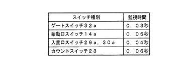
また、この実施の形態では、始動口スイッチ14a、カウントスイッチ23、入賞口スイッチ29a,30aまたはゲートスイッチ32aにおいて、遊技球の入賞を検出した時点から所定の監視期間を経過するまでに遊技球の通過を再度検出した回数が所定回数となった場合や、遊技球の入賞を検出している状態が所定期間継続した場合に異常入賞が発生したと判定され、この異常入賞が検出された場合にも、セキュリティ信号が所定期間(例えば、0.2秒間)ホールコンピュータなどの外部装置に出力される。遊技球の入賞を検出した時点から所定の監視期間を経過するまでに遊技球の通過を再度検出した回数が所定回数となった場合に異常入賞が発生したと判定することで、例えば、何らかの器具を遊技機内部に侵入させ、始動入賞口等に入賞する遊技球を不正に操作して(例えば、同じ遊技球が何度も繰り返し始動入賞口を通過するように操作して)賞球を払い出させる不正行為や、外部から電波を照射してスイッチを誤作動させることで、遊技球を検出した場合に出力する信号を出力させる不正行為などを検知することができる。そのように構成することによって、各種スイッチに対する不正行為によって異常入賞が生じたことを報知することができ、その結果、各種スイッチに対する不正行為を確実に防止することができる。また、遊技球の入賞を検出している状態が所定期間継続した場合に異常入賞が発生したと判定することで、例えば、始動入賞口で球詰まりが発生していることを検知することができる。そのように構成することによって、各種スイッチにおいて球詰まりによって異常が生じたことを報知することができ、その結果、各種スイッチにおける球詰まりを検知することができる。
Further, in this embodiment, the game opening of the game ball from the time when the winning opening of the game ball is detected in the start opening switch 14a, the
また、この実施の形態では、遊技機への電源投入が行われて初期化処理が実行された場合にも、セキュリティ信号が所定期間(例えば、0.2秒間)ホールコンピュータなどの外部装置に出力される。そのように構成することによって、不自然なタイミングで(例えば、遊技店の開店時に全ての遊技機の電源リセット作業を終えた後であるにもかかわらず)初期化処理が実行されたことを認識可能とすることによって、不正に遊技機を電源リセットさせて電源リセットのタイミングで大当りを狙うような不正行為が行われた可能性を、ホールコンピュータなどの外部装置側で認識できるようにすることができる。 In this embodiment, even when the gaming machine is turned on and the initialization process is executed, the security signal is output to an external device such as a hall computer for a predetermined period (for example, 0.2 seconds). Is done. By configuring as such, it is recognized that the initialization process has been executed at an unnatural timing (for example, even after all the gaming machine power reset operations have been completed when the amusement store is opened). By making it possible, the external device such as a hall computer can recognize the possibility that an unauthorized act of illegally resetting the power of the gaming machine and aiming for a big hit at the power reset timing is performed. it can.
なお、この実施の形態では、上記のように、磁気異常が検出された場合と、電波異常が検出された場合と、異常入賞が検出された場合と、初期化処理(例えば、遊技機への電源投入時に、クリアスイッチによる操作が行われたことにもとづいてRAM55の記憶内容をクリアするなどの処理)が実行された場合とで、共通のセキュリティ信号をターミナル基板160の共通のコネクタCN8から外部出力している。これは、初期化処理が実行されるのは、通常、遊技店の開店時に遊技機の電源リセット作業を行う場合のみであることから、1日のうち1回程度しか出力されない信号のためにターミナル基板160上に専用のコネクタや半導体リレーを設けることは効率的ではなく無駄が多い。また、磁気異常や電波異常、異常入賞も何らかの不正行為が行われないかぎり発生しないのであるから、磁気異常や電波異常、異常入賞のために専用のコネクタや半導体リレーを個別に設けることも効率的ではなく無駄が多い。そこで、この実施の形態では、磁気異常が検出された場合と、電波異常が検出された場合と、異常入賞が検出された場合と、初期化処理が実行された場合とで、共通のコネクタCN8からセキュリティ信号を出力するように構成することによって、外部出力用の信号線や回路素子の無駄を低減している。すなわち、ホールコンピュータなどの外部装置に情報を出力するための機構の部品数の増加や配線作業の複雑化を防ぐことができる。
In this embodiment, as described above, when a magnetic abnormality is detected, when a radio wave abnormality is detected, when an abnormal winning is detected, an initialization process (for example, to a gaming machine) When a process such as clearing the storage contents of the RAM 55 is executed based on the operation by the clear switch when the power is turned on, a common security signal is sent from the common connector CN8 of the
なお、セキュリティ信号として共通のコネクタから外部出力される信号は、この実施の形態で示したものにかぎられない。例えば、この実施の形態では、入賞しえない状態に制御されているときに始動入賞口14および大入賞口の両方の異常入賞を検出してセキュリティ信号を外部出力可能に構成しているが、始動入賞口14と大入賞口とのいずれか一方の異常入賞のみを検出して、セキュリティ信号を外部出力するように構成してもよい。
The signal output from the common connector as a security signal is not limited to that shown in this embodiment. For example, in this embodiment, when it is controlled in a state where it is not possible to win, it is configured to detect an abnormal winning of both the
また、遊技機に設けられた各種スイッチの異常を検出した場合(例えば、遊技球の入賞を検出した時点から所定の監視期間を経過するまでに遊技球の通過を再度検出した回数が所定回数となった場合や、遊技球の入賞を検出している状態が所定期間継続した場合、入力値が閾値を超えたと判定したことにより、短絡などの発生を検出した場合など)に、ターミナル基板160の共通のコネクタCN8からセキュリティ信号として外部出力可能なように構成しているが、異常を検出した場合に外部出力するように制御されないスイッチが設けられていてもよい。
In addition, when an abnormality of various switches provided in the gaming machine is detected (for example, the number of times that the passing of the gaming ball is detected again from the time when the winning of the gaming ball is detected until the predetermined monitoring period elapses is a predetermined number of times. The
また、例えば、遊技制御用マイクロコンピュータ560と払出制御用マイクロコンピュータ370との間の通信エラーを検出した場合にも、ターミナル基板160の共通のコネクタCN8からセキュリティ信号として外部出力可能なように構成してもよい。この場合、例えば、遊技制御用マイクロコンピュータ560は、払出制御用マイクロコンピュータ370から払出制御コマンドを受信できなかったことにもとづいて通信エラーが発生したと判定し、ターミナル基板160の共通のコネクタCN8からセキュリティ信号として外部出力してもよい。また、例えば、遊技制御用マイクロコンピュータ560は、シリアル通信回路511のステータスレジスタ(図示せず)のいずれかのエラービットの値がセットされていることにもとづいて通信エラーが発生したと判定し、ターミナル基板160の共通のコネクタCN8からセキュリティ信号として外部出力してもよい。
Further, for example, even when a communication error between the
なお、セキュリティ信号用の信号線およびコネクタCN8とは別に、遊技制御用マイクロコンピュータ560と払出制御用マイクロコンピュータ370との間の通信エラー専用の信号線およびコネクタをターミナル基板160に設けてもよい。そして、遊技制御用マイクロコンピュータ560と払出制御用マイクロコンピュータ370との間の通信エラーを検出した場合には、セキュリティ信号とは別の信号として、ターミナル基板160を経由してホールコンピュータなどの外部装置に出力するようにしてもよい。
In addition to the signal line and connector CN8 for security signals, a signal line and connector dedicated to communication errors between the
また、セキュリティ信号出力用の信号線とは別に、初期化処理実行の検出や、磁気異常の検出、電波異常の検出、始動入賞口14への異常入賞の検出、大入賞口への異常入賞の検出、各種スイッチにおける異常入賞の検出、通信エラーの検出について、それぞれ別々の信号線を設けるようにし、ターミナル基板160から、セキュリティ信号とともに、それぞれのエラーに対応した外部出力信号も、ホールコンピュータなどの外部装置に出力するようにしてもよい。そのように構成すれば、セキュリティ信号を確認することによって何らかのエラーが発生していることを認識できるとともに、さらにエラーの種類ごとに出力される信号を確認することによって遊技店側でエラーの種類を確認することができる。従って、遊技店側からエラーの種類の確認まで要求されているような場合には、セキュリティ信号とは別にエラー種類ごとの外部出力信号を設けることによって、より遊技店のニーズに応えた外部出力を行えるようにすることができる。一方で、何らかのエラーが発生していることの確認のみを要求しているような遊技店の場合には、外部出力される信号のうち、セキュリティ信号のみをホールコンピュータなどの外部装置に接続して確認するようにすればよい。
In addition to the signal line for security signal output, detection of execution of initialization processing, detection of magnetic abnormality, detection of radio wave abnormality, detection of abnormal winning at the
上記のように、半導体リレーPC1〜PC10をターミナル基板160に設けたことにより、外部から遊技機内部への信号入力を防止することができ、その結果、不正行為を確実に防止することができる。なお、上記の例では、ターミナル基板160に半導体リレーPC1〜PC10を設けていたが、半導体リレーPC1〜PC10ではなく、機械式のリレー等の他のリレー素子であってもよい。
As described above, by providing the semiconductor relays PC1 to PC10 on the
次に遊技機の動作について説明する。図9は、遊技機に対して電力供給が開始され遊技制御用マイクロコンピュータ560へのリセット信号がハイレベルになったことに応じて遊技制御用マイクロコンピュータ560のCPU56が実行するメイン処理を示すフローチャートである。リセット信号が入力されるリセット端子の入力レベルがハイレベルになると、遊技制御用マイクロコンピュータ560のCPU56は、ROM54に記憶されているセキュリティチェックプログラム54Aに従って、プログラムの内容が正当か否かを確認するための処理であるセキュリティチェック処理を実行した後、ステップS1以降のメイン処理を開始する。メイン処理において、CPU56は、まず、必要な初期設定を行う。
Next, the operation of the gaming machine will be described. FIG. 9 is a flowchart showing the main processing executed by the CPU 56 of the
初期設定処理において、CPU56は、まず、割込禁止に設定する(ステップS1)。次に、マスク可能割込の割込モードを設定し(ステップS2)、スタックポインタにスタックポインタ指定アドレスを設定する(ステップS3)。なお、ステップS2では、遊技制御用マイクロコンピュータ560の特定レジスタ(Iレジスタ)の値(1バイト)と内蔵デバイスが出力する割込ベクタ(1バイト:最下位ビット0)から合成されるアドレスが、割込番地を示すモードに設定する。また、マスク可能な割込が発生すると、CPU56は、自動的に割込禁止状態に設定するとともに、プログラムカウンタの内容をスタックにセーブする。
In the initial setting process, the CPU 56 first sets the interrupt prohibition (step S1). Next, an interrupt mode for maskable interrupts is set (step S2), and a stack pointer designation address is set for the stack pointer (step S3). In step S2, the address synthesized from the value (1 byte) of the specific register (I register) of the
次いで、CPU56は、払出制御用マイクロコンピュータ370に対して、接続信号の出力を開始する(ステップS4)。なお、CPU56は、ステップS4で接続信号の出力を開始すると、遊技機の電源供給が停止したり、何らかの通信エラーが生じて出力不能とならないかぎり、払出制御用マイクロコンピュータ370に対して接続信号を継続して出力する。
Next, the CPU 56 starts outputting a connection signal to the payout control microcomputer 370 (step S4). When the CPU 56 starts outputting the connection signal in step S4, the CPU 56 sends a connection signal to the
次いで、内蔵デバイスレジスタの設定(初期化)を行う(ステップS5)。ステップS5の処理によって、内蔵デバイス(内蔵周辺回路)であるCTC(カウンタ/タイマ)およびPIO(パラレル入出力ポート)の設定(初期化)がなされる。 Next, the built-in device register is set (initialized) (step S5). By the processing in step S5, the CTC (counter / timer) and PIO (parallel input / output port) which are built-in devices (built-in peripheral circuits) are set (initialized).
この実施の形態で用いられる遊技制御用マイクロコンピュータ560は、I/Oポート(PIO)およびタイマ/カウンタ回路(CTC)504も内蔵している。
The
次いで、CPU56は、RAM55をアクセス可能状態に設定し(ステップS6)、クリア信号のチェック処理に移行する。 Next, the CPU 56 sets the RAM 55 in an accessible state (step S6), and proceeds to a clear signal check process.
なお、遊技の進行を制御する遊技装置制御処理(遊技制御処理)の開始タイミングをソフトウェアで遅らせるためのソフトウェア遅延処理を実行するようにしてもよい。そのようなソフトウェア遅延処理によって、ソフトウェア遅延処理を実行しない場合に比べて、遊技制御処理の開始タイミングを遅延させることができる。遅延処理を実行したときには、他の制御基板(例えば、払出制御基板37)に対して、遊技制御基板(主基板31)が送信するコマンドを他の制御基板のマイクロコンピュータが受信できないという状況が発生することを防止できる。 Note that a software delay process for delaying the start timing of the game device control process (game control process) for controlling the progress of the game by software may be executed. By such software delay processing, the start timing of the game control processing can be delayed as compared with the case where the software delay processing is not executed. When the delay process is executed, a situation occurs in which the microcomputer of the other control board cannot receive the command transmitted from the game control board (main board 31) to the other control board (for example, the payout control board 37). Can be prevented.
次いで、CPU56は、クリアスイッチがオンされているか否か確認する(ステップS7)。なお、CPU56は、入力ポート0を介して1回だけクリア信号の状態を確認するようにしてもよいが、複数回クリア信号の状態を確認するようにしてもよい。例えば、クリア信号の状態がオフ状態であることを確認したら、所定時間(例えば、0.1秒)の遅延時間をおいた後、クリア信号の状態を再確認する。そのときにクリア信号の状態がオン状態であることを確認したら、クリア信号がオン状態になっていると判定する。また、このときにクリア信号の状態がオフ状態であることを確認したら、所定時間の遅延時間をおいた後、再度、クリア信号の状態を再確認するようにしてもよい。ここで、再確認の回数は、1回または2回に限られず、3回以上であってもよい。また、2回チェックして、チェック結果が一致していなかったときにもう一度確認するようにしてもよい。
Next, the CPU 56 checks whether or not the clear switch is turned on (step S7). Note that the CPU 56 may confirm the state of the clear signal only once via the
ステップS7でクリアスイッチがオンでない場合には、遊技機への電力供給が停止したときにバックアップRAM領域のデータ保護処理(例えばパリティデータの付加等の電力供給停止時処理)が行われたか否か確認する(ステップS8)。この実施の形態では、電力供給の停止が生じた場合には、バックアップRAM領域のデータを保護するための処理が行われている。そのような電力供給停止時処理が行われていたことを確認した場合には、CPU56は、電力供給停止時処理が行われた、すなわち電力供給停止時の制御状態が保存されていると判定する。電力供給停止時処理が行われていないことを確認した場合には、CPU56は初期化処理を実行する。 If the clear switch is not turned on in step S7, whether or not data protection processing of the backup RAM area (for example, power supply stop processing such as addition of parity data) has been performed when power supply to the gaming machine is stopped Confirm (step S8). In this embodiment, when power supply is stopped, a process for protecting data in the backup RAM area is performed. When it is confirmed that such power supply stop processing has been performed, the CPU 56 determines that the power supply stop processing has been performed, that is, the control state at the time of power supply stop is stored. . When it is confirmed that the power supply stop process is not performed, the CPU 56 executes an initialization process.
電力供給停止時処理が行われていたか否かは、電力供給停止時処理においてバックアップRAM領域に保存されるバックアップ監視タイマの値が、電力供給停止時処理を実行したことに応じた値(例えば2)になっているか否かによって確認される。なお、そのような確認の仕方は一例であって、例えば、電力供給停止時処理においてバックアップフラグ領域に電力供給停止時処理を実行したことを示すフラグをセットし、ステップS8において、そのフラグがセットされていることを確認したら電力供給停止時処理が行われたと判定してもよい。 Whether or not the power supply stop process has been performed is determined by the value of the backup monitoring timer stored in the backup RAM area in the power supply stop process corresponding to the execution of the power supply stop process (for example, 2). ) Is confirmed by whether or not. Note that such a confirmation method is an example. For example, a flag indicating that the power supply stop process has been executed is set in the backup flag area in the power supply stop process, and the flag is set in step S8. If it is confirmed that the power supply is stopped, it may be determined that the power supply stop process has been performed.
電力供給停止時の制御状態が保存されていると判定したら、CPU56は、バックアップRAM領域のデータチェック(この例ではパリティチェック)を行う(ステップS9)。この実施の形態では、クリアデータ(00)をチェックサムデータエリアにセットし、チェックサム算出開始アドレスをポインタにセットする。また、チェックサムの対象になるデータ数に対応するチェックサム算出回数をセットする。そして、チェックサムデータエリアの内容とポインタが指すRAM領域の内容との排他的論理和を演算する。演算結果をチェックサムデータエリアにストアするとともに、ポインタの値を1増やし、チェックサム算出回数の値を1減算する。以上の処理が、チェックサム算出回数の値が0になるまで繰り返される。チェックサム算出回数の値が0になったら、CPU56は、チェックサムデータエリアの内容の各ビットの値を反転し、反転後のデータをチェックサムにする。 If it is determined that the control state at the time of stopping power supply is stored, the CPU 56 performs data check (parity check in this example) in the backup RAM area (step S9). In this embodiment, clear data (00) is set in the checksum data area, and the checksum calculation start address is set in the pointer. Also, the number of checksum calculations corresponding to the number of data to be checksum is set. Then, the exclusive OR of the contents of the checksum data area and the contents of the RAM area pointed to by the pointer is calculated. The calculation result is stored in the checksum data area, the pointer value is incremented by 1, and the checksum calculation count value is decremented by 1. The above processing is repeated until the value of the checksum calculation count becomes zero. When the value of the checksum calculation count becomes 0, the CPU 56 inverts the value of each bit of the contents of the checksum data area and uses the inverted data as the checksum.
電力供給停止時処理において、上記の処理と同様の処理によってチェックサムが算出され、チェックサムはバックアップRAM領域に保存されている。ステップS9では、算出したチェックサムと保存されているチェックサムとを比較する。不測の停電等の電力供給停止が生じた後に復旧した場合には、バックアップRAM領域のデータは保存されているはずであるから、チェック結果(比較結果)は正常(一致)になる。チェック結果が正常でないということは、バックアップRAM領域のデータが、電力供給停止時のデータとは異なっている可能性があることを意味する。そのような場合には、内部状態を電力供給停止時の状態に戻すことができないので、電力供給の停止からの復旧時でない電源投入時に実行される初期化処理(ステップS10〜S14の処理)を実行する。 In the power supply stop process, a checksum is calculated by the same process as described above, and the checksum is stored in the backup RAM area. In step S9, the calculated checksum is compared with the stored checksum. When the power supply is stopped after an unexpected power failure or the like, the data in the backup RAM area should be saved, so the check result (comparison result) is normal (matched). That the check result is not normal means that the data in the backup RAM area may be different from the data when the power supply is stopped. In such a case, since the internal state cannot be returned to the state when the power supply is stopped, the initialization process (the process of steps S10 to S14) executed when the power is turned on, not when the power supply is stopped is stopped. Run.
チェック結果が正常であれば、CPU56は、バックアップ電源されたRAM55が記憶するデータを用いて遊技を再開するためのホットスタート処理を行う(ステップS91)。また、CPU56は、ROM54に格納されているバックアップ時コマンド送信テーブルの先頭アドレスをポインタに設定し(ステップS92)、ステップS15に移行する。なお、ステップS92で設定された後、後述するステップS15aのシリアル通信回路設定処理が行われてからバックアップコマンドが送信されることになる。
If the check result is normal, the CPU 56 performs a hot start process for resuming the game using the data stored in the RAM 55 that has been backed up (step S91). Further, the CPU 56 sets the head address of the backup command transmission table stored in the
初期化処理では、CPU56は、まず、RAMクリア処理を行う(ステップS10)。なお、RAM55の全領域を初期化せず、所定のデータをそのままにしてもよい。また、ROM54に格納されている初期化時設定テーブルの先頭アドレスをポインタに設定し(ステップS11)、初期化時設定テーブルの内容を順次業領域に設定する(ステップS12)。
In the initialization process, the CPU 56 first performs a RAM clear process (step S10). Note that the predetermined data may be left as it is without initializing the entire area of the RAM 55. Also, the initial address of the initialization setting table stored in the
ステップS11およびS12の処理によって、例えば、普通図柄判定用乱数カウンタ、普通図柄判定用バッファ、特別図柄バッファ、特別図柄プロセスフラグ、賞球中フラグ、球切れフラグ、磁気異常フラグなど制御状態に応じて選択的に処理を行うためのフラグに初期値が設定される。また、後述する各外部出力信号を出力するために用いる各タイマ(セキュリティ信号情報タイマなど)にも初期値(クリアデータ)が設定される。 Depending on the control state such as a normal symbol determination random number counter, a normal symbol determination buffer, a special symbol buffer, a special symbol process flag, an award ball flag, an out of ball flag, a magnetic abnormality flag, etc. An initial value is set in a flag for selectively performing processing. An initial value (clear data) is also set for each timer (security signal information timer or the like) used to output each external output signal described later.
また、CPU56は、ROM54に格納されている初期化時コマンド送信テーブルの先頭アドレスをポインタに設定し(ステップS13)、その内容に従ってサブ基板を初期化するための初期化コマンドをサブ基板に送信する処理を実行する(ステップS14)。初期化コマンドとして、演出表示装置9に表示される初期図柄を示すコマンドや払出制御基板37への初期化コマンド等を使用することができる。なお、ステップS13で設定された後、後述するステップS15aのシリアル通信回路設定処理が行われてから初期化コマンドが送信されることになる。
Further, the CPU 56 sets the start address of the initialization command transmission table stored in the
また、CPU56は、セキュリティ信号情報タイマに所定時間(本例では、0.2秒)をセットする(ステップS14a)。セキュリティ信号情報タイマは、ターミナル基板160から出力するセキュリティ信号のオン時間を計測するためのタイマである。この実施の形態では、ステップS14aでセキュリティ信号情報タイマに所定時間がセットされたことにもとづいて、後述する情報出力処理(S31参照)が実行されることによって、遊技機の電源投入時に初期化処理が実行されたときに、セキュリティ信号が所定時間(本例では、0.2秒)外部出力される。
Further, the CPU 56 sets a predetermined time (in this example, 0.2 seconds) in the security signal information timer (step S14a). The security signal information timer is a timer for measuring the ON time of the security signal output from the
また、CPU56は、乱数回路509を初期設定する乱数回路設定処理を実行する(ステップS15)。この場合、CPU56は、あらかじめROM54に格納されている乱数回路設定プログラムに従って処理を実行することによって、乱数回路509にランダムRの値を更新させるための設定を行う。
Further, the CPU 56 executes a random number circuit setting process for initially setting the random number circuit 509 (step S15). In this case, the CPU 56 performs setting according to the random number circuit setting program stored in the
また、CPU56は、シリアル通信回路511を初期設定するシリアル通信回路設定処理を実行する(ステップS15a)。この場合、CPU56は、シリアル通信回路設定プログラムに従ってROM54の所定領域に格納されているデータをシリアル通信回路511に設定することによって、シリアル通信回路511に払出制御用マイクロコンピュータとシリアル通信させるための設定を行う。
Further, the CPU 56 executes a serial communication circuit setting process for initial setting of the serial communication circuit 511 (step S15a). In this case, the CPU 56 sets the data stored in the predetermined area of the
シリアル通信回路511を初期設定すると、CPU56は、シリアル通信回路511の割り込み要求に応じて実行する割込処理の優先順位を初期設定する(ステップS15b)。この場合、CPU56は、割込優先順位設定プログラム557に従って処理を実行することによって、割込処理の優先順位を初期設定する。 When the serial communication circuit 511 is initialized, the CPU 56 initializes the priority of interrupt processing executed in response to the interrupt request from the serial communication circuit 511 (step S15b). In this case, the CPU 56 initializes the priority of interrupt processing by executing processing according to the interrupt priority setting program 557.
例えば、CPU56は、各割込処理のデフォルトの優先順位を含む所定の割込処理優先順位テーブルに従って、各割込処理の優先順位を初期設定する。この実施の形態では、CPU56は、割込処理優先順位テーブルに従って、シリアル通信回路511において通信エラーが発生したことを割込原因とする割込処理を優先して実行するように初期設定する。この場合、例えば、CPU56は、通信エラーが発生したことを割込原因とする割込処理を優先して実行する旨を示す通信エラー時割込優先実行フラグをセットする。 For example, the CPU 56 initializes the priority of each interrupt process according to a predetermined interrupt process priority table including the default priority of each interrupt process. In this embodiment, the CPU 56 performs initialization according to the interrupt processing priority table so as to preferentially execute an interrupt process that causes an interrupt to occur in the serial communication circuit 511. In this case, for example, the CPU 56 sets an interrupt priority execution flag at the time of communication error indicating that priority is given to an interrupt process whose cause is an interrupt.
なお、この実施の形態では、タイマ割込とシリアル通信回路511からの割り込み要求とが同時に発生した場合、CPU56は、タイマ割込による割込処理を優先して行う。 In this embodiment, when a timer interrupt and an interrupt request from the serial communication circuit 511 occur at the same time, the CPU 56 preferentially performs an interrupt process by the timer interrupt.
また、ユーザによって各割込処理のデフォルトの優先順位を変更することもできる。例えば、遊技制御用マイクロコンピュータ560は、ユーザ(例えば、遊技機の製作者)によって設定された割込処理を指定する指定情報を、あらかじめROM54の所定の記憶領域に記憶している。そして、CPU56は、ROM54の所定の記憶領域に記憶された指定情報に従って、割込処理の優先順位を設定する。
In addition, the default priority of each interrupt process can be changed by the user. For example, the
なお、ステップS15〜S15bだけでなく、乱数回路509やシリアル通信回路511の設定処理の一部は、ステップS5の処理においても実行される。例えば、ステップS5において、内蔵デバイスレジスタとして、シリアル通信回路511のボーレートレジスタや通信設定レジスタ、割込制御レジスタ、ステータスレジスタに、初期値を設定する処理が実行される。
In addition to steps S15 to S15b, a part of the setting process of the
そして、CPU56は、所定時間(例えば4ms)ごとに定期的にタイマ割込がかかるように遊技制御用マイクロコンピュータ560に内蔵されているCTCのレジスタの設定を行なうタイマ割込設定処理を実行する(ステップS16)。すなわち、初期値として例えば4msに相当する値が所定のレジスタ(時間定数レジスタ)に設定される。この実施の形態では、4msごとに定期的にタイマ割込がかかるとする。
Then, the CPU 56 executes a timer interrupt setting process for setting a CTC register built in the
タイマ割込の設定が完了すると、CPU56は、まず、割込禁止状態にして(ステップS17)、初期値用乱数更新処理(ステップS18a)と表示用乱数更新処理(ステップS18b)を実行して、再び割込許可状態にする(ステップS19)。すなわち、CPU56は、初期値用乱数更新処理および表示用乱数更新処理が実行されるときには割込禁止状態にして、初期値用乱数更新処理および表示用乱数更新処理の実行が終了すると割込許可状態にする。 When the timer interrupt setting is completed, the CPU 56 first disables the interrupt (step S17), executes the initial value random number update process (step S18a) and the display random number update process (step S18b), The interrupt is permitted again (step S19). That is, the CPU 56 sets the interrupt disabled state when the initial value random number update process and the display random number update process are executed, and interrupts enable state when the initial value random number update process and the display random number update process are finished. To.
なお、初期値用乱数更新処理とは、初期値用乱数を発生するためのカウンタのカウント値を更新する処理である。初期値用乱数とは、大当りの種類を決定するための判定用乱数(例えば、大当りを発生させる特別図柄を決定するための大当り図柄決定用乱数や、遊技状態を確変状態に移行させるかを決定するための確変決定用乱数、普通図柄にもとづく当りを発生させるか否かを決定するための普通図柄当り判定用乱数)を発生するためのカウンタ(判定用乱数発生カウンタ)等のカウント値の初期値を決定するための乱数である。後述する遊技制御処理(遊技制御用マイクロコンピュータが、遊技機に設けられている演出表示装置9、可変入賞球装置15、球払出装置97等の遊技用の装置を、自身で制御する処理、または他のマイクロコンピュータに制御させるために指令信号を送信する処理、遊技装置制御処理ともいう)において、判定用乱数発生カウンタのカウント値が1周すると、そのカウンタに初期値が設定される。
The initial value random number update process is a process of updating the count value of the counter for generating the initial value random number. The initial value random number is a random number for determining the type of jackpot (for example, a jackpot symbol determining random number for determining a special symbol for generating a jackpot or whether to shift the gaming state to a probable state) Initial value of the count value such as a counter (determination random number generation counter) for generating a probability variation determining random number to determine whether or not to generate a hit based on a normal symbol It is a random number for determining the value. A game control process described later (a process in which a game control microcomputer controls itself a game device such as an
また、表示用乱数とは、特別図柄表示器8の表示を決定するための乱数である。この実施の形態では、表示用乱数として、特別図柄の変動パターンを決定するための変動パターン決定用乱数や、大当りを発生させない場合にリーチとするか否かを決定するためのリーチ判定用乱数が用いられる。また、表示用乱数更新処理とは、表示用乱数を発生するためのカウンタのカウント値を更新する処理である。
The display random number is a random number for determining the display of the
また、表示用乱数更新処理が実行されるときに割込禁止状態にされるのは、表示用乱数更新処理および初期値用乱数更新処理が後述するタイマ割込処理でも実行される(すなわち、タイマ割込処理のステップS26,S27でも同じ処理が実行される)ことから、タイマ割込処理における処理と競合してしまうのを避けるためである。すなわち、ステップS18a,S18bの処理中にタイマ割込が発生してタイマ割込処理中で初期値用乱数や表示用乱数を発生するためのカウンタのカウント値を更新してしまったのでは、カウント値の連続性が損なわれる場合がある。しかし、ステップS18a,S18bの処理中では割込禁止状態にしておけば、そのような不都合が生ずることはない。 In addition, when the display random number update process is executed, the interrupt disabled state is executed by the display random number update process and the initial value random number update process also in the timer interrupt process described later (that is, the timer This is because the same process is executed in steps S26 and S27 of the interrupt process), so as to avoid conflict with the process in the timer interrupt process. That is, if a timer interrupt is generated during the processing of steps S18a and S18b and the count value of the counter for generating the initial value random number and the display random number is updated during the timer interrupt processing, The continuity of values may be impaired. However, such an inconvenience does not occur if the interrupt is prohibited during the processing of steps S18a and S18b.
ステップS19で割込許可状態に設定されると、次にステップS17の処理が実行されて割込禁止状態とされるまで、タイマ割込またはシリアル通信回路511からの割り込み要求を許可する状態となる。そして、割込許可状態に設定されている間に、タイマ割込が発生すると、遊技制御用マイクロコンピュータ560のCPU56は、後述するタイマ割込処理を実行する。また、割込許可状態に設定されている間に、シリアル通信回路511から割り込み要求が発生すると、遊技制御用マイクロコンピュータ560のCPU56は、各割込処理(通信エラー割込処理や、受信時割込処理、送信完了割込処理)を実行する。また、本実施の形態では、ステップS17からステップS19までのループ処理の前にステップS15bを実行することによって、タイマ割込または割り込み要求を許可する状態に設定される前に、割込処理の優先順位を設定または変更する処理が行われる。
When the interrupt enabled state is set in step S19, the timer interrupt or the interrupt request from the serial communication circuit 511 is permitted until the processing in step S17 is executed and the interrupt disabled state is set next time. . When a timer interrupt occurs while the interrupt permission state is set, the CPU 56 of the
次に、タイマ割込処理について説明する。図10は、タイマ割込処理を示すフローチャートである。メイン処理の実行中に、具体的には、ステップS17〜S19のループ処理の実行中における割込許可になっている期間において、タイマ割込が発生すると、遊技制御用マイクロコンピュータ560のCPU56は、タイマ割込の発生に応じて起動されるタイマ割込処理を実行する。タイマ割込処理において、CPU56は、まず、電源断信号が出力されたか否か(オン状態になったか否か)を検出する電源断処理(電源断検出処理)を実行する(ステップS20)。そして、CPU56は、スイッチ回路58を介して、ゲートスイッチ32a、始動口スイッチ14a、およびカウントスイッチ23、入賞口スイッチ29a,30aのスイッチの検出信号を入力し、各スイッチの入力を検出する(スイッチ処理:ステップS21)。
Next, the timer interrupt process will be described. FIG. 10 is a flowchart showing the timer interrupt process. When a timer interrupt occurs during execution of the main process, specifically, in a period during which interruption is permitted during execution of the loop process of steps S17 to S19, the CPU 56 of the game control microcomputer 560 A timer interrupt process that is activated in response to the occurrence of a timer interrupt is executed. In the timer interrupt process, the CPU 56 first executes a power-off process (power-off detection process) for detecting whether or not a power-off signal is output (whether the power-on signal is turned on) (step S20). Then, the CPU 56 inputs the detection signals of the
次に、CPU56は、特別図柄表示器8、普通図柄表示器10、特別図柄保留記憶表示器18、普通図柄保留記憶表示器41の表示制御を行う表示制御処理を実行する(ステップS22)。特別図柄表示器8および普通図柄表示器10については、ステップS36,S37で設定される出力バッファの内容に応じて各表示器に対して駆動信号を出力する制御を実行する。
Next, the CPU 56 executes display control processing for performing display control of the
次いで、CPU56は、正規の時期以外の時期において大入賞口に遊技球が入賞したことを検出した場合や、正規の時期以外の時期において始動入賞口14に遊技球が入賞したことを検出した場合、各種スイッチにおいて異常が検出された場合に、異常入賞の報知を行わせるための異常入賞判定処理を行う(ステップS23)。
Next, when the CPU 56 detects that the game ball has won the big winning opening at a time other than the regular time, or when it detects that the game ball has won the
次いで、CPU56は、磁石センサ62や電波センサ61から検出信号を入力したことにもとづいて磁石センサエラー報知や電波センサエラー報知を行わせるためのセンサエラー判定処理を実行する(ステップS24)。
Next, the CPU 56 executes sensor error determination processing for performing magnet sensor error notification and radio wave sensor error notification based on the detection signals input from the
次いで、CPU56は、遊技制御に用いられる普通図柄当り判定用乱数等の各判定用乱数を生成するための各カウンタのカウント値を更新する処理を行う(判定用乱数更新処理:ステップS25)。また、CPU56は、初期値用乱数を発生するためのカウンタのカウント値を更新する処理を行う(初期値用乱数更新処理:ステップS26)。さらに、CPU56は、表示用乱数を生成するためのカウンタのカウント値を更新する処理を行う(表示用乱数更新処理:ステップS27)。 Next, the CPU 56 performs a process of updating the count value of each counter for generating a random number for determination such as a random number for determination per ordinary symbol used for game control (determination random number update process: step S25). Further, the CPU 56 performs a process of updating the count value of the counter for generating the initial value random number (initial value random number update process: step S26). Further, the CPU 56 performs a process of updating the count value of the counter for generating the display random number (display random number update process: step S27).
次いで、CPU56は、特別図柄プロセス処理を行う(ステップS28)。特別図柄プロセス処理では、遊技状態に応じてパチンコ遊技機1を所定の順序で制御するための特別図柄プロセスフラグに従って該当する処理が選び出されて実行される。そして、特別図柄プロセスフラグの値は、遊技状態に応じて各処理中に更新される。また、普通図柄プロセス処理を行う(ステップS29)。普通図柄プロセス処理では、普通図柄表示器10の表示状態を所定の順序で制御するための普通図柄プロセスフラグに従って該当する処理が選び出されて実行される。そして、普通図柄プロセスフラグの値は、遊技状態に応じて各処理中に更新される。
Next, the CPU 56 performs special symbol process processing (step S28). In the special symbol process, the corresponding process is selected and executed according to a special symbol process flag for controlling the
次いで、CPU56は、特別図柄の変動に同期する演出図柄に関する演出制御コマンドを演出制御用マイクロコンピュータ100に送出する処理を行う(演出図柄コマンド制御処理:ステップS30)。なお、演出図柄の変動が特別図柄の変動に同期するとは、変動時間(可変表示期間)が同じであることを意味する。 Next, the CPU 56 performs a process of sending an effect control command related to the effect symbol synchronized with the variation of the special symbol to the effect control microcomputer 100 (effect symbol command control process: step S30). It should be noted that the fact that the variation of the effect symbol is synchronized with the variation of the special symbol means that the variation time (variable display period) is the same.
次いで、CPU56は、例えばホール管理用コンピュータに供給される図柄確定回数1信号、始動口信号、大当り1〜3信号、時短信号、入賞信号、セキュリティ信号、高確中信号などのデータを出力する情報出力処理を行う(ステップS31)。
Next, the CPU 56 outputs, for example, data such as a
次いで、CPU56は、シリアル通信回路511を介して、払出制御用マイクロコンピュータ370と信号を送受信(入出力)する処理を実行するとともに、入賞が発生した場合には始動口スイッチ14aや、カウントスイッチ23、入賞口スイッチ29a,30a等の検出信号にもとづく賞球個数の設定などを行う賞球処理を実行する(ステップS32)。
Next, the CPU 56 executes a process of transmitting / receiving (input / output) signals to / from the
また、遊技機の制御状態を遊技機外部で確認できるようにするための試験信号を出力する処理である試験端子処理を実行する(ステップS33)。また、この実施の形態では、出力ポートの出力状態に対応したRAM領域(出力ポートバッファ)が設けられているのであるが、CPU56は、出力ポート0のRAM領域における接続信号に関する内容およびソレノイドに関する内容を出力ポートに出力する(ステップS34:出力処理)。そして、CPU56は、保留記憶数の増減をチェックする記憶処理を実行する(ステップS35)。
In addition, a test terminal process, which is a process for outputting a test signal for enabling the control state of the gaming machine to be confirmed outside the gaming machine, is executed (step S33). In this embodiment, a RAM area (output port buffer) corresponding to the output state of the output port is provided. However, the CPU 56 relates to the connection signal and the contents related to the solenoid in the RAM area of the
また、CPU56は、特別図柄プロセスフラグの値に応じて特別図柄の演出表示を行うための特別図柄表示制御データを特別図柄表示制御データ設定用の出力バッファに設定する特別図柄表示制御処理を行う(ステップS36)。さらに、CPU56は、普通図柄プロセスフラグの値に応じて普通図柄の演出表示を行うための普通図柄表示制御データを普通図柄表示制御データ設定用の出力バッファに設定する普通図柄表示制御処理を行う(ステップS37)。 Further, the CPU 56 performs special symbol display control processing for setting special symbol display control data for effect display of the special symbol in the output buffer for setting the special symbol display control data according to the value of the special symbol process flag ( Step S36). Further, the CPU 56 performs a normal symbol display control process for setting normal symbol display control data for effect display of the normal symbol in an output buffer for setting the normal symbol display control data according to the value of the normal symbol process flag ( Step S37).
次いで、CPU56は、各状態表示灯の表示を行うための状態表示制御データを状態表示制御データ設定用の出力バッファに設定する状態表示灯表示処理を行う(ステップS38)。この場合、遊技状態が時短状態である場合には、時短状態であることを示す状態表示灯の表示を行うための状態表示制御データを出力バッファに設定する。なお、遊技状態が高確率状態(例えば、確変状態)にも制御される場合には、高確率状態であることを示す状態表示灯の表示を行うための状態表示制御データを出力バッファに設定するようにしてもよい。 Next, the CPU 56 performs a status display lamp display process for setting status display control data for displaying each status display lamp in an output buffer for setting the status display control data (step S38). In this case, when the gaming state is the short time state, the state display control data for displaying the state indicator lamp indicating the short time state is set in the output buffer. When the gaming state is also controlled to a high probability state (for example, a probability variation state), state display control data for displaying a state indicator lamp indicating the high probability state is set in the output buffer. You may do it.
次いで、CPU56は、遊技機のエラー状態などを表示させるために遊技機のエラー状態などを示す情報が設定された枠状態表示コマンドを演出制御用マイクロコンピュータ100に対して送信する枠状態出力処理を実行する(ステップS39)。
Next, the CPU 56 performs a frame state output process for transmitting a frame state display command in which information indicating the error state of the gaming machine is set to the
その後、割込許可状態に設定し(ステップS40)、処理を終了する。 Thereafter, the interrupt permission state is set (step S40), and the process ends.
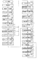
図11は、主基板31に搭載される遊技制御用マイクロコンピュータ560(具体的には、CPU56)が実行する特別図柄プロセス処理(ステップS26)のプログラムの一例を示すフローチャートである。上述したように、特別図柄プロセス処理では特別図柄表示器8または特別図柄表示器8および大入賞口を制御するための処理が実行される。特別図柄プロセス処理において、CPU56は、始動入賞口14に遊技球が入賞したことを検出するための始動口スイッチ14aがオンしていたら、すなわち、始動入賞口14への始動入賞が発生していたら、始動口スイッチ通過処理を実行する(ステップS311,S312)。そして、ステップS300〜S310のうちのいずれかの処理を行う。始動口スイッチ14aがオンしていなければ、内部状態に応じて、ステップS300〜S310のうちのいずれかの処理を行う。
FIG. 11 is a flowchart showing an example of a special symbol process (step S26) program executed by the game control microcomputer 560 (specifically, the CPU 56) mounted on the
ステップS300〜S310の処理は、以下のような処理である。 The processes in steps S300 to S310 are as follows.
特別図柄通常処理(ステップS300):特別図柄プロセスフラグの値が0であるときに実行される。遊技制御用マイクロコンピュータ560は、特別図柄の可変表示が開始できる状態になると、保留記憶数バッファに記憶される数値データの記憶数(保留記憶数)を確認する。保留記憶数バッファに記憶される数値データの記憶数は保留記憶数カウンタのカウント値により確認できる。また、保留記憶数カウンタのカウント値が0でなければ、遊技制御用マイクロコンピュータ560は、大当り判定処理を実行し、特別図柄の可変表示の表示結果を大当りとするか否かを決定する。また、大当りとする場合には大当りフラグをセットする。そして、内部状態(特別図柄プロセスフラグ)をステップS301に応じた値(この例では1)に更新する。なお、大当りフラグは、大当り遊技が終了するときにリセットされる。
Special symbol normal processing (step S300): Executed when the value of the special symbol process flag is zero. When the
変動パターン設定処理(ステップS301):特別図柄プロセスフラグの値が1であるときに実行される。また、変動パターンを決定し、その変動パターンにおける変動時間(可変表示時間:可変表示を開始してから表示結果を導出表示(停止表示)するまでの時間)を特別図柄の可変表示の変動時間とすることに決定する。また、特別図柄の変動時間を計測する変動時間タイマをスタートさせる。そして、内部状態(特別図柄プロセスフラグ)をステップS302に対応した値(この例では2)に更新する。 Fluctuation pattern setting process (step S301): This process is executed when the value of the special symbol process flag is 1. Also, the variation pattern is determined, and the variation time in the variation pattern (variable display time: the time from the start of variable display until the display result is derived and displayed (stop display)) is defined as the variation display variation time of the special symbol. Decide to do. Also, a variable time timer for measuring the special symbol variable time is started. Then, the internal state (special symbol process flag) is updated to a value (2 in this example) corresponding to step S302.
表示結果指定コマンド送信処理(ステップS302):特別図柄プロセスフラグの値が2であるときに実行される。演出制御用マイクロコンピュータ100に、表示結果指定コマンドを送信する制御を行う。そして、内部状態(特別図柄プロセスフラグ)をステップS303に対応した値(この例では3)に更新する。
Display result designation command transmission process (step S302): This process is executed when the value of the special symbol process flag is 2. Control for transmitting a display result designation command to the
特別図柄変動中処理(ステップS303):特別図柄プロセスフラグの値が3であるときに実行される。変動パターン設定処理で選択された変動パターンの変動時間が経過(ステップS301でセットされる変動時間タイマがタイムアウトすなわち変動時間タイマの値が0になる)すると、演出制御用マイクロコンピュータ100に、図柄確定指定コマンドを送信する制御を行い、内部状態(特別図柄プロセスフラグ)をステップS304に対応した値(この例では4)に更新する。なお、演出制御用マイクロコンピュータ100は、遊技制御用マイクロコンピュータ560が送信する図柄確定指定コマンドを受信すると演出表示装置9において第4図柄が停止されるように制御する。
Special symbol changing process (step S303): This process is executed when the value of the special symbol process flag is 3. When the variation time of the variation pattern selected in the variation pattern setting process elapses (the variation time timer set in step S301 times out, that is, the variation time timer value becomes 0), the
特別図柄停止処理(ステップS304):特別図柄プロセスフラグの値が4であるときに実行される。大当りフラグがセットされている場合に、内部状態(特別図柄プロセスフラグ)をステップS305に対応した値(この例では5)に更新する。また、小当りフラグがセットされている場合には、内部状態(特別図柄プロセスフラグ)をステップS308に対応した値(この例では8)に更新する。大当りフラグおよび小当りフラグのいずれもセットされていない場合には、内部状態(特別図柄プロセスフラグ)をステップS300に対応した値(この例では0)に更新する。なお、この実施の形態では、特別図柄プロセスフラグの値が4となったことにもとづいて、ステップS36の特別図柄表示制御処理において特別図柄の停止図柄を停止表示するための特別図柄表示制御データが特別図柄表示制御データ設定用の出力バッファに設定され、ステップS22の表示制御処理において出力バッファの設定内容に応じて実際に特別図柄の停止図柄が停止表示される。 Special symbol stop process (step S304): executed when the value of the special symbol process flag is 4. When the big hit flag is set, the internal state (special symbol process flag) is updated to a value (5 in this example) corresponding to step S305. If the small hit flag is set, the internal state (special symbol process flag) is updated to a value (8 in this example) corresponding to step S308. If neither the big hit flag nor the small hit flag is set, the internal state (special symbol process flag) is updated to a value corresponding to step S300 (in this example, 0). In this embodiment, based on the value of the special symbol process flag being 4, special symbol display control data for stopping and displaying the special symbol stop symbol in the special symbol display control process of step S36 is provided. The special symbol display control data is set in the output buffer, and the special symbol stop symbol is actually stopped and displayed according to the setting contents of the output buffer in the display control processing in step S22.
大入賞口開放前処理(ステップS305):特別図柄プロセスフラグの値が5であるときに実行される。大入賞口開放前処理では、大入賞口を開放する制御を行う。具体的には、カウンタ(例えば、大入賞口に入った遊技球数をカウントするカウンタ)などを初期化するとともに、ソレノイド21を駆動して大入賞口を開放状態にする。また、タイマによって大入賞口開放中処理の実行時間を設定し、内部状態(特別図柄プロセスフラグ)をステップS306に対応した値(この例では6)に更新する。なお、大入賞口開放前処理は各ラウンド毎に実行されるが、第1ラウンドを開始する場合には、大入賞口開放前処理は大当り遊技を開始する処理でもある。
Preliminary winning opening opening process (step S305): This is executed when the value of the special symbol process flag is 5. In the pre-opening process for the big prize opening, control for opening the big prize opening is performed. Specifically, a counter (for example, a counter that counts the number of game balls that have entered the big prize opening) is initialized and the
大入賞口開放中処理(ステップS306):特別図柄プロセスフラグの値が6であるときに実行される。大当り遊技状態中のラウンド表示の演出制御コマンドを演出制御用マイクロコンピュータ100に送信する制御や大入賞口の閉成条件の成立を確認する処理等を行う。なお、「大入賞口の閉成条件」は、大入賞口内の上流側のカウントスイッチ23により検出された大入賞口への遊技球の入賞数が所定数(本例では、10個)に達したことにもとづいて成立する。大入賞口の閉成条件が成立し、かつ、まだ残りラウンドがある場合には、内部状態(特別図柄プロセスフラグ)をステップS305に対応した値(この例では5)に更新する。また、全てのラウンドを終えた場合には、内部状態(特別図柄プロセスフラグ)をステップS307に対応した値(この例では7)に更新する。
Large winning opening opening process (step S306): This process is executed when the value of the special symbol process flag is 6. A control for transmitting a presentation control command for round display during the big hit gaming state to the
大当り終了処理(ステップS307):特別図柄プロセスフラグの値が7であるときに実行される。大当り遊技状態が終了したことを遊技者に報知する表示制御を演出制御用マイクロコンピュータ100に行わせるための制御を行う。また、遊技状態を示すフラグ(例えば、確変フラグや時短フラグ)をセットする処理を行う。そして、内部状態(特別図柄プロセスフラグ)をステップS300に対応した値(この例では0)に更新する。
Big hit end process (step S307): executed when the value of the special symbol process flag is 7. Control is performed to cause the
小当り開放前処理(ステップS308):特別図柄プロセスフラグの値が8であるときに実行される。小当り開放前処理では、大入賞口を開放する制御を行う。具体的には、カウンタ(例えば、大入賞口に入った遊技球数をカウントするカウンタ)などを初期化するとともに、ソレノイド21を駆動して大入賞口を開放状態にする。また、タイマによって大入賞口開放中処理の実行時間を設定し、内部状態(特別図柄プロセスフラグ)をステップS309に対応した値(この例では9)に更新する。なお、小当り開放前処理は小当り遊技中の大入賞口の開放毎に実行されるが、小当り遊技中の最初の開放を開始する場合には、小当り開放前処理は小当り遊技を開始する処理でもある。
Small hit release pre-processing (step S308): This process is executed when the value of the special symbol process flag is 8. In the pre-opening process for small hits, control is performed to open the big prize opening. Specifically, a counter (for example, a counter that counts the number of game balls that have entered the big prize opening) is initialized and the
小当り開放中処理(ステップS309):特別図柄プロセスフラグの値が9であるときに実行される。大入賞口の閉成条件の成立を確認する処理等を行う。なお、「大入賞口の閉成条件」は、大入賞口内の上流側のカウントスイッチ23により検出された大入賞口への遊技球の入賞数が所定数(本例では、10個)に達したことにもとづいて成立する。大入賞口の閉成条件が成立し、かつ、まだ大入賞口の開放回数が残っている場合には、内部状態(特別図柄プロセスフラグ)をステップS308に対応した値(この例では8)に更新する。また、全てのラウンドを終えた場合には、内部状態(特別図柄プロセスフラグ)をステップS310に対応した値(この例では10(10進数))に更新する。
Small hit release processing (step S309): executed when the value of the special symbol process flag is 9. Processing to confirm the establishment of the closing condition of the big prize opening is performed. Note that the “close condition of the big prize opening” is that the number of winning game balls to the big prize opening detected by the
小当り終了処理(ステップS310):特別図柄プロセスフラグの値が10であるときに実行される。小当り遊技状態が終了したことを遊技者に報知する表示制御を演出制御用マイクロコンピュータ100に行わせるための制御を行う。そして、内部状態(特別図柄プロセスフラグ)をステップS300に対応した値(この例では0)に更新する。
Small hit end process (step S310): executed when the value of the special symbol process flag is 10. Control is performed to cause the
次に、遊技制御用マイクロコンピュータ560(具体的には、CPU56)が実行する普通図柄プロセス処理(ステップS29)について説明する。図12は、普通図柄プロセス処理の一例を示すフローチャートである。普通図柄プロセス処理では、CPU56は、ゲート32を遊技球が通過してゲートスイッチ32aがオン状態となったことを検出すると(ステップS111)、ゲートスイッチ通過処理(ステップS112)を実行する。そして、CPU56は、普通図柄プロセスフラグの値に応じてステップS100〜S103に示された処理のうちのいずれかの処理を実行する。
Next, the normal symbol process (step S29) executed by the game control microcomputer 560 (specifically, the CPU 56) will be described. FIG. 12 is a flowchart showing an example of the normal symbol process. In the normal symbol process, when detecting that the game ball has passed through the
ゲートスイッチ通過処理(ステップS112):CPU56は、ゲート通過記憶カウンタのカウント値(ゲート通過記憶数)が最大値(この例では「4」)に達しているか否か確認する。最大値に達していなければ、ゲート通過記憶カウンタのカウント値を+1する。なお、ゲート通過記憶カウンタの値に応じて普通図柄保留記憶表示器41のLEDが点灯される。そして、CPU56は、普通図柄当り判定用乱数(ランダム4)の値を抽出し、ゲート通過記憶数の値に対応した保存領域(普通図柄判定用バッファ)に格納する処理を行う。
Gate switch passage processing (step S112): The CPU 56 checks whether or not the count value (gate passage storage number) of the gate passage storage counter has reached the maximum value ("4" in this example). If the maximum value has not been reached, the count value of the gate passage storage counter is incremented by one. Note that the LED of the normal symbol
普通図柄通常処理(ステップS100):CPU56は、普通図柄の変動を開始することができる状態(例えば普通図柄プロセスフラグの値がステップS100を示す値となっている場合、具体的には、普通図柄表示器10において普通図柄の変動表示がなされておらず、かつ、普通図柄表示器10に当り図柄が導出表示されたことにもとづく可変入賞球装置15の開閉動作中でもない場合)には、ゲート通過記憶数の値を確認する。具体的には、ゲート通過記憶数カウンタのカウント値を確認する。ゲート通過記憶数が0でなければ、当りとするか否か(普通図柄の停止図柄を当り図柄とするか否か)を決定する。そして、普通図柄プロセスタイマに普通図柄の変動時間をセットし、タイマをスタートさせる。そして、普通図柄プロセスフラグの値を普通図柄変動処理(ステップS101)を示す値(具体的には「1」)に更新する。
Normal symbol normal processing (step S100): The CPU 56 is in a state where normal symbol variation can be started (for example, when the value of the normal symbol process flag is a value indicating step S100, specifically, the normal symbol process). When the
普通図柄変動処理(ステップS101):CPU56は、普通図柄プロセスタイマがタイムアウトしたか否か確認し、タイムアウトしていたら、普通図柄表示器10における普通図柄の変動を停止し、普通図柄プロセスタイマに普通図柄停止図柄表示時間をセットし、タイマをスタートさせる。そして、普通図柄プロセスフラグの値を普通図柄停止処理(ステップS102)を示す値(具体的には「2」)に更新する。 Normal symbol variation processing (step S101): The CPU 56 confirms whether or not the normal symbol process timer has timed out. Set the symbol stop symbol display time and start the timer. Then, the value of the normal symbol process flag is updated to a value (specifically “2”) indicating the normal symbol stop process (step S102).
普通図柄停止処理(ステップS102):CPU56は、普通図柄プロセスタイマがタイムアウトしたか否かを確認し、タイムアウトしていたら、普通図柄の停止図柄が当り図柄であるかどうかを確認する。当り図柄でなければ(はずれ図柄であれば)、普通図柄プロセスフラグの値を普通図柄通常処理(ステップS100)を示す値(具体的には「0」)に更新する。一方、普通図柄の停止図柄が当り図柄であれば、普通図柄プロセスタイマに普通電動役物作動時間をセットし、タイマをスタートさせる。また、現在の遊技状態が高ベース状態であるか否かを確認し、高ベース状態であれば、高ベース状態のときの普通電動役物(可変入賞球装置15)の開放パターンを選択し、低ベース状態であれば、低ベース状態のときの普通電動役物(可変入賞球装置15)の開放パターンを選択し、選択した開放パターンを設定する。そして、普通図柄プロセスフラグの値を普通電動役物作動処理(ステップS103)を示す値(具体的には「3」)に更新する。 Normal symbol stop process (step S102): The CPU 56 checks whether or not the normal symbol process timer has timed out. If it has timed out, the CPU 56 checks whether or not the normal symbol stop symbol is a winning symbol. If it is not a winning symbol (if it is a missing symbol), the value of the normal symbol process flag is updated to a value (specifically, “0”) indicating the normal symbol normal processing (step S100). On the other hand, if the stop symbol of the normal symbol is a winning symbol, the normal electric accessory operating time is set in the normal symbol process timer, and the timer is started. Further, it is confirmed whether or not the current gaming state is a high base state, and if it is a high base state, an opening pattern of the ordinary electric accessory (variable winning ball device 15) in the high base state is selected, If in the low base state, the release pattern of the ordinary electric accessory (variable winning ball apparatus 15) in the low base state is selected, and the selected release pattern is set. Then, the value of the normal symbol process flag is updated to a value (specifically “3”) indicating the normal electric accessory operation processing (step S103).
普通電動役物作動処理(ステップS103):CPU56は、普通図柄プロセスタイマがタイムアウトしていないことを条件に、普通電動役物(可変入賞球装置15)への遊技球の入賞個数(始動入賞口14への入賞個数)をカウントする普通電動役物入賞カウント処理を実行し、また、設定された開放パターンで普通電動役物の開放を行う(可変入賞球装置15の開閉動作を実行する)普通電動役物開放パターン処理を実行する。そして、普通図柄プロセスタイマがタイムアウトすると、普通図柄プロセスフラグの値を普通図柄通常処理(ステップS100)を示す値(具体的には「0」)に更新する。
Normal electric accessory actuating process (step S103): The CPU 56 is based on the condition that the normal symbol process timer has not timed out, and the number of game balls to be awarded to the normal electric accessory (variable winning ball apparatus 15) (start winning prize opening). 14 is performed, and the ordinary electric accessory is counted with the set opening pattern (the opening / closing operation of the variable winning
図13は、ステップS23の異常入賞判定処理を示すフローチャートである。異常入賞判定処理において、遊技制御用マイクロコンピュータ560(具体的には、CPU56)は、特別図柄プロセスフラグの値が5以上であるか否か確認する(ステップS250)。特別図柄プロセスフラグの値が5以上であるときは(ステップS250のY)、大当り遊技中または小当り遊技中である状態である。そのような状態であれば、大入賞口に遊技球が入賞する可能性があるので、大入賞口への異常入賞の確認処理を行わずに、ステップS255の処理に移行する。 FIG. 13 is a flowchart showing the abnormal winning determination process in step S23. In the abnormal winning determination process, the game control microcomputer 560 (specifically, the CPU 56) checks whether or not the value of the special symbol process flag is 5 or more (step S250). When the value of the special symbol process flag is 5 or more (Y in Step S250), the game is in the big hit game or the small hit game. If it is in such a state, there is a possibility that a game ball may win the big winning opening, so the process proceeds to the process of step S255 without performing the abnormal winning confirmation process to the big winning opening.
特別図柄プロセスフラグの値が5未満である状態は、大当り遊技も小当り遊技も行われていない状態である。このような状態のときに大入賞口に遊技球の入賞があれば、その入賞は異常入賞であると判断することができる。従って、以下に示す大入賞口への異常入賞の確認処理を行う。 The state where the value of the special symbol process flag is less than 5 is a state where neither a big hit game nor a small hit game is played. In this state, if there is a game ball winning at the big winning opening, it can be determined that the winning is an abnormal winning. Therefore, an abnormal winning confirmation process for the special winning opening shown below is performed.
すなわち、特別図柄プロセスフラグの値が5未満であれば(ステップS250のN)、CPU56は、スイッチオンバッファ0(入力ポート0に対応するスイッチオンバッファ)の内容をレジスタにロードする(ステップS251)。そして、CPU56は、ロードしたスイッチオンバッファ0の内容とカウントスイッチ入力ビット判定値(01(H)、図7参照)との論理積をとる(ステップS252)。スイッチオンバッファ0の内容が01(H)であったとき、すなわちカウントスイッチ23がオンしているときには、論理積の演算結果は01(H)になる。カウントスイッチ23がオンしていないときには、論理積の演算結果は、0(00(H))になる。
That is, if the value of the special symbol process flag is less than 5 (N in Step S250), the CPU 56 loads the contents of the switch-on buffer 0 (the switch-on buffer corresponding to the input port 0) into the register (Step S251). . Then, the CPU 56 calculates the logical product of the contents of the loaded switch-on
論理積の演算結果が0でない場合には(ステップS253のN)、すなわち、カウントスイッチ23がオンしていれば、CPU56は、大入賞口への異常入賞が生じたと判定し、エラーが発生したと判定された回数(判定結果にもとづいてセキュリティ信号が出力されると減算される)を示す信号出力数カウンタを1加算する(ステップS254)。この実施の形態では、ステップS254で信号出力数カウンタに1加算されたことにもとづいて、情報出力処理(S31参照)が実行されることによって、大入賞口への異常入賞が検出されたときに、セキュリティ信号が所定時間(本例では、0.2秒)外部出力される。
If the result of the logical product is not 0 (N in step S253), that is, if the
ステップS255では、CPU56は、普通図柄プロセスフラグの値が3であるか否か確認する(ステップS255)。普通図柄プロセスフラグの値が3である状態は、普通電動役物(可変入賞球装置15)が開状態であると判断される状態(可変入賞球装置15が物理的に開いている状態のときと、可変入賞球装置15が物理的に閉鎖されてから所定のインターバル期間を経過するまでの状態のときとを含む)である。そのような状態であれば(ステップS255のY)、始動入賞口14に遊技球が入賞する可能性があるので、始動入賞口14への異常入賞の確認処理を行わずに、ステップS259aに移行する。
In step S255, the CPU 56 checks whether or not the value of the normal symbol process flag is 3 (step S255). The state where the value of the normal symbol process flag is 3 is a state where it is determined that the ordinary electric accessory (variable winning ball device 15) is in the open state (when the variable winning
普通図柄プロセスフラグの値が3でない状態は(ステップS255のN)、普通電動役物(可変入賞球装置15)が開状態以外の状態と判断される状態である。このような状態のときに始動入賞口14に遊技球の入賞があれば、その入賞は異常入賞である可能性がある。従って、以下に示す始動入賞口14への異常入賞の確認処理を行う。
The state where the value of the normal symbol process flag is not 3 (N in Step S255) is a state in which the normal electric accessory (variable winning ball device 15) is determined to be in a state other than the open state. If there is a game ball winning in the
すなわち、普通図柄プロセスフラグの値が3でなければ(ステップS255のN)、CPU56は、スイッチオンバッファ2(入力ポート2に対応するスイッチオンバッファ)の内容をレジスタにロードする(ステップS256)。そして、CPU56は、ロードしたスイッチオンバッファ2の内容と始動口スイッチ入力ビット判定値(01(H)、図7参照)との論理積をとる(ステップS257)。スイッチオンバッファ2の内容が01(H)であったとき、すなわち始動口スイッチ14aがオンしているときには、論理積の演算結果は01(H)になる。始動口スイッチ14aがオンしていないときには、論理積の演算結果は、0(00(H))になる。
That is, if the value of the normal symbol process flag is not 3 (N in step S255), the CPU 56 loads the contents of the switch-on buffer 2 (the switch-on buffer corresponding to the input port 2) into the register (step S256). Then, the CPU 56 calculates the logical product of the content of the loaded switch-on
論理積の演算結果が0でない場合には(ステップS258のN)、すなわち、始動口スイッチ14aがオンしていれば、CPU56は、始動入賞口14への異常入賞が生じたと判定し、信号出力数カウンタを1加算し(ステップS259)、ステップS259aに移行する。この実施の形態では、ステップS259で信号出力数カウンタに1加算されたことにもとづいて、情報出力処理(S31参照)が実行されることによって、始動入賞口14への異常入賞が検出されたときに、セキュリティ信号が所定時間(本例では、0.2秒)外部出力される。
If the operation result of the logical product is not 0 (N in step S258), that is, if the start port switch 14a is turned on, the CPU 56 determines that an abnormal winning has occurred in the
以上のような処理によって、大当り遊技も小当り遊技も行われていない状態においてカウントスイッチ23がオンした場合には、大入賞口への異常入賞が発生したと判定され、情報出力処理(ステップS31参照)においてセキュリティ信号が外部出力されることになる。また、可変入賞球装置15が開閉動作していない状態(始動入賞口14が開状態以外の状態)において始動口スイッチ14aがオンした場合にも、始動入賞口14への異常入賞が発生したと判定され、情報出力処理(ステップS31参照)においてセキュリティ信号が外部出力されることになる。
When the
なお、ステップS250の処理では、CPU56が、特別図柄プロセスフラグの値にもとづいて大入賞口への異常入賞が生じたか否か判定するようにしている。そのため、1つのデータにもとづいて異常入賞が生じたか否か判定できるので、判定処理を簡素化することができる。また、上述したように、特別可変入賞球装置20が閉鎖した後に大当り終了処理または小当り終了処理が所定時間実行されるので、特別可変入賞球装置20が閉鎖する直前に大入賞口に入賞した遊技球が、特別図柄プロセスフラグの値が0に戻った後にカウントスイッチ23で検出されてしまうということが防止され、正規の入賞であるにもかかわらずセキュリティ信号が外部出力されたりエラーが報知されてしまうようなことはない。
In the process of step S250, the CPU 56 determines whether or not an abnormal winning to the big winning opening has occurred based on the value of the special symbol process flag. Therefore, since it can be determined whether or not an abnormal winning has occurred based on one data, the determination process can be simplified. Further, as described above, since the big hit end process or the small hit end process is executed for a predetermined time after the special variable winning
また、ステップS255の処理では、CPU56が、普通図柄プロセスフラグの値にもとづいて始動入賞口14への異常入賞が生じたか否か判定するようにしている。そのため、1つのデータにもとづいて異常入賞が生じたか否か判定できるので、判定処理を簡素化することができる。また、上述したように、異常入賞を判定するタイミングを可変入賞球装置15を閉鎖するタイミングよりも遅らせる方法として、普通図柄プロセスフラグの値が3から0に切り替わる所定時間前に可変入賞球装置15を閉鎖し、普通図柄プロセスフラグの値が3から0に切り替わった時点で異常入賞の判定を行うようにしているので、可変入賞球装置15が閉鎖する直前に始動入賞口14に入賞した遊技球が、普通図柄プロセスフラグの値が0に戻った後に始動口スイッチ14aで検出されてしまうということが防止され、正規の入賞であるにもかかわらずセキュリティ信号が外部出力されたりエラーが報知されてしまうようなことはない。
In the process of step S255, the CPU 56 determines whether or not an abnormal winning to the start winning
なお、可変入賞球装置15を閉鎖すると同時に普通図柄プロセスフラグの値が3から0に切り替え、普通図柄プロセスフラグの値が3から0に切り替わってから所定時間経過後に異常入賞の判定を行うようにしてもよい。また、大入賞口への異常入賞の判定においても、同様の方法により異常入賞を判定するタイミングを大入賞口(特別可変入賞球装置20)を閉鎖するタイミングよりも遅らせるようにしてもよい。
At the same time that the variable winning
ステップS259aでは、CPU56は、始動口スイッチ14aにおいて異常が発生しているか否かを判定する始動口スイッチ判定処理を行う。その後、CPU56は、入賞口スイッチ29a,30aにおいて異常が発生しているか否かを判定する入賞口スイッチ判定処理(ステップS259b)と、カウントスイッチ23において異常が発生しているか否かを判定するカウントスイッチ判定処理(ステップS259c)と、ゲートスイッチ32aにおいて異常が発生しているか否かを判定するゲートスイッチスイッチ判定処理(ステップS259d)とを行う。ステップS259a〜259dの処理が終了すると、異常入賞判定処理は終了する。なお、図13に示す例に限らず、ステップS259a〜259dの処理は、任意の順で実行されてもよい。また、図13に示す例に限らず、ステップS259a〜259dの処理のうちのいずれかまたは複数の処理のみを実行するようにしてもよい。
In step S259a, the CPU 56 performs a start port switch determination process for determining whether an abnormality has occurred in the start port switch 14a. Thereafter, the CPU 56 determines whether or not an abnormality has occurred in the prize opening switches 29a and 30a (step S259b), and counts to determine whether or not an abnormality has occurred in the
図14は、ステップS259aの始動口スイッチ判定処理を示すフローチャートである。なお、入賞口スイッチ判定処理(ステップS259b)、カウントスイッチ判定処理(ステップS259c)およびゲートスイッチ判定処理(ステップS259d)は、始動口スイッチ判定処理における始動口スイッチを確認する処理を、判定対象のスイッチを確認する処理に置き換えることで実現されるため説明を省略する。また、この実施の形態では、後述する情報出力処理においてセキュリティ信号を出力している期間中に、新たに別のエラーが発生したと判定された場合(例えば、他のスイッチの判定処理において判定された場合)にも、新たに発生したエラーにもとづいてセキュリティ信号を出力することを可能にするため、エラーが発生したと判定された回数を示す信号出力数カウンタは共通して用いられる。信号出力数カウンタは、エラーが発生したと判定されると1加算され、判定結果にもとづいてセキュリティ信号が出力されると1減算される。ただし、後述する始動口監視タイマ、連続検出タイマおよび再検出回数カウンタは、スイッチごとに設けられている。 FIG. 14 is a flowchart showing the start port switch determination process in step S259a. In the winning opening switch determination process (step S259b), the count switch determination process (step S259c), and the gate switch determination process (step S259d), the process for confirming the start port switch in the start port switch determination process is the switch to be determined. Since it is realized by replacing with a process for confirming, the description is omitted. Also, in this embodiment, when it is determined that another error has newly occurred during the period in which the security signal is output in the information output process described later (for example, it is determined in the determination process of another switch). In addition, in order to be able to output a security signal based on a newly generated error, a signal output number counter indicating the number of times it is determined that an error has occurred is commonly used. The signal output number counter is incremented by 1 when it is determined that an error has occurred, and is decremented by 1 when a security signal is output based on the determination result. However, a start port monitoring timer, a continuous detection timer, and a redetection number counter, which will be described later, are provided for each switch.
始動口スイッチ判定処理において、CPU56は、始動口スイッチ14aがオンであるか否かを判定する(ステップS2501)。なお、この処理において、CPU56は、スイッチオンバッファ2(入力ポート2に対応するスイッチオンバッファ)の内容をレジスタにロードし、ロードしたスイッチオンバッファ2の内容と始動口スイッチ入力ビット判定値(01(H)、図7参照)との論理積をとり、論理積の演算結果が01(H)であったときに、始動口スイッチ14aがオンしていると判断する。また、論理積の演算結果が0(00(H))であったときに、始動口スイッチ14aがオンしていないと判断する。
In the start port switch determination process, the CPU 56 determines whether or not the start port switch 14a is on (step S2501). In this process, the CPU 56 loads the contents of the switch-on buffer 2 (the switch-on buffer corresponding to the input port 2) into the register, and the contents of the loaded switch-on
始動口スイッチ14aがオンでないと判断した場合には、CPU56は、始動口スイッチ14aがオンの状態が継続している期間が予め定められた特定期間(例えば2秒間)に達しているか否かを判断するための連続検出タイマをリセットする(ステップS2515)。連続検出タイマは、始動口スイッチ14aがオンの状態が特定期間(例えば2秒間)継続している(すなわち始動口において球詰まりが発生している)か否かを判定するために用いられる。連続検出タイマは、前回の始動口スイッチ判定処理においてオンの状態であると判定され、今回もオンの状態であると判定されたときに特定期間(例えば2秒)セットされ(後述するステップS2502,S2506)、オンの状態が継続しているときに減算される(後述するステップS2502,S2503)。また、連続検出タイマは、始動口スイッチ判定処理においてオンの状態であると判定されたとき(ステップS2501,S2515)やタイムアウトしたとき(ステップS2504〜S2504a)にリセットされる。 When determining that the start port switch 14a is not on, the CPU 56 determines whether or not the period during which the start port switch 14a is on has reached a predetermined specific period (for example, 2 seconds). The continuous detection timer for determination is reset (step S2515). The continuous detection timer is used to determine whether or not the start port switch 14a is on for a specific period (for example, 2 seconds) (that is, a ball clogging has occurred at the start port). The continuous detection timer is determined to be in an on state in the previous start port switch determination process, and is set for a specific period (for example, 2 seconds) when it is determined to be in an on state this time (step S2502, which will be described later). S2506), subtraction is performed when the ON state continues (steps S2502 and S2503 described later). The continuous detection timer is reset when it is determined that the start-up switch determination process is in an ON state (steps S2501 and S2515) or when a time-out occurs (steps S2504 to S2504a).
また、CPU56は、始動口スイッチ14aがオンとなった時点から予め定められた監視時間が経過するまでに再度オンとなるか否かを判断するための始動口監視タイマを1減算する(ステップS2516)。始動口監視タイマは、所定期間に始動口スイッチ14aがオンとなる回数が所定回数に達するか否か(後述する不正行為による異常入賞が発生しているか否か)を判定するために用いられる。すなわち、始動口スイッチ14aが継続してオンとなっている状態ではないが、所定期間内の検出回数が所定回数を超えている状態(つまり、通常遊技球が始動口を通過可能な間隔よりも短い間隔で通過している状態)であるか否かを判定するために用いられる。始動口監視タイマは、始動口スイッチ判定処理においてオンの状態であると判定されると、始動口スイッチ14aに対して定められた監視時間にセットされ(後述するステップS2510)、オフの状態であると判定されると減算される。なお、始動口監視タイマがセットされていない場合(すなわち、一度も入賞していない(始動口スイッチ14aがオンになっていない)場合)には、ステップS2516の処理を省略する。
Further, the CPU 56
この実施の形態では、スイッチの種別に応じて異なる監視時間が定められている。図15は、スイッチ種別ごとに定められた監視時間を示す説明図である。図15に示すように、ゲートスイッチ32aに対して監視時間が0.03秒と定められ、始動口スイッチ14aに対して監視時間が0.05秒と定められ、入賞口スイッチ29a,30aに対して監視時間が0.04秒と定められ、カウントスイッチ23に対して監視時間が0.06秒と定められている。この実施の形態では、監視時間内の検出回数が所定回数を超えている状態(つまり、通常遊技球が入賞口を通過可能な間隔よりも短い間隔で通過していることになる状態)を不正行為による異常入賞が発生していると判定する。図15に示すように、スイッチ種別に応じて異なる監視時間を設定することによって、入賞口の形状等の違いによって通常遊技球が通過可能な間隔が異なることに対応することができる。すなわち、入賞口の形状等に応じて異なる監視時間を設定することによって、不正行為がなされていないにも関わらず誤って異常入賞と判定することを防止することができる。
In this embodiment, different monitoring times are determined according to the type of switch. FIG. 15 is an explanatory diagram showing the monitoring time determined for each switch type. As shown in FIG. 15, the monitoring time is set to 0.03 seconds for the
始動口スイッチ14aがオンであると判断した場合には、CPU56は、始動口監視タイマの値が始動口スイッチに対して定められた監視時間(図15の例では0.05秒)であるか否かを判断する(ステップS2502)。すなわち、前回始動口スイッチ14aがオンであると判断されたときに後述するステップS2510において設定された始動口監視タイマが、その後始動口スイッチ14aがオンでないと判断され(ステップS2501のN)、ステップS2516において減算されていないか否かを判断する。つまり、ステップS2502では、前回始動口スイッチ14aがオンであると判断された後に、1度もオフであると判断されることなく、再度オンであると判断されているかを確認することで、始動口スイッチ14aがオンの状態が継続しているか否かを確認する。なお、図14に示す例に限らず、例えば、始動口スイッチがオンであると判断した時に特定フラグをセットし、始動口スイッチがオフであると判断した時にその特定フラグをリセットするようにすれば、特定フラグの状態を確認することによって始動口スイッチ14aがオンの状態が継続しているか否かを確認することができる。 When determining that the start port switch 14a is on, the CPU 56 determines whether the value of the start port monitoring timer is the monitoring time set for the start port switch (0.05 seconds in the example of FIG. 15). It is determined whether or not (step S2502). That is, a start port monitoring timer set in step S2510 described later when it is determined that the start port switch 14a has been previously turned on is determined that the start port switch 14a has not been turned on thereafter (N in step S2501). In S2516, it is determined whether or not subtraction is performed. In other words, in step S2502, it is determined whether it has been determined to be on again without being determined to be off once after it has been determined that the start port switch 14a was on previously. It is confirmed whether or not the mouth switch 14a is kept on. In addition to the example shown in FIG. 14, for example, a specific flag is set when it is determined that the start port switch is on, and the specific flag is reset when it is determined that the start port switch is off. For example, by checking the state of the specific flag, it can be confirmed whether or not the start port switch 14a is kept on.
ステップS2502において、始動口監視タイマの値が始動口スイッチに対して定められた監視時間であると判断した場合(すなわち、始動口スイッチ14aがオンの状態が継続している場合)には、CPU56は、連続検出タイマを1減算し(ステップS2503)、連続検出タイマがタイムアウトしているか否かを判断する(ステップS2504)。すなわち、始動口スイッチ14aがオンの状態が継続している期間が予め定められた特定期間(例えば2秒)に達しているか否かを判断する。そして、連続検出タイマがタイムアウトしていると判断すると(ステップS2504のY)、CPU56は、連続検出タイマをリセットし(ステップS2504a)、球詰まりが発生していると判定して、信号出力数カウンタを1加算する(ステップS2505)。一方、ステップS2502において、始動口監視タイマの値が始動口スイッチに対して定められた監視時間ではないと判断した場合(すなわち、始動口スイッチ14aがオンの状態が継続しておらず、一度オフになった後にオンになった場合)には、CPU56は、あらためて連続検出タイマをセット(例えば、2秒間)し、ステップS2507に移行する。このように、この実施の形態では、ステップS2502〜S2505の処理を実行することによって、始動口スイッチ14aがオンの状態が特定期間(例えば2秒)継続した場合に、異常入賞(球詰まり)が発生したと判定し、信号出力数カウンタを1加算することで、情報出力処理においてセキュリティ信号を出力することができる。したがって、管理者はセキュリティ信号にもとづいて入賞領域における球詰まりの発生を検知することができる。
If it is determined in step S2502 that the value of the start port monitoring timer is the monitoring time set for the start port switch (that is, if the start port switch 14a is kept on), the CPU 56
ステップS2507では、CPU56は、始動口監視タイマがタイムアウトしているか否かを判定する(ステップS2508)。そして、タイムアウトしている場合には、CPU56は、始動口スイッチ14aがオンとなった時点から監視時間(図15に示す0.04秒)が経過するまでに再度オンとなった回数を計数するための再検出回数カウンタを1加算し(ステップS2508)、タイムアウトしていない場合には再検出回数カウンタをリセットする(ステップS2509)。その後、CPU56は、始動口監視タイマに始動口スイッチ14aに対して定められた監視時間(図15に示す0.04秒)をセットする(ステップS2510)。なお、ステップS2508において、始動口監視タイマがセットされていない場合(すなわち、最初の入賞時)には、ステップS2509に移行するように制御する。また、この実施の形態では、始動口監視タイマがタイムアウトしていれば再検出回数カウンタをリセットするが、リセットしないようにして再検出回数カウンタで監視時間内に検出された通算回数(初めの入賞を回数として含む再検出回数)をカウントするようにしてもよい。 In step S2507, the CPU 56 determines whether or not the start port monitoring timer has timed out (step S2508). And when it has timed out, CPU56 counts the frequency | count of having turned on again after monitoring time (0.04 second shown in FIG. 15) passes since the start port switch 14a was turned on. The redetection counter is incremented by 1 (step S2508), and if the timeout has not occurred, the redetection counter is reset (step S2509). Thereafter, the CPU 56 sets the monitoring time (0.04 seconds shown in FIG. 15) determined for the start port switch 14a in the start port monitoring timer (step S2510). In step S2508, when the start port monitoring timer is not set (that is, at the time of the first winning prize), control is performed so as to proceed to step S2509. In this embodiment, if the start port monitoring timer has timed out, the re-detection number counter is reset. May be counted.
次いで、CPU56は、再検出回数カウンタの値が所定値(例えば、50回)以上であるか否かを判定し(ステップS2511)、所定値以上であれば、始動口スイッチ14aにおいて異常入賞が発生していると判定し、信号出力数カウンタを1加算する(ステップS2512)。ステップS2511では、始動口スイッチ14aがオンとなった時点から監視時間が経過するまでに再度オンとなった回数が所定回数に達しているか否かを確認される。すなわち、始動口スイッチ14aが継続してオンとなっている状態ではないが、所定期間の検出回数が所定回数を超えているため(つまり、通常遊技球が始動口を通過可能な間隔よりも短い間隔で通過していることになるため)、始動口に入賞する遊技球を不正に操作する(例えば、同じ遊技球が何度も繰り返し始動口を通過するように操作する)不正行為や、外部から電波を照射してスイッチを誤作動させることで、遊技球を検出した場合に出力する信号を出力させる不正行為などが行われることによる異常入賞が発生していると判定する。このように、この実施の形態では、ステップS2511〜S2514の処理を実行することによって、始動口スイッチ14aがオンとなった時点から監視時間が経過するまでに再度オンとなった回数が所定回数に達している場合に、始動口に入賞する遊技球を不正に操作する不正行為や、外部から電波を照射する不正行為などによる異常入賞が発生したと判定し、信号出力数カウンタを1加算することで、情報出力処理においてセキュリティ信号を出力することができる。したがって、管理者はセキュリティ信号にもとづいて入賞領域における異常入賞の発生を検知することができる。 Next, the CPU 56 determines whether or not the value of the re-detection number counter is equal to or greater than a predetermined value (for example, 50 times) (step S2511), and if it is equal to or greater than the predetermined value, an abnormal winning occurs at the start port switch 14a. The signal output number counter is incremented by 1 (step S2512). In step S2511, it is confirmed whether or not the number of times the start port switch 14a is turned on again from when the start port switch 14a is turned on has reached a predetermined number of times. That is, although the start port switch 14a is not continuously turned on, the number of detections in the predetermined period exceeds the predetermined number (that is, shorter than the interval at which the normal game ball can pass through the start port). Fraudulent acts such as illegally operating a game ball that wins the starting opening (for example, operating the same gaming ball repeatedly through the starting opening) It is determined that an abnormal prize has occurred due to an illegal act of outputting a signal to be output when a game ball is detected by irradiating a radio wave from the switch and causing the switch to malfunction. Thus, in this embodiment, by executing the processing of steps S2511 to S2514, the number of times the monitor is turned on again from when the start port switch 14a is turned on until the monitoring time elapses becomes a predetermined number. If it has been reached, it is determined that an abnormal prize has occurred due to an illegal act of illegally operating a game ball to be won at the start opening or an illegal act of radiating radio waves from the outside, and the signal output number counter is incremented by 1. Thus, the security signal can be output in the information output process. Therefore, the manager can detect the occurrence of abnormal winning in the winning area based on the security signal.
その後、CPU56は、再検出回数カウンタをリセットし(ステップS2513)、演出制御用マイクロコンピュータ100に、エラー報知を実行させるためのエラー報知指定コマンドを送信する制御を行い(ステップS2514)、始動口スイッチ判定処理を終了する。 Thereafter, the CPU 56 resets the re-detection number counter (step S2513), performs control to transmit an error notification designation command for executing the error notification to the effect control microcomputer 100 (step S2514), and starts the start switch. The determination process ends.
上述のように、入賞口スイッチ判定処理(ステップS259b)、カウントスイッチ判定処理(ステップS259c)およびゲートスイッチ判定処理(ステップS259d)は、始動口スイッチ判定処理における始動口スイッチを確認する処理を、判定対象のスイッチを確認する処理に置き換えることで実現される。具体的には、信号出力数カウンタは各スイッチの判定処理で共通して用いられるが、始動口監視タイマ、連続検出タイマおよび再検出回数カウンタはスイッチごとに設けられ、図14のフローと同様にそれぞれタイマ監視や再検出回数の計数、エラー情報指定コマンドの出力などの制御が行われる。なお、再検出回数が所定値に達しているときにエラーが発生したと判定しているが(ステップS2511)、各スイッチの判定処理で判定に用いられる所定値は、同じであってもよいし、スイッチごとに異なっていてもよいが、入賞口や盤面設計に応じた値が設定されることが望ましい。 As described above, the winning opening switch determination process (step S259b), the count switch determination process (step S259c), and the gate switch determination process (step S259d) determine the process for confirming the start port switch in the start port switch determination process. This is realized by replacing the target switch with a process for confirming the target switch. Specifically, the signal output number counter is commonly used in the determination processing of each switch, but the start port monitoring timer, the continuous detection timer, and the re-detection number counter are provided for each switch, as in the flow of FIG. Controls such as timer monitoring, re-detection count, and error information designation command output are performed. Although it is determined that an error has occurred when the number of re-detections has reached a predetermined value (step S2511), the predetermined value used for determination in the determination process of each switch may be the same. Although it may be different for each switch, it is desirable to set a value according to the winning opening and the board design.
図16は、ステップS24のセンサエラー判定処理を示すフローチャートである。センサエラー判定処理において、遊技制御用マイクロコンピュータ560(具体的には、CPU56)は、磁石センサ62からの磁石センサ信号を入力したか否かを確認する(ステップS260)。具体的には、CPU56は、スイッチオンバッファ1(入力ポート1に対応するスイッチオンバッファ)の内容をレジスタにロードし、ロードしたスイッチオンバッファ1の内容と磁石センサ信号入力ビット判定値(20(H)、図7参照)との論理積をとり、論理積の演算結果が20(H)であれば磁石センサ信号を入力したと判定する。
FIG. 16 is a flowchart showing the sensor error determination process in step S24. In the sensor error determination process, the game control microcomputer 560 (specifically, the CPU 56) checks whether or not the magnet sensor signal from the
磁石センサ信号を入力していれば(すなわち、磁石センサ62によって磁気が検出されていれば)、CPU56は、磁気異常が発生したと判定し、磁気異常を検出したことを示す磁気異常フラグをセットする(ステップS261)。この実施の形態では、ステップS261で磁気異常フラグがセットされたことにもとづいて、情報出力処理(S31参照)が実行されることによって、磁気異常が検出されたときに、セキュリティ信号が遊技機への電源が再投入され初期化処理が実行されるまで外部出力される。 If a magnet sensor signal is input (that is, if magnetism is detected by the magnet sensor 62), the CPU 56 determines that a magnetic abnormality has occurred, and sets a magnetic abnormality flag indicating that the magnetic abnormality has been detected. (Step S261). In this embodiment, when a magnetic abnormality is detected by executing an information output process (see S31) based on the magnetic abnormality flag being set in step S261, a security signal is sent to the gaming machine. Is output externally until the power is turned on again and initialization processing is executed.
また、CPU56は、エラー報知用LED31Aを点灯させて磁気異常が発生したことを報知する(ステップS262)とともに、エラー(磁気異常)が発生したことを報知することを指定するエラー報知指定コマンドを演出制御用マイクロコンピュータ100に対して送信する制御を行う(ステップS263)。なお、この実施の形態では、エラーの種別によらずエラー報知指定コマンドを送信しているが、エラーの種別ごとに異なるコマンドを送信し、演出制御用マイクロコンピュータ100において異なる報知を行わせるようにしてもよい。例えば磁気異常が発生したことを報知することを指定する場合には、磁気エラー報知指定コマンドを演出制御用マイクロコンピュータ100に送信するようにしてもよい。
Further, the CPU 56 turns on the
次いで、CPU56は、電波センサ61からの電波センサ信号を入力したか否かを確認する(ステップS264)。具体的には、CPU56は、スイッチオンバッファ1(入力ポート1に対応するスイッチオンバッファ)の内容をレジスタにロードし、ロードしたスイッチオンバッファ1の内容と電波センサ信号入力ビット判定値(10(H)、図7参照)との論理積をとり、論理積の演算結果が10(H)であれば電波センサ信号を入力したと判定する。
Next, the CPU 56 confirms whether or not the radio wave sensor signal from the radio wave sensor 61 is input (step S264). Specifically, the CPU 56 loads the contents of the switch-on buffer 1 (switch-on buffer corresponding to the input port 1) into a register, and loads the contents of the loaded switch-on
電波センサ信号を入力していれば(すなわち、電波センサ61によって電波が検出されていれば)、CPU56は、電波異常が発生したと判定し、信号出力数カウンタを1加算する(ステップS265)。この実施の形態では、ステップS265で信号出力数カウンタに1加算されたことにもとづいて、情報出力処理(S31参照)が実行されることによって、電波異常が検出されたときに、セキュリティ信号が所定時間(本例では、0.2秒)外部出力される。 If a radio wave sensor signal is input (that is, if a radio wave is detected by the radio wave sensor 61), the CPU 56 determines that radio wave abnormality has occurred, and adds 1 to the signal output number counter (step S265). In this embodiment, when a radio wave abnormality is detected by executing an information output process (see S31) based on the addition of 1 to the signal output number counter in step S265, a security signal is predetermined. Time (in this example, 0.2 seconds) is output externally.
図17は、ターミナル基板160に出力される各種信号を示すブロック図である。図17に示すように、この実施の形態では、主基板31に搭載されている遊技制御用マイクロコンピュータ560からターミナル基板160に対して、図柄確定回数1信号、始動口信号、大当り1信号、大当り2信号、大当り3信号、時短信号、入賞信号、セキュリティ信号、および高確中信号が、遊技制御用マイクロコンピュータ560側の情報出力処理(ステップS31参照)によって出力される。また、この実施の形態では、払出制御基板37に搭載されている払出制御用マイクロコンピュータ370から、主基板31を経由して、ターミナル基板160に対して、賞球情報が、払出制御用マイクロコンピュータ370側の情報出力処理によって出力される。
FIG. 17 is a block diagram showing various signals output to the
図柄確定回数1信号は、特別図柄の変動回数を通知するための信号である。始動口信号は、始動入賞口14への入賞個数を通知するための信号である。大当り1信号は、大当り遊技中(特別可変入賞球装置の動作中)であることを通知するための信号である。大当り2信号は、大当り遊技中(特別可変入賞球装置の動作中)で、または特別図柄の変動時間短縮機能が作動中(時短状態中)であることを通知するための信号である。大当り3信号は、15ラウンドの大当り遊技中であることを通知するための信号である。時短信号は、特別図柄の変動時間短縮機能が作動中(時短状態中)であることを通知するための信号である。
The
また、入賞信号は、既に説明したように、所定数分(この実施の形態では、10個分)の賞球を払い出すための所定の払出条件が成立したこと(始動入賞口14、大入賞口、普通入賞口29,30への入賞が発生したこと。賞球の払出までは行われていない。具体的には、近接スイッチ(入賞口スイッチ29a,30a、カウントスイッチ23、始動口スイッチ14a)からの検出信号を入力したことを条件として、所定の払出条件が成立したと判定されたこと。)を示す信号である。
In addition, as described above, the winning signal indicates that a predetermined payout condition for paying out a predetermined number of prize balls (10 balls in this embodiment) has been established (starting
また、セキュリティ信号は、遊技機のセキュリティ状態を示す信号である。具体的には、磁石センサ62の検出結果にもとづいて磁気異常が発生したと判定された場合に、セキュリティ信号が電源が再投入されて初期化処理が実行されるまでホールコンピュータなどの外部装置に出力される。また、電波センサ61の検出結果にもとづいて電波異常が発生したと判定された場合に、セキュリティ信号が所定期間(例えば、0.2秒間)ホールコンピュータなどの外部装置に出力される。また、大入賞口や始動入賞口14への異常入賞が検出された場合や、各種スイッチにおいて異常が検出された場合にも、セキュリティ信号が所定期間(例えば、0.2秒間)ホールコンピュータなどの外部装置に出力される。また、遊技機への電源投入が行われて初期化処理が実行された場合にも、セキュリティ信号が所定期間(例えば、0.2秒間)ホールコンピュータなどの外部装置に出力される。
The security signal is a signal indicating the security state of the gaming machine. Specifically, when it is determined that a magnetic abnormality has occurred based on the detection result of the
高確中信号は、遊技状態が高確率状態(確変状態)に制御されていることを示す信号である。この実施の形態では、高確中信号は、停電復旧してから所定条件が成立するまで(具体的には、最初の大当りが発生するまで)、ターミナル基板160を介して外部出力される。
The high probability signal is a signal indicating that the gaming state is controlled to a high probability state (probability change state). In this embodiment, the high-accuracy signal is externally output through the
また、賞球情報は、既に説明したように、賞球払出を特定数(本例では10個)検出するごとに出力される信号である。なお、この実施の形態では、所定数分(この実施の形態では、10個分)の賞球を払い出すための所定の払出条件が成立したこと(始動入賞口14、大入賞口、普通入賞口29,30への入賞が発生したこと。具体的には、近接スイッチ(入賞口スイッチ29a,30a、カウントスイッチ23、始動口スイッチ14a)からの検出信号を入力したことを条件として、所定の払出条件が成立したと判定されたこと。)にもとづいて入賞信号が外部出力され、入賞信号にもとづいてホール側で賞球数の把握を行うことができる。そのため、賞球情報については、外部出力しないように構成してもよい。
Further, as described above, the prize ball information is a signal that is output every time a specific number (10 in this example) of prize ball payouts is detected. In this embodiment, a predetermined payout condition for paying out a predetermined number of prize balls (10 balls in this embodiment) is satisfied (start winning
図18は、ステップS31の情報出力処理を示すフローチャートである。なお、図18に示す例では、情報出力処理で実行される処理のうちセキュリティ信号を外部出力する処理の部分について示し、その他の処理については記載を省略しているが、実際には、情報出力処理では、図18に示す処理の他に図柄確定回数1信号や、始動口信号、大当り1信号、大当り2信号、大当り3信号、時短信号、入賞信号、高確中信号を外部出力する処理も実行される。
FIG. 18 is a flowchart showing the information output process of step S31. In the example shown in FIG. 18, the process of externally outputting the security signal is shown in the process executed in the information output process, and the description of the other processes is omitted. In the processing, in addition to the processing shown in FIG. 18, processing for externally outputting a
情報出力処理において、CPU56は、磁気異常フラグがセットされているか否かを確認する(ステップS1001)。磁気異常フラグがセットされていれば(すなわち、磁気異常の発生が検出されていれば)、CPU56は、セットされていればセキュリティ信号情報タイマの値をクリアし(ステップS1002)、情報バッファのセキュリティ信号出力ビット位置(図6に示す例では出力ポート1のビット7)をセットする(ステップS1003)。情報バッファのセキュリティ信号出力ビット位置がセットされると、その後のステップS1014で情報バッファを出力値にセットし、ステップS1015で出力値を出力ポート1に出力することによって、セキュリティ信号が出力ポート1から出力される(オン状態となる)。
In the information output process, the CPU 56 checks whether or not the magnetic abnormality flag is set (step S1001). If the magnetic abnormality flag is set (that is, if occurrence of a magnetic abnormality is detected), the CPU 56 clears the value of the security signal information timer if it is set (step S1002), and the information buffer security is set. The signal output bit position (
以上に示したステップS1001〜S1003の処理によって、磁気異常が検出されると、遊技機への電源が再投入されて初期化処理が実行されるまで、磁気異常にもとづくセキュリティ信号が出力される。 If a magnetic abnormality is detected by the processing in steps S1001 to S1003 described above, a security signal based on the magnetic abnormality is output until the game machine is powered on again and the initialization process is executed.
なお、既に説明したように、磁気異常フラグはバックアップRAMに記憶され遊技機への電力供給が停止しても保持されるので、遊技機への電力供給停止後に再び電力供給が開始されても停電復旧処理(ステップS91,S92参照)が実行された場合には、磁気異常フラグが保持されていることにもとづいてステップS1001〜S1003の処理が実行されることにより停電復旧後に再び磁気異常にもとづくセキュリティ信号の外部出力が再開されることになる。そして、遊技機への電力供給が開始されるときに初期化処理(ステップS10参照)が実行されたことにもとづいて磁気異常フラグもリセットされ、磁気異常にもとづくセキュリティ信号の外部出力が終了することになる(ただし、この場合には、後述するステップS1004〜S1015の処理が実行されることにより、初期化処理の実行にもとづくセキュリティ信号の外部出力が所定期間(例えば、0.2秒)実行されることになる)。 As described above, the magnetic abnormality flag is stored in the backup RAM and is retained even if the power supply to the gaming machine is stopped. Therefore, even if the power supply to the gaming machine is stopped, the power failure is interrupted. When the recovery process (see steps S91 and S92) is executed, security based on the magnetic abnormality again after the power failure is recovered by executing the processes of steps S1001 to S1003 based on the holding of the magnetic abnormality flag. The external output of the signal will be resumed. When the power supply to the gaming machine is started, the magnetic abnormality flag is reset based on the execution of the initialization process (see step S10), and the external output of the security signal based on the magnetic abnormality ends. (However, in this case, an external output of the security signal based on the execution of the initialization process is executed for a predetermined period (for example, 0.2 seconds) by executing the processes of steps S1004 to S1015 described later. )
磁気異常フラグがセットされていなければ(ステップS1001のN)、CPU56は、セキュリティ信号情報タイマがタイムアウトしているか否かを判断する(ステップS1004)。具体的には、CPU56は、セキュリティ信号情報タイマをロードし、セキュリティ信号情報タイマの状態をフラグレジスタに反映させて、セキュリティ信号情報タイマがタイムアウトしているかどうかを判定する。この実施の形態では、可変入賞球装置15が開状態でないときに始動入賞口14への遊技球の入賞を検出した場合や、大当り遊技中でないときに大入賞口への遊技球の入賞を検出した場合、各種スイッチにおいて異常が発生した場合に異常入賞が発生したと判定され、信号出力数カウンタを1加算される。また、この実施の形態では、電波異常が検出されたときにも、信号出力数カウンタを1加算される。そして、信号出力数カウンタにもとづいてセキュリティ信号情報タイマに所定時間(本例では0.2秒)がセットされ(後述するステップS1013)、その所定時間が経過していないときは、セキュリティ信号情報タイマがタイムアウトしていないと判定され、その所定時間が経過したとき(セキュリティ信号情報タイマの値が0のとき)に、セキュリティ信号情報タイマがタイムアウトしたと判定される。
If the magnetic abnormality flag is not set (N in step S1001), the CPU 56 determines whether or not the security signal information timer has timed out (step S1004). Specifically, the CPU 56 loads the security signal information timer, reflects the state of the security signal information timer in the flag register, and determines whether the security signal information timer has timed out. In this embodiment, when a winning of a game ball to the start winning
また、この実施の形態では、遊技機への電力供給が開始されて初期化処理が実行されたときにも、セキュリティ信号情報タイマに所定時間(本例では0.2秒)がセットされ(メイン処理におけるステップS14a参照)、その所定時間が経過していないときは、セキュリティ信号情報タイマがタイムアウトしていないと判定され、その所定時間が経過したとき(セキュリティ信号情報タイマの値が0のとき)に、セキュリティ信号情報タイマがタイムアウトしたと判定される。 Also, in this embodiment, when the power supply to the gaming machine is started and the initialization process is executed, a predetermined time (0.2 seconds in this example) is set in the security signal information timer (main When the predetermined time has not elapsed, it is determined that the security signal information timer has not timed out, and the predetermined time has elapsed (when the value of the security signal information timer is 0). In addition, it is determined that the security signal information timer has timed out.
セキュリティ信号情報タイマがタイムアウトしていなければ(ステップS1004のN)、セキュリティ信号情報タイマを1減算し、演算結果をセキュリティ信号情報タイマにストアする(ステップS1005)。そして、情報バッファのセキュリティ信号出力ビット位置(図6に示す例では出力ポート1のビット7)をセットする(ステップS1006)。情報バッファのセキュリティ信号出力ビット位置がセットされると、その後のステップS1014で情報バッファを出力値にセットし、ステップS1015で出力値を出力ポート1に出力することによって、セキュリティ信号が出力ポート1から出力される(オン状態となる)。なお、セキュリティ信号情報タイマがタイムアウトすれば(ステップS10064のY)、ステップS1006の処理が実行されない結果、セキュリティ信号はオフ状態となる。
If the security signal information timer has not timed out (N in step S1004), the security signal information timer is decremented by 1, and the calculation result is stored in the security signal information timer (step S1005). Then, the security signal output bit position of the information buffer (
ステップS1006で情報バッファのセキュリティ信号出力ビット位置をセットすると、CPU56は、セキュリティ信号情報タイマがタイムアウトしており、かつ信号出力数カウンタ>0であるか否かを判定し(ステップS1007)、セキュリティ信号情報タイマがタイムアウトしており、かつ信号出力数カウンタ>0であれば、セキュリティ信号の出力を一旦停止させるための待機期間タイマをセットする(ステップS1008)。ステップS1007では、セキュリティ信号の出力期間が終了する際に、信号出力数カウンタが0以上であるか否かを確認することで、エラーが発生したと判定されたが未だセキュリティ信号が送信されていない数が確認される。すなわち、セキュリティ信号の出力期間(または待機期間)中に新たにエラーが発生したと判定されたことがあるか否かが確認される。なお、セキュリティ信号の出力期間が終了した後に信号出力数カウンタ>0でなく、次回の割り込み処理時に信号出力数カウンタ>0となると、待機期間が設けられない場合が生じるため、信号出力数カウンタ>0であるか否かに関わらず、待機期間タイマをセットするようにしてもよい。 When the security signal output bit position of the information buffer is set in step S1006, the CPU 56 determines whether or not the security signal information timer has timed out and the signal output number counter> 0 (step S1007). If the information timer has timed out and the signal output number counter> 0, a standby period timer for temporarily stopping the output of the security signal is set (step S1008). In step S1007, at the end of the security signal output period, it is determined that an error has occurred by checking whether the signal output number counter is 0 or more, but the security signal has not yet been transmitted. The number is confirmed. That is, it is confirmed whether or not it has been determined that a new error has occurred during the security signal output period (or standby period). If the signal output number counter> 0 after the security signal output period ends and the signal output number counter> 0 during the next interrupt processing, a waiting period may not be provided. Therefore, the signal output number counter> Regardless of whether or not it is 0, a standby period timer may be set.
セキュリティ信号情報タイマがタイムアウトしていれば(ステップS1004のY)、CPU56は、待機期間タイマがタイムアウトしているか否かを確認し(ステップS1009)、タイムアウトしていなければ、待機期間タイマを1減算し(ステップS1010)、ステップS1014移行する。また、待機期間タイマがタイムアウトしていれば、CPU56は、信号出力数カウンタを1減算し(ステップS1012)、セキュリティ信号情報タイマに所定時間(本例では0.2秒)をセットして(ステップS1013)、ステップS1014移行する。
If the security signal information timer has timed out (Y in step S1004), the CPU 56 checks whether or not the standby period timer has timed out (step S1009). (Step S1010), the process proceeds to Step S1014. If the standby period timer has timed out, the CPU 56
以上に示したステップS1004〜S1006の処理によって、始動入賞口14や大入賞口への異常入賞が検出されてから0.2秒が経過するまで、各種スイッチにおいて異常入賞が検出されてから0.2秒が経過するまで、遊技機への電力供給開始時に初期化処理が実行されてから0.2秒が経過するまで、または電波異常が検出されてから0.2秒が経過するまで、ターミナル基板160の共通のコネクタCN8を用いてセキュリティ信号が出力される。
After the abnormal winning is detected in the various switches until 0.2 seconds elapses after the abnormal winning to the start winning
また、以上に示したステップS1007〜S1010の処理によって、セキュリティ信号の出力が終了した後に待機期間が設けられ、新たにエラーが発生したと判定されていれば、待機期間経過後にセキュリティ信号の出力が行われる。また、以上に示したステップS1012〜S1013の処理によって、セキュリティ信号の出力期間(待機期間)中に新たなエラーが発生したと判定された場合にも、判定結果にもとづいて、もれなくセキュリティ信号を出力することができる。 In addition, a standby period is provided after the output of the security signal is completed by the processing of steps S1007 to S1010 described above. If it is determined that an error has newly occurred, the security signal is output after the standby period has elapsed. Done. In addition, even if it is determined that a new error has occurred during the security signal output period (waiting period) by the processing of steps S1012 to S1013 described above, the security signal is output without exception based on the determination result. can do.
また、異常入賞を検出したことや電波異常を検出したこと、初期化処理が実行されたことにもとづいてセキュリティ信号の出力を開始した後、まだセキュリティ信号の出力中であるときに磁気異常を検出した場合には、異常入賞の検出や電波異常の検出、初期化処理の実行にもとづくセキュリティ信号の出力制御から磁気異常にもとづくセキュリティ信号の出力制御に切り替えられる。具体的には、異常入賞の検出や電波異常の検出、初期化処理の実行にもとづいてセキュリティ信号情報タイマがセットされていることによりステップS1004〜S1013の処理が実行されてセキュリティ信号が外部出力されているときに、磁気異常が検出されると、センサエラー判定処理において磁気異常フラグがセットされる(ステップS260,S261参照)。そして、それ以降は、磁気異常フラグがセットされていることによりステップS1001〜S1003の処理に切り替わり、セキュリティ信号情報タイマはクリアされて(ステップS1002参照)、初期化処理で磁気異常フラグがリセットされるまで、磁気異常フラグがセットされていることにもとづいてセキュリティ信号が外部出力される(ステップS1003参照)。なお、磁気異常を検出した場合にも異常入賞や電波以上の検出をした場合と同様に、所定期間だけセキュリティ信号を出力するようにしてもよいし、他のエラー判定にもとづくセキュリティ信号の出力期間が行われている場合には、出力期間が経過しさらに待機期間が経過した後にセキュリティ信号を出力するようにしてもよい。 Also, after starting the security signal output based on the detection of abnormal winnings, the detection of radio wave abnormality, and the initialization process being executed, the magnetic abnormality is detected when the security signal is still being output. In this case, the security signal output control based on the abnormal winning detection, the radio wave abnormality detection, and the initialization process is switched to the security signal output control based on the magnetic abnormality. Specifically, the security signal information timer is set based on the detection of abnormal winnings, the detection of radio wave abnormality, and the execution of initialization processing, whereby the processing of steps S1004 to S1013 is executed and the security signal is output to the outside. When a magnetic abnormality is detected, a magnetic abnormality flag is set in the sensor error determination process (see steps S260 and S261). Thereafter, since the magnetic abnormality flag is set, the process switches to steps S1001 to S1003, the security signal information timer is cleared (see step S1002), and the magnetic abnormality flag is reset by the initialization process. Until then, a security signal is externally output based on the fact that the magnetic abnormality flag is set (see step S1003). Even when a magnetic abnormality is detected, the security signal may be output only for a predetermined period, as in the case of detecting an abnormal prize or over the radio wave, or the security signal output period based on other error determinations. In the case where the security period is set, the security signal may be output after the output period has elapsed and the standby period has elapsed.
なお、この実施の形態では、タイマ割込ごとに図18に示す情報出力処理において対応する信号の出力ビット位置をセットして(ステップS1003,S1009参照)、ステップS1014,S1015を実行して出力ポート1から外部出力(ただし、この実施の形態では、高確中信号は出力ポート0から外部出力。図6参照。)する処理例を示しているが、各信号の出力状態に関しては、対応する出力ビットの値が前回の設定と変化しないかぎり変化しない。例えば、対応する出力ビットの値が「1」にセットされていれば、セットされている間、信号は出力が継続されることになる。
In this embodiment, for each timer interrupt, the output bit position of the corresponding signal is set in the information output process shown in FIG. 18 (see steps S1003 and S1009), and steps S1014 and S1015 are executed to output port. 1 shows an example of processing in which an external output is output (in this embodiment, a high-accuracy medium signal is externally output from
次に、セキュリティ信号の出力タイミングについて説明する。図19,20は、セキュリティ信号の出力タイミングを示す説明図である。この実施の形態では、遊技機への電力供給開始時に初期化処理が実行されると(ステップS10〜S14参照)、セキュリティ信号情報タイマに所定時間(本例では、0.2秒)がセットされたことにもとづいて(ステップS14a参照)、情報出力処理(ステップS31参照)でステップS1004〜S1008,S1014,S1015の処理が実行されて、図19(A)に示すように、ターミナル基板160のコネクタCN8から、ホールコンピュータなどの外部装置に対して所定時間(本例では、0.2秒)セキュリティ信号が出力される。
Next, the security signal output timing will be described. 19 and 20 are explanatory diagrams showing the output timing of the security signal. In this embodiment, when initialization processing is executed at the start of power supply to the gaming machine (see steps S10 to S14), a predetermined time (0.2 seconds in this example) is set in the security signal information timer. (See step S14a), information output processing (see step S31) performs steps S1004 to S1008, S1014, and S1015, and as shown in FIG. A security signal is output from
また、大入賞口への異常入賞が発生したと判定されたとき(ステップS250〜S253参照)や、始動入賞口14への異常入賞が発生したと判定されたとき(ステップS255〜S258参照)、各種スイッチにおいて異常が発生したと判定されたとき(ステップS259a〜S259d)にも、信号出力数カウンタに1加算されたことにもとづいて(ステップS254,S259,S2505,S2512参照)、情報出力処理(ステップS31参照)でステップS1004〜S1013,S1014,S1015の処理が実行されて、セキュリティ信号情報タイマに所定時間(本例では、0.2秒)がセットされ(ステップS1013参照)、図19(A)に示すように、ターミナル基板160のコネクタCN8から、ホールコンピュータなどの外部装置に対して所定時間(本例では、0.2秒)セキュリティ信号が出力される。
In addition, when it is determined that an abnormal winning at the big winning opening has occurred (see steps S250 to S253) or when it is determined that an abnormal winning at the
また、電波異常が発生したと判定されたときにも(ステップS264参照)、信号出力数カウンタに1加算されたことにもとづいて(ステップS265参照)、情報出力処理(ステップS31参照)でステップS1004〜S1013,S1014,S1015の処理が実行されて、セキュリティ信号情報タイマに所定時間(本例では、0.2秒)がセットされ、図19(A)に示すように、ターミナル基板160のコネクタCN8から、ホールコンピュータなどの外部装置に対して所定時間(本例では、0.2秒)セキュリティ信号が出力される。
Also, when it is determined that a radio wave abnormality has occurred (see step S264), based on the addition of 1 to the signal output number counter (see step S265), the information output process (see step S31) performs step S1004. To S1013, S1014, and S1015, a predetermined time (in this example, 0.2 seconds) is set in the security signal information timer, and the connector CN8 of the
また、磁気異常が発生したと判定されたときにも(ステップS260参照)、磁気異常フラグがセットされたことにもとづいて(ステップS261参照)、情報出力処理(ステップS31参照)でステップS1001〜S1003,S1014,S1015の処理が実行されて、図19(B)に示すように、次に遊技機に電源が再投入されて初期化処理が実行されるまで、ターミナル基板160のコネクタCN8から、ホールコンピュータなどの外部装置に対してセキュリティ信号が出力される。
Also, when it is determined that a magnetic abnormality has occurred (see step S260), based on the magnetic abnormality flag being set (see step S261), the information output process (see step S31) performs steps S1001 to S1003. , S1014, S1015 are executed, and as shown in FIG. 19 (B), until the game machine is turned on again and the initialization process is executed, the connector CN8 of the
上記のように、この実施の形態では、遊技機への電源供給開始時に初期化処理が実行されたときと、始動入賞口14や大入賞口への異常入賞または各種スイッチにおいて異常入賞を検出したときと、電波異常を検出したときと、磁気異常を検出したときとで、ターミナル基板160の共通のコネクタCN8からセキュリティ信号が外部出力される。
As described above, in this embodiment, when the initialization process is executed at the start of power supply to the gaming machine, abnormal winnings are detected at the
また、この実施の形態では、セキュリティ信号の外部出力中である場合に、新たに磁気異常を検出した場合には、初期化処理の実行や異常入賞の検出、電波異常の検出にもとづくセキュリティ信号の出力制御から磁気異常の検出にもとづくセキュリティ信号の出力制御に切り替えられる。例えば、遊技機への電源供給開始時に初期化処理が実行されたことにもとづいてセキュリティ信号の出力を開始した場合や、始動入賞口14や大入賞口への異常入賞を検出したことにもとづいてセキュリティ信号の出力を開始した場合、電波異常を検出したことにもとづいてセキュリティ信号の出力を開始した場合には、図19(A)に示すように、原則として0.2秒を経過するまでセキュリティ信号の出力が継続される筈である。しかし、図19(C)に示すように、その0.2秒を経過する前であっても、磁石センサ62からの磁石センサ信号が入力されて磁気異常が発生したと判定される可能性がある。この場合、磁気異常の発生が検出され磁気異常フラグがセットされることにより(ステップS260,S261参照)、情報出力処理(ステップS31参照)においてステップS1004〜S1013の処理からステップS1001〜S1003の処理に切り替えれて、図19(C)に示すように、次に遊技機に電源が再投入されて初期化処理が実行されるまで、セキュリティ信号の出力が継続されることになる。
Also, in this embodiment, when a magnetic abnormality is newly detected while the security signal is being output externally, the security signal based on the execution of initialization processing, detection of abnormal winnings, detection of radio wave abnormality is The output control can be switched to security signal output control based on detection of a magnetic abnormality. For example, when the output of the security signal is started based on the fact that the initialization process is executed when the power supply to the gaming machine is started, or the abnormal winning at the
なお、この実施の形態では、遊技機への電力供給開始時に初期化処理が実行された場合や始動入賞口14や大入賞口への異常入賞を検出した場合、電波異常を検出した場合には0.2秒間に亘ってセキュリティ信号を出力する場合を示したが、セキュリティ信号の出力時間は、この実施の形態で示したものにかぎられない。例えば、初期化処理が実行された場合にはセキュリティ信号を0.2秒間出力する一方で、始動入賞口14や大入賞口への異常入賞または各種スイッチにおける異常入賞を検出した場合にはセキュリティ信号を0.5秒間出力したり、電波異常を検出した場合にはセキュリティ信号を1秒間出力したりするなど、セキュリティ信号の出力時間を異ならせて、初期化処理が実行された場合であるか始動入賞口14や大入賞口への異常入賞を検出した場合であるか電波異常を検出した場合であるかを認識可能に構成してもよい。
In this embodiment, when an initialization process is executed at the start of power supply to the gaming machine, when an abnormal winning at the
さらに、始動入賞口14への異常入賞を検出した場合と大入賞口への異常入賞を検出した場合と各種スイッチにおける異常入賞を検出した場合とでセキュリティ信号の出力期間を異ならせてもよい。例えば、始動入賞口14への異常入賞を検出した場合にはセキュリティ信号を0.4秒間出力し、大入賞口への異常入賞を検出した場合にはセキュリティ信号を0.5秒間出力し、各種スイッチにおける異常入賞を検出した場合にはセキュリティ信号を0.6秒間出力するようにしてもよい。また、待機期間についても、出力しているセキュリティ情報の要因となったエラーの種類(例えば、電波異常や磁気異常、異常入賞など)および(または)セキュリティ情報を出力している期間中に新たに発生したエラーの種類に応じて異ならせるようにしてもよい。
Furthermore, the security signal output period may be different depending on whether an abnormal winning at the
次に、セキュリティ信号を出力している出力期間(待機期間)中に他のエラーが発生したと判定されたことにもとづいて、新たにセキュリティ信号を出力するタイミングについて説明する。図20は、セキュリティ信号の出力タイミングを示す説明図である。この実施の形態では、始動口スイッチにおいて第1の異常入賞が発生したと判定された場合には、信号出力数カウンタに1加算され、情報出力処理でセキュリティ信号情報タイマに所定時間(本例では、0.2秒)がセットされ、図20(A)に示すように、ターミナル基板160のコネクタCN8から、ホールコンピュータなどの外部装置に対して所定時間(本例では、0.2秒)セキュリティ信号が出力される。ここで、出力期間内に入賞口スイッチにおいて第2の異常入賞が発生したと判定された場合には、信号出力数カウンタに1加算され、情報出力処理で第1の異常入賞が発生したことにもとづくセキュリティ信号の出力が終了し、さらに待機期間(本例では、0.1秒間)が経過した後に、第2の異常入賞が発生したことにもとづくセキュリティ信号の出力が行われる。また、図20(B)に示すように、所定のスイッチにおいて異常入賞が発生したと判定されたことにもとづいてセキュリティ信号が出力されている出力期間内に、電波異常が発生したと判定された場合には、異常入賞が発生したと判定されたことにもとづくセキュリティ信号の出力が終了し、さらに待機期間(本例では、0.1秒間)が経過した後に、電波異常が発生したと判定されたことにもとづくセキュリティ信号の出力が行われる。また、図20(C)に示すように、電波異常が発生したと判定されたことにもとづいてセキュリティ信号が出力されている出力期間内に、所定のスイッチにおいて異常入賞が発生したと判定された場合には、電波異常が発生したと判定されたことにもとづくセキュリティ信号の出力が終了し、さらに待機期間(本例では、0.1秒間)が経過した後に、異常入賞が発生したと判定されたことにもとづくセキュリティ信号の出力が行われる。したがって、セキュリティ信号を出力しているときに新たにエラーが発生した場合にも、新たにエラーが発生したことにもとづくセキュリティ信号を共通の出力手段を用いて出力することができる。
Next, the timing for newly outputting a security signal based on the determination that another error has occurred during the output period (standby period) during which the security signal is output will be described. FIG. 20 is an explanatory diagram showing the output timing of the security signal. In this embodiment, when it is determined that the first abnormal winning has occurred in the start switch, 1 is added to the signal output number counter, and the information is output to the security signal information timer for a predetermined time (in this example). , 0.2 seconds), and as shown in FIG. 20A, security is provided from the connector CN8 of the
次に、演出制御手段の動作を説明する。図21は、演出制御基板80に搭載されている演出制御用マイクロコンピュータ100(具体的には、演出制御用CPU101)が実行するメイン処理を示すフローチャートである。演出制御用CPU101は、電源が投入されると、メイン処理の実行を開始する。メイン処理では、まず、RAM領域のクリアや各種初期値の設定、また演出制御の起動間隔(例えば、2ms)を決めるためのタイマの初期設定等を行うための初期化処理を行う(ステップS701)。
Next, the operation of the effect control means will be described. FIG. 21 is a flowchart showing main processing executed by the effect control microcomputer 100 (specifically, the effect control CPU 101) mounted on the
なお、この実施の形態では、後述するエラー報知制限設定処理(ステップS704参照)においてRAMの領域にエラー報知禁止フラグがセットされることによってエラー報知(本例では、磁気異常の報知または各種スイッチにおける異常入賞の報知)の実行を禁止する設定を行うことが可能なのであるが、演出制御用マイクロコンピュータ100が搭載するRAMは電源バックアップされていないとともに、ステップS701の処理によってRAM領域がクリアされるので、エラー報知の実行を禁止する設定が行われていても、電源投入時に必ずエラー報知禁止フラグがクリアされた状態となり、エラー報知の実行を禁止する設定は電源投入時に必ず一旦リセットされる。
In this embodiment, an error notification prohibition flag is set in the RAM area in an error notification limit setting process (see step S704), which will be described later. Although it is possible to make a setting for prohibiting the execution of (abnormal winning notification), the RAM mounted in the
なお、演出制御用マイクロコンピュータ100が搭載するRAMも電源バックアップするように構成し、電源投入時にクリアスイッチが操作されたことにもとづいて初期化処理を実行し、クリアスイッチが操作されていなければバックアップRAMの記憶内容にもとづいて停電前の演出状態を復旧できるように構成してもよい。そのようにRAMを電源バックアップするように構成した場合であっても、電源投入時に必ずエラー報知禁止フラグをリセットする処理を行うように構成し、エラー報知の実行を禁止する設定を電源投入時に必ず一旦リセットするようにすればよい。
The RAM installed in the
また、上記のように演出制御用マイクロコンピュータ100が搭載するRAMも電源バックアップするように構成する場合、電源投入時にエラー報知の実行の制限が設定されていれば、エラー報知禁止フラグをリセットするなどエラー報知制限解除の処理を実行し、電源投入時であってもエラー報知の実行の制限が設定されていなければ、そのようなエラー報知制限解除の処理を実行することなくスキップするように構成してもよい。
Further, when the RAM mounted in the
次いで、演出制御用CPU101は、エラー報知においてスピーカ27から出力する報知音の音量の設定値(以下、エラー音量設定値という)を最大値に設定する(ステップS702)。なお、この実施の形態では、エラー報知における報知音の音量は大、中、小の3種類があるものとし、ステップS702では、初期値としてエラー音量設定値に音量大を示す値を設定するものとする。例えば、音量小を示す値が「0」、音量中を示す値が「1」、音量大を示す値が「2」である場合に、エラー音量設定値に「2」を設定する。なお、この実施の形態においてエラー音量設定値はRAMに記憶される。
Next, the
以上のように、ステップS701,S702の処理が実行されることによって、エラー報知禁止フラグがクリアされるとともに、エラー音量設定値が最大値に設定されるので、エラー報知実行の制限が一旦全て解除される。 As described above, by executing the processing of steps S701 and S702, the error notification prohibition flag is cleared and the error sound volume setting value is set to the maximum value. Is done.
なお、この実施の形態では、ステップS702においてエラー音量設定値を最大値に設定する場合を示したが、この実施の形態で示したものにかぎらず、例えば、最大値以外のデフォルト値(例えば、音量中)に設定するように構成してもよい。 In this embodiment, the case where the error sound volume setting value is set to the maximum value in step S702 has been shown. However, the present invention is not limited to that shown in this embodiment, and for example, a default value other than the maximum value (for example, You may comprise so that it may set to (medium volume).
そして、演出制御用CPU101は、演出表示装置9において、エラー報知実行の制限が解除されたことを示すエラー報知制限解除画面(後述する図24(1)参照)を表示する制御を行う(ステップS703)。
Then, the
次いで、演出制御用CPU101は、エラー報知実行の制限を設定するエラー報知制限設定処理を実行する(ステップS704)。
Next, the
次いで、演出制御用CPU101は、タイマ割込フラグの監視(ステップS705)を行うループ処理に移行する。タイマ割込が発生すると、演出制御用CPU101は、タイマ割込処理においてタイマ割込フラグをセットする。メイン処理において、タイマ割込フラグがセットされていたら、演出制御用CPU101は、そのフラグをクリアし(ステップS706)、演出制御処理を実行する。
Next, the
演出制御処理において、演出制御用CPU101は、まず、受信した演出制御コマンドを解析し、受信した演出制御コマンドに応じたフラグをセットする処理等を実行する(コマンド解析処理:ステップS707)。次いで、演出制御用CPU101は、演出制御プロセス処理を実行する(ステップS708)。演出制御プロセス処理では、制御状態に応じた各プロセスのうち、現在の制御状態(演出制御プロセスフラグ)に対応した処理を選択して可変表示装置9の表示制御等を実行する。また、演出制御用CPU101は、エラー報知(本例では、磁気異常の報知または各種スイッチにおける異常入賞の報知)を実行するエラー報知処理を実行する(ステップS709)。演出制御用CPU101は、また、所定の乱数(例えば、停止図柄を決定するための乱数)を生成するためのカウンタのカウンタ値を更新する乱数更新処理を実行する(ステップS710)。その後、ステップS705に移行する。
In the effect control process, the
図22は、図21に示されたメイン処理におけるエラー報知制限設定処理(ステップS704)を示すフローチャートである。エラー報知制限設定処理では、演出制御用CPU101は、まず、操作ボタン120から操作信号を入力したか否かを確認する(ステップS750)。操作ボタン120から操作信号を入力していなければ、演出制御用CPU101は、エラー報知実行の制限を設定可能なエラー報知制限設定可能期間の経過を計測するための計測タイマの値を1加算する(ステップS751)とともに、加算後の計測タイマの値が所定値(例えば、10秒に相当する値)以上であるか否かを確認する(ステップS752)。計測タイマの値が所定値以上でなければ(すなわち、エラー報知制限設定可能期間を経過していなければ)、ステップS750に移行する。計測タイマの値が所定値以上であれば(すなわち、エラー報知制限設定可能期間を経過していれば)、エラー報知制限設定処理を終了する。
FIG. 22 is a flowchart showing the error notification restriction setting process (step S704) in the main process shown in FIG. In the error notification restriction setting process, the
操作ボタン120から操作信号を入力していれば(ステップS750のY)、演出制御用CPU101は、演出表示装置9において、エラー報知実行の制限を設定するためのエラー報知制限設定画面を表示する制御を行う(ステップS753)。例えば、演出制御用CPU101は、エラー報知制限設定画面として、エラー報知なしやエラー音量中、エラー音量小などの選択肢を含む設定画面(後述する図24(3)参照)を表示する制御を行う。
If an operation signal is input from the operation button 120 (Y in step S750), the
なお、エラー報知制限設定画面の表示を行わずに、操作ボタン120による操作を検出したことにもとづいて、そのままエラー報知実行の制限を設定するように構成してもよい。この場合、例えば、エラー報知制限設定画面の表示を行うことなく、操作ボタン120による操作を検出したことにもとづいて、そのまま後述するエラー報知禁止フラグをセットして、エラー報知実行を禁止する設定を行うようにしてもよい。
Note that the error notification execution limit may be set as it is based on the detection of the operation by the
次いで、演出制御用CPU101は、エラー報知実行の禁止を指定するエラー報知禁止操作を検出したか否かを確認する(ステップS754)。例えば、演出制御用CPU101は、操作ボタン120からの操作信号にもとづいてエラー報知制限設定画面からエラー報知なしの選択肢が選択されたか否かを判定する。例えば、演出制御用CPU101は、操作ボタン120のジョグダイヤルの回転操作が行われたことにより回転操作信号を入力したことにもとづいてエラー報知なしの選択肢が選択されている状態であるか否かを判定し、エラー報知なしの選択肢が選択された状態であれば、次に操作ボタン120が押圧操作されたことにより押圧操作信号を入力したことにもとづいてエラー報知なしの選択肢が選択されたと判定する。エラー報知禁止操作を検出した場合には、演出制御用CPU101は、エラー報知実行の禁止を示すエラー報知禁止フラグをセットし(ステップS755)、エラー報知実行を禁止する設定を行う。
Next, the
エラー報知禁止操作を検出していなければ、演出制御用CPU101は、エラー報知における報知音の音量を指定するエラー音量設定操作を検出したか否かを確認する(ステップS756)。例えば、演出制御用CPU101は、操作ボタン120からの操作信号にもとづいてエラー報知制限設定画面からエラー音量中やエラー音量小の選択肢が選択されたか否かを判定する。例えば、演出制御用CPU101は、操作ボタン120のジョグダイヤルの回転操作が行われたことにより回転操作信号を入力したことにもとづいてエラー音量中やエラー音量小の選択肢が選択されている状態であるか否かを判定し、エラー音量中やエラー音量小の選択肢が選択された状態であれば、次に操作ボタン120が押圧操作されたことにより押圧操作信号を入力したことにもとづいてエラー音量中やエラー音量小の選択肢が選択されたと判定する。エラー音量設定操作を検出した場合には、演出制御用CPU101は、操作に応じてエラー音量設定値を設定する(ステップS757)。例えば、演出制御用CPU101は、エラー音量小を指定する操作を検出した場合にはエラー音量設定値に「0」を設定し、エラー音量中を指定する操作を検出した場合にはエラー音量設定値に「1」を設定する。
If the error notification prohibiting operation has not been detected, the
以上のエラー報知制限処理が実行されることによって、エラー報知制限設定可能期間内に操作ボタン120からの操作が検出された場合には、エラー報知を全く実行しないように設定したり、エラー報知における報知音の音量を最大値よりも小さい音量小や音量中に設定したりすることにより、エラー報知の実行が制限される。なお、エラー報知制限設定(エラー報知の有無や報知音の音量の設定)については、エラーの種類に関わらず一括して設定する他に、エラーの種類(電波異常や入賞異常)ごとに設定可能にしてもよい。例えば、電波異常が発生したと判定されたときにはエラー報知を行い、入賞異常が発生したと判定されたときにはエラー報知を行わないように設定することで、入賞異常についてのエラー報知の実行のみが制限される。
By executing the above error notification limiting process, when an operation from the
図23は、図21に示されたメイン処理におけるエラー報知処理(ステップS709)を示すフローチャートである。エラー報知処理において、演出制御用CPU101は、まず、エラー報知指定コマンドを受信したか否かを確認する(ステップS3001)。エラー報知指定コマンドを受信していれば(すなわち、磁気異常または各種スイッチにおける異常入賞が検出された場合には)、演出制御用CPU101は、エラー報知用LED80Aを点灯させてエラーが発生したことを報知する(ステップS3002)。なお、磁気異常が検出された場合と各種スイッチにおける異常入賞が検出された場合とで、異なるエラー報知指定コマンドを送信する場合には、エラー報知指定コマンドの種別に応じて異なる報知用LEDを点灯させるようにしてもよい。
FIG. 23 is a flowchart showing the error notification process (step S709) in the main process shown in FIG. In the error notification process, the
次いで、演出制御用CPU101は、エラー報知禁止フラグがセットされているか否かを確認する(ステップS3003)。エラー報知禁止フラグがセットされていれば(すなわち、エラー報知実行の禁止が設定されていれば)、そのままエラー報知処理を終了し、ステップS3004,S3005の報知処理を実行しないように制御する。
Next, the
エラー報知禁止フラグがセットされていなければ(すなわち、エラー報知実行の禁止が設定されていなければ)、演出制御用CPU101は、演出表示装置9において、そのときに表示されている画面に対して、エラー報知画面(例えば、エラー報知コマンドの種別に応じて「磁気異常」や「異常入賞」などの文字列を表示する画面)を重畳表示する指令をVDP109に出力する(ステップS3004)。VDP109は、指令に応じて、演出表示装置9にエラー報知画面を重畳表示する。また、演出制御用CPU101は、エラー報知に応じた音出力を示す音データを音声出力基板70に出力する(ステップS3005)。この場合、演出制御用CPU101は、エラー音量設定値に応じた音量で音出力を行うための音データを音声出力基板70に出力する。例えば、エラー音量設定値に音量大を示す値が設定されている場合(すなわち、エラー報知実行の制限が全く設定されていない場合)には、音量大で音出力を行うための音データを音声出力基板70に出力する。また、例えば、エラー音量設定値に音量中を示す値が設定されている場合には、音量中で音出力を行うための音データを音声出力基板70に出力する。また、例えば、エラー音量設定値に音量小を示す値が設定されている場合には、音量小で音出力を行うための音データを音声出力基板70に出力する。音声出力基板70に搭載されている音声合成用IC703は、入力された音データに対応したデータを音声データROM704から読み出し、読み出したデータに従って音声信号をスピーカ27側に出力する。よって、以後、エラー報知に応じた音出力が行われるとともに、演出表示装置9にエラー報知画面が重畳表示される。
If the error notification prohibition flag is not set (that is, if the prohibition of error notification execution is not set), the
なお、この実施の形態では、ステップS3002のエラー報知用LED80Aを点灯させる処理については、エラー報知禁止フラグの有無やエラー音量設定値の設定状態にかかわらず必ず実行される。そのような構成により、この実施の形態では、エラー報知実行の制限の設定にかかわらず、少なくとも演出制御基板80のエラー報知用LED80Aの点灯状態を確認することにより、遊技店員などが磁気異常や各種スイッチの異常入賞を認識することができるので、不正行為を防止することができる。
In this embodiment, the process of turning on the
また、この実施の形態では、遊技制御用マイクロコンピュータ560側については特にエラー報知の制限は行われないので、演出制御用マイクロコンピュータ100側でのエラー報知実行の制限の設定にかかわらず、少なくとも遊技制御基板(主基板)31のエラー報知用LED31Aの点灯状態を確認したり(ステップS262参照)、セキュリティ信号が外部出力されているか否かを確認したりすることにより(S1001〜S1003,S1004〜S1013,S1014〜S1015参照)、遊技店員などが磁気異常や各種スイッチの異常入賞を認識することができるので、不正行為を防止することができる。
In this embodiment, since the error notification is not particularly limited on the
次に、エラー報知制限解除画面およびエラー報知制限設定画面の表示例について説明する。図24は、エラー報知制限解除画面およびエラー報知制限設定画面の表示例を説明するための説明図である。遊技機への電源が投入され、初期化処理(ステップS701参照)が実行されるとともにエラー音量設定値が最大値に設定されると(ステップS702参照)、エラー報知実行の制限が一旦全て解除された状態となり、演出表示装置9においてエラー報知制限解除画面が表示される。例えば、図24(1)に示すように、RAMが初期化されたことを示す「初期化」などの文字列とともに、「エラー報知制限を解除しました。」などのエラー報知実行の制限が解除されたことを示す文字列が表示される。また、例えば、エラー報知制限解除画面には、図24(1)に示すように、「再設定する場合はボタンを操作して下さい。」などのエラー報知実行の制限の設定操作を促す文字列も表示される。
Next, display examples of the error notification restriction cancellation screen and the error notification restriction setting screen will be described. FIG. 24 is an explanatory diagram for explaining display examples of an error notification restriction release screen and an error notification restriction setting screen. When the power to the gaming machine is turned on, the initialization process (see step S701) is executed and the error sound volume setting value is set to the maximum value (see step S702), all restrictions on error notification execution are once released. An error notification restriction cancellation screen is displayed on the
次いで、図24(2)に示すように、エラー報知制限設定可能期間(例えば、10秒間)内に操作ボタン120の操作がなされると、図24(3)に示すように、演出表示装置9においてエラー報知制限設定画面が表示される(ステップS750〜S753参照)。この場合、例えば、図24(3)に示すように、エラー報知制限設定画面として、エラー報知なしやエラー音量中、エラー音量小などの選択肢を含む設定画面が表示される。
Next, as shown in FIG. 24 (2), when the
そして、その後、例えば、操作ボタン120のジョグダイヤルを回転操作してエラー報知なしの選択肢を選択した状態とし操作ボタン120を押下すると、エラー報知禁止操作がなされた状態となり、エラー報知実行を完全に禁止する設定が行われる(ステップS754,S755参照)。また、例えば、操作ボタン120のジョグダイヤルを回転操作してエラー音量小やエラー音量中の選択肢を選択した状態とし操作ボタン120を押下すると、エラー音量設定操作がなされた状態となり、エラー報知における報知音の音量を音量小や音量中とする設定が行われる(ステップS756,S757参照)。
Then, for example, when the
なお、この実施の形態では、いずれの異常入賞または電波異常が発生した場合にも共通の期間にわたってセキュリティ信号を出力しているが、これに限らず、例えば、セキュリティ信号の出力期間をエラーの種類(電波異常や磁気異常、異常入賞など)ごとに異ならせる、または一部のエラーの種類にもとづくセキュリティ信号の出力期間を異ならせることでセキュリティ信号によってエラー種別を識別可能にし、特定の異常が発生したときにその旨を示すセキュリティ信号を優先的に出力するようにしてもよい。例えば、図25は、始動口スイッチ判定処理の変形例を示すフローチャートである。図25に示す例では、ステップS2504において、連続検出タイマがタイムアウトしている(すなわち球詰まりが発生している)と判断されると、ステップS2505aで優先信号出力フラグがセットされる。図25に示す例は、球詰まりが発生した場合にその旨を示すセキュリティ信号を優先的に出力する変形例であるが、これに限らず、例えば、電波異常を検出したときに優先信号出力フラグをセットし、セキュリティ信号を優先的に出力するようにしてもよい。 In this embodiment, the security signal is output over a common period when any abnormal winning or radio wave abnormality occurs. However, the present invention is not limited to this. For example, the security signal output period is the error type. The error type can be identified by the security signal by making it different for each (radio wave abnormality, magnetic abnormality, abnormal prize winning, etc.) or by changing the output period of the security signal based on some error types, and a specific abnormality occurs When this occurs, a security signal indicating that may be output preferentially. For example, FIG. 25 is a flowchart showing a modification of the start port switch determination process. In the example shown in FIG. 25, if it is determined in step S2504 that the continuous detection timer has timed out (that is, a clogged ball has occurred), a priority signal output flag is set in step S2505a. The example shown in FIG. 25 is a modified example that preferentially outputs a security signal indicating that when a ball clogging occurs, but is not limited to this, for example, a priority signal output flag when a radio wave abnormality is detected. May be set so that the security signal is preferentially output.
図26は、情報出力処理の変形例を示すフローチャートである。図26に示す例では、ステップS1001a〜S1001cが追加され、CPU56は、磁気異常フラグがセットされていなければ(ステップS1001)、優先信号出力フラグがセットされているか否かを確認する(S1001a)。そして、セットされていれば、優先信号出力フラグをリセットし(S1001b)、セキュリティ信号情報タイマを優先信号時間(例えば、1秒間)に設定して(ステップS1001c)、ステップS1014に移行する。この処理によって、出力中のセキュリティ信号は停止され、次回の情報出力処理において、優先信号時間にわたってセキュリティ信号が出力される。なお、図26の例では、優先的に出力しない場合には、セキュリティ信号情報タイマを通常信号時間(例えば、0.2秒間)に設定する(ステップS1013a)。このようにすることで、セキュリティ信号の出力期間によってエラーの識別を行うことができるとともに、特定の異常が発生したときにその旨を示すセキュリティ信号を優先的に出力することができる。 FIG. 26 is a flowchart illustrating a modification of the information output process. In the example shown in FIG. 26, steps S1001a to S1001c are added, and if the magnetic abnormality flag is not set (step S1001), the CPU 56 checks whether the priority signal output flag is set (S1001a). If it is set, the priority signal output flag is reset (S1001b), the security signal information timer is set to the priority signal time (for example, 1 second) (step S1001c), and the process proceeds to step S1014. By this processing, the security signal being output is stopped, and the security signal is output over the priority signal time in the next information output processing. In the example of FIG. 26, when the priority is not output, the security signal information timer is set to the normal signal time (for example, 0.2 seconds) (step S1013a). By doing so, it is possible to identify an error according to the output period of the security signal, and to preferentially output a security signal indicating that when a specific abnormality occurs.
以上に説明したように、この実施の形態によれば、第1入賞領域(例えば、始動口)を遊技媒体が通過したことを検出するための第1検出手段(例えば、始動口スイッチ14a)と、第2入賞領域(例えば、大入賞口)を遊技媒体が通過したことを検出するための第2検出手段(例えば、カウンタスイッチ23)と、第1検出手段においてエラーが発生しているか否かを判定する第1エラー判定手段と、第2検出手段においてエラーが発生しているか否かを判定する第2エラー判定手段と、エラーが発生したと判定された場合に、セキュリティ信号を出力するエラー情報出力手段とを備え、エラー情報出力手段は、いずれのエラー判定手段によってエラーが発生したと判定されたかに関わらず、共通の出力手段を用いて所定の出力期間にわたってセキュリティ信号を出力し、第1エラー判定手段の判定にもとづいてセキュリティ信号を出力している出力期間内に第2エラー判定手段によってエラーが発生したと判定された場合には、該出力期間が経過し、さらに所定の待機期間が経過した後に共通の出力手段を用いて所定の出力期間にわたってセキュリティ信号を出力する。そのため、セキュリティ信号を出力しているときに新たにエラーが発生した場合にも、新たにエラーが発生したことにもとづくセキュリティ信号を共通の出力手段を用いて出力することができる。また、この実施の形態では、いずれのエラーが発生した場合にも共通の出力手段を用いて共通の期間セキュリティ信号を出力しているため、処理を共通化することができる。 As described above, according to this embodiment, the first detection means (for example, the start port switch 14a) for detecting that the game medium has passed through the first winning area (for example, the start port) and , Whether or not an error has occurred in the second detection means (for example, the counter switch 23) for detecting that the game medium has passed through the second winning area (for example, the big prize opening) and the first detection means. A first error determination unit that determines whether an error has occurred in the second detection unit, and an error that outputs a security signal when it is determined that an error has occurred Information output means, and the error information output means uses a common output means for a predetermined output period regardless of which error determination means determines that an error has occurred. If the second error determination unit determines that an error has occurred within the output period in which the security signal is output and the security signal is output based on the determination of the first error determination unit, the output period is After a lapse of a predetermined standby period, a security signal is output over a predetermined output period using a common output means. Therefore, even when a new error occurs while outputting the security signal, it is possible to output the security signal based on the new error using the common output means. Further, in this embodiment, when any error occurs, a common period security signal is output using a common output means, so that the processing can be made common.
また、この実施の形態によれば、入賞領域(例えば、始動口)ごとに検出手段(例えば、始動口スイッチ)が設けられているが、複数の入賞領域(例えば、第1始動口と第2始動口)に対して、入賞領域の通過を同じ検出手段が検出するようにしてもよい。 Further, according to this embodiment, the detection means (for example, start port switch) is provided for each winning area (for example, start port), but a plurality of winning areas (for example, the first start port and the second start port) are provided. The same detection means may detect the passage of the winning area with respect to the starting port.
また、この実施の形態によれば、電波を検出可能な電波センサと電波センサが電波を検出したときに電波異常が発生したと判定する電波異常判定手段とを備え、エラー情報出力手段は、電波異常が発生したと判定されたことにもとづいて共通の出力手段を用いて所定の出力期間にわたってセキュリティ信号を出力する。そのため、異常入賞にもとづくセキュリティ信号を出力しているときに電波異常が発生した場合にも、電波異常が発生したことにもとづくセキュリティ信号を共通の出力手段を用いて出力することができる。 Further, according to this embodiment, the radio wave sensor capable of detecting radio waves and the radio wave abnormality determining means for determining that a radio wave abnormality has occurred when the radio wave sensor detects the radio waves, the error information output means includes a radio wave Based on the determination that an abnormality has occurred, a security signal is output over a predetermined output period using a common output means. Therefore, even when a radio wave abnormality occurs while outputting a security signal based on an abnormal winning, a security signal based on the occurrence of the radio wave abnormality can be output using a common output means.
また、演出制御手段(本例では、演出制御用マイクロコンピュータ100)は、検出手段(各種スイッチ、磁石センサ62)により遊技に関する異常(本例では、異常入賞や磁気異常)を検出したときに、演出手段(本例では、演出表示装置9、スピーカ27)を用いてエラー報知(本例では、異常入賞や磁気異常報知)を実行する。また、演出制御手段は、エラー報知の実行を制限するか否かを設定する。この場合、演出制御手段は、操作手段(本例では、操作ボタン120)により所定の操作が行われたときにエラー報知の実行を制限する(本例では、エラー報知実行を禁止したり、エラー報知における報知音の音量を制限したりする)ように設定する。一方で、演出制御手段は、遊技機への電力供給が開始されたときにはエラー報知の実行を制限しない(本例では、エラー報知実行の禁止の設定をクリアしたり、エラー報知における報知音の音量を最大値に設定したりする)ように設定する。そのため、エラー報知の実行を制限するように設定したことを忘れてしまった場合であっても、不正行為を見逃してしまうことを防止することができる。
Further, when the production control means (in this example, the production control microcomputer 100) detects an abnormality related to the game (in this example, abnormal winning or magnetic abnormality) by the detection means (various switches, magnet sensor 62), Error notification (in this example, abnormal winning or magnetic abnormality notification) is performed using the production means (in this example, the
例えば、一般に遊技店によっては店舗が高架下や鉄塔付近であるなどの理由により電波の影響や磁気の影響を受けやすい環境に位置している場合がある。そのような店舗において通常通り電波センサや磁石センサを用いたエラー検出を行うようにしてしまうと、誤検出によりエラー報知されてしまうことが多く、遊技者に必要以上に不快感を与えてしまうおそれがある。そこで、この実施の形態では、エラー報知の実行の制限を設定できるように構成することによって、遊技店の状況に応じてエラー報知の実行を制限できるようにしている。そのため、例えば、電波や磁気の影響を受けやすい状況にある場合に、不正行為が行われていないにもかかわらずエラー報知が行われてしまうこと(例えば、大音量の報知音が出力されたり、LEDやランプの発光体から強い光が発光されたりすること)により、遊技者に不快感を与えてしまうことを防止することができる。 For example, in general, some amusement stores may be located in an environment that is susceptible to the influence of radio waves or magnetism due to the reason that the store is under an overpass or near a steel tower. In such a store, if error detection using a radio wave sensor or a magnet sensor is performed as usual, errors are often reported due to erroneous detection, and the player may feel uncomfortable more than necessary. There is. Therefore, in this embodiment, the error notification execution limit can be set according to the situation of the amusement store, so that the error notification execution limit can be set. Therefore, for example, when there is a situation that is easily affected by radio waves and magnetism, error notification is performed even if no illegal act is performed (for example, a high volume notification sound is output, It is possible to prevent the player from feeling uncomfortable due to the fact that strong light is emitted from the light emitter of the LED or lamp.
しかし、単にエラー報知の実行を制限できるように構成しただけでは、一度エラー報知の実行を制限するように設定してしまうと、初期化操作が行われるまでは制限が解除されない。そのため、エラー報知の実行を制限するように設定した後に、遊技店側がエラー報知の実行を制限するように設定したことを忘れてしまった場合には、不正行為を見逃してしまうおそれがある。そこで、この実施の形態では、遊技機への電力供給が開始されたときにはエラー報知の実行の制限を一旦解除するようにすることによって、遊技店側がエラー報知の実行を制限するように設定したことを忘れてしまった場合であっても、不正行為を見逃してしまうことを防止できるようにしている。 However, by simply configuring so that the execution of error notification can be restricted, once the setting is made to limit the execution of error notification, the restriction is not released until an initialization operation is performed. Therefore, after setting to limit the execution of error notification, if the game store forgets to set to limit the execution of error notification, there is a possibility that it will miss an illegal act. Therefore, in this embodiment, when the power supply to the gaming machine is started, the game store side is set to restrict the execution of the error notification by once releasing the restriction on the execution of the error notification. Even if you have forgotten, it is possible to prevent misbehavior from being missed.
なお、この実施の形態では、演出制御用マイクロコンピュータ100側で異常入賞報知や磁気異常報知を実行可能に構成するとともに、異常入賞報知や磁気異常報知の実行を一括または個別に制限するか否かを設定する場合を示したが、演出制御用マイクロコンピュータ100側で実行可能なエラー報知は、異常入賞報知や磁気異常報知にかぎられない。例えば、演出制御用マイクロコンピュータ100側で電波異常報知を実行可能に構成するとともに、電波異常報知の実行を制限するか否かを設定可能に構成してもよい。この場合、例えば、センサエラー判定処理のステップS264においてYと判定して電波異常と判定したときに電波異常報知指定コマンドを演出制御用マイクロコンピュータ100に送信する制御を行ったりするようにすればよい。そして、演出制御用マイクロコンピュータ100は、電波異常報知指定コマンドを受信したことにもとづいて、異常報知処理のステップS3001〜S3005と同様の処理を行って電波異常報知を実行するようにすればよい。また、これら電波異常報知についても、ステップS701〜S704と同様の処理を実行して、その実行の制限を設定可能に構成するようにすればよい。
In this embodiment, the
また、上記のように、異常入賞報知や磁気異常報知に加えて電波異常報知など複数のエラー報知を実行可能に構成する場合、エラー報知の種類毎に個別にエラー報知の実行の制限を設定できるように構成してもよい。また、異常入賞報知については、異常入賞の種類(ステップS250〜S254の処理やステップS255〜S259の処理に基づくもの、遊技球の入賞を検出した時点から所定の監視期間を経過するまでに遊技球の通過を再度検出した回数が所定回数となった場合、遊技球の入賞を検出している状態が所定期間継続した場合など)ごとにエラー報知の有無や報知音の音量を設定できるように構成してもよいし、入賞口(スイッチ)ごとにエラー報知の有無や報知音の音量を設定できるように構成してもよい。 In addition, as described above, in the case where a plurality of error notifications such as radio wave abnormality notifications can be executed in addition to abnormal winning notifications and magnetic abnormality notifications, it is possible to individually set error notification execution restrictions for each type of error notification. You may comprise as follows. As for the abnormal winning notification, the type of abnormal winning (based on the processing in steps S250 to S254 and the processing in steps S255 to S259, the gaming ball from the time when the winning of the gaming ball is detected until the predetermined monitoring period elapses. When the number of times the passage of the game is detected again becomes a predetermined number, the presence / absence of the error notification and the volume of the notification sound can be set for each case) Alternatively, the presence / absence of error notification and the volume of the notification sound may be set for each winning opening (switch).
また、この実施の形態では、電波異常や異常入賞についてはセキュリティ信号を所定期間(例えば、0.2秒間)出力し、磁気異常については遊技機への電源が再投入され初期化処理が実行されるまでセキュリティ信号の出力を継続する場合を示したが、セキュリティ信号の出力期間は、この実施の形態で示したものにかぎられない。例えば、電波異常や異常入賞について遊技機への電源が再投入され初期化処理が実行されるまでセキュリティ信号の出力を継続するようにしてもよいし、磁気異常についてセキュリティ信号を所定期間(例えば、0.2秒間)出力するようにしてもよい。また、例えば、セキュリティ信号を出力する所定期間を0.2秒間以外の期間(例えば、0.5秒間や1秒間)としてもよい。また、電波異常にもとづくセキュリティ信号を、磁気異常にもとづくセキュリティ信号の出力と同様に、待機期間を設けずに出力するようにしてもよいし、他のセキュリティ信号が出力されていても優先して出力するようにしてもよい。 In this embodiment, a security signal is output for a predetermined period (for example, 0.2 seconds) for radio wave abnormalities and abnormal winnings, and for magnetic abnormalities, the gaming machine is turned on again and initialization processing is executed. However, the security signal output period is not limited to that shown in this embodiment. For example, the output of the security signal may be continued until the power to the gaming machine is turned on again for the radio wave abnormality or the abnormal winning, and the initialization process is executed. (0.2 seconds). For example, the predetermined period for outputting the security signal may be a period other than 0.2 seconds (for example, 0.5 seconds or 1 second). Also, the security signal based on the radio wave abnormality may be output without providing a standby period in the same manner as the output of the security signal based on the magnetic abnormality, or it may be given priority even if other security signals are output. You may make it output.
また、例えば、電波異常と磁気異常とに関して、センサエラー判定処理のステップS260,S264でYと判定して電波異常や磁気異常と判定した場合に、それぞれ、ステップS263と同様の処理でエラー報知コマンドを送信する処理と、ステップS265と同様の処理でセキュリティ信号情報タイマに0.2秒をセットする処理との両方を実行するように構成したり、いずれか一方のみを実行するように構成したりしてもよい。 Further, for example, when radio wave abnormality and magnetic abnormality are determined as Y in sensor error determination processing at steps S260 and S264 and it is determined as radio wave abnormality or magnetic abnormality, an error notification command is executed in the same process as in step S263. And a process similar to step S265 and a process for setting 0.2 seconds in the security signal information timer, or only one of them may be executed. May be.
また、この実施の形態では、エラー報知の具体例としてエラー報知画面(本例では、異常入賞報知画面や磁気異常報知画面)を表示するとともに報知音を音出力する場合を示したが、エラー報知の仕方は、この実施の形態で示したものにかぎられない。例えば、エラー報知画面の表示または報知音の出力のいずれか一方のみを実行することによってエラー報知を実行するものであってもよい。また、例えば、各ランプ25,28a,28b,28cを所定の報知パターンで点灯または点滅させることによってエラー報知を実行するものであってもよく、さらに、エラー報知画面の表示、報知音の音出力、および各ランプ25,28a,28b,28cの点灯/点滅の全てまたはいずれか2つを組み合わせて実行することによって、エラー報知を実行するものであってもよい。
In this embodiment, an error notification screen (in this example, an abnormal winning notification screen or a magnetic abnormality notification screen) is displayed and a notification sound is output as a specific example of error notification. This method is not limited to that shown in this embodiment. For example, the error notification may be executed by executing only one of the error notification screen display and the notification sound output. Further, for example, the
また、この実施の形態では、エラー報知の実行の制限の仕方として、エラー報知を全く実行しないように禁止するか、または報知音の音量を最大値よりも小さく制限する場合を示したが、この実施の形態で示したものにかぎられない。例えば、エラー報知を全く実行しないように禁止することと、報知音の音量を最大値よりも小さく制限することとのいずれか一方の制限のみ設定可能に構成してもよい。 Further, in this embodiment, as a method of restricting the execution of the error notification, the case where the error notification is prohibited from being executed at all or the volume of the notification sound is limited to be smaller than the maximum value is shown. It is not limited to what is shown in the embodiment. For example, it may be configured that only one of the restriction of prohibiting the error notification from being executed at all and limiting the volume of the notification sound to be smaller than the maximum value can be set.
また、例えば、上記のように、エラー報知として各ランプ25,28a,28b,28cの点灯/点滅を実行可能に構成する場合、エラー報知における各ランプ25,28a,28b,28cの輝度を制限するように設定できるようにしてもよい。この場合、例えば、演出制御用マイクロコンピュータ100は、メイン処理のステップS702においてエラー報知における各ランプ25,28a,28b,28cの輝度を設定するためのエラー輝度設定値を最大値に設定するようにし、エラー報知制限処理のステップS756,S757においてエラー輝度設定操作に応じて、最大値よりも小さい輝度の値をエラー輝度設定値に設定するようにすればよい。そして、エラー報知処理のステップS3005においてエラー輝度設定値に応じた輝度で各ランプ25,28a,28b,28cを点灯または点滅させることによりエラー報知を実行するようにすればよい。
Further, for example, as described above, when the
なお、この実施の形態では、単にエラー報知の実行を完全に禁止する設定を行うだけでなく、エラー報知の実行を完全には禁止しなくても、報知音の音量を制限したり各ランプ25,28a,28b,28cの輝度を制限したりすることによりエラー報知の実行を制限することができる。そのため、誤報知により遊技者に不快感を与えてしまうことをある程度防止しつつ、不正行為の検出も行えるようにすることができる。
In this embodiment, not only the setting for completely prohibiting the execution of error notification is performed, but the volume of the notification sound is limited or each
また、この実施の形態では、操作手段としてジョグダイヤルを有する操作ボタン120の操作にもとづいてエラー報知の実行の制限の設定を行う場合を示したが、制限の設定に用いる操作手段は、この実施の形態で示したものにかぎられない。例えば、遊技機が操作手段としてスティックコントローラや十字キーを備えている場合には、スティックコントローラの傾倒操作や十字キーの入力操作にもとづいて、図24(3)に示すエラー報知制限設定画面からいずれの選択肢が選択操作されたかを判定して、操作に応じた制限を設定するようにしてもよい。また、例えば、遊技機の裏面に設けられているスイッチなど遊技店員のみが操作可能な操作手段からの操作にもとづいて、異常報知の実行の制限を設定可能に構成するようにしてもよい。
Further, in this embodiment, a case has been shown in which the error notification execution restriction is set based on the operation of the
また、この実施の形態によれば、異常報知の実行を制限するか否かの設定状態にかかわらず、検出手段(本例では、磁石センサ62)により遊技に関する異常(本例では、磁気異常)を検出したときに外部出力信号(本例では、セキュリティ信号)を外部装置(本例では、ホールコンピュータ)に出力する。そのため、エラー報知の実行を制限するように設定しているか否かにかかわらず、外部装置で異常を認識することができるので、不正行為を防止することができる。すなわち、遊技機におけるエラー報知の実行は制限しても、外部装置(本例では、ホールコンピュータ)で異常を確認することができるので、不正行為を行った遊技者が遊技機におけるエラー報知に気づいて逃げてしまうことを防止しつつ、異常の発生状況を監視することができる。 Further, according to this embodiment, regardless of the setting state of whether or not to limit the execution of abnormality notification, abnormality relating to the game (magnetic abnormality in this example) is detected by the detection means (in this example, the magnet sensor 62). When this is detected, an external output signal (in this example, a security signal) is output to an external device (in this example, a hall computer). Therefore, regardless of whether or not it is set to limit the execution of error notification, an abnormality can be recognized by the external device, so that fraud can be prevented. That is, even if the execution of error notification in the gaming machine is limited, an abnormality can be confirmed by an external device (in this example, a hall computer), so that the player who has performed the illegal action notices the error notification in the gaming machine. It is possible to monitor the occurrence of an abnormality while preventing escape.
また、この実施の形態によれば、遊技制御基板(主基板)31および演出制御基板80は、所定の報知を行うための報知手段(本例では、エラー報知用LED31A,80A)を搭載し、検出手段(本例では、磁石センサ62)により遊技に関する異常(本例では、磁気異常)を検出したときに報知手段を用いて所定の報知(本例では、エラー報知用LED31A,80Aを点灯)を実行する。この場合、エラー報知の実行を制限するか否かの設定状態にかかわらず、検出手段により遊技に関する異常を検出したときに所定の報知を実行する。そのため、エラー報知の実行を制限するように設定しているか否かにかかわらず、遊技制御基板(主基板)31または演出制御基板80を確認することにより異常を認識することができるので、不正行為を防止することができる。
Further, according to this embodiment, the game control board (main board) 31 and the
なお、この実施の形態では、遊技制御基板(主基板)31および演出制御基板80の両方にエラー報知用LED31A,80Aを搭載する場合を示したが、遊技制御基板(主基板)31または演出制御基板80のいずれか一方にのみエラー報知用LED31を搭載するように構成してもよい。
In this embodiment, the case where the
また、この実施の形態によれば、遊技機への電力供給が開始されたときにエラー報知の実行を制限しないように設定されたことを条件に特定の報知(本例では、図24(1)に示すエラー報知制限解除画面を表示)を実行する。そのため、遊技機への電力供給が開始されたときにエラー報知の実行を制限しないように設定されたことを認識することができる。 Further, according to this embodiment, a specific notification (in this example, FIG. 24 (1)) is set on condition that the error notification is set not to be restricted when power supply to the gaming machine is started. ) Is displayed. Therefore, it can be recognized that the setting has been made so as not to limit the execution of error notification when power supply to the gaming machine is started.
なお、この実施の形態では、特定の報知としてエラー報知制限解除画面を表示する場合を示したが、特定の報知の態様は、この実施の形態で示したものにかぎられない。例えば、各ランプ25,28a,28b,28cを所定のパターンで点灯または点滅させることによって、エラー報知の実行の制限の設定が解除されたことを報知してもよい。また、例えば、スピーカ27から所定の報知音を出力することによって、エラー報知の実行の制限の設定が解除されたことを報知してもよい。
In this embodiment, the case where the error notification restriction cancellation screen is displayed as the specific notification has been shown, but the specific notification mode is not limited to that shown in this embodiment. For example, the
なお、上記の実施の形態では、演出装置を制御する回路が搭載された基板として、演出制御基板80、音声出力基板70およびランプドライバ基板35が設けられているが、演出装置を制御する回路を1つの基板に搭載してもよい。さらに、演出表示装置9等を制御する回路が搭載された第1の演出制御基板(表示制御基板)と、その他の演出装置(ランプ、LED、スピーカ27など)を制御する回路が搭載された第2の演出制御基板との2つの基板を設けるようにしてもよい。
In the above embodiment, the
また、上記の実施の形態では、遊技制御用マイクロコンピュータ560は、演出制御用マイクロコンピュータ100に対して直接コマンドを送信していたが、遊技制御用マイクロコンピュータ560が他の基板(例えば、図3に示す音声出力基板70やランプドライバ基板35など、または音声出力基板70に搭載されている回路による機能とランプドライバ基板35に搭載されている回路による機能とを備えた音/ランプ基板)に演出制御コマンドを送信し、他の基板を経由して演出制御基板80における演出制御用マイクロコンピュータ100に送信されるようにしてもよい。その場合、他の基板においてコマンドが単に通過するようにしてもよいし、音声出力基板70、ランプドライバ基板35、音/ランプ基板にマイクロコンピュータ等の制御手段を搭載し、制御手段がコマンドを受信したことに応じて音声制御やランプ制御に関わる制御を実行し、さらに、受信したコマンドを、そのまま、または例えば簡略化したコマンドに変更して、演出表示装置9を制御する演出制御用マイクロコンピュータ100に送信するようにしてもよい。その場合でも、演出制御用マイクロコンピュータ100は、上記の実施の形態における遊技制御用マイクロコンピュータ560から直接受信した演出制御コマンドに応じて表示制御を行うのと同様に、音声出力基板70、ランプドライバ基板35または音/ランプ基板から受信したコマンドに応じて表示制御を行うことができる。
In the above-described embodiment, the
また、上記の実施の形態では、遊技機としてパチンコ機を例にしたが、本発明を、メダルが投入されて所定の賭け数が設定され、遊技者による操作レバーの操作に応じて複数種類の図柄を回転させ、遊技者によるストップボタンの操作に応じて図柄を停止させたときに停止図柄の組合せが特定の図柄の組み合わせになると、所定数のメダルが遊技者に払い出されるスロット機に適用することも可能である。 In the above embodiment, a pachinko machine is taken as an example of the gaming machine. However, according to the present invention, a predetermined number of bets are set by inserting medals, and a plurality of types are set according to the operation of the operation lever by the player. When the symbol is rotated and the symbol is stopped according to the stop button operation by the player, if the combination of the stop symbol becomes a specific symbol combination, it applies to a slot machine in which a predetermined number of medals are paid out to the player It is also possible.
また、上記の実施の形態では、遊技機として遊技媒体を使用するものを例にしたが本発明による遊技機は、所定数の景品としての遊技媒体を払い出す遊技機に限定されず、遊技球等の遊技媒体を封入し景品の付与条件が成立した場合に得点を付与する封入式の遊技機に適用することもできる。 Further, in the above-described embodiment, the game machine uses a game medium as an example. However, the game machine according to the present invention is not limited to a game machine that pays out a predetermined number of game media, and a game ball It is also possible to apply the present invention to an enclosed game machine that encloses a game medium such as a prize and gives a score when a prize granting condition is satisfied.
本発明は、パチンコ遊技機やスロット機などの遊技機に好適に適用できる。 The present invention can be suitably applied to gaming machines such as pachinko gaming machines and slot machines.
1 パチンコ遊技機
9 演出表示装置
14 始動入賞口
14a 始動口スイッチ
15 可変入賞球装置
23 カウントスイッチ
29 入賞口(普通入賞口)
29a 入賞口スイッチ
30 入賞口(普通入賞口)
30a 入賞口スイッチ
31 遊技制御基板(主基板)
37 払出制御基板
56 CPU
61 電波センサ
62 磁石センサ
80 演出制御基板
100 演出制御用マイクロコンピュータ
101 演出制御用CPU
120 操作ボタン
160 ターミナル基板
560 遊技制御用マイクロコンピュータ
DESCRIPTION OF
29a
30a
37 Dispensing control board 56 CPU
61
120
Claims (1)
第1入賞領域に設けられ前記第1入賞領域を遊技媒体が通過したことを検出するための第1検出手段と、
第2入賞領域に設けられ前記第2入賞領域を遊技媒体が通過したことを検出するための第2検出手段と、
前記第1検出手段が遊技媒体の通過を検出した時点から第1監視期間を経過するまでに該第1検出手段が遊技媒体の通過を再度検出した回数を計数する第1計数手段と、
前記第2検出手段が遊技媒体の通過を検出した時点から第2監視期間を経過するまでに該第2検出手段が遊技媒体の通過を再度検出した回数を計数する第2計数手段と、
前記第1計数手段が計数した回数が所定回数となった場合に、エラーが発生したと判定する第1エラー判定手段と、
前記第2計数手段が計数した回数が所定回数となった場合に、エラーが発生したと判定する第2エラー判定手段と、
前記第1エラー判定手段と前記第2エラー判定手段との少なくともいずれかによってエラーが発生したと判定された場合に、エラー情報を出力するエラー情報出力手段とを備え、
前記エラー情報出力手段は、
前記第1エラー判定手段と前記第2エラー判定手段とのいずれによってエラーが発生したと判定されたかに関わらず、共通の出力手段を用いて、共通の所定の出力期間にわたってエラー情報を出力し、
前記第1エラー判定手段の判定にもとづいてエラー情報を出力している出力期間内に前記第2エラー判定手段によってエラーが発生したと判定された場合には、該出力期間が経過し、さらに所定の待機期間が経過した後に前記共通の出力手段を用いて所定の出力期間にわたってエラー情報を出力し、
前記第1計数手段は、計数した回数が所定回数となったことにもとづいて前記第1エラー判定手段によってエラーが発生したと判定された場合には、計数した回数を初期化し、
前記第2計数手段は、前記第1計数手段による前記初期化の際に、計数した回数を初期化せず、
前記第1検出手段が遊技媒体の通過を検出している状態が所定期間継続する度に、連続検出エラーが発生したと判定する第1連続検出エラー判定手段と、
前記第2検出手段が遊技媒体の通過を検出している状態が所定期間継続する度に、連続検出エラーが発生したと判定する第2連続検出エラー判定手段と、
前記第1連続検出エラー判定手段または前記第2連続検出エラー判定手段によって連続検出エラーが発生したと判定される度に、前記共通の出力手段を用いて特定期間にわたって連続検出エラー情報を出力する連続検出エラー情報出力手段とをさらに備えた
ことを特徴とする遊技機。 Operating means;
First detection means provided in a first winning area for detecting that a game medium has passed through the first winning area;
Second detection means provided in a second winning area for detecting that the game medium has passed through the second winning area;
First counting means for counting the number of times the first detection means again detects the passage of the game medium from the time when the first detection means detects the passage of the game medium until the first monitoring period elapses;
Second counting means for counting the number of times the second detection means detects again the passage of the game medium from the time when the second detection means detects the passage of the game medium until the second monitoring period elapses;
First error determination means for determining that an error has occurred when the number of times counted by the first counting means reaches a predetermined number;
Second error determination means for determining that an error has occurred when the number of times counted by the second counting means reaches a predetermined number of times;
Error information output means for outputting error information when it is determined that an error has occurred by at least one of the first error determination means and the second error determination means;
The error information output means includes
Regardless of which of the first error determination means and the second error determination means determines that an error has occurred, the common output means is used to output error information over a common predetermined output period,
When it is determined by the second error determination means that an error has occurred within the output period in which error information is output based on the determination of the first error determination means, the output period has elapsed, and further Error information is output over a predetermined output period using the common output means after the waiting period of
The first counting means initializes the counted number of times when the first error determining means determines that an error has occurred based on the counted number of times being a predetermined number of times,
The second counting means does not initialize the number of times counted during the initialization by the first counting means ,
First continuous detection error determination means for determining that a continuous detection error has occurred each time the first detection means detects the passage of a game medium for a predetermined period;
Second continuous detection error determination means for determining that a continuous detection error has occurred each time the second detection means detects the passage of a game medium for a predetermined period;
Continuous output of continuous detection error information over a specific period using the common output unit every time the first continuous detection error determination unit or the second continuous detection error determination unit determines that a continuous detection error has occurred. A gaming machine further comprising detection error information output means .
Priority Applications (1)
| Application Number | Priority Date | Filing Date | Title |
|---|---|---|---|
| JP2012244814A JP5882877B2 (en) | 2012-11-06 | 2012-11-06 | Game machine |
Applications Claiming Priority (1)
| Application Number | Priority Date | Filing Date | Title |
|---|---|---|---|
| JP2012244814A JP5882877B2 (en) | 2012-11-06 | 2012-11-06 | Game machine |
Related Child Applications (1)
| Application Number | Title | Priority Date | Filing Date |
|---|---|---|---|
| JP2016019491A Division JP2016083545A (en) | 2016-02-04 | 2016-02-04 | Game machine |
Publications (3)
| Publication Number | Publication Date |
|---|---|
| JP2014090983A JP2014090983A (en) | 2014-05-19 |
| JP2014090983A5 JP2014090983A5 (en) | 2014-09-11 |
| JP5882877B2 true JP5882877B2 (en) | 2016-03-09 |
Family
ID=50935493
Family Applications (1)
| Application Number | Title | Priority Date | Filing Date |
|---|---|---|---|
| JP2012244814A Expired - Fee Related JP5882877B2 (en) | 2012-11-06 | 2012-11-06 | Game machine |
Country Status (1)
| Country | Link |
|---|---|
| JP (1) | JP5882877B2 (en) |
Families Citing this family (1)
| Publication number | Priority date | Publication date | Assignee | Title |
|---|---|---|---|---|
| JP2017213045A (en) * | 2016-05-30 | 2017-12-07 | 株式会社三洋物産 | Game machine |
Family Cites Families (5)
| Publication number | Priority date | Publication date | Assignee | Title |
|---|---|---|---|---|
| JP5042570B2 (en) * | 2006-09-11 | 2012-10-03 | 株式会社三共 | Game machine |
| JP5209887B2 (en) * | 2007-03-05 | 2013-06-12 | 株式会社三共 | Game machine |
| JP5244065B2 (en) * | 2009-10-13 | 2013-07-24 | 株式会社三共 | Game machine |
| JP2011167406A (en) * | 2010-02-19 | 2011-09-01 | Sammy Corp | Pinball game machine |
| JP2012152425A (en) * | 2011-01-27 | 2012-08-16 | Takao Co Ltd | Pinball game machine |
-
2012
- 2012-11-06 JP JP2012244814A patent/JP5882877B2/en not_active Expired - Fee Related
Also Published As
| Publication number | Publication date |
|---|---|
| JP2014090983A (en) | 2014-05-19 |
Similar Documents
| Publication | Publication Date | Title |
|---|---|---|
| JP6129105B2 (en) | Game machine | |
| JP5859944B2 (en) | Game machine | |
| JP6349379B2 (en) | Game machine | |
| JP6374158B2 (en) | Game machine | |
| JP6553343B2 (en) | Game machine | |
| JP6071936B2 (en) | Game machine | |
| JP5882875B2 (en) | Game machine | |
| JP6553345B2 (en) | Game machine | |
| JP6207913B2 (en) | Game machine | |
| JP6435024B2 (en) | Game machine | |
| JP2016083545A (en) | Game machine | |
| JP2016083543A (en) | Game machine | |
| JP2016083544A (en) | Game machine | |
| JP5882877B2 (en) | Game machine | |
| JP6276931B2 (en) | Game machine | |
| JP6374159B2 (en) | Game machine | |
| JP6058112B2 (en) | Game machine | |
| JP2015181837A (en) | Game machine | |
| JP2015181838A (en) | Game machine | |
| JP5882876B2 (en) | Game machine | |
| JP2017185380A (en) | Game machine | |
| JP6674731B2 (en) | Gaming machine | |
| JP6674730B2 (en) | Gaming machine | |
| JP6214199B2 (en) | Game machine | |
| JP6207912B2 (en) | Game machine |
Legal Events
| Date | Code | Title | Description |
|---|---|---|---|
| A621 | Written request for application examination |
Free format text: JAPANESE INTERMEDIATE CODE: A621 Effective date: 20140515 |
|
| A521 | Request for written amendment filed |
Free format text: JAPANESE INTERMEDIATE CODE: A523 Effective date: 20140724 |
|
| A977 | Report on retrieval |
Free format text: JAPANESE INTERMEDIATE CODE: A971007 Effective date: 20150304 |
|
| A131 | Notification of reasons for refusal |
Free format text: JAPANESE INTERMEDIATE CODE: A131 Effective date: 20150310 |
|
| A521 | Request for written amendment filed |
Free format text: JAPANESE INTERMEDIATE CODE: A523 Effective date: 20150508 |
|
| A131 | Notification of reasons for refusal |
Free format text: JAPANESE INTERMEDIATE CODE: A131 Effective date: 20150818 |
|
| A521 | Request for written amendment filed |
Free format text: JAPANESE INTERMEDIATE CODE: A523 Effective date: 20151016 |
|
| TRDD | Decision of grant or rejection written | ||
| A01 | Written decision to grant a patent or to grant a registration (utility model) |
Free format text: JAPANESE INTERMEDIATE CODE: A01 Effective date: 20160105 |
|
| A61 | First payment of annual fees (during grant procedure) |
Free format text: JAPANESE INTERMEDIATE CODE: A61 Effective date: 20160204 |
|
| R150 | Certificate of patent or registration of utility model |
Ref document number: 5882877 Country of ref document: JP Free format text: JAPANESE INTERMEDIATE CODE: R150 |
|
| R250 | Receipt of annual fees |
Free format text: JAPANESE INTERMEDIATE CODE: R250 |
|
| R250 | Receipt of annual fees |
Free format text: JAPANESE INTERMEDIATE CODE: R250 |
|
| R250 | Receipt of annual fees |
Free format text: JAPANESE INTERMEDIATE CODE: R250 |
|
| LAPS | Cancellation because of no payment of annual fees |