JP5881423B2 - Mats and equipment with mats - Google Patents
Mats and equipment with mats Download PDFInfo
- Publication number
- JP5881423B2 JP5881423B2 JP2011554171A JP2011554171A JP5881423B2 JP 5881423 B2 JP5881423 B2 JP 5881423B2 JP 2011554171 A JP2011554171 A JP 2011554171A JP 2011554171 A JP2011554171 A JP 2011554171A JP 5881423 B2 JP5881423 B2 JP 5881423B2
- Authority
- JP
- Japan
- Prior art keywords
- mat
- layer
- polymer layer
- nonwoven
- vacuum
- Prior art date
- Legal status (The legal status is an assumption and is not a legal conclusion. Google has not performed a legal analysis and makes no representation as to the accuracy of the status listed.)
- Active
Links
- 229920000642 polymer Polymers 0.000 claims description 119
- 239000012784 inorganic fiber Substances 0.000 claims description 45
- 239000000463 material Substances 0.000 claims description 44
- 239000004745 nonwoven fabric Substances 0.000 claims description 28
- 238000000034 method Methods 0.000 claims description 16
- 238000004519 manufacturing process Methods 0.000 claims description 6
- 239000010410 layer Substances 0.000 description 230
- 239000000835 fiber Substances 0.000 description 49
- 229910052751 metal Inorganic materials 0.000 description 21
- 239000002184 metal Substances 0.000 description 21
- 239000003054 catalyst Substances 0.000 description 13
- 230000003197 catalytic effect Effects 0.000 description 13
- VYPSYNLAJGMNEJ-UHFFFAOYSA-N Silicium dioxide Chemical compound O=[Si]=O VYPSYNLAJGMNEJ-UHFFFAOYSA-N 0.000 description 12
- 239000000919 ceramic Substances 0.000 description 12
- 239000004744 fabric Substances 0.000 description 12
- 239000007789 gas Substances 0.000 description 12
- 239000011521 glass Substances 0.000 description 12
- 238000010438 heat treatment Methods 0.000 description 12
- 239000003365 glass fiber Substances 0.000 description 11
- 239000000203 mixture Substances 0.000 description 9
- MWUXSHHQAYIFBG-UHFFFAOYSA-N nitrogen oxide Inorganic materials O=[N] MWUXSHHQAYIFBG-UHFFFAOYSA-N 0.000 description 9
- 230000008569 process Effects 0.000 description 9
- 229910004298 SiO 2 Inorganic materials 0.000 description 8
- 239000010455 vermiculite Substances 0.000 description 8
- 229910052902 vermiculite Inorganic materials 0.000 description 8
- 235000019354 vermiculite Nutrition 0.000 description 8
- 238000009413 insulation Methods 0.000 description 7
- 229910018072 Al 2 O 3 Inorganic materials 0.000 description 6
- QGZKDVFQNNGYKY-UHFFFAOYSA-N Ammonia Chemical compound N QGZKDVFQNNGYKY-UHFFFAOYSA-N 0.000 description 6
- CPLXHLVBOLITMK-UHFFFAOYSA-N Magnesium oxide Chemical compound [Mg]=O CPLXHLVBOLITMK-UHFFFAOYSA-N 0.000 description 6
- 239000011230 binding agent Substances 0.000 description 6
- KZHJGOXRZJKJNY-UHFFFAOYSA-N dioxosilane;oxo(oxoalumanyloxy)alumane Chemical class O=[Si]=O.O=[Si]=O.O=[Al]O[Al]=O.O=[Al]O[Al]=O.O=[Al]O[Al]=O KZHJGOXRZJKJNY-UHFFFAOYSA-N 0.000 description 6
- 239000002245 particle Substances 0.000 description 6
- 239000013047 polymeric layer Substances 0.000 description 6
- 239000000377 silicon dioxide Substances 0.000 description 6
- -1 for example Chemical class 0.000 description 5
- 238000002844 melting Methods 0.000 description 5
- 230000008018 melting Effects 0.000 description 5
- QSHDDOUJBYECFT-UHFFFAOYSA-N mercury Chemical compound [Hg] QSHDDOUJBYECFT-UHFFFAOYSA-N 0.000 description 5
- 229910052753 mercury Inorganic materials 0.000 description 5
- 230000003647 oxidation Effects 0.000 description 5
- 238000007254 oxidation reaction Methods 0.000 description 5
- 229920006254 polymer film Polymers 0.000 description 5
- 230000009467 reduction Effects 0.000 description 5
- 238000006722 reduction reaction Methods 0.000 description 5
- 239000004071 soot Substances 0.000 description 5
- OKTJSMMVPCPJKN-UHFFFAOYSA-N Carbon Chemical compound [C] OKTJSMMVPCPJKN-UHFFFAOYSA-N 0.000 description 4
- UGFAIRIUMAVXCW-UHFFFAOYSA-N Carbon monoxide Chemical compound [O+]#[C-] UGFAIRIUMAVXCW-UHFFFAOYSA-N 0.000 description 4
- UQSXHKLRYXJYBZ-UHFFFAOYSA-N Iron oxide Chemical compound [Fe]=O UQSXHKLRYXJYBZ-UHFFFAOYSA-N 0.000 description 4
- 239000002390 adhesive tape Substances 0.000 description 4
- FGZBFIYFJUAETR-UHFFFAOYSA-N calcium;magnesium;silicate Chemical compound [Mg+2].[Ca+2].[O-][Si]([O-])([O-])[O-] FGZBFIYFJUAETR-UHFFFAOYSA-N 0.000 description 4
- 229910002091 carbon monoxide Inorganic materials 0.000 description 4
- 238000001816 cooling Methods 0.000 description 4
- 229920001684 low density polyethylene Polymers 0.000 description 4
- 239000004702 low-density polyethylene Substances 0.000 description 4
- XSQUKJJJFZCRTK-UHFFFAOYSA-N Urea Chemical compound NC(N)=O XSQUKJJJFZCRTK-UHFFFAOYSA-N 0.000 description 3
- 229910000323 aluminium silicate Inorganic materials 0.000 description 3
- 229910021529 ammonia Inorganic materials 0.000 description 3
- 239000000292 calcium oxide Substances 0.000 description 3
- ODINCKMPIJJUCX-UHFFFAOYSA-N calcium oxide Inorganic materials [Ca]=O ODINCKMPIJJUCX-UHFFFAOYSA-N 0.000 description 3
- 239000004202 carbamide Substances 0.000 description 3
- 238000002485 combustion reaction Methods 0.000 description 3
- 238000011109 contamination Methods 0.000 description 3
- 238000005520 cutting process Methods 0.000 description 3
- HNPSIPDUKPIQMN-UHFFFAOYSA-N dioxosilane;oxo(oxoalumanyloxy)alumane Chemical compound O=[Si]=O.O=[Al]O[Al]=O HNPSIPDUKPIQMN-UHFFFAOYSA-N 0.000 description 3
- 239000010439 graphite Substances 0.000 description 3
- 229910002804 graphite Inorganic materials 0.000 description 3
- 229930195733 hydrocarbon Natural products 0.000 description 3
- 150000002430 hydrocarbons Chemical class 0.000 description 3
- 229910052500 inorganic mineral Inorganic materials 0.000 description 3
- HCWCAKKEBCNQJP-UHFFFAOYSA-N magnesium orthosilicate Chemical compound [Mg+2].[Mg+2].[O-][Si]([O-])([O-])[O-] HCWCAKKEBCNQJP-UHFFFAOYSA-N 0.000 description 3
- 239000000395 magnesium oxide Substances 0.000 description 3
- 239000000391 magnesium silicate Substances 0.000 description 3
- 229910052919 magnesium silicate Inorganic materials 0.000 description 3
- 235000019792 magnesium silicate Nutrition 0.000 description 3
- 239000011707 mineral Substances 0.000 description 3
- 235000010755 mineral Nutrition 0.000 description 3
- HBMJWWWQQXIZIP-UHFFFAOYSA-N silicon carbide Chemical compound [Si+]#[C-] HBMJWWWQQXIZIP-UHFFFAOYSA-N 0.000 description 3
- 229910010271 silicon carbide Inorganic materials 0.000 description 3
- 229910001220 stainless steel Inorganic materials 0.000 description 3
- 229920001169 thermoplastic Polymers 0.000 description 3
- NLXLAEXVIDQMFP-UHFFFAOYSA-N Ammonia chloride Chemical compound [NH4+].[Cl-] NLXLAEXVIDQMFP-UHFFFAOYSA-N 0.000 description 2
- IJGRMHOSHXDMSA-UHFFFAOYSA-N Atomic nitrogen Chemical compound N#N IJGRMHOSHXDMSA-UHFFFAOYSA-N 0.000 description 2
- 229920002748 Basalt fiber Polymers 0.000 description 2
- 239000004698 Polyethylene Substances 0.000 description 2
- 239000004743 Polypropylene Substances 0.000 description 2
- WCUXLLCKKVVCTQ-UHFFFAOYSA-M Potassium chloride Chemical compound [Cl-].[K+] WCUXLLCKKVVCTQ-UHFFFAOYSA-M 0.000 description 2
- GWEVSGVZZGPLCZ-UHFFFAOYSA-N Titan oxide Chemical compound O=[Ti]=O GWEVSGVZZGPLCZ-UHFFFAOYSA-N 0.000 description 2
- MCMNRKCIXSYSNV-UHFFFAOYSA-N Zirconium dioxide Chemical compound O=[Zr]=O MCMNRKCIXSYSNV-UHFFFAOYSA-N 0.000 description 2
- KQSBQZULRPAMPA-KVFCCTBZSA-L [Na+].OC[C@H]1O[C@@H](O)[C@H](O)[C@@H](O)[C@@H]1O.CC[Hg-]1OC(=O)c2ccccc2S1.N\C(Nc1ccc(Cl)cc1)=N/C(/N)=N/CCCCCC\N=C(/N)\N=C(/N)Nc1ccc(Cl)cc1 Chemical compound [Na+].OC[C@H]1O[C@@H](O)[C@H](O)[C@@H](O)[C@@H]1O.CC[Hg-]1OC(=O)c2ccccc2S1.N\C(Nc1ccc(Cl)cc1)=N/C(/N)=N/CCCCCC\N=C(/N)\N=C(/N)Nc1ccc(Cl)cc1 KQSBQZULRPAMPA-KVFCCTBZSA-L 0.000 description 2
- 239000000853 adhesive Substances 0.000 description 2
- 230000001070 adhesive effect Effects 0.000 description 2
- 238000003915 air pollution Methods 0.000 description 2
- PNEYBMLMFCGWSK-UHFFFAOYSA-N aluminium oxide Inorganic materials [O-2].[O-2].[O-2].[Al+3].[Al+3] PNEYBMLMFCGWSK-UHFFFAOYSA-N 0.000 description 2
- 229940009868 aluminum magnesium silicate Drugs 0.000 description 2
- WMGSQTMJHBYJMQ-UHFFFAOYSA-N aluminum;magnesium;silicate Chemical compound [Mg+2].[Al+3].[O-][Si]([O-])([O-])[O-] WMGSQTMJHBYJMQ-UHFFFAOYSA-N 0.000 description 2
- 230000003373 anti-fouling effect Effects 0.000 description 2
- 230000033228 biological regulation Effects 0.000 description 2
- 238000010531 catalytic reduction reaction Methods 0.000 description 2
- 238000006243 chemical reaction Methods 0.000 description 2
- 239000003638 chemical reducing agent Substances 0.000 description 2
- 229910052878 cordierite Inorganic materials 0.000 description 2
- 238000005336 cracking Methods 0.000 description 2
- 239000013078 crystal Substances 0.000 description 2
- 230000032798 delamination Effects 0.000 description 2
- 238000000151 deposition Methods 0.000 description 2
- JSKIRARMQDRGJZ-UHFFFAOYSA-N dimagnesium dioxido-bis[(1-oxido-3-oxo-2,4,6,8,9-pentaoxa-1,3-disila-5,7-dialuminabicyclo[3.3.1]nonan-7-yl)oxy]silane Chemical compound [Mg++].[Mg++].[O-][Si]([O-])(O[Al]1O[Al]2O[Si](=O)O[Si]([O-])(O1)O2)O[Al]1O[Al]2O[Si](=O)O[Si]([O-])(O1)O2 JSKIRARMQDRGJZ-UHFFFAOYSA-N 0.000 description 2
- 230000000694 effects Effects 0.000 description 2
- 239000008187 granular material Substances 0.000 description 2
- 229910010272 inorganic material Inorganic materials 0.000 description 2
- 239000011147 inorganic material Substances 0.000 description 2
- 239000011810 insulating material Substances 0.000 description 2
- 239000012774 insulation material Substances 0.000 description 2
- 239000012212 insulator Substances 0.000 description 2
- 229920000092 linear low density polyethylene Polymers 0.000 description 2
- 239000004707 linear low-density polyethylene Substances 0.000 description 2
- 239000007788 liquid Substances 0.000 description 2
- 239000000155 melt Substances 0.000 description 2
- SNICXCGAKADSCV-UHFFFAOYSA-N nicotine Chemical compound CN1CCCC1C1=CC=CN=C1 SNICXCGAKADSCV-UHFFFAOYSA-N 0.000 description 2
- 239000011368 organic material Substances 0.000 description 2
- 238000004806 packaging method and process Methods 0.000 description 2
- 230000000149 penetrating effect Effects 0.000 description 2
- 230000002093 peripheral effect Effects 0.000 description 2
- 229920000573 polyethylene Polymers 0.000 description 2
- 239000002861 polymer material Substances 0.000 description 2
- 229920001155 polypropylene Polymers 0.000 description 2
- 230000001012 protector Effects 0.000 description 2
- 238000004080 punching Methods 0.000 description 2
- 238000005057 refrigeration Methods 0.000 description 2
- 150000003839 salts Chemical class 0.000 description 2
- LXMSZDCAJNLERA-ZHYRCANASA-N spironolactone Chemical compound C([C@@H]1[C@]2(C)CC[C@@H]3[C@@]4(C)CCC(=O)C=C4C[C@H]([C@@H]13)SC(=O)C)C[C@@]21CCC(=O)O1 LXMSZDCAJNLERA-ZHYRCANASA-N 0.000 description 2
- 239000010935 stainless steel Substances 0.000 description 2
- 239000004416 thermosoftening plastic Substances 0.000 description 2
- VZSRBBMJRBPUNF-UHFFFAOYSA-N 2-(2,3-dihydro-1H-inden-2-ylamino)-N-[3-oxo-3-(2,4,6,7-tetrahydrotriazolo[4,5-c]pyridin-5-yl)propyl]pyrimidine-5-carboxamide Chemical compound C1C(CC2=CC=CC=C12)NC1=NC=C(C=N1)C(=O)NCCC(N1CC2=C(CC1)NN=N2)=O VZSRBBMJRBPUNF-UHFFFAOYSA-N 0.000 description 1
- PAWQVTBBRAZDMG-UHFFFAOYSA-N 2-(3-bromo-2-fluorophenyl)acetic acid Chemical compound OC(=O)CC1=CC=CC(Br)=C1F PAWQVTBBRAZDMG-UHFFFAOYSA-N 0.000 description 1
- 239000005995 Aluminium silicate Substances 0.000 description 1
- 229910052582 BN Inorganic materials 0.000 description 1
- PZNSFCLAULLKQX-UHFFFAOYSA-N Boron nitride Chemical compound N#B PZNSFCLAULLKQX-UHFFFAOYSA-N 0.000 description 1
- OYPRJOBELJOOCE-UHFFFAOYSA-N Calcium Chemical compound [Ca] OYPRJOBELJOOCE-UHFFFAOYSA-N 0.000 description 1
- 229920000742 Cotton Polymers 0.000 description 1
- 108010000722 Excitatory Amino Acid Transporter 1 Proteins 0.000 description 1
- 102100031563 Excitatory amino acid transporter 1 Human genes 0.000 description 1
- 241001427367 Gardena Species 0.000 description 1
- 240000001972 Gardenia jasminoides Species 0.000 description 1
- FYYHWMGAXLPEAU-UHFFFAOYSA-N Magnesium Chemical compound [Mg] FYYHWMGAXLPEAU-UHFFFAOYSA-N 0.000 description 1
- 241001465754 Metazoa Species 0.000 description 1
- 239000004952 Polyamide Substances 0.000 description 1
- 239000005062 Polybutadiene Substances 0.000 description 1
- 239000004793 Polystyrene Substances 0.000 description 1
- 229910052581 Si3N4 Inorganic materials 0.000 description 1
- XUIMIQQOPSSXEZ-UHFFFAOYSA-N Silicon Chemical compound [Si] XUIMIQQOPSSXEZ-UHFFFAOYSA-N 0.000 description 1
- 229910010413 TiO 2 Inorganic materials 0.000 description 1
- 238000004378 air conditioning Methods 0.000 description 1
- 239000003513 alkali Substances 0.000 description 1
- 229910052910 alkali metal silicate Inorganic materials 0.000 description 1
- 230000004075 alteration Effects 0.000 description 1
- 150000004645 aluminates Chemical class 0.000 description 1
- 235000012211 aluminium silicate Nutrition 0.000 description 1
- 235000019270 ammonium chloride Nutrition 0.000 description 1
- LFVGISIMTYGQHF-UHFFFAOYSA-N ammonium dihydrogen phosphate Chemical compound [NH4+].OP(O)([O-])=O LFVGISIMTYGQHF-UHFFFAOYSA-N 0.000 description 1
- 229910000387 ammonium dihydrogen phosphate Inorganic materials 0.000 description 1
- 239000002518 antifoaming agent Substances 0.000 description 1
- QVGXLLKOCUKJST-UHFFFAOYSA-N atomic oxygen Chemical compound [O] QVGXLLKOCUKJST-UHFFFAOYSA-N 0.000 description 1
- 238000007664 blowing Methods 0.000 description 1
- 210000001124 body fluid Anatomy 0.000 description 1
- 239000011575 calcium Substances 0.000 description 1
- 229910052791 calcium Inorganic materials 0.000 description 1
- BRPQOXSCLDDYGP-UHFFFAOYSA-N calcium oxide Chemical compound [O-2].[Ca+2] BRPQOXSCLDDYGP-UHFFFAOYSA-N 0.000 description 1
- 150000001721 carbon Chemical class 0.000 description 1
- 229910052799 carbon Inorganic materials 0.000 description 1
- 229910010293 ceramic material Inorganic materials 0.000 description 1
- 230000008859 change Effects 0.000 description 1
- 239000004927 clay Substances 0.000 description 1
- 239000000701 coagulant Substances 0.000 description 1
- 229920001577 copolymer Polymers 0.000 description 1
- 239000011222 crystalline ceramic Substances 0.000 description 1
- 229910002106 crystalline ceramic Inorganic materials 0.000 description 1
- 239000002270 dispersing agent Substances 0.000 description 1
- 230000007613 environmental effect Effects 0.000 description 1
- 239000003344 environmental pollutant Substances 0.000 description 1
- 238000001125 extrusion Methods 0.000 description 1
- 239000011152 fibreglass Substances 0.000 description 1
- 239000000945 filler Substances 0.000 description 1
- 230000009970 fire resistant effect Effects 0.000 description 1
- 239000000417 fungicide Substances 0.000 description 1
- NLYAJNPCOHFWQQ-UHFFFAOYSA-N kaolin Chemical compound O.O.O=[Al]O[Si](=O)O[Si](=O)O[Al]=O NLYAJNPCOHFWQQ-UHFFFAOYSA-N 0.000 description 1
- 239000004816 latex Substances 0.000 description 1
- 229920000126 latex Polymers 0.000 description 1
- 210000004072 lung Anatomy 0.000 description 1
- 239000011777 magnesium Substances 0.000 description 1
- 229910052749 magnesium Inorganic materials 0.000 description 1
- 150000001247 metal acetylides Chemical class 0.000 description 1
- 229910052914 metal silicate Inorganic materials 0.000 description 1
- 150000002739 metals Chemical class 0.000 description 1
- 239000002557 mineral fiber Substances 0.000 description 1
- 238000012986 modification Methods 0.000 description 1
- 230000004048 modification Effects 0.000 description 1
- 239000002052 molecular layer Substances 0.000 description 1
- 235000019837 monoammonium phosphate Nutrition 0.000 description 1
- 238000005121 nitriding Methods 0.000 description 1
- 229910052757 nitrogen Inorganic materials 0.000 description 1
- 239000001301 oxygen Substances 0.000 description 1
- 229910052760 oxygen Inorganic materials 0.000 description 1
- 238000012856 packing Methods 0.000 description 1
- 239000004014 plasticizer Substances 0.000 description 1
- PXXKQOPKNFECSZ-UHFFFAOYSA-N platinum rhodium Chemical compound [Rh].[Pt] PXXKQOPKNFECSZ-UHFFFAOYSA-N 0.000 description 1
- 231100000719 pollutant Toxicity 0.000 description 1
- 229920002647 polyamide Polymers 0.000 description 1
- 229920002857 polybutadiene Polymers 0.000 description 1
- 239000004417 polycarbonate Substances 0.000 description 1
- 229920000515 polycarbonate Polymers 0.000 description 1
- 229920000728 polyester Polymers 0.000 description 1
- 229920002223 polystyrene Polymers 0.000 description 1
- 239000004814 polyurethane Substances 0.000 description 1
- 229920002635 polyurethane Polymers 0.000 description 1
- 239000011148 porous material Substances 0.000 description 1
- 239000001103 potassium chloride Substances 0.000 description 1
- 235000011164 potassium chloride Nutrition 0.000 description 1
- 230000002265 prevention Effects 0.000 description 1
- 239000000700 radioactive tracer Substances 0.000 description 1
- 239000011819 refractory material Substances 0.000 description 1
- 230000008929 regeneration Effects 0.000 description 1
- 238000011069 regeneration method Methods 0.000 description 1
- 239000011435 rock Substances 0.000 description 1
- 238000007789 sealing Methods 0.000 description 1
- 150000004760 silicates Chemical class 0.000 description 1
- 239000010703 silicon Substances 0.000 description 1
- 229910052710 silicon Inorganic materials 0.000 description 1
- HQVNEWCFYHHQES-UHFFFAOYSA-N silicon nitride Chemical compound N12[Si]34N5[Si]62N3[Si]51N64 HQVNEWCFYHHQES-UHFFFAOYSA-N 0.000 description 1
- 238000007711 solidification Methods 0.000 description 1
- 230000008023 solidification Effects 0.000 description 1
- 238000009987 spinning Methods 0.000 description 1
- 239000000126 substance Substances 0.000 description 1
- 239000002344 surface layer Substances 0.000 description 1
- 238000005382 thermal cycling Methods 0.000 description 1
- 239000012808 vapor phase Substances 0.000 description 1
- XLYOFNOQVPJJNP-UHFFFAOYSA-N water Substances O XLYOFNOQVPJJNP-UHFFFAOYSA-N 0.000 description 1
- 239000000080 wetting agent Substances 0.000 description 1
- 238000004804 winding Methods 0.000 description 1
- 229910052845 zircon Inorganic materials 0.000 description 1
- GFQYVLUOOAAOGM-UHFFFAOYSA-N zirconium(iv) silicate Chemical compound [Zr+4].[O-][Si]([O-])([O-])[O-] GFQYVLUOOAAOGM-UHFFFAOYSA-N 0.000 description 1
Images


Classifications
-
- F—MECHANICAL ENGINEERING; LIGHTING; HEATING; WEAPONS; BLASTING
- F01—MACHINES OR ENGINES IN GENERAL; ENGINE PLANTS IN GENERAL; STEAM ENGINES
- F01N—GAS-FLOW SILENCERS OR EXHAUST APPARATUS FOR MACHINES OR ENGINES IN GENERAL; GAS-FLOW SILENCERS OR EXHAUST APPARATUS FOR INTERNAL COMBUSTION ENGINES
- F01N13/00—Exhaust or silencing apparatus characterised by constructional features ; Exhaust or silencing apparatus, or parts thereof, having pertinent characteristics not provided for in, or of interest apart from, groups F01N1/00 - F01N5/00, F01N9/00, F01N11/00
- F01N13/14—Exhaust or silencing apparatus characterised by constructional features ; Exhaust or silencing apparatus, or parts thereof, having pertinent characteristics not provided for in, or of interest apart from, groups F01N1/00 - F01N5/00, F01N9/00, F01N11/00 having thermal insulation
- F01N13/148—Multiple layers of insulating material
-
- B—PERFORMING OPERATIONS; TRANSPORTING
- B32—LAYERED PRODUCTS
- B32B—LAYERED PRODUCTS, i.e. PRODUCTS BUILT-UP OF STRATA OF FLAT OR NON-FLAT, e.g. CELLULAR OR HONEYCOMB, FORM
- B32B27/00—Layered products comprising a layer of synthetic resin
- B32B27/12—Layered products comprising a layer of synthetic resin next to a fibrous or filamentary layer
-
- B—PERFORMING OPERATIONS; TRANSPORTING
- B32—LAYERED PRODUCTS
- B32B—LAYERED PRODUCTS, i.e. PRODUCTS BUILT-UP OF STRATA OF FLAT OR NON-FLAT, e.g. CELLULAR OR HONEYCOMB, FORM
- B32B27/00—Layered products comprising a layer of synthetic resin
- B32B27/30—Layered products comprising a layer of synthetic resin comprising vinyl (co)polymers; comprising acrylic (co)polymers
- B32B27/302—Layered products comprising a layer of synthetic resin comprising vinyl (co)polymers; comprising acrylic (co)polymers comprising aromatic vinyl (co)polymers, e.g. styrenic (co)polymers
-
- B—PERFORMING OPERATIONS; TRANSPORTING
- B32—LAYERED PRODUCTS
- B32B—LAYERED PRODUCTS, i.e. PRODUCTS BUILT-UP OF STRATA OF FLAT OR NON-FLAT, e.g. CELLULAR OR HONEYCOMB, FORM
- B32B27/00—Layered products comprising a layer of synthetic resin
- B32B27/32—Layered products comprising a layer of synthetic resin comprising polyolefins
-
- B—PERFORMING OPERATIONS; TRANSPORTING
- B32—LAYERED PRODUCTS
- B32B—LAYERED PRODUCTS, i.e. PRODUCTS BUILT-UP OF STRATA OF FLAT OR NON-FLAT, e.g. CELLULAR OR HONEYCOMB, FORM
- B32B27/00—Layered products comprising a layer of synthetic resin
- B32B27/34—Layered products comprising a layer of synthetic resin comprising polyamides
-
- B—PERFORMING OPERATIONS; TRANSPORTING
- B32—LAYERED PRODUCTS
- B32B—LAYERED PRODUCTS, i.e. PRODUCTS BUILT-UP OF STRATA OF FLAT OR NON-FLAT, e.g. CELLULAR OR HONEYCOMB, FORM
- B32B27/00—Layered products comprising a layer of synthetic resin
- B32B27/36—Layered products comprising a layer of synthetic resin comprising polyesters
- B32B27/365—Layered products comprising a layer of synthetic resin comprising polyesters comprising polycarbonates
-
- B—PERFORMING OPERATIONS; TRANSPORTING
- B32—LAYERED PRODUCTS
- B32B—LAYERED PRODUCTS, i.e. PRODUCTS BUILT-UP OF STRATA OF FLAT OR NON-FLAT, e.g. CELLULAR OR HONEYCOMB, FORM
- B32B27/00—Layered products comprising a layer of synthetic resin
- B32B27/40—Layered products comprising a layer of synthetic resin comprising polyurethanes
-
- B—PERFORMING OPERATIONS; TRANSPORTING
- B32—LAYERED PRODUCTS
- B32B—LAYERED PRODUCTS, i.e. PRODUCTS BUILT-UP OF STRATA OF FLAT OR NON-FLAT, e.g. CELLULAR OR HONEYCOMB, FORM
- B32B3/00—Layered products comprising a layer with external or internal discontinuities or unevennesses, or a layer of non-planar form; Layered products having particular features of form
- B32B3/02—Layered products comprising a layer with external or internal discontinuities or unevennesses, or a layer of non-planar form; Layered products having particular features of form characterised by features of form at particular places, e.g. in edge regions
- B32B3/04—Layered products comprising a layer with external or internal discontinuities or unevennesses, or a layer of non-planar form; Layered products having particular features of form characterised by features of form at particular places, e.g. in edge regions characterised by at least one layer folded at the edge, e.g. over another layer ; characterised by at least one layer enveloping or enclosing a material
-
- B—PERFORMING OPERATIONS; TRANSPORTING
- B32—LAYERED PRODUCTS
- B32B—LAYERED PRODUCTS, i.e. PRODUCTS BUILT-UP OF STRATA OF FLAT OR NON-FLAT, e.g. CELLULAR OR HONEYCOMB, FORM
- B32B3/00—Layered products comprising a layer with external or internal discontinuities or unevennesses, or a layer of non-planar form; Layered products having particular features of form
- B32B3/26—Layered products comprising a layer with external or internal discontinuities or unevennesses, or a layer of non-planar form; Layered products having particular features of form characterised by a particular shape of the outline of the cross-section of a continuous layer; characterised by a layer with cavities or internal voids ; characterised by an apertured layer
- B32B3/266—Layered products comprising a layer with external or internal discontinuities or unevennesses, or a layer of non-planar form; Layered products having particular features of form characterised by a particular shape of the outline of the cross-section of a continuous layer; characterised by a layer with cavities or internal voids ; characterised by an apertured layer characterised by an apertured layer, the apertures going through the whole thickness of the layer, e.g. expanded metal, perforated layer, slit layer regular cells B32B3/12
-
- B—PERFORMING OPERATIONS; TRANSPORTING
- B32—LAYERED PRODUCTS
- B32B—LAYERED PRODUCTS, i.e. PRODUCTS BUILT-UP OF STRATA OF FLAT OR NON-FLAT, e.g. CELLULAR OR HONEYCOMB, FORM
- B32B5/00—Layered products characterised by the non- homogeneity or physical structure, i.e. comprising a fibrous, filamentary, particulate or foam layer; Layered products characterised by having a layer differing constitutionally or physically in different parts
- B32B5/02—Layered products characterised by the non- homogeneity or physical structure, i.e. comprising a fibrous, filamentary, particulate or foam layer; Layered products characterised by having a layer differing constitutionally or physically in different parts characterised by structural features of a fibrous or filamentary layer
- B32B5/022—Non-woven fabric
-
- B—PERFORMING OPERATIONS; TRANSPORTING
- B32—LAYERED PRODUCTS
- B32B—LAYERED PRODUCTS, i.e. PRODUCTS BUILT-UP OF STRATA OF FLAT OR NON-FLAT, e.g. CELLULAR OR HONEYCOMB, FORM
- B32B5/00—Layered products characterised by the non- homogeneity or physical structure, i.e. comprising a fibrous, filamentary, particulate or foam layer; Layered products characterised by having a layer differing constitutionally or physically in different parts
- B32B5/22—Layered products characterised by the non- homogeneity or physical structure, i.e. comprising a fibrous, filamentary, particulate or foam layer; Layered products characterised by having a layer differing constitutionally or physically in different parts characterised by the presence of two or more layers which are next to each other and are fibrous, filamentary, formed of particles or foamed
- B32B5/24—Layered products characterised by the non- homogeneity or physical structure, i.e. comprising a fibrous, filamentary, particulate or foam layer; Layered products characterised by having a layer differing constitutionally or physically in different parts characterised by the presence of two or more layers which are next to each other and are fibrous, filamentary, formed of particles or foamed one layer being a fibrous or filamentary layer
- B32B5/26—Layered products characterised by the non- homogeneity or physical structure, i.e. comprising a fibrous, filamentary, particulate or foam layer; Layered products characterised by having a layer differing constitutionally or physically in different parts characterised by the presence of two or more layers which are next to each other and are fibrous, filamentary, formed of particles or foamed one layer being a fibrous or filamentary layer another layer next to it also being fibrous or filamentary
-
- B—PERFORMING OPERATIONS; TRANSPORTING
- B32—LAYERED PRODUCTS
- B32B—LAYERED PRODUCTS, i.e. PRODUCTS BUILT-UP OF STRATA OF FLAT OR NON-FLAT, e.g. CELLULAR OR HONEYCOMB, FORM
- B32B7/00—Layered products characterised by the relation between layers; Layered products characterised by the relative orientation of features between layers, or by the relative values of a measurable parameter between layers, i.e. products comprising layers having different physical, chemical or physicochemical properties; Layered products characterised by the interconnection of layers
- B32B7/04—Interconnection of layers
- B32B7/06—Interconnection of layers permitting easy separation
-
- B—PERFORMING OPERATIONS; TRANSPORTING
- B32—LAYERED PRODUCTS
- B32B—LAYERED PRODUCTS, i.e. PRODUCTS BUILT-UP OF STRATA OF FLAT OR NON-FLAT, e.g. CELLULAR OR HONEYCOMB, FORM
- B32B7/00—Layered products characterised by the relation between layers; Layered products characterised by the relative orientation of features between layers, or by the relative values of a measurable parameter between layers, i.e. products comprising layers having different physical, chemical or physicochemical properties; Layered products characterised by the interconnection of layers
- B32B7/04—Interconnection of layers
- B32B7/12—Interconnection of layers using interposed adhesives or interposed materials with bonding properties
-
- F—MECHANICAL ENGINEERING; LIGHTING; HEATING; WEAPONS; BLASTING
- F01—MACHINES OR ENGINES IN GENERAL; ENGINE PLANTS IN GENERAL; STEAM ENGINES
- F01N—GAS-FLOW SILENCERS OR EXHAUST APPARATUS FOR MACHINES OR ENGINES IN GENERAL; GAS-FLOW SILENCERS OR EXHAUST APPARATUS FOR INTERNAL COMBUSTION ENGINES
- F01N3/00—Exhaust or silencing apparatus having means for purifying, rendering innocuous, or otherwise treating exhaust
- F01N3/08—Exhaust or silencing apparatus having means for purifying, rendering innocuous, or otherwise treating exhaust for rendering innocuous
- F01N3/10—Exhaust or silencing apparatus having means for purifying, rendering innocuous, or otherwise treating exhaust for rendering innocuous by thermal or catalytic conversion of noxious components of exhaust
- F01N3/24—Exhaust or silencing apparatus having means for purifying, rendering innocuous, or otherwise treating exhaust for rendering innocuous by thermal or catalytic conversion of noxious components of exhaust characterised by constructional aspects of converting apparatus
- F01N3/28—Construction of catalytic reactors
- F01N3/2839—Arrangements for mounting catalyst support in housing, e.g. with means for compensating thermal expansion or vibration
- F01N3/2853—Arrangements for mounting catalyst support in housing, e.g. with means for compensating thermal expansion or vibration using mats or gaskets between catalyst body and housing
- F01N3/2857—Arrangements for mounting catalyst support in housing, e.g. with means for compensating thermal expansion or vibration using mats or gaskets between catalyst body and housing the mats or gaskets being at least partially made of intumescent material, e.g. unexpanded vermiculite
-
- F—MECHANICAL ENGINEERING; LIGHTING; HEATING; WEAPONS; BLASTING
- F01—MACHINES OR ENGINES IN GENERAL; ENGINE PLANTS IN GENERAL; STEAM ENGINES
- F01N—GAS-FLOW SILENCERS OR EXHAUST APPARATUS FOR MACHINES OR ENGINES IN GENERAL; GAS-FLOW SILENCERS OR EXHAUST APPARATUS FOR INTERNAL COMBUSTION ENGINES
- F01N3/00—Exhaust or silencing apparatus having means for purifying, rendering innocuous, or otherwise treating exhaust
- F01N3/08—Exhaust or silencing apparatus having means for purifying, rendering innocuous, or otherwise treating exhaust for rendering innocuous
- F01N3/10—Exhaust or silencing apparatus having means for purifying, rendering innocuous, or otherwise treating exhaust for rendering innocuous by thermal or catalytic conversion of noxious components of exhaust
- F01N3/24—Exhaust or silencing apparatus having means for purifying, rendering innocuous, or otherwise treating exhaust for rendering innocuous by thermal or catalytic conversion of noxious components of exhaust characterised by constructional aspects of converting apparatus
- F01N3/28—Construction of catalytic reactors
- F01N3/2839—Arrangements for mounting catalyst support in housing, e.g. with means for compensating thermal expansion or vibration
- F01N3/2853—Arrangements for mounting catalyst support in housing, e.g. with means for compensating thermal expansion or vibration using mats or gaskets between catalyst body and housing
- F01N3/2864—Arrangements for mounting catalyst support in housing, e.g. with means for compensating thermal expansion or vibration using mats or gaskets between catalyst body and housing the mats or gaskets comprising two or more insulation layers
-
- B—PERFORMING OPERATIONS; TRANSPORTING
- B32—LAYERED PRODUCTS
- B32B—LAYERED PRODUCTS, i.e. PRODUCTS BUILT-UP OF STRATA OF FLAT OR NON-FLAT, e.g. CELLULAR OR HONEYCOMB, FORM
- B32B2262/00—Composition or structural features of fibres which form a fibrous or filamentary layer or are present as additives
- B32B2262/10—Inorganic fibres
-
- B—PERFORMING OPERATIONS; TRANSPORTING
- B32—LAYERED PRODUCTS
- B32B—LAYERED PRODUCTS, i.e. PRODUCTS BUILT-UP OF STRATA OF FLAT OR NON-FLAT, e.g. CELLULAR OR HONEYCOMB, FORM
- B32B2270/00—Resin or rubber layer containing a blend of at least two different polymers
-
- B—PERFORMING OPERATIONS; TRANSPORTING
- B32—LAYERED PRODUCTS
- B32B—LAYERED PRODUCTS, i.e. PRODUCTS BUILT-UP OF STRATA OF FLAT OR NON-FLAT, e.g. CELLULAR OR HONEYCOMB, FORM
- B32B2307/00—Properties of the layers or laminate
- B32B2307/10—Properties of the layers or laminate having particular acoustical properties
- B32B2307/102—Insulating
-
- B—PERFORMING OPERATIONS; TRANSPORTING
- B32—LAYERED PRODUCTS
- B32B—LAYERED PRODUCTS, i.e. PRODUCTS BUILT-UP OF STRATA OF FLAT OR NON-FLAT, e.g. CELLULAR OR HONEYCOMB, FORM
- B32B2307/00—Properties of the layers or laminate
- B32B2307/30—Properties of the layers or laminate having particular thermal properties
- B32B2307/304—Insulating
-
- B—PERFORMING OPERATIONS; TRANSPORTING
- B32—LAYERED PRODUCTS
- B32B—LAYERED PRODUCTS, i.e. PRODUCTS BUILT-UP OF STRATA OF FLAT OR NON-FLAT, e.g. CELLULAR OR HONEYCOMB, FORM
- B32B2307/00—Properties of the layers or laminate
- B32B2307/50—Properties of the layers or laminate having particular mechanical properties
- B32B2307/58—Cuttability
-
- B—PERFORMING OPERATIONS; TRANSPORTING
- B32—LAYERED PRODUCTS
- B32B—LAYERED PRODUCTS, i.e. PRODUCTS BUILT-UP OF STRATA OF FLAT OR NON-FLAT, e.g. CELLULAR OR HONEYCOMB, FORM
- B32B2307/00—Properties of the layers or laminate
- B32B2307/70—Other properties
- B32B2307/718—Weight, e.g. weight per square meter
-
- B—PERFORMING OPERATIONS; TRANSPORTING
- B32—LAYERED PRODUCTS
- B32B—LAYERED PRODUCTS, i.e. PRODUCTS BUILT-UP OF STRATA OF FLAT OR NON-FLAT, e.g. CELLULAR OR HONEYCOMB, FORM
- B32B2605/00—Vehicles
-
- Y—GENERAL TAGGING OF NEW TECHNOLOGICAL DEVELOPMENTS; GENERAL TAGGING OF CROSS-SECTIONAL TECHNOLOGIES SPANNING OVER SEVERAL SECTIONS OF THE IPC; TECHNICAL SUBJECTS COVERED BY FORMER USPC CROSS-REFERENCE ART COLLECTIONS [XRACs] AND DIGESTS
- Y10—TECHNICAL SUBJECTS COVERED BY FORMER USPC
- Y10T—TECHNICAL SUBJECTS COVERED BY FORMER US CLASSIFICATION
- Y10T156/00—Adhesive bonding and miscellaneous chemical manufacture
- Y10T156/10—Methods of surface bonding and/or assembly therefor
- Y10T156/1052—Methods of surface bonding and/or assembly therefor with cutting, punching, tearing or severing
- Y10T156/1056—Perforating lamina
-
- Y—GENERAL TAGGING OF NEW TECHNOLOGICAL DEVELOPMENTS; GENERAL TAGGING OF CROSS-SECTIONAL TECHNOLOGIES SPANNING OVER SEVERAL SECTIONS OF THE IPC; TECHNICAL SUBJECTS COVERED BY FORMER USPC CROSS-REFERENCE ART COLLECTIONS [XRACs] AND DIGESTS
- Y10—TECHNICAL SUBJECTS COVERED BY FORMER USPC
- Y10T—TECHNICAL SUBJECTS COVERED BY FORMER US CLASSIFICATION
- Y10T428/00—Stock material or miscellaneous articles
- Y10T428/13—Hollow or container type article [e.g., tube, vase, etc.]
- Y10T428/1352—Polymer or resin containing [i.e., natural or synthetic]
- Y10T428/1362—Textile, fabric, cloth, or pile containing [e.g., web, net, woven, knitted, mesh, nonwoven, matted, etc.]
- Y10T428/1366—Textile, fabric, cloth, or pile is sandwiched between two distinct layers of material unlike the textile, fabric, cloth, or pile layer
-
- Y—GENERAL TAGGING OF NEW TECHNOLOGICAL DEVELOPMENTS; GENERAL TAGGING OF CROSS-SECTIONAL TECHNOLOGIES SPANNING OVER SEVERAL SECTIONS OF THE IPC; TECHNICAL SUBJECTS COVERED BY FORMER USPC CROSS-REFERENCE ART COLLECTIONS [XRACs] AND DIGESTS
- Y10—TECHNICAL SUBJECTS COVERED BY FORMER USPC
- Y10T—TECHNICAL SUBJECTS COVERED BY FORMER US CLASSIFICATION
- Y10T428/00—Stock material or miscellaneous articles
- Y10T428/24—Structurally defined web or sheet [e.g., overall dimension, etc.]
- Y10T428/24273—Structurally defined web or sheet [e.g., overall dimension, etc.] including aperture
- Y10T428/24298—Noncircular aperture [e.g., slit, diamond, rectangular, etc.]
-
- Y—GENERAL TAGGING OF NEW TECHNOLOGICAL DEVELOPMENTS; GENERAL TAGGING OF CROSS-SECTIONAL TECHNOLOGIES SPANNING OVER SEVERAL SECTIONS OF THE IPC; TECHNICAL SUBJECTS COVERED BY FORMER USPC CROSS-REFERENCE ART COLLECTIONS [XRACs] AND DIGESTS
- Y10—TECHNICAL SUBJECTS COVERED BY FORMER USPC
- Y10T—TECHNICAL SUBJECTS COVERED BY FORMER US CLASSIFICATION
- Y10T428/00—Stock material or miscellaneous articles
- Y10T428/24—Structurally defined web or sheet [e.g., overall dimension, etc.]
- Y10T428/24273—Structurally defined web or sheet [e.g., overall dimension, etc.] including aperture
- Y10T428/24322—Composite web or sheet
Description
ガソリンエンジン用の触媒コンバータ等の汚染防止装置は、30年間以上にわたり公知である。ここ数年間のディーゼル車に関するより厳格な規制によって、ディーゼル酸化触媒(DOC’s)、ディーゼル微粒子フィルタ(DPF’s)及び選択的触媒低減装置(SCR’s)を含む他の汚染防止装置の使用が急速に増加した。汚染防止装置は、一般に金属製ハウジング又はケーシングを含み、ケーシング内には汚染防止エレメントが弾力性かつ可撓性の実装マットにより堅固に実装されている。ディーゼル酸化コンバータを含む触媒コンバータは、モノリシック構造体に通常はコーティングされる触媒を含有する。金属モノリスも知られているが、モノリシック構造体は典型的にはセラミックである。ガソリンエンジン中の触媒は、一酸化炭素及び炭化水素を酸化させ、窒素酸化物を還元して、大気汚染を抑制する。ディーゼル酸化触媒は、すす粒子の可溶性有機成分及び存在する任意の一酸化炭素を酸化する。 Anti-contamination devices such as catalytic converters for gasoline engines have been known for over 30 years. The use of other pollution control devices, including diesel oxidation catalysts (DOC's), diesel particulate filters (DPF's), and selective catalyst reduction devices (SCR's) due to stricter regulations on diesel vehicles in recent years Increased rapidly. The pollution control device generally includes a metal housing or casing, in which the pollution control element is firmly mounted by a resilient and flexible mounting mat. Catalytic converters, including diesel oxidation converters, contain a catalyst that is normally coated onto a monolithic structure. Metal monoliths are also known, but monolithic structures are typically ceramic. Catalysts in gasoline engines oxidize carbon monoxide and hydrocarbons, reduce nitrogen oxides, and suppress air pollution. The diesel oxidation catalyst oxidizes the soluble organic components of soot particles and any carbon monoxide present.
ディーゼル微粒子フィルタ又はトラップは典型的にウォールフロー型フィルタであり、典型的に多孔性結晶構造のセラミック材料から作製されるハニカム状のモノリシック構造を有する。ハニカム状構造の交互セルは、通常、排気ガスが1つのセルに入り、1つのセルの多孔質壁を強制的に通過させられ、隣接するセルを通って構造体から出て行くように埋め込まれる。この方法で、ディーゼル排気に存在する小さなすす粒子が回収される。時々、排気ガスの温度がすす粒子の焼却温度を超えて上昇し、そのためすす粒子が燃焼される。このプロセスは「再生」と称されている。 Diesel particulate filters or traps are typically wall flow filters, and typically have a honeycomb monolithic structure made from a porous crystalline ceramic material. Alternating cells of a honeycomb-like structure are typically embedded so that exhaust gas enters one cell and is forced through the porous walls of one cell and exits the structure through adjacent cells. . In this way, small soot particles present in the diesel exhaust are recovered. Sometimes the temperature of the exhaust gas rises above the incineration temperature of the soot particles so that the soot particles are burned. This process is called “regeneration”.
選択的触媒還元装置は、構造及び機能において触媒コンバータと類似している(即ち、NOxを還元する)。気体又は液体還元剤(一般にアンモニア又は尿素)が選択的触媒還元装置モノリスに到達する前に、気体又は液体還元剤(一般にアンモニア又は尿素)が排気ガスに添加される。混合された気体は、NOx排出物とアンモニア又は尿素との間の反応を起こす。この反応は、NOx排出物を純粋な窒素及び酸素に変換する。 A selective catalytic reduction device is similar in structure and function to a catalytic converter (ie, reduces NOx). Before the gas or liquid reducing agent (typically ammonia or urea) reaches the selective catalytic reduction device monolith, the gas or liquid reducing agent (typically ammonia or urea) is added to the exhaust gas. The mixed gas causes a reaction between the NOx emissions and ammonia or urea. This reaction converts NOx emissions to pure nitrogen and oxygen.
汚染防止装置内で使用されるモノリス、特にセラミック汚染防止モノリスは脆く、振動又は衝撃による損傷及び破損を受け易い。セラミック汚染防止モノリスは、概して、それらを含有する金属製ハウジングより一桁低い熱膨張係数を有する。このことは、汚染防止装置が加熱されるにつれて、ハウジングの内側周辺壁とモノリスの外側壁との間の間隙が増大することを意味する。金属製ハウジングがマットの断熱効果によって、より小さい温度変化を経るにもかかわらず、金属製ハウジングの熱膨張係数がより高いことによって、ハウジングはセラミックモノリスの膨張よりも速く、より大きい周辺サイズに膨張する。そのような熱循環は、汚染防止装置の寿命及び使用中に何百回となく生じる。 Monoliths used in pollution control devices, especially ceramic pollution control monoliths, are brittle and are susceptible to damage and breakage due to vibration or impact. Ceramic antifouling monoliths generally have a coefficient of thermal expansion that is an order of magnitude lower than the metal housing that contains them. This means that as the pollution control device is heated, the gap between the inner peripheral wall of the housing and the outer wall of the monolith increases. Despite the metal housing undergoing smaller temperature changes due to the thermal insulation effect of the mat, the higher the coefficient of thermal expansion of the metal housing, the housing expands faster than the ceramic monolith and expands to a larger peripheral size To do. Such thermal cycling occurs hundreds of times during the lifetime and use of the pollution control device.
道路の衝撃及び振動によるセラミックモノリスへの損傷を避け、熱膨張の差を補い、モノリスと金属製ハウジングとの間を排気ガスが通過することを防ぐ(それにより触媒を迂回する)ために、セラミックモノリスと金属製ハウジングとの間に実装マットが配置される。これらのマットは所望の温度範囲にわたってモノリスを定位置に保持するのに十分な圧力を付与するが、セラミックモノリスを損傷させる程の圧力は付与しない。既知の汚染防止実装マットとしては、無機(例えば、セラミック)繊維、並びに有機及び/又は無機結合剤からなる膨張性及び非膨張性シート材料が挙げられる。 To avoid damage to the ceramic monolith due to road impact and vibration, compensate for the difference in thermal expansion, and prevent exhaust gases from passing between the monolith and the metal housing (thus bypassing the catalyst) A mounting mat is disposed between the monolith and the metal housing. These mats provide sufficient pressure to hold the monolith in place over the desired temperature range, but not enough pressure to damage the ceramic monolith. Known antifouling mounting mats include intumescent and non-intumescent sheet materials composed of inorganic (eg, ceramic) fibers and organic and / or inorganic binders.
自動車(例えば、内燃機関を有する自動車)の排気システムで用いる排気システムの部品の一部は、排気システムの部位である二重壁の間隙に断熱材を用いる。 Some of the components of the exhaust system used in the exhaust system of an automobile (for example, an automobile having an internal combustion engine) use a heat insulating material in the gap between the double walls that are parts of the exhaust system.
汚染防止装置は、典型的には、「点火」つまり一酸化炭素及び炭化水素の酸化を開始する前に、ある温度(例えば、250℃以上)に達していなくてはならない。したがって、それらはエンジンの近くに配置されるのが好ましい。加えて、断熱材は、典型的には汚染防止装置とコンバータのハウジングとの間に設けられ、一般には、熱損失を最小限にし、それにより「点火」が起こる時間を削減するために、エンジンと汚染防止装置との間の排気システムの部品を断熱することも好ましい。このことは、特に寒い気候において車のエンジンを最初にかける際に、ますます厳しくなる大気環境基準を満たすために特に重要である。 The pollution control device typically must reach a certain temperature (eg, 250 ° C. or higher) before it begins “ignition” or oxidation of carbon monoxide and hydrocarbons. They are therefore preferably located close to the engine. In addition, insulation is typically provided between the pollution control device and the converter housing, generally to minimize engine heat loss and thereby reduce the time that "ignition" occurs. It is also preferred to insulate the parts of the exhaust system between the air and the pollution control device. This is particularly important to meet increasingly stringent atmospheric environmental standards when first starting a car engine, especially in cold weather.
したがって、断熱材は、典型的には触媒コンバータの末端円錐部領域に設置される。末端円錐部領域は、典型的には、外側金属円錐部及び内側金属円錐部を備え、2つの円錐部間に画定される間隙を備える二重壁構造を有する。断熱材は、内側及び外側金属ハウジング間の間隙に設置され得る。断熱材は、マットの形状、又は三次元形状であってもよい。排気システムの部品で使用するのに、様々な断熱材が開示されている。 Thus, the insulation is typically placed in the terminal cone region of the catalytic converter. The terminal cone region typically has a double wall structure with an outer metal cone and an inner metal cone with a gap defined between the two cones. Insulation can be placed in the gap between the inner and outer metal housings. The heat insulating material may have a mat shape or a three-dimensional shape. Various insulation materials have been disclosed for use in exhaust system components.
可撓性が向上し、繊維の脱落が低減し、及び/又は有機含有量が比較的低いものなどを含む、更なる実装マット及び断熱材が望まれる。 Additional mounting mats and insulations are desired, including those with improved flexibility, reduced fiber shedding, and / or relatively low organic content.
本発明の一態様では、通常は互いに対向する第1及び第2の主表面と、第1の高分子層と、を有する不織布層を含むマットが提供される。不織布層は無機繊維を含む。第1の高分子層は、第1の主表面を形成する無機繊維の少なくとも一部に接触するように付着する。第1の高分子層は、高分子層を貫いて形成された、少なくとも1つの真空成形された吸引孔、及び好ましくは複数の真空成形された吸引孔を含む。「吸引孔」は、高分子層を貫いて形成された孔を指し、高分子層が軟化点及び/又は融点まで加熱されると、真空により高分子フィルムを貫いた吸引孔を形成させる。 In one aspect of the present invention, a mat is provided that includes a nonwoven layer having first and second major surfaces that normally face each other and a first polymer layer. The nonwoven fabric layer contains inorganic fibers. The first polymer layer is attached so as to be in contact with at least a part of the inorganic fibers forming the first main surface. The first polymer layer includes at least one vacuum formed suction hole and preferably a plurality of vacuum formed suction holes formed through the polymer layer. The “suction hole” refers to a hole formed through the polymer layer. When the polymer layer is heated to the softening point and / or the melting point, a suction hole penetrating the polymer film is formed by vacuum.
第1の例示的な実施形態では、本開示は、
通常対向する第1及び第2の主表面を有する不織布層であって、無機繊維を含む不織布層と、
かかる第1の主表面に付着する第1の三次元高分子層と、を含むマットと、
かかるマットを包囲する耐火クロスと、を含む物品について説明する。
In a first exemplary embodiment, the present disclosure
A non-woven fabric layer having first and second main surfaces facing each other, wherein the non-woven fabric layer contains inorganic fibers;
A mat comprising: a first three-dimensional polymer layer attached to the first main surface;
An article including a fireproof cloth surrounding such a mat will be described.
一部の実施形態では、無機繊維層は、800g/m2〜8500g/m2の範囲の坪量を有する。典型的には、マットは、不織布層の総重量に基づき、7(6、5、4、3、2、1、又は更にはゼロ)重量パーセント以下の有機含有量を有する。典型的には、第1の高分子層の平均厚さは、最大35マイクロメートルである(一部の実施形態では、最大30、25、20、15、又は更には最大10マイクロメートルであり、一部の実施形態では、10マイクロメートル〜25マイクロメートルの範囲である)。 In some embodiments, the inorganic fiber layer has a basis weight in the range of 800g / m 2 ~8500g / m 2 . Typically, the mat has an organic content of no more than 7 (6, 5, 4, 3, 2, 1, or even zero) weight percent, based on the total weight of the nonwoven layer. Typically, the average thickness of the first polymer layer is up to 35 micrometers (in some embodiments, up to 30, 25, 20, 15, or even up to 10 micrometers, In some embodiments, it ranges from 10 micrometers to 25 micrometers).
第2の例示的な実施形態では、本開示は、
通常対向する第1及び第2の主表面を有する不織布層であって、無機繊維を含む不織布層と、
かかる第1の主表面に付着する第1の三次元高分子層と、
通常対向する第1及び第2の主表面を有する膨張性層と、を含むマットであって、かかる膨張性層の第1の主表面が不織布層の第1の主表面に付着するマットについて記載する。典型的には、不織布層は、マットの総重量に基づき、7(6、5、4、3、2、1、又は更にはゼロ)重量パーセント以下の有機含有量を有する。一部の実施形態では、無機繊維層は、800g/m2〜8500g/m2の範囲の坪量を有する。典型的には、第1の高分子層の平均厚さは、最大35マイクロメートルである(一部の実施形態では、最大30、25、20、15、又は更には最大10マイクロメートルであり、一部の実施形態では、10マイクロメートル〜25マイクロメートルの範囲である)。
In a second exemplary embodiment, the present disclosure
A non-woven fabric layer having first and second main surfaces facing each other, wherein the non-woven fabric layer contains inorganic fibers;
A first three-dimensional polymer layer adhering to the first main surface;
A mat that includes an expandable layer having first and second main surfaces that normally face each other, wherein the first main surface of the expandable layer adheres to the first main surface of the nonwoven fabric layer. To do. Typically, the nonwoven layer has an organic content of 7 (6, 5, 4, 3, 2, 1, or even zero) weight percent or less, based on the total weight of the mat. In some embodiments, the inorganic fiber layer has a basis weight in the range of 800g / m 2 ~8500g / m 2 . Typically, the average thickness of the first polymer layer is up to 35 micrometers (in some embodiments, up to 30, 25, 20, 15, or even up to 10 micrometers, In some embodiments, it ranges from 10 micrometers to 25 micrometers).
第3の例示的な実施形態では、本開示は、
無機繊維と、
膨張性材料と、を含む、通常対向する第1及び第2の主表面を有する不織布膨張性層と、
かかる第1の主表面に付着する第1の三次元高分子層と、を含むマットについて記載する。一部の実施形態では、無機繊維層は、800g/m2〜8500g/m2の範囲の坪量を有する。典型的には、不織布層は、不織布層の総重量に基づき、7(6、5、4、3、2、1、又は更にはゼロ)重量パーセント以下の有機含有量を有する。典型的には、第1の高分子層の平均厚さは、最大35マイクロメートルである(一部の実施形態では、最大30、25、20、15、又は更には最大10マイクロメートルであり、一部の実施形態では、10マイクロメートル〜25マイクロメートルの範囲である)。
In a third exemplary embodiment, the present disclosure
Inorganic fibers,
A non-woven expandable layer having first and second major surfaces that normally face each other, comprising an expandable material;
A mat including the first three-dimensional polymer layer attached to the first main surface will be described. In some embodiments, the inorganic fiber layer has a basis weight in the range of 800g / m 2 ~8500g / m 2 . Typically, the nonwoven layer has an organic content of no more than 7 (6, 5, 4, 3, 2, 1, or even zero) weight percent, based on the total weight of the nonwoven layer. Typically, the average thickness of the first polymer layer is up to 35 micrometers (in some embodiments, up to 30, 25, 20, 15, or even up to 10 micrometers, In some embodiments, it ranges from 10 micrometers to 25 micrometers).
第4の例示的な実施形態では、本開示は、
通常対向する第1及び第2の主表面を有する不織布層であって、無機繊維を含む不織布層と、
かかる第1の主表面に付着する第1の三次元高分子層と、を含むマットであって、
少なくとも1つのレーザーカット縁部を有するマットについて記載する。典型的には、マットは、不織布層の総重量に基づき、7(6、5、4、3、2、1、又は更にはゼロ)重量パーセント以下の有機含有量を有する。典型的には、第1の高分子層の平均厚さは、最大35マイクロメートルである(一部の実施形態では、最大30、25、20、15、又は更には最大10マイクロメートルであり、一部の実施形態では、10マイクロメートル〜25マイクロメートルの範囲である)。一部の実施形態では、無機繊維層は、800g/m2〜8500g/m2の範囲の坪量を有する。
In a fourth exemplary embodiment, the present disclosure
A non-woven fabric layer having first and second main surfaces facing each other, wherein the non-woven fabric layer contains inorganic fibers;
A mat including a first three-dimensional polymer layer attached to the first main surface,
A mat having at least one laser cut edge is described. Typically, the mat has an organic content of no more than 7 (6, 5, 4, 3, 2, 1, or even zero) weight percent, based on the total weight of the nonwoven layer. Typically, the average thickness of the first polymer layer is up to 35 micrometers (in some embodiments, up to 30, 25, 20, 15, or even up to 10 micrometers, In some embodiments, it ranges from 10 micrometers to 25 micrometers). In some embodiments, the inorganic fiber layer has a basis weight in the range of 800g / m 2 ~8500g / m 2 .
マット及び本明細書に記載のマットを含む物品は、例えば、汚染防止装置及び断熱用途(例えば、排気システム(例えば、排気パイプ、汚染防止装置の吸気口若しくは出口端円錐部、又は内燃機関エンジンの排気マニフォルド)の様々な部品を断熱するため)において有用である。例示的な汚染防止装置は、本明細書に記載する不織布マットと共にケーシング内に実装される汚染防止エレメント(例えば、触媒コンバータ、ディーゼル微粒子フィルタ又は選択的触媒低減エレメント)を含む。例示的な排気システムは、二重壁排気部品と、マット又は本明細書に記載のマットを含む物品と、を含み、ここで物品又はマットは、二重壁排気部品の壁間の間隙に配置されている。 Mats and articles comprising the mats described herein can be used, for example, in pollution control and thermal insulation applications (eg, exhaust systems (eg, exhaust pipes, pollution control device inlet or outlet cones, or internal combustion engine engines). Useful in insulating various parts of the exhaust manifold). Exemplary pollution control devices include a pollution control element (eg, catalytic converter, diesel particulate filter or selective catalyst reduction element) that is mounted in a casing with the nonwoven mat described herein. Exemplary exhaust systems include a double wall exhaust component and a mat or an article comprising a mat as described herein, wherein the article or mat is disposed in a gap between the walls of the double wall exhaust component. Has been.
別の実施形態では、本開示は、二重壁排気部品と、二重壁排気部品の壁間の間隙に配置されるマットと、を含む排気システムについて記載し、かかるマットは、
通常対向する第1及び第2の主表面を有する不織布層であって、無機繊維を含む不織布層と、
かかる第1の主表面に付着する第1の三次元高分子層と、を含む。典型的には、不織布層は、不織布層の総重量に基づき、7(6、5、4、3、2、1、又は更にはゼロ)重量パーセント以下の有機含有量を有する。典型的には、第1の高分子層の平均厚さは、最大35マイクロメートルである(一部の実施形態では、最大30、25、20、15、又は更には最大10マイクロメートルであり、一部の実施形態では、10マイクロメートル〜25マイクロメートルの範囲である)。一部の実施形態では、無機繊維層は、800g/m2〜8500g/m2の範囲の坪量を有する。
In another embodiment, the present disclosure describes an exhaust system that includes a double wall exhaust component and a mat disposed in a gap between the walls of the double wall exhaust component, the mat comprising:
A non-woven fabric layer having first and second main surfaces facing each other, wherein the non-woven fabric layer contains inorganic fibers;
And a first three-dimensional polymer layer attached to the first main surface. Typically, the nonwoven layer has an organic content of no more than 7 (6, 5, 4, 3, 2, 1, or even zero) weight percent, based on the total weight of the nonwoven layer. Typically, the average thickness of the first polymer layer is up to 35 micrometers (in some embodiments, up to 30, 25, 20, 15, or even up to 10 micrometers, In some embodiments, it ranges from 10 micrometers to 25 micrometers). In some embodiments, the inorganic fiber layer has a basis weight in the range of 800g / m 2 ~8500g / m 2 .
別の実施形態では、本開示は、
通常対向する第1及び第2の主表面を有する不織布層であって、通常対向する第1及び第2の主表面を有する無機繊維を含む不織布層と、
かかる第1の主表面に付着する第1の三次元高分子層と、を含むマットを伴うケーシング内に実装される汚染防止エレメントを含む、汚染防止装置について記載する。典型的には、不織布層は、不織布層の総重量に基づき、7(6、5、4、3、2、1、又は更にはゼロ)重量パーセント以下の有機含有量を有する。典型的には、第1の高分子層の平均厚さは、最大35マイクロメートルである(一部の実施形態では、最大30、25、20、15、又は更には最大10マイクロメートルであり、一部の実施形態では、10マイクロメートル〜25マイクロメートルの範囲である)。一部の実施形態では、無機繊維層は、800g/m2〜8500g/m2の範囲の坪量を有する。
In another embodiment, the present disclosure provides:
A non-woven fabric layer having first and second main surfaces normally facing each other, the non-woven fabric layer comprising inorganic fibers having first and second main surfaces facing normally;
A pollution control device is described that includes a pollution control element mounted in a casing with a mat that includes a first three-dimensional polymer layer that adheres to such a first major surface. Typically, the nonwoven layer has an organic content of no more than 7 (6, 5, 4, 3, 2, 1, or even zero) weight percent, based on the total weight of the nonwoven layer. Typically, the average thickness of the first polymer layer is up to 35 micrometers (in some embodiments, up to 30, 25, 20, 15, or even up to 10 micrometers, In some embodiments, it ranges from 10 micrometers to 25 micrometers). In some embodiments, the inorganic fiber layer has a basis weight in the range of 800g / m 2 ~8500g / m 2 .
別の実施形態では、本開示は、
半径rを有する物体(例えば、汚染防止エレメント)と、
物理的に重複することなく(典型的には、2πrの95パーセント以内であり、一部の実施形態では、2πrの96、97、98、又は更には99パーセント以内)、実質的に物体半径の周囲に巻かれるマット(例えば、本明細書に記載のマット)と、
通常対向する第1及び第2の主表面を有する不織布層であって、無機繊維を含む不織布層と、
かかる第1の主表面に付着する第1の三次元高分子層と、を含む物品について記載する。
In another embodiment, the present disclosure provides:
An object having a radius r (eg, a pollution control element);
Without physical overlap (typically within 95 percent of 2πr, and in some embodiments within 96, 97, 98, or even 99 percent of 2πr) A mat that is wound around (eg, a mat described herein);
A non-woven fabric layer having first and second main surfaces facing each other, wherein the non-woven fabric layer contains inorganic fibers;
An article including the first three-dimensional polymer layer adhering to the first main surface is described.
本明細書に記載の不織布マット及び物品の典型的な実施形態の利点としては、高分子層の存在による繊維の脱落の低減が挙げられる。本明細書に記載の不織布マット及び物品に伴う高分子層は、その中の繊維層と比べて、不織布マット及び物品の表面への更に良好な付着表面を任意に提供でき、更に、例えば直径7.5cmのロッド周囲に巻くとき、不織布層の亀裂又は破断を防ぐ場合がある。 Advantages of exemplary embodiments of the nonwoven mats and articles described herein include reduced fiber shedding due to the presence of the polymer layer. The polymeric layers associated with the nonwoven mats and articles described herein can optionally provide a better adhesion surface to the surfaces of the nonwoven mats and articles as compared to the fiber layers therein, and further, for example, a diameter of 7 When wound around a 5 cm rod, the nonwoven fabric layer may be prevented from cracking or breaking.
図1を参照すると、本明細書に記載の例示的なマット10は、不織布無機層11、第1の高分子層12、任意の第2の高分子層13、任意の接着剤14、及び任意の剥離ライナー15を有する。
Referring to FIG. 1, an
図2を参照すると、本明細書に記載の例示的なマット20は、不織布無機層21、第1の高分子層22、任意の膨張性層26、及び任意の第2の高分子層23を有する。
Referring to FIG. 2, an
図3を参照すると、本明細書に記載の例示的なマット30は、不織布無機膨張性層31、第1の高分子層32、及び任意の第2の高分子層33を有する。
Referring to FIG. 3, an
図4を参照すると、汚染防止装置110は、概ね切頭円錐型の吸気口112と出口端113とをそれぞれ有する金属製ケーシング111を含む。ケーシング111内には、本開示によるマット130で包囲された汚染防止エレメント120が配置されている。実装マットは、ケーシング111内のモノリシックエレメント120をきつくであるが、弾性的に支持及び保持する働きをし、汚染防止エレメントケーシング111の間の間隙を封止して、排気ガスが汚染防止エレメント120を迂回するのを防止する又は低減する(好ましくは最小限に抑える)。
Referring to FIG. 4, the
図5を参照すると、汚染防止装置210は、概ね切頭円錐型の吸気口212と出口端213とをそれぞれ有する金属製ケーシング211、及び遮熱材216を備える。ケーシング211内には、本開示による第1のマット230で包囲された汚染防止エレメント220が配置されている。実装マットは、ケーシング211内のモノリシックエレメント220をきつくであるが、弾性的に支持及び保持する働きをし、汚染防止エレメントケーシング211の間の間隙を封止して、排気ガスが汚染防止エレメント220を迂回するのを防止する又は低減する(好ましくは、最小限に抑える)。本開示による第2のマット240は、ケーシング211と遮熱材との間に配置される。マット240は、断熱を行う働きをする。
Referring to FIG. 5, the
図6を参照すると、排気パイプ119は、第1の外側金属壁122と第2の内側金属壁120とを有する二重壁を含む。本開示による不織布マット124は、外壁122と内壁120との間の間隙の中に配置されて、断熱を行う。排気パイプ119の二重壁は、排気パイプ119が自動車の排気システム内で使用される際に、内部を排気ガスが流れる内部空間126を包囲する。
Referring to FIG. 6, the
本明細書で使用されるとき「繊維」は、少なくとも5マイクロメートルの長さ、及び少なくとも3:1のアスペクト比(すなわち、直径に対する長さ)を有する。 As used herein, a “fiber” has a length of at least 5 micrometers and an aspect ratio (ie, length to diameter) of at least 3: 1.
例示的な無機繊維として、様々な酸化物、例えばシリケート、アルミネート、アルミノ−シリカ化合物、ジルコン、生体溶解性組成物(例えば、ケイ酸カルシウムマグネシウム、及びケイ酸マグネシウム)、ガラス組成物(例えば、S−ガラス及びE−ガラス)、非晶質、結晶質、及び部分結晶質組成物、並びに鉱物繊維(玄武岩)、鉱物綿、並びに組み合わせ、加えて炭化物(例えば、炭化ケイ素及び炭化ケイ素)、窒化物(例えば、窒化ケイ素及び窒化ホウ素)、並びにこれらの組み合わせが挙げられる。 Exemplary inorganic fibers include various oxides such as silicates, aluminates, alumino-silica compounds, zircon, biosoluble compositions (eg, calcium magnesium silicate, and magnesium silicate), glass compositions (eg, S-glass and E-glass), amorphous, crystalline, and partially crystalline compositions, and mineral fibers (basalt), mineral cotton, and combinations, plus carbides (eg, silicon carbide and silicon carbide), nitriding Products (eg, silicon nitride and boron nitride), and combinations thereof.
一部の実施形態では、無機繊維層は、軟化点を有し、無機繊維の総重量に基づき、合計95重量パーセント以下のSiO2(存在する場合)及びAl2O3(存在する場合)を含む、ガラス(すなわち、非晶質材料)(すなわち、いかなる長周期結晶構造も持たない融解相及び/又は蒸気相から得た材料)を含み、ここでガラスは、ASTM C338−93(2008)(その開示が参照により本明細書に組み込まれる)により決定され、少なくとも400℃である軟化点を有する。例示的なガラス繊維として、例えば、ケイ酸アルミニウムマグネシウムガラス繊維が挙げられる。 In some embodiments, the inorganic fiber layer has a softening point and a total of 95 weight percent or less of SiO 2 (if present) and Al 2 O 3 (if present) based on the total weight of the inorganic fibers. Including glass (i.e., amorphous material) (i.e., material obtained from a molten and / or vapor phase that does not have any long-period crystal structure), wherein the glass is ASTM C338-93 (2008) ( The disclosure of which is incorporated herein by reference) and has a softening point of at least 400 ° C. Exemplary glass fibers include, for example, aluminum magnesium silicate glass fibers.
例示的なケイ酸アルミニウムマグネシウムガラス繊維には、E−ガラス繊維、S−ガラス繊維、S−2ガラス繊維、R−ガラス繊維、及びそれらの混合物が挙げられる。E−ガラス、S−ガラス及びS−2ガラスは、例えばAdvanced Glassfiber Yarns,LLC,Aiken,SCから市販されている。R−ガラスは、例えばSaint Gobain Vetrotex,Chambery,Franceから市販されている。 Exemplary aluminum magnesium silicate glass fibers include E-glass fibers, S-glass fibers, S-2 glass fibers, R-glass fibers, and mixtures thereof. E-glass, S-glass, and S-2 glass are commercially available from, for example, Advanced Glassfiber Yarns, LLC, Aiken, SC. R-glass is commercially available, for example, from Saint Gobain Vetrotex, Chambery, France.
一部の実施形態では、無機繊維層は、耐火セラミック繊維(例えば、アルミノケイ酸繊維(焼きなまされた非晶質アルミノケイ酸繊維など)、アルミナ繊維、シリカ繊維、及び玄武岩繊維)を含む。耐火セラミック繊維に関連して「耐火」とは、焼成カオリン粘土又はアルミナ及びシリカの混合物を融解し、吹き込み、又は紡糸することにより製造された非晶質人工無機材料を指す。他の酸化物、例えばジルコニア、チタニア、マグネシア、酸化鉄、酸化カルシウム、及びアルカリ類も存在してもよい。耐火性材料のSiO2含量は20重量パーセントを超え、Al2O3は20重量%を超え、SiO2及びAl2O3は、合計で少なくとも95%の無機材料を含む。任意に、熱処理により、耐火セラミック繊維を部分的に又は完全に結晶化してもよい。例示的なアルミノケイ酸非晶質耐火セラミック繊維には、ブローン又は紡糸非晶質耐火セラミック繊維(例えば、Thermal Ceramics(Augusta,GA)から商品名「KAOWOOL」及び「CERAFIBER」で市販、及びCorporation,Niagara Falls(NY)から商品名「FIBERFRAX」で市販)が挙げられる。 In some embodiments, the inorganic fiber layer comprises refractory ceramic fibers (eg, aluminosilicate fibers (such as annealed amorphous aluminosilicate fibers), alumina fibers, silica fibers, and basalt fibers). “Refractory” in the context of refractory ceramic fibers refers to an amorphous artificial inorganic material made by melting, blowing or spinning a calcined kaolin clay or a mixture of alumina and silica. Other oxides such as zirconia, titania, magnesia, iron oxide, calcium oxide, and alkalis may also be present. The SiO 2 content of the refractory material is greater than 20 weight percent, Al 2 O 3 is greater than 20 wt%, and SiO 2 and Al 2 O 3 comprise a total of at least 95% inorganic material. Optionally, the refractory ceramic fibers may be partially or fully crystallized by heat treatment. Exemplary aluminosilicate amorphous refractory ceramic fibers include blown or spun amorphous refractory ceramic fibers (for example, commercially available from Thermal Ceramics (Augusta, GA) under the trade designations “KAOWOOL” and “CERAFIBER”, and Corporation, Niagara. The product name “FIBERFRAX” is available from Falls (NY).
一部の実施形態では、無機繊維層は、多結晶性セラミック繊維(例えば、Saffil Automotive(Chelsea,MI)から商品名「SAFFIL」で、及びMitsubishi Chemicals USA,Inc.(Chesapeake,VA)から商品名「MAFTEC」で市販されるものなど)を含む。 In some embodiments, the inorganic fiber layer is a polycrystalline ceramic fiber (eg, from Saffil Automotive (Chelsea, MI) under the trade name “SAFFIL”, and from Mitsubishi Chemicals USA, Inc. (Cheesepeake, VA)). Etc. which are marketed under “MAFTEC”).
一部の実施形態では、無機繊維層は、生体溶解性繊維(例えば、ケイ酸マグネシウム繊維又はケイ酸カルシウムマグネシウム繊維のうち少なくとも1つ)を含む。 In some embodiments, the inorganic fiber layer comprises biosoluble fibers (eg, at least one of magnesium silicate fibers or calcium magnesium silicate fibers).
本明細書で使用する時、「生体溶解性無機繊維」は、生理学的媒質又はシミュレートした生理学的媒質内で分解性の無機繊維を指す。生理学的媒質は、動物又は人間の肺などの気道内に典型的に見出される体液を指すが、これらに限定されない。例示的な生体溶解性無機繊維として、ケイ素、マグネシウム、及びカルシウムの酸化物からなるもの(ケイ酸カルシウムマグネシウム繊維など)が挙げられる。これらのタイプの繊維は、典型的に、ケイ酸カルシウムマグネシウム繊維、及びケイ酸マグネシウムと呼ばれる。 As used herein, “biosoluble inorganic fiber” refers to an inorganic fiber that is degradable within a physiological medium or a simulated physiological medium. Physiological medium refers to, but is not limited to, bodily fluids that are typically found in the airways, such as animal or human lungs. Exemplary biosoluble inorganic fibers include those composed of oxides of silicon, magnesium, and calcium (such as calcium magnesium silicate fibers). These types of fibers are typically referred to as calcium magnesium silicate fibers and magnesium silicate.
生体溶解性繊維は、例えばUnifrax Corporation(Niagara Falls,NY)から商品名「ISOFRAX」及び「INSULFRAX」で、Nutec Fiberatec,Monterrey(Mexico)から商品名「SUPERMAG 1200」で、及びThermal Ceramics(Augusta,GA)から商品名「SUPERWOOL」で市販されている。「SUPERWOOL 607」生体溶解性繊維は、例えば60〜70重量パーセントのSiO2、25〜35重量パーセントのCaO、4〜7重量パーセントのMgO、及び微量のAl2O3を含む。 The biosoluble fibers are, for example, Unifrax Corporation (Niagara Falls, NY) under the trade names “ISOFRAX” and “INSULFRAX”, Nutec Fiberate, Monterrey (Mexico) under the trade names “SUPERMAG 1200”, Ga ) Under the trade name “SUPERWOOL”. “SUPERWOOL 607” biosoluble fiber includes, for example, 60-70 weight percent SiO 2 , 25-35 weight percent CaO, 4-7 weight percent MgO, and traces of Al 2 O 3 .
本明細書で使用されるとき、用語「熱処理シリカ繊維」は、少なくとも95重量パーセントのSiO2を含む無機繊維を指し、この繊維は、少なくとも5分間の熱処理時間中に少なくとも400℃の熱処理温度に暴露されている。 As used herein, the term “heat treated silica fiber” refers to an inorganic fiber comprising at least 95 weight percent SiO 2 , wherein the fiber is at a heat treatment temperature of at least 400 ° C. during a heat treatment time of at least 5 minutes. Has been exposed.
例示的な熱処理高シリカ含量繊維は、例えば、Hitco Carbon Composites,Inc.(Gardena,CA)から商品名「REFRASIL」で市販されている。例えば「REFRASIL F100」繊維は、約96〜約99重量パーセントのSiO2を含有する。 Exemplary heat treated high silica content fibers are available, for example, from Hitco Carbon Composites, Inc. (Gardena, CA) commercially available under the trade name “REFRASIL”. For example, “REFRASIL F100” fiber contains about 96 to about 99 weight percent SiO 2 .
玄武岩繊維は、鉱物玄武岩から形成される。玄武岩は、殆どの国で見出すことができる硬く緻密な火山岩である。玄武岩を粉砕し、洗浄し、溶融し、白金−ロジウム押出ブッシングに供給して、連続フィラメントを形成する。繊維は鉱物に由来するため、繊維の組成物は変動し得るが、概して約45〜約55重量パーセントのSiO2、約2〜約6重量パーセントのアルカリ、約0.5〜約2重量パーセントのTiO2、約5〜約14重量パーセントのFeO、約5〜約12重量パーセントのMgO、少なくとも約14重量パーセントのAl2O3、及び多くの場合、ほぼ約10重量パーセントのCaOの組成物を有する。 Basalt fibers are formed from mineral basalt. Basalt is a hard and dense volcanic rock that can be found in most countries. Basalt is ground, washed, melted and fed to a platinum-rhodium extrusion bushing to form continuous filaments. Since fibers derived from mineral composition of the fibers may vary, but generally SiO 2 of about 45 to about 55 weight percent, of from about 2 to about 6 weight percent alkali, from about 0.5 to about 2% by weight TiO 2, from about 5 to about 14 percent by weight of FeO, from about 5 to about 12 percent by weight of MgO, at least about 14 weight percent Al 2 O 3, and often, nearly composition to about 10 percent by weight of CaO Have.
任意に、不織布層、又は膨張に必要な本明細書に記載のマットの別の層は、膨張性材料(例えば、バーミキュライト)を更に含む。一部の実施形態では、マットが非膨張性(すなわち、膨張性材料を含まない(例えば、バーミキュライトを含まない))ことが好ましい。膨張性材料は、不織布層中に、及び/又は1つ以上の別個の層として存在してもよい。本明細書で使用されるとき、「非膨張性」とは、同じ条件下で厚みに関して10%未満の自由膨張を示す材料を指す。一部の非膨張性材料は、加熱されると、8パーセント未満、6パーセント未満、4パーセント未満、2パーセント未満、又は1パーセント未満で膨張する。 Optionally, the nonwoven layer, or another layer of the mat described herein required for expansion, further comprises an expandable material (eg, vermiculite). In some embodiments, it is preferred that the mat is non-expandable (ie, does not include an expandable material (eg, does not include vermiculite)). The expandable material may be present in the nonwoven layer and / or as one or more separate layers. As used herein, “non-expandable” refers to a material that exhibits less than 10% free expansion with respect to thickness under the same conditions. Some non-intumescent materials expand less than 8 percent, less than 6 percent, less than 4 percent, less than 2 percent, or less than 1 percent when heated.
一部の実施形態では、本明細書に記載の不織布層は、不織布層の重量に基づき、最大7(又はそれ以上)重量パーセントの量の有機結合剤を更に含有する。不織布層を包含する多層マットが汚染防止装置内で典型的に遭遇するもの等の高温で使用されるとき、有機結合剤は、典型的には焼いて除去される。 In some embodiments, the nonwoven layers described herein further contain an organic binder in an amount up to 7 (or more) weight percent, based on the weight of the nonwoven layer. When multi-layer mats including nonwoven layers are used at high temperatures, such as those typically encountered in pollution control devices, the organic binder is typically baked off.
本明細書に記載の不織布層は、当該技術分野において公知の、例えば湿式(典型的にはウェットレイド)又は乾式(典型的にはドライレイド)プロセスを用いて製造されてもよい。任意に、本明細書に記載の不織布層を熱処理してもよい。 The nonwoven layers described herein may be manufactured using, for example, wet (typically wet laid) or dry (typically dry laid) processes known in the art. Optionally, the nonwoven layers described herein may be heat treated.
一部の実施形態では、無機繊維はショットを含まないか、又は非常に少量(例えば、繊維の総重量に基づき、1重量%未満)のショットを含有し、一方、別の実施形態では、ショット含量は繊維の総重量に基づき、50重量%を超えてもよい。 In some embodiments, the inorganic fibers contain no shots or contain very small amounts of shots (eg, less than 1 wt% based on the total weight of the fibers), while in other embodiments, shots The content may exceed 50% by weight, based on the total weight of the fiber.
任意に、本明細書に記載の実装マットの一部の実施形態の少なくとも不織布層は、ニードルパンチされる(すなわち、例えば、有刺針によってマットを複数回完全に又は部分的に(一部の実施形態では、完全に)貫通させることによって繊維の物理的絡み合いがその部分に存在する)。不織布マットは、従来のニードルパンチング装置を用いてニードルパンチできる。 Optionally, at least the nonwoven layer of some embodiments of the mounting mat described herein is needle punched (i.e., fully or partially (e.g. In the form, there is a physical entanglement of the fiber in the part by completely) penetrating. The nonwoven fabric mat can be needle punched using a conventional needle punching device.
任意に、本明細書に記載の実装マットの一部の実施形態は、従来の技術(例えば、米国特許第4,181,514号(Lefkowitzら)を参照、この開示は、不織布マットをステッチボンド法の教示について参照することによって本書に組み込まれる)を用いてステッチボンドされる。 Optionally, some embodiments of the mounting mat described herein refer to prior art (eg, US Pat. No. 4,181,514 (Lefkowitz et al.), Which discloses stitchbonding of nonwoven mats. Stitch-bonded with reference to the teachings of the law).
膨張性層は、少なくとも1つの種類の膨張性材料を含む。膨張性層としては、更に無機繊維、有機結合剤、可塑剤、湿潤剤、分散剤、消泡剤、ラテックス凝固剤、殺真菌剤、充填剤材料、無機結合剤、及び有機繊維を挙げることができる。 The expandable layer includes at least one type of expandable material. Examples of the expandable layer further include inorganic fibers, organic binders, plasticizers, wetting agents, dispersants, antifoaming agents, latex coagulants, fungicides, filler materials, inorganic binders, and organic fibers. it can.
例示的な膨張性材料としては、非膨張性バーミキュライト、ハイドロ黒雲母、米国特許第3,001,571号(Hatch)に記載されているような水膨潤性合成テトラケイ酸フッ素系雲母、米国特許第4,521,333号(Grahamら)に記載されているようなアルカリ金属ケイ酸塩顆粒、膨張性グラファイト、又はその組み合わせが挙げられる。アルカリ性金属シリケート顆粒は、例えば、3M Company(St.Paul,MN)から商品名「EXPANTROL 4BW」で市販されている。膨張性グラファイトは、例えば、UCAR Carbon Co.,Inc.(Cleveland,OH)から商品名「GRAFOIL GRADE 338−50」で市販されている。非膨張性バーミキュライトは、例えば、Cometals Inc.(New York,NY)から市販されている。用途によっては、膨張性材料は、非膨張性バーミキュライト、膨張性グラファイト又はそれらの組み合わせから選択される。バーミキュライトは、例えばニ水素リン酸アンモニウム、硝酸アンモニウム、塩化アンモニウム、塩化カリウム又は当該技術分野において既知の他の可溶性塩等の塩で処理されてよい。 Exemplary intumescent materials include non-intumescent vermiculite, hydrobiotite, water-swellable synthetic tetrasilicate fluoromica, as described in US Pat. No. 3,001,571 (Hatch), US Pat. Examples include alkali metal silicate granules, expandable graphite, or combinations thereof as described in US Pat. No. 4,521,333 (Graham et al.). Alkaline metal silicate granules are commercially available, for example, from 3M Company (St. Paul, MN) under the trade name “EXPANTROL 4BW”. Expandable graphite can be obtained, for example, from UCAR Carbon Co. , Inc. (Cleveland, OH) under the trade name "GRAFOIL GRADE 338-50". Non-intumescent vermiculite is available, for example, from Metals Inc. (New York, NY). Depending on the application, the expandable material is selected from non-expandable vermiculite, expandable graphite, or combinations thereof. Vermiculite may be treated with a salt such as, for example, ammonium dihydrogen phosphate, ammonium nitrate, ammonium chloride, potassium chloride, or other soluble salts known in the art.
膨張性層は、多くの場合、膨張性層の重量に基づき、少なくとも5、少なくとも10、少なくとも20、少なくとも40又は少なくとも60重量パーセントの膨張性材料を含有する。膨張性層によっては、層は、無機繊維がなくてもよい。他の膨張性層において、層は、無機繊維及び有機繊維がなくてもよい。更に他の膨張性層において、層は、膨張性層の重量に基づき、5〜約85重量パーセントの膨張性材料及び20重量パーセント未満の有機結合剤を含有する。無機繊維は、幾つかの膨張性層内に含まれる。 The expandable layer often contains at least 5, at least 10, at least 20, at least 40, or at least 60 weight percent expandable material, based on the weight of the expandable layer. Depending on the intumescent layer, the layer may be free of inorganic fibers. In other expandable layers, the layer may be free of inorganic and organic fibers. In yet other expandable layers, the layer contains 5 to about 85 weight percent expandable material and less than 20 weight percent organic binder, based on the weight of the expandable layer. Inorganic fibers are included in several intumescent layers.
例示的な膨張性層は、例えば、3M Company(St.Paul,MN)から商品名「INTERAM 100」、「INTERAM 200」、「INTERAM 550」、及び「INTERAM 2000 LT」で市販されている。これらの層は通常、約0.4〜約0.7g/cm3の嵩密度、及び約1050g/m2〜約8140g/m2の単位面積あたり重量を有する。別の例示的な膨張性層は、例えば、3M Companyから商品名「INPE 570」で市販されている。この層は通常、約1050g/m2〜約4070g/m2の単位面積あたりの重量を有し、欧州非分類繊維規制に適合する無機繊維を含有する。 Exemplary intumescent layers are commercially available, for example, from 3M Company (St. Paul, MN) under the tradenames “INTERRAM 100”, “INTERRAM 200”, “INTERRAM 550”, and “INTERRAM 2000 LT”. These layers typically have a bulk density of about 0.4 to about 0.7 g / cm 3, and about 1050 g / m 2 ~ about 8140G / weight per unit area of m 2. Another exemplary intumescent layer is commercially available, for example, from 3M Company under the trade designation “INPE 570”. This layer is typically about 1050 g / m 2 ~ about 4070 g / m has a weight per unit area of 2, containing compatible inorganic fibers European unclassified fiber regulations.
膨張性層を含む本明細書に記載のマットの一部の実施形態では、不織布層はガラス繊維を含有し、膨張性層はバーミキュライトを含有する。 In some embodiments of the mats described herein that include an expandable layer, the nonwoven layer contains glass fibers and the expandable layer contains vermiculite.
任意に、縁部保護材を本明細書に記載のマットに添加してもよい。縁部保護材は、例えば、米国特許第5,008,086号(Merry)(参照により本明細書に組み込まれる)に記載されるような、縁部周囲に巻かれたステンレス鋼線材であり得る。他の好適な縁部保護材として、例えば、米国特許第4,156,533号(Closeら)(参照により本明細書に組み込まれる)に記載されるような、編み組みされた、又はロープ様のガラス、セラミック、又は金属繊維が挙げられる。縁部保護材は、例えば、欧州特許639 701 A2号(Howorthら)、同639 702 A2号(Howorthら)、及び同639 700 A2号(Stroomら)(これらの全てが参照により本明細書に組み込まれる)に記載されるような、ガラス粒子を有する組成物から形成されてもよい。 Optionally, edge protectors may be added to the mats described herein. The edge protector can be, for example, a stainless steel wire wound around the edge, as described in US Pat. No. 5,008,086 (Merry) (incorporated herein by reference). . Other suitable edge protection materials include, for example, braided or rope-like, as described in US Pat. No. 4,156,533 (Close et al.), Which is incorporated herein by reference. Glass, ceramic, or metal fiber. Edge protection materials are described, for example, in European Patent Nos. 639 701 A2 (Howorth et al.), 639 702 A2 (Howorth et al.), And 639 700 A2 (Strom et al.), All of which are incorporated herein by reference. May be formed from a composition having glass particles as described in).
マット中の特定の層の厚さは、特定の用途に応じて可変であり得る。一部の実施形態では、膨張性層(存在する場合)の厚さは、各不織布層の厚さ以下である。一部の用途では、膨張性層(存在する場合)の厚さは、不織布層の厚さの50パーセント以下、45パーセント以下、40パーセント以下、35パーセント以下、30パーセント以下、25パーセント以下、又は20パーセント以下である。 The thickness of a particular layer in the mat can be variable depending on the particular application. In some embodiments, the thickness of the expandable layer (if present) is less than or equal to the thickness of each nonwoven layer. In some applications, the thickness of the expandable layer (if present) is no greater than 50 percent, no greater than 45 percent, no greater than 40 percent, no greater than 35 percent, no greater than 30 percent, no greater than 25 percent, or 20 percent or less.
一部の実施形態では、本明細書に記載の不織布層は、1mm〜35mmの範囲(一部の実施形態では、5mm〜25mm、5mm〜20mm、又は更には5mm〜15mmの範囲)の厚さを有する。一部の実施形態では、本明細書に記載の膨張性(不織布膨張性を含む)層は、1mm〜25mmの範囲(一部の実施形態では、1mm〜20mm、1mm〜15mm、又は更には1mm〜10mmの範囲)の厚さを有する。一部の実施形態では、本明細書に記載のマットは、3mm〜50mmの範囲(一部の実施形態では、5mm〜35mm、5mm〜20mm、又は更には5mm〜10mmの範囲)の厚さを有する。 In some embodiments, the nonwoven layers described herein have a thickness in the range of 1 mm to 35 mm (in some embodiments, in the range of 5 mm to 25 mm, 5 mm to 20 mm, or even 5 mm to 15 mm). Have In some embodiments, the expandable (including non-woven expandable) layers described herein range from 1 mm to 25 mm (in some embodiments, 1 mm to 20 mm, 1 mm to 15 mm, or even 1 mm. Thickness). In some embodiments, the mats described herein have a thickness in the range of 3 mm to 50 mm (in some embodiments, in the range of 5 mm to 35 mm, 5 mm to 20 mm, or even 5 mm to 10 mm). Have.
一部の実施形態では、本明細書に記載の不織布マット及び不織布層は、第2の主層に付着する第2の高分子層を更に含む。典型的には、第2の高分子層の厚さは、最大35マイクロメートルである(一部の実施形態では、最大30、25、20、15、又は更には最大10マイクロメートルであり、一部の実施形態では、10マイクロメートル〜25マイクロメートルの範囲である)。 In some embodiments, the nonwoven mats and nonwoven layers described herein further comprise a second polymeric layer that adheres to the second main layer. Typically, the thickness of the second polymer layer is up to 35 micrometers (in some embodiments, up to 30, 25, 20, 15, or even up to 10 micrometers, In some embodiments, it is in the range of 10 micrometers to 25 micrometers).
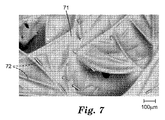
様々な熱可塑性及び/又は熱成形性ポリマーが、高分子層に有用である。例示的な高分子層は、ポリプロピレン及びポリエチレン(例えば、低密度ポリエチレン及び線状低密度ポリエチレン)、ポリウレタン、ポリアミド、ポリブタジエン、ポリカーボネート、ポリスチレン、ポリエステル、コポリマー類、及びこれらのブレンドを含む。高分子層は三次元であり(すなわち、高分子層は一般に、これらの繊維の外側表面にぴったり一致する)、ここで高分子材料は、高分子表面の「z」方向へのトポグラフィー変化が高分子フィルム層の平均厚さを超える全体的な三次元構造を有し、典型的には、適用される主表面内に少なくとも部分的にある(すなわち、主表面の層内を少なくとも部分的に貫通する)(例えば、図7及び8参照、それぞれ繊維81及び82を有する不織布層の主表面上の、それぞれ高分子層71及び81を示す)。三次元高分子層は、典型的には、それが接触する露出された主表面に露出した繊維と密に接触する。典型的には、三次元高分子フィルムと繊維層との間の結合力は、繊維層の結合力よりも大きい。
A variety of thermoplastic and / or thermoformable polymers are useful for the polymer layer. Exemplary polymeric layers include polypropylene and polyethylene (eg, low density polyethylene and linear low density polyethylene), polyurethane, polyamide, polybutadiene, polycarbonate, polystyrene, polyester, copolymers, and blends thereof. The polymer layer is three-dimensional (ie, the polymer layer generally matches the outer surface of these fibers), where the polymer material has a topographic change in the “z” direction of the polymer surface. It has an overall three-dimensional structure that exceeds the average thickness of the polymeric film layer, and is typically at least partially within the applied major surface (ie, at least partially within the major surface layer). (See, for example, FIGS. 7 and 8, polymer layers 71 and 81, respectively, on the major surface of the nonwoven layer with
高分子層を本明細書に記載のマットの製造に提供してもよく、それは例えば、
通常対向する第1及び第2の主表面を有する不織布層であって、無機繊維を含む不織布層を提供する工程と、
かかる不織布層の第2の主表面に真空を適用する工程と、
かかる第1の主表面に第1の高分子層を付着してマットを提供する工程と、を含む方法によるものである。任意に、この方法は、第1の主表面に付着された第1の高分子層に真空を適用する工程と、第2の主表面に第2の高分子層を付着して第2の高分子層を有するマットを提供する工程と、を更に含む。少なくとも第1の高分子層に存在する穿孔を有することが望ましい。このような穿孔は、真空プロセスによる不織布層に第2の高分子層を付着するプロセスを促進する。第1の高分子層に穿孔があることにより、空気が第1の高分子層を通って不織布層を引っ張ることができ、それにより不織布層中で真空を形成し、第2の主表面上に第2の高分子層を引っ張ることができる。
A polymer layer may be provided for the manufacture of the mats described herein, for example
Providing a non-woven fabric layer comprising inorganic fibers, which is a non-woven fabric layer having first and second major surfaces that normally face each other;
Applying a vacuum to the second main surface of the nonwoven layer;
Providing a mat by attaching a first polymer layer to the first main surface. Optionally, the method includes applying a vacuum to the first polymer layer deposited on the first major surface, and depositing a second polymer layer on the second major surface to produce a second high layer. Providing a mat having a molecular layer. It is desirable to have perforations present in at least the first polymer layer. Such perforation facilitates the process of attaching the second polymer layer to the nonwoven layer by a vacuum process. Due to the perforations in the first polymer layer, air can pull the nonwoven layer through the first polymer layer, thereby creating a vacuum in the nonwoven layer on the second major surface. The second polymer layer can be pulled.
例えば、高分子層を通して、少なくとも1つ及び好ましくは複数の真空成形された吸引孔を形成するため、本明細書に記載のマットで用いられる高分子層を穿孔することができる。第1の高分子層を通して形成された孔は、第2の高分子層を付着するとき、真空により第1の高分子層を通して引っ張ることができる。「吸引孔」は、高分子層が無機繊維を含む不織布層の主表面上に配置され、真空でその不織布層の主表面の反対側を引っ張る際に、高分子層を通して形成された孔を指すことができ、一方、高分子層が軟化点まで加熱され、真空により(a)不織布層中の無機繊維と接触する高分子層を引っ張ること、及び(b)高分子フィルムを通る1つ以上の吸引孔を形成することを可能にする。加熱工程は、高分子層中で局部的な融解を引き起こす可能性があり、真空が吸引孔を形成するのを促進する。 For example, the polymer layer used in the mats described herein can be perforated to form at least one and preferably a plurality of vacuum formed suction holes through the polymer layer. The pores formed through the first polymer layer can be pulled through the first polymer layer by vacuum when depositing the second polymer layer. “Suction hole” refers to a hole formed through a polymer layer when the polymer layer is disposed on the main surface of the nonwoven layer containing inorganic fibers and pulled opposite the main surface of the nonwoven layer in a vacuum. While the polymer layer is heated to the softening point, and (a) pulling the polymer layer in contact with the inorganic fibers in the nonwoven layer by vacuum, and (b) one or more passing through the polymer film It makes it possible to form suction holes. The heating process can cause local melting in the polymer layer and promotes vacuum to form suction holes.
高分子層を無機繊維に接触するように引っ張ることで、高分子層を三次元高分子層に形成する結果となる。吸引孔は、典型的には、不織布層の主表面における無機繊維間の空間全体に広がる、高分子層の領域内に形成される。例えば、図7及び8に見られる吸引孔(すなわち、黒点)を参照されたい。高分子層は一定の面積を有し、複数の真空成形された吸引孔を含むことができる。吸引孔は、典型的には高分子層の面積全体に不均一に分散される。各吸引孔は、典型的には異なる孔の形状を有する。各吸引孔は、多くの場合、図7及び8に示すもののように非対称形の孔である。 Pulling the polymer layer in contact with the inorganic fibers results in the polymer layer being formed into a three-dimensional polymer layer. The suction holes are typically formed in a region of the polymer layer that extends over the entire space between the inorganic fibers on the main surface of the nonwoven fabric layer. See, for example, the suction holes (ie, black dots) seen in FIGS. The polymer layer has a certain area and can include a plurality of vacuum-formed suction holes. The suction holes are typically unevenly distributed throughout the area of the polymer layer. Each suction hole typically has a different hole shape. Each suction hole is often an asymmetrical hole, such as that shown in FIGS.
図11を参照すると、このような真空成形された吸引孔の形成の1つのプロセスでは、不織布層又はマット材料であるロール状ウェブ41をほどくためのステーション44、高分子層又はシート材料であるロール状ウェブ42をほどくためのステーション46、不織布材料ウェブ41の上側主表面の上方に高分子材料ウェブを誘導し、配置するためのガイドローラー48、不織布材料ウェブ41の下部に配置される最大3ヶ所の真空ゾーン52a、52b、及び52cを有する真空箱、高分子材料ウェブ42の上方に配置される熱源54(例えば、電気的加熱エレメント)、及びマット材料である得られたウェブ50(すなわち、少なくとも高分子層42及び不織布層41の組み合わせ)をロール状に巻き取るためのステーション60を備える、装置40を利用する。ステーション60はマットウェブ50を引っ張り、それにより個々のウェブ41及び42は加熱ゾーン56を、続いて冷凍、又は冷却ゾーン58を通る。
Referring to FIG. 11, in one process of forming such vacuum formed suction holes, a
不織布ウェブ材料41は、十分に多孔質であり、不織布材料を通して真空を十分に生じさせることが可能で、高分子材料であるウェブが、不織布ウェブ42の上側主表面に対して引っ張り下げられる(すなわち、吸引される)。第1の真空ゾーン52aにより引かれる真空力により、ガイドローラー48を過ぎて運ばれる間、ウェブ41及び42はまとまっている。ウェブ41及び42が加熱ゾーン56を通って運ばれる間、高分子ウェブ42を少なくとも軟化、又は部分的に融解するように、熱源54からの熱が矢印55の方向に放射される。ゾーン56で高分子ウェブ42が軟化及び/又は融解するのと同時に、真空ゾーン52bで生じた真空を制御し、不織布材料の繊維に対して三次元形状に変形させるように、高分子ウェブ42を引っ張らせることができる。特にウェブ42が軟化又は融解される場合、ゾーン52bの真空により、高分子ウェブ42を貫通して吸引孔を形成させることもできる。いったん吸引孔が開口すると、熱源54により加熱された空気を、吸引孔を通って不織布ウェブ材料41に引き込むことができる。この加熱された空気(矢印55を参照)からの更なる熱は、ウェブ42の軟化及び/又は融解を促進でき、それにより、ウェブ42に形成された吸引孔の数量の増加、存在する吸引孔の寸法の拡大、高分子ウェブ42と不織布ウェブ41との間の結合を促進、又はこれらの任意の組み合わせを行う。冷却ゾーン58内の温度は、硬化及び/又は凝固のため、高分子材料ウェブ42を軟化及び/又は融解させるゾーン56のものより十分に低い。ゾーン52cに適用される真空により、ウェブ42の吸引孔を通して矢印59の方向に低温空気が引かれ、事前に加熱されたウェブ41及び42を冷却する。ゾーン52cの真空によりもたらされる冷却効果に加え、従来の冷凍装置又は空調装置の使用により、ゾーン58の冷却を任意に補助することもできる。
The
高分子材料である第1のウェブ42内に真空成形された吸引孔は、第2の高分子層を不織布ウェブ41の別の主表面に結合できるようにする。第2の高分子層の適用には、ステーション60で巻き取られたマットウェブ50のロールをステーション44に配置でき、ウェブ50の向きを、穿孔された高分子ウェブ42が不織布ウェブ41の下方に置かれ、ウェブ41の別の主表面が露出し表向きになるようにする。次いで、上述と同様の方式で装置40を用いて、同一又は異なる高分子材料である別のウェブ42を、露出されたウェブ41の主表面に付着できる。第1のウェブ42内に事前に形成された吸引孔により、ゾーン52a、52b及び52cで生じた真空が、不織布ウェブ41内の真空を引っ張れるようにする。
Suction holes vacuum formed in the
任意に、マットは1つ以上の膨張性層も含み、及び任意に、上述の方法を用いて高分子層を膨張性層の主表面に適用する。 Optionally, the mat also includes one or more expandable layers, and optionally a polymer layer is applied to the major surface of the expandable layer using the methods described above.
任意に、両面接着剤テープを、第1の高分子層の露出した外側主表面の少なくとも一部に貼付する。任意に、両面接着剤テープとして、剥離ライナーが挙げられる。 Optionally, a double-sided adhesive tape is applied to at least a portion of the exposed outer major surface of the first polymer layer. Optionally, the double-sided adhesive tape includes a release liner.
好ましくは、無機繊維層は、少なくとも300g/m2、400g/m2、500g/m2、600g/m2、700g/m2、800g/m2、900g/m2、1300g/m2、2000g/m2、又は更には少なくとも3100g/m2(一部の実施形態では、300g/m2〜8500g/m2の範囲)の坪量を有する。 Preferably, the inorganic fiber layer is at least 300 g / m 2 , 400 g / m 2 , 500 g / m 2 , 600 g / m 2 , 700 g / m 2 , 800 g / m 2 , 900 g / m 2 , 1300 g / m 2 , 2000 g. / m 2, or even (in the embodiment of the part, the range of 300g / m 2 ~8500g / m 2 ) of at least 3100 g / m 2 having a basis weight of.
本明細書に記載の不織布層及びマットは、500℃超で加熱する前の出来上がった状態では、状況に応じ、不織布又はマットの総重量に基づき、7(一部の実施形態では、6、5、4、3、2、1以下、又は更にはゼロ)重量パーセント以下の有機材料を含有する。 The nonwoven layers and mats described herein are 7 (based in some embodiments, 6, 5) in the finished state prior to heating above 500 ° C., depending on the situation, based on the total weight of the nonwoven fabric or mat. 4, 3, 2, 1 or less, or even zero) containing no more than weight percent organic material.
本明細書に記載の不織布層及びマットは、典型的には、直径7.5cmのロッドに破断することなく巻き付けられるよう十分に可撓性がある。マットは、通常、破断又は亀裂することなく取扱われ、汚染防止装置の汚染防止エレメントに巻き付けることができる。汚染防止エレメントに巻き付けられるとき、多層マットの末端を様々な接合部で止めてもよい。 The nonwoven layers and mats described herein are typically flexible enough to be wound around a 7.5 cm diameter rod without breaking. The mat is usually handled without breaking or cracking and can be wrapped around the pollution control element of the pollution control device. When wrapped around a pollution control element, the end of the multilayer mat may be stopped at various joints.
本明細書に記載のマット及び不織布層を、例えばダイカット又はレーザーカット技術を用いて切断できる。出願人らは、ダイカット用器具を用いると、多くの場合、縁部に沿って高分子フィルムと不織布との間の接着品質が劣化することを観察しているため、レーザーカット縁部が好ましい。この部分的層剥離は、マット性能に影響し、性能を低下し得る(露出した縁部での繊維の脱落の増加、マット取り付けプロセスの干渉など)。レーザービームを用いて本明細書に記載のマットからパーツを切断すると、高分子層の層剥離を著しく制限できることが判明した。レーザービームが不織布に含まれる繊維周囲の高分子層を局部的に軟化及び/又は融解するため、レーザービームを用いてパーツを切断した後は、マットの主表面(高分子フィルムを含む)と副表面との間の交点、又は切断中に生じた縁部は封止される。レーザービームはまた、切断中に生じた副表面又は縁部も封止でき、更なる繊維の脱落を防ぐ。 The mat and nonwoven layers described herein can be cut using, for example, die cut or laser cut techniques. Applicants have observed that the use of die-cutting instruments often degrades the quality of adhesion between the polymer film and the nonwoven along the edge, so laser-cut edges are preferred. This partial delamination can affect mat performance and reduce performance (increased fiber shedding at exposed edges, interference with mat attachment process, etc.). It has been found that delamination of the polymer layer can be significantly limited when parts are cut from the mat described herein using a laser beam. In order to locally soften and / or melt the polymer layer around the fiber contained in the nonwoven fabric, the laser beam cuts the part using the laser beam, and then the main surface (including polymer film) and secondary Intersections with the surface, or edges that occur during cutting, are sealed. The laser beam can also seal secondary surfaces or edges that occur during cutting, preventing further fiber shedding.
図9を参照すると、本明細書に記載の例示的なマット(実施例1)のダイカット縁部の走査型電子顕微鏡による倍率200倍のデジタル画像では、高分子層91、繊維92、及び高分子層91のダイカット縁部93を有するマットが示される。図10を参照すると、本明細書に記載の例示的なマット(実施例1)のレーザーカット縁部の走査型電子顕微鏡による倍率200倍のデジタル画像では、高分子層1001、繊維1002を有するマットが示され、及び高分子層1001のレーザーカット縁部1003が示される。
Referring to FIG. 9, in a 200 × digital image of a die cut edge of the exemplary mat described herein (Example 1) with a scanning electron microscope, a
本明細書で使用するとき、本明細書に記載のマットを包囲する布地における「耐火性」とは、450℃を超える軟化点(ASTM C338−93(2008)により決定され、その開示が参照により本明細書に組み込まれる)又は融点のうち少なくとも1つを有する材料を意味する。本明細書に記載のマットを包囲する例示的な耐火クロスとして、ガラス布及びシリカ布が挙げられる。本明細書に記載のマットを包囲する例示的な耐火クロスは、AVS Industries,LLC(New Castle,DE)から商品名「AVS FIBER GLASS FABRICS」、「FLXGLAS HT TREATED FIBERGLASS FABRICS」、及び「AVSIL PLAIN WEAVE SILICA FABRICS」で市販されている。 As used herein, “fire resistance” in the fabric surrounding the mats described herein is determined by the softening point above 450 ° C. (ASTM C338-93 (2008), the disclosure of which is hereby incorporated by reference). Or a material having at least one of melting points, incorporated herein. Exemplary fire resistant cloths surrounding the mats described herein include glass cloth and silica cloth. Exemplary refractory cloths surrounding the mats described herein are trade names “AVS FIBER GLAST FABRICS”, “FLXGLAS HT TREATED FIBERGLASS FABRICS”, and “AVSIL S” from AVS Industries, LLC (New Castle, DE). It is commercially available from SILICA FABRICS.
金属ケーシングは、そのような使用に関して当技術分野にて公知の、ステンレス鋼を含む、材料から作製することができる。 The metal casing can be made of materials known in the art for such use, including stainless steel.
不織布マットは、例えば排気パイプ、汚染防止装置の入口若しくは出口末端円錐部、又は内燃機関エンジンの排気マニフォルドを含む、排気システムの様々な構成成分を断熱する断熱材料として使用することができる。本明細書に記載する不織布マットは、例えば汚染防止装置内にて有用である。汚染防止装置は、典型的には、本明細書に記載の不織布マットと共にケーシング内に実装される汚染防止エレメント(例えば、触媒コンバータ、ディーゼル微粒子フィルタ又は選択的触媒低減エレメント)を含む。二重壁排気部品(例えば、排気パイプ、末端円錐部の末端キャップ、若しくは汚染防止装置の別の部分、及び/又は排気マニフォルド)と、本明細書に記載の不織布マットと、を含む排気システムでは、不織布マットは、二重壁部品の第1の外壁と第2の内壁との間の間隙に実装されてもよい。例示的な実装密度は、約0.1g/cm2〜0.6g/cm2の範囲にある。 Nonwoven mats can be used as thermal insulation materials to insulate various components of the exhaust system, including, for example, exhaust pipes, contamination control device inlet or outlet end cones, or internal combustion engine exhaust manifolds. The nonwoven mats described herein are useful, for example, in a pollution control device. A pollution control device typically includes a pollution control element (eg, a catalytic converter, a diesel particulate filter or a selective catalyst reduction element) mounted in a casing with the nonwoven mat described herein. In an exhaust system comprising a double wall exhaust component (eg, an exhaust pipe, an end cone end cap, or another part of a pollution control device, and / or an exhaust manifold) and a nonwoven mat as described herein. The nonwoven mat may be mounted in the gap between the first outer wall and the second inner wall of the double wall part. Exemplary packing density is in the range of about 0.1g / cm 2 ~0.6g / cm 2 .
本明細書に記載する実装マットで実装することができる例示的な汚染防止エレメントには、ガソリン汚染防止エレメント及びディーゼル汚染防止エレメントが挙げられる。汚染防止エレメントは、触媒コンバータ若しくは微粒子フィルタ、又はトラップであってもよい。触媒コンバータは、金属製ハウジング内に実装されるモノリシック構造体に通常はコーティングされる触媒を含有する。この触媒は、通常、温度要件で動作し、有効であるように適応される。例えば、ガソリンエンジンと共に使用するために、触媒コンバータは、典型的には、400℃〜950℃の範囲の温度で効果的であるべきであるが、ディーゼルエンジン用には、より低い温度(典型的には350℃以下)が一般的である。金属モノリスも時折使用されているが、モノリシック構造体は、典型的にはセラミックである。触媒は、大気汚染を抑制するために、排出ガス中の一酸化炭素及び炭化水素を酸化させ、窒素酸化物を還元する。ガソリンエンジンでは、これらの汚染物質の3つすべては、いわゆる「三元コンバータ」内で同時に反応することができるが、ほとんどのディーゼルエンジンは、ディーゼル酸化触媒コンバータしか備え付けられていない。今日ではその使用がディーゼルエンジンのみに限定される、窒素酸化物を低減する触媒コンバータは、一般に別個の触媒コンバータからなる。ガソリンエンジンで使用する汚染防止エレメントの例としては、例えばCorning Inc(コーニング、ニューヨーク)又はNGK Insulators,LTD.(名古屋、日本)から市販されている菫青石から形成されたもの、又は、例えばEmitec(Lohmar、ドイツ)から市販されている金属モノリスが挙げられる。 Exemplary pollution control elements that can be mounted with the mounting mats described herein include gasoline pollution control elements and diesel pollution control elements. The pollution control element may be a catalytic converter or a particulate filter, or a trap. Catalytic converters contain a catalyst that is normally coated onto a monolithic structure that is mounted in a metal housing. The catalyst is usually adapted to operate and be effective at temperature requirements. For example, for use with gasoline engines, catalytic converters should typically be effective at temperatures in the range of 400 ° C to 950 ° C, but for diesel engines, lower temperatures (typically Is generally 350 ° C. or lower). Metallic monoliths are also used occasionally, but monolithic structures are typically ceramic. In order to suppress air pollution, the catalyst oxidizes carbon monoxide and hydrocarbons in the exhaust gas and reduces nitrogen oxides. In gasoline engines, all three of these pollutants can react simultaneously in a so-called “three-way converter”, but most diesel engines are equipped with only a diesel oxidation catalytic converter. Catalytic converters that reduce nitrogen oxides, whose use is limited to diesel engines today, generally consist of separate catalytic converters. Examples of pollution control elements used in gasoline engines include, for example, Corning Inc (Corning, NY) or NGK Insulators, LTD. Examples thereof include those formed from cordierite commercially available from (Nagoya, Japan) or metal monoliths commercially available from, for example, Emitec (Lohmar, Germany).
好適な選択的触媒低減エレメントは、例えば、Corning,Inc.,Corning,NYから入手可能である。 Suitable selective catalyst reduction elements are described, for example, in Corning, Inc. , Corning, NY.
ディーゼル微粒子フィルタ又はトラップは典型的にウォールフロー型(wall flow)フィルタであり、典型的に多孔性結晶構造のセラミック材料から作製されるハニカム状のモノリシック構造を有する。ハニカム状構造の交互セルは、通常、排気ガスが1つのセルに入り、1つのセルの多孔質壁を強制的に通過させられ、隣接するセルを通って構造体から出て行くように埋め込まれる。この方法で、ディーゼル排気ガスに存在する小さなすす粒子が回収される。菫青石から形成されている好適なディーゼル微粒子フィルタは、例えばCorning Inc.及びNGK Insulators,Inc.から市販されている。炭化ケイ素から形成されているディーゼル微粒子フィルタは、例えばIbiden Co.Ltd.(Japan)から市販されており、例えば2002年2月12日公開のJP 2002047070A号に記載されている。 Diesel particulate filters or traps are typically wall flow filters, which typically have a honeycomb-like monolithic structure made from a ceramic material with a porous crystal structure. Alternating cells of a honeycomb-like structure are typically embedded so that exhaust gas enters one cell and is forced through the porous walls of one cell and exits the structure through adjacent cells. . In this way, small soot particles present in the diesel exhaust are recovered. Suitable diesel particulate filters formed from cordierite are, for example, Corning Inc. And NGK Insulators, Inc. Commercially available. Diesel particulate filters formed from silicon carbide are, for example, Ibiden Co. Ltd .. (Japan), for example, described in JP2002047070A published on February 12, 2002.
本発明の利点及び実施形態は、以下の実施例により更に例示されるが、これらの実施例に列挙したその特定の材料及び量、並びに他の条件及び詳細は、本発明を過度に限定すると解釈されるべきではない。すべての部及び百分率は、特に記載されていない限り、重量に基づく。 The advantages and embodiments of the present invention are further illustrated by the following examples, whose particular materials and amounts listed in these examples, as well as other conditions and details, are to be construed as unduly limiting the present invention. Should not be done. All parts and percentages are on a weight basis unless otherwise stated.
(実施例1)
1ロールの76cm(30インチ)幅、15マイクロメートル(0.006インチ)厚の透明低密度ポリエチレン線状フィルム(FlexSol Packaging(Chicago IL)から商品名「ALTEX」で入手)をほどき、2.54cm(1インチ)間隔で設置される1.3cm(0.5インチ)幅のスロットを8つ有する真空テーブルの上で、66cm(26インチ)幅、2000グラム/平方メートルのウェブである実装マット材料(3M Company(St.Paul,MN)から商品名「INTERAM(商標)MAT MOUNT 1220 NC」で販売される材料)上に積層した。ステンレス鋼のキャリアウェブを用い、フィルム及びマットを真空箱の上方へ移動した。2000ワットの赤外線ランプ(型番SRU 1615HT、Infratech(Gardenia,CA))を2つ用いてフィルムを加熱し、フィルム及びマットを共に積層した。第1のランプはウェブから3.2cm(1.25インチ)につるされており、及び第2のランプは第1のランプに隣接した位置にあり、フィルム表面からつるされている(3インチ(7.6cm))状態で、ランプを真空スロットの上方中央に来るように位置決めした。ラインスピードは2.1メートル/分(7フィート/分)とし、これは、織布層表面に密接するようにフィルムを引っ張り、ランプへの曝露及び室温まで冷却した後、マット表面とフィルムとの間にマットの結合力を超える結合を生じさせるのに十分な真空引き(典型的には約10.2〜20.3kPa(3〜6水銀柱インチ))を伴う。
Example 1
1. Unroll one roll of 76 cm (30 inches) wide, 15 micrometers (0.006 inches) thick transparent low density polyethylene linear film (obtained under the trade name “ALTEX” from FlexSol Packaging (Chicago IL)). Mounting mat material which is a 66 cm (26 inch) wide, 2000 gram per square meter web on a vacuum table with eight 1.3 cm (0.5 inch) wide slots placed at 54 cm (1 inch) intervals (Material sold under the trade name “INTERRAM ™ MAT MOUNT 1220 NC” from 3M Company (St. Paul, MN)). A stainless steel carrier web was used to move the film and mat up the vacuum box. The film was heated using two 2000 watt infrared lamps (model SRU 1615HT, Inflatetech (Gardenia, Calif.)) And the film and mat were laminated together. The first lamp is suspended 1.25 inches (3.2 cm) from the web, and the second lamp is located adjacent to the first lamp and is suspended from the film surface (3 inches ( 7.6 cm)), the lamp was positioned to be centered above the vacuum slot. The line speed was 2.1 meters / minute (7 feet / minute), which pulled the film close to the fabric layer surface, exposed to the lamp and cooled to room temperature, then the mat surface and film With sufficient evacuation (typically about 10.2 to 20.3 kPa (3 to 6 inches of mercury)) to produce a bond in between that exceeds the bond strength of the mat.
実施例1のマット(それぞれ繊維81及び82を有する不織布層の主表面上に、それぞれ高分子層71及び81を有する)を示す図7及び8は、それぞれ倍率が50倍及び200倍である。
7 and 8 showing the mat of Example 1 (having the polymer layers 71 and 81 respectively on the main surface of the nonwoven fabric layer having the
実施例1のマットを、従来の金属製ルールダイ、及びレーザー(381cm/分(150インチ/分)で2キロワット)の両方で切断し、ダイカット縁部及びレーザーカット縁部を得た。図9は、実施例1のマットのダイカット縁部の走査型電子顕微鏡による倍率200倍のデジタル画像であり、高分子層91、繊維92、及び高分子層91のダイカット縁部93を示している。図10は、実施例1のマットのレーザーカット縁部の走査型電子顕微鏡による倍率200倍のデジタル画像であり、高分子層1001、繊維1002、及び高分子層1001のレーザーカット縁部1003を示している。
The mat of Example 1 was cut with both a conventional metal rule die and a laser (2 kilowatts at 381 cm / min (150 inches / min)) to obtain die cut edges and laser cut edges. FIG. 9 is a digital image of a 200 × magnification of the die cut edge of the mat of Example 1 using a scanning electron microscope, showing the
実施例1のマットは、直径7.6cm(3インチ)のロッドに破断することなく巻き付いた。 The mat of Example 1 was wound around a rod having a diameter of 7.6 cm (3 inches) without breaking.
(実施例2)
実施例2を、低密度ポリエチレン線状フィルム(「ALTEX」)の第2の層を下部表面上にも積層した(すなわち、実装マットの両主表面が低密度ポリエチレン線状フィルムで積層された)以外は、実施例1に記載の方法で調製した。更に、ラインスピードを1.8メートル/分(6フィート/分)に下げ、織布層表面に密接するようにフィルムを引っ張り、ランプへの曝露及び室温まで冷却した後、マット表面とフィルムとの間にマットの結合力を超える結合を生じさせるのに十分な真空引きを行った(典型的には約16.9〜37.3kPa(5〜11水銀柱インチ))。
(Example 2)
In Example 2, a second layer of low density polyethylene linear film (“ALTEX”) was also laminated on the lower surface (ie, both major surfaces of the mounting mat were laminated with low density polyethylene linear film). Except for the above, it was prepared by the method described in Example 1. In addition, the line speed was reduced to 1.8 meters / minute (6 feet / minute), the film was pulled in close contact with the fabric layer surface, exposed to the lamp and cooled to room temperature, after which the mat surface and film were Sufficient vacuum was applied to create a bond in between that exceeded the mat's bond strength (typically about 16.9 to 37.3 kPa (5 to 11 inches of mercury)).
実施例2のマットは、直径7.6cm(3インチ)のロッドに破断することなく巻き付いた。 The mat of Example 2 wrapped around a 7.6 cm (3 inch) diameter rod without breaking.
(実施例3)
実施例3を、実装マット材料を5100グラム/平方メートル(3M Companyから商品名「INTERAM(商標)MAT MOUNT 700」で販売される材料)にした以外は、実施例1に記載の方法で調製し、ラインスピードを1.8メートル/分(6フィート/分)とし、織布層表面に密接するようにフィルムを引っ張り、ランプへの曝露及び室温まで冷却した後、マット表面とフィルムとの間にマットの結合力を超える結合を生じさせるのに十分な真空引きを行った(典型的には約16.9〜37.3kPa(5〜11水銀柱インチ))。
(Example 3)
Example 3 was prepared by the method described in Example 1 except that the mounting mat material was 5100 grams / square meter (a material sold by 3M Company under the trade name “INTERRAM ™ MAT MOUNT 700”), The line speed is 1.8 meters / minute (6 feet / minute), the film is pulled close to the fabric layer surface, exposed to lamp and cooled to room temperature, then the mat between the mat surface and the film Sufficient vacuum was applied to produce a bond that exceeded the bond strength (typically about 16.9-37.3 kPa (5-11 inches of mercury)).
実施例3のマットは、直径7.6cm(3インチ)のロッドに破断することなく巻き付いた。 The mat of Example 3 was wound around a 7.6 cm (3 inch) diameter rod without breaking.
(実施例4)
実施例4を、実装マット材料を5800グラム/平方メートル(3M Companyから商品名「INTERAM(商標)MAT MOUNT 7220X」で販売される材料)にした以外は、実施例1に記載の方法で調製し、ラインスピードを1.8メートル/分(6フィート/分)とし、織布層表面に密接するようにフィルムを引っ張り、ランプへの曝露及び室温まで冷却した後、マット表面とフィルムとの間にマットの結合力を超える結合を生じさせるのに十分な真空引きを行った(典型的には約16.9〜37.3kPa(5〜11水銀柱インチ))。
Example 4
Example 4 was prepared by the method described in Example 1 except that the mounting mat material was 5800 grams / square meter (material sold by 3M Company under the trade name “INTERRAM ™ MAT MOUNT 7220X”), The line speed is 1.8 meters / minute (6 feet / minute), the film is pulled close to the fabric layer surface, exposed to lamp and cooled to room temperature, then the mat between the mat surface and the film Sufficient vacuum was applied to produce a bond that exceeded the bond strength (typically about 16.9-37.3 kPa (5-11 inches of mercury)).
実施例4のマットは、直径3インチ(7.6cm)のロッドに破断することなく巻き付いた。 The mat of Example 4 was wound around a 3 inch (7.6 cm) diameter rod without breaking.
(実施例5)
2000グラム/平方メートルを示すINTERAM(商標)Mounting Mat Material 1220NC(3M Company(St.Paul,MN))のウェブを、1.27cm(0.5インチ)幅の6つの真空スロット上方、中央部3.81cm(1.5インチ)上を3.66メートル/分(12フィート/分)で、金属メッシュベルト上を運ぶ。真空スロットによりマット全体で、約40水柱cm(1.16水銀柱インチ(3.93kPa))の圧力差を維持する。0.0015mm(0.0006インチ)厚の線状低密度ポリエチレンフィルム(FlexSol Packaging Corp.(Bunsville,MN))をマット表面上部でほどき、マット表面上方2.54cm(1.0インチ)につるされる31.8cm(15インチ)幅の加熱ランプ(WatLow(St.Louis,MO)のRaymax P1560AX019 0852(460ボルト1800ワット))を用いて、マットに熱接合する。Scotchtrak Heat Tracer非接触測定装置(#M Company(Austin,TX)のモデルIR−18EXL3)で測定するとき、ランプ表面温度を約427℃(800°F)に、ランプ直下の加熱エリアを出た際のマット表面温度を約149℃(300°F)に維持するように、十分なパワーを加熱ランプに供給する。
(Example 5)
A web of INTERRAM ™ Mounting Mat Material 1220NC (3M Company (St. Paul, MN)) showing 2000 grams per square meter is placed above the six vacuum slots 1.27 cm (0.5 inches) in the middle 3. Carry on a metal mesh belt at 3.66 meters / minute (12 feet / minute) over 81 cm (1.5 inches). A vacuum slot maintains a pressure differential of about 40 cm of water (1.16 inches of mercury (3.93 kPa)) across the mat. A 0.0015 mm (0.0006 inch) thick linear low density polyethylene film (FlexSol Packaging Corp. (Bunsville, Minn.)) Is unrolled on top of the mat surface and hung 2.54 cm (1.0 inch) above the mat surface. The 31.8 cm (15 inch) wide heating lamp (RayLow P1560AX019 0852 (460 volts 1800 watts) from WatLow (St. Louis, Mo.)) is used to thermally bond to the mat. When measuring with a Scotchtrak Heat Tracer non-contact measuring device (model IR-18EXL3 of #M Company (Austin, TX)), when the lamp surface temperature is about 427 ° C. (800 ° F.) and the heating area directly under the lamp is exited. Sufficient power is supplied to the heating lamp to maintain a mat surface temperature of about 149 ° C. (300 ° F.).
例示的なマットの実施形態
1.
通常互いが対向する第1及び第2の主表面を有する不織布層であって、無機繊維を含む不織布層と、
第1の主表面を形成する無機繊維の少なくとも一部に接触するように付着する第1の高分子層であって、そこを貫いて形成された、少なくとも1つの真空成形された吸引孔を含む第1の高分子層と、を含むマット。かかる第1の高分子層は、好ましくは三次元高分子層である。
2.かかる第1の高分子層が一定の面積を有し、複数の真空成形された吸引孔を含み、かかる吸引孔が第1の高分子層の面積全体に不均一に分散される、実施形態1に記載のマット。
3.かかる吸引孔のそれぞれが異なる孔の形状を有する、実施形態2に記載のマット。
4.かかる吸引孔のそれぞれが非対称形の孔である、実施形態2又は3に記載のマット。
5.通常互いに対向する第1及び第2の主表面を有する膨張性層と、を更に含み、かかる膨張性層の第1の主表面が不織布層の第2の主表面に付着する、実施形態1〜4のいずれか1つに記載のマット。
6.かかる不織布層が膨張性材料を更に含む不織布膨張性層である、実施形態1〜4のいずれか1つに記載のマット。
7.かかる不織布層が、不織布層の総重量に基づき、7重量パーセント以下の有機含有量を有する、実施形態1〜6のいずれか1つに記載のマット。
8.かかる不織布層が、不織布層の総重量に基づき、1重量パーセント以下の有機含有量を有する、実施形態1〜6のいずれか1つに記載のマット。
9.かかる不織布層が、不織布層の総重量に基づき、ゼロ重量パーセントの有機含有量を有する、実施形態1〜6のいずれか1つに記載のマット。
10.かかる第1の高分子層が、最大35マイクロメートルの平均厚さを有する、実施形態1〜9のいずれか1つに記載のマット。
11.かかる第1の高分子層が、5マイクロメートル〜25マイクロメートルの範囲の平均厚さを有する、実施形態1〜9のいずれか1つに記載のマット。
12.かかる第1の高分子層が、10マイクロメートル〜25マイクロメートルの範囲の平均厚さを有する、実施形態1〜9のいずれか1つに記載のマット。
13.かかる第1の高分子層が、熱可塑性であるポリマー(例えば、ポリプロピレン又はポリエチレンのうち少なくとも1つ)を含む、実施形態1〜12のいずれか1つに記載のマット。
14.不織布層が第1の高分子層と第2の高分子層との間にあるように付着する第2の高分子層を更に含み、かかる第2の高分子層が、そこを貫いて形成された、少なくとも1つの真空成形された吸引孔を含む、実施形態1〜13のいずれか1つに記載のマット。かかる第2の高分子層は、好ましくは三次元高分子層である。
15.かかる第2の高分子層が一定の面積を有し、複数の真空成形された吸引孔を含み、かかる吸引孔が第2の高分子層の面積全体に不均一に分散される、実施形態14に記載のマット。
16.かかる吸引孔のそれぞれが異なる孔の形状を有する、実施形態14又は15に記載のマット。
17.かかる吸引孔のそれぞれが非対称形の孔である、実施形態14〜16のいずれか1つに記載のマット。
18.かかる第2の高分子層が、熱可塑性であるポリマーを含む、実施形態14〜17のいずれか1つに記載のマット。
19.かかる第2の高分子層が、最大25マイクロメートルの平均厚さを有する、実施形態14〜18のいずれか1つに記載のマット。
20.かかる第2の高分子層が、5マイクロメートル〜25マイクロメートルの範囲の平均厚さを有する、実施形態14〜18のいずれか1つに記載のマット。
21.かかる第2の高分子層が、10マイクロメートル〜25マイクロメートルの範囲の平均厚さを有する、実施形態14〜18のいずれか1つに記載のマット。
22.かかる無機繊維が、ガラス繊維の総重量に基づき、合計95重量パーセント以下のSiO2及びAl2O3を含むガラス繊維を含む、実施形態1〜21のいずれか1つに記載のマット。
23.かかる無機繊維が耐火セラミック繊維を含む、実施形態1〜22のいずれか1つに記載のマット。
24.かかる無機繊維が多結晶性セラミック繊維を含む、実施形態1〜23のいずれか1つに記載のマット。
25.かかる無機繊維が生体溶解性繊維を含む、実施形態1〜24のいずれか1つに記載のマット。
26.かかる不織布層が、少なくとも900g/m2の坪量を有する、実施形態1〜25のいずれか1つに記載のマット。
27.かかる不織布層が、800g/m2〜8500g/m2の範囲の坪量を有する、実施形態1〜25のいずれか1つに記載のマット。
28.かかる繊維が少なくとも5マイクロメートルの直径を有する、実施形態1〜27のいずれか1つに記載のマット。
29.かかる不織布層が、ニードルパンチ、ウェットレイドプロセスによる製造、及びドライレイドプロセスによる製造、の少なくとも1つ、又はこれらの任意の組み合わせを施される、実施形態1〜28のいずれか1つに記載のマット。
30.かかる不織布層が、500℃超で加熱する前の出来上がった状態では、マットの総重量に基づき、7重量パーセント以下の有機材料を含有する、実施形態1〜29のいずれか1つに記載のマット。
31.かかる不織布層が、0.05g/cm3〜0.3g/cm3の範囲の出来上がった状態の嵩密度を有する、実施形態1〜30のいずれか1つに記載のマット。
32.かかる不織布層が、3mm〜50mmの範囲の平均厚さを有する、実施形態1〜31のいずれか1つに記載のマット。
33.かかるマットが非膨張性である、実施形態1〜4及び7〜32のいずれか1つに記載のマット。
34.かかるマットがバーミキュライトを含まない、実施形態1〜4及び7〜32のいずれか1つに記載のマット。
35.かかる不織布マットが、直径7.5cmのロッドに破断することなく巻き付けられるよう十分に可撓性がある、実施形態1〜34のいずれか1つに記載のマット。
36.少なくとも1つのレーザーカット縁部を有する、実施形態1〜35のいずれか1つに記載のマット。
37.かかる不織布層の第2の主表面に付着する第1の膨張性層を更に含む、実施形態1〜4及び7〜36のいずれか1つに記載のマット。
38.かかる第1の高分子層が露出した外側主表面を有し、少なくともその一部上に貼付された両面接着剤テープを有する、実施形態1〜37のいずれか1つに記載のマット。
39.かかる両面接着剤テープが剥離ライナーを含む、実施形態38に記載のマット。
40.かかる不織布層が、800g/m2〜3000g/m2の範囲の坪量を有する、実施形態1〜39のいずれか1つに記載のマット。
41.マットを包囲する耐火クロスと組み合わせる、実施形態1〜40のいずれか1つに記載のマット。
Exemplary Mat Embodiments 1.
A non-woven layer having first and second main surfaces that are normally opposed to each other, the non-woven layer comprising inorganic fibers;
A first polymer layer that adheres in contact with at least a portion of the inorganic fibers that form the first major surface, and includes at least one vacuum formed suction hole formed therethrough A mat comprising: a first polymer layer; Such a first polymer layer is preferably a three-dimensional polymer layer.
2. Embodiment 1, wherein the first polymer layer has a certain area, includes a plurality of vacuum-formed suction holes, and the suction holes are unevenly distributed over the entire area of the first polymer layer. The mat described in.
3. The mat of embodiment 2, wherein each of the suction holes has a different hole shape.
4). The mat according to embodiment 2 or 3, wherein each of the suction holes is an asymmetric hole.
5). Embodiments 1 to 1, further comprising an inflatable layer having first and second main surfaces that normally face each other, wherein the first main surface of the intumescent layer adheres to the second main surface of the nonwoven layer. 5. The mat according to any one of 4.
6). The mat according to any one of Embodiments 1 to 4, wherein the non-woven fabric layer is a non-woven expandable layer further containing an expandable material.
7). Embodiment 7. The mat of any one of embodiments 1-6, wherein the nonwoven layer has an organic content of 7 weight percent or less, based on the total weight of the nonwoven layer.
8). Embodiment 7. The mat of any one of embodiments 1-6, wherein the nonwoven layer has an organic content of 1 weight percent or less based on the total weight of the nonwoven layer.
9. The mat of any one of embodiments 1-6, wherein the nonwoven layer has an organic content of zero weight percent, based on the total weight of the nonwoven layer.
10.
11.
12
13.
14 And further comprising a second polymer layer attached such that the nonwoven layer is between the first polymer layer and the second polymer layer, wherein the second polymer layer is formed therethrough.
15.
16. The mat according to
17. Embodiment 17. A mat according to any one of embodiments 14-16, wherein each such suction hole is an asymmetrical hole.
18. Embodiment 18. The mat of any one of
19. Embodiment 19. The mat of any one of embodiments 14-18, wherein the second polymer layer has an average thickness of up to 25 micrometers.
20. Embodiment 19. The mat of any one of embodiments 14-18, wherein the second polymeric layer has an average thickness in the range of 5 micrometers to 25 micrometers.
21. Embodiment 19. A mat according to any one of embodiments 14-18, wherein such second polymeric layer has an average thickness in the range of 10 micrometers to 25 micrometers.
22. Such inorganic fibers, based on the total weight of the glass fibers, including glass fibers comprising SiO 2 and Al 2 O 3 in total of 95 weight percent, mat according to any one of embodiments 1-21.
23. The mat of any one of embodiments 1-22, wherein the inorganic fibers comprise refractory ceramic fibers.
24. The mat according to any one of embodiments 1-23, wherein the inorganic fibers comprise polycrystalline ceramic fibers.
25. The mat according to any one of Embodiments 1 to 24, wherein the inorganic fibers comprise biosoluble fibers.
26. Such nonwoven layer has a basis weight of at least 900 g / m 2, mat according to any one of embodiments 1-25.
27. Mat according to such nonwoven layer having a basis weight in the range of 800g / m 2 ~8500g / m 2 , any one of embodiments 1-25.
28. Embodiment 28. The mat of any one of embodiments 1-27, wherein the fibers have a diameter of at least 5 micrometers.
29. Embodiment 29. The embodiment of any one of embodiments 1-28, wherein the nonwoven layer is subjected to at least one of needle punching, manufacturing by a wet laid process, and manufacturing by a dry laid process, or any combination thereof. mat.
30. The mat of any one of embodiments 1-29, wherein the nonwoven layer contains 7 weight percent or less organic material, based on the total weight of the mat, in a finished state prior to heating above 500 ° C. .
31. The mat of any one of embodiments 1-30, wherein the nonwoven layer has a finished bulk density in the range of 0.05 g / cm 3 to 0.3 g / cm 3 .
32. The mat of any one of embodiments 1-31, wherein the nonwoven layer has an average thickness in the range of 3 mm to 50 mm.
33. 33. A mat according to any one of embodiments 1-4 and 7-32, wherein the mat is non-expandable.
34. The mat according to any one of Embodiments 1-4 and 7-32, wherein the mat does not comprise vermiculite.
35. Embodiment 35. The mat of any one of embodiments 1-34, wherein the nonwoven mat is flexible enough to be wrapped around a 7.5 cm diameter rod without breaking.
36. The mat of any one of embodiments 1-35, having at least one laser cut edge.
37. The mat of any one of embodiments 1-4 and 7-36, further comprising a first expandable layer attached to the second major surface of the nonwoven layer.
38. 38. The mat according to any one of embodiments 1-37, wherein the first polymer layer has an exposed outer main surface and has a double-sided adhesive tape affixed on at least a portion thereof.
39. The mat of embodiment 38, wherein such a double-sided adhesive tape comprises a release liner.
40. Mat according to such nonwoven layer having a basis weight in the range of 800g / m 2 ~3000g / m 2 , any one of embodiments 1-39.
41. 41. A mat according to any one of the embodiments 1-40, in combination with a refractory cloth surrounding the mat.
例示的な汚染防止装置の実施形態
1.マットの実施形態1〜41のいずれか1つに記載のマットと共にケーシング内に実装されている汚染防止エレメントを含む汚染防止装置。
2.汚染エレメントが、触媒コンバータ、ディーゼル微粒子フィルタ又は選択的触媒低減エレメントのうちの1つである、実施形態1に記載の汚染防止装置。
Exemplary Contamination Prevention Device Embodiments 1. A pollution control device comprising a pollution control element mounted in a casing together with the mat according to any one of embodiments 1-41 of the mat.
2. The pollution control device according to embodiment 1, wherein the pollution element is one of a catalytic converter, a diesel particulate filter or a selective catalyst reduction element.
例示的な排気システムの実施形態
1.二重壁排気部品と、実施形態1〜41のいずれか1つに記載のマットと、を含み、かかるマットが二重壁排気部品の壁間の間隙内に配置される、排気システム。
2.かかる二重壁排気部品が排気パイプである、実施形態1に記載の排気システム。
3.かかる二重壁排気部品が、汚染防止装置の末端円錐部である、実施形態1に記載の排気システム。
4.かかる二重壁排気部品が排気マニフォルドである、実施形態1に記載の排気システム。
Exemplary exhaust system embodiments 42. An exhaust system comprising a double wall exhaust component and a mat according to any one of embodiments 1-41, wherein the mat is disposed in a gap between the walls of the double wall exhaust component.
2. The exhaust system of embodiment 1, wherein the double wall exhaust component is an exhaust pipe.
3. The exhaust system of embodiment 1, wherein the double wall exhaust component is a terminal cone of a pollution control device.
4). The exhaust system of embodiment 1, wherein the double wall exhaust component is an exhaust manifold.
例示的な物品の実施形態
1.半径rを有する物体と、
物理的に重複することなく実質的に物体半径の周囲に巻かれる、マットの実施形態1〜41のいずれか1つに記載のマットと、を含む物品。
2.かかるマットが、2πrの99パーセント以内の巻き付け長さを有する、実施形態1に記載の物品。
3.かかるマットが、2πrの98パーセント以内の巻き付け長さを有する、実施形態1に記載の物品。
4.かかるマットが、2πrの95パーセント以内の巻き付け長さを有する、実施形態1に記載の物品。
Exemplary Article Embodiments An object having a radius r;
42. An article comprising the mat according to any one of embodiments 1-41 that is wound substantially around the object radius without physically overlapping.
2. The article of embodiment 1, wherein the mat has a wound length within 99 percent of 2πr.
3. The article of embodiment 1, wherein the mat has a wound length within 98 percent of 2πr.
4). The article of embodiment 1, wherein the mat has a wound length within 95 percent of 2πr.
本発明の範囲及び趣旨から外れることなく、本発明の予測可能な修正及び変更が当業者には自明であろう。本発明は、例証の目的のために本出願において説明された実施形態に限定されるべきではない。 Without departing from the scope and spirit of the invention, foreseeable modifications and alterations of the invention will be apparent to those skilled in the art. The present invention should not be limited to the embodiments described in this application for purposes of illustration.
Claims (11)
通常互いが対向する第1及び第2の主表面を有する不織布層であって、無機繊維を含む不織布層と、
前記第1の主表面を形成する無機繊維の少なくとも一部に接触するように付着する第1の高分子層であって、前記高分子層を貫いて形成された、少なくとも1つの真空成形された吸引孔を含む第1の高分子層と、
前記第1の高分子層と第2の高分子層との間に前記不織布層があるように付着する第2の高分子層と、
を含むマット。 A mat for use in a housing of a pollution control device,
A non-woven layer having first and second main surfaces that are normally opposed to each other, the non-woven layer comprising inorganic fibers;
A first polymer layer adhering in contact with at least a portion of the inorganic fibers forming the first main surface, wherein the at least one vacuum formed formed through the polymer layer; A first polymer layer including suction holes;
A second polymer layer attached so that the nonwoven fabric layer is between the first polymer layer and the second polymer layer;
Including mat.
物理的に重複することなく実質的に前記物体の前記半径の周囲に巻かれる、請求項1〜7のいずれか一項に記載のマットと、を含む、物品。 An object having a radius;
An article comprising: a mat according to any one of claims 1 to 7 wound substantially around the radius of the object without physically overlapping.
通常対向する第1及び第2の主表面を有する不織布層であって、無機繊維を含む不織布層を提供する工程と、
前記第1の主表面に第1の高分子層を適用する工程と、
前記第1の高分子層を通る少なくとも一つの真空成形された穿孔を形成するために、前記不織布層の前記第2の主表面に真空を適用する工程と、
前記不織布層が前記第1の高分子層と第2の高分子層との間になるように、マットに第2の高分子層を適用する工程と、
前記第1の高分子層に真空を適用する工程と、を備え、
前記第2の高分子層を適用するときに、前記第1の高分子層を通る少なくとも一つの真空成形された穿孔は真空により第1の高分子層を通して引っ張ることを可能とする、マットの製造方法。 A method of manufacturing a mat for use in a housing of a pollution control device, comprising:
Providing a non-woven fabric layer comprising inorganic fibers, which is a non-woven fabric layer having first and second major surfaces that normally face each other;
Applying a first polymer layer to the first main surface;
Applying a vacuum to the second major surface of the nonwoven layer to form at least one vacuum formed perforation through the first polymer layer;
Applying a second polymer layer to the mat such that the nonwoven layer is between the first polymer layer and the second polymer layer;
Applying a vacuum to the first polymer layer,
Manufacture of a mat that, when applying the second polymer layer, allows at least one vacuum formed perforation through the first polymer layer to be pulled through the first polymer layer by vacuum. Method.
Applications Claiming Priority (3)
| Application Number | Priority Date | Filing Date | Title |
|---|---|---|---|
| US15985209P | 2009-03-13 | 2009-03-13 | |
| US61/159,852 | 2009-03-13 | ||
| PCT/US2010/026893 WO2010105000A1 (en) | 2009-03-13 | 2010-03-11 | Mat and devices with the same |
Publications (3)
| Publication Number | Publication Date |
|---|---|
| JP2012520399A JP2012520399A (en) | 2012-09-06 |
| JP2012520399A5 JP2012520399A5 (en) | 2013-05-02 |
| JP5881423B2 true JP5881423B2 (en) | 2016-03-09 |
Family
ID=42144850
Family Applications (1)
| Application Number | Title | Priority Date | Filing Date |
|---|---|---|---|
| JP2011554171A Active JP5881423B2 (en) | 2009-03-13 | 2010-03-11 | Mats and equipment with mats |
Country Status (6)
| Country | Link |
|---|---|
| US (1) | US10060324B2 (en) |
| EP (1) | EP2406073B1 (en) |
| JP (1) | JP5881423B2 (en) |
| KR (1) | KR101716912B1 (en) |
| CN (1) | CN102421598B (en) |
| WO (1) | WO2010105000A1 (en) |
Families Citing this family (9)
| Publication number | Priority date | Publication date | Assignee | Title |
|---|---|---|---|---|
| USD665320S1 (en) * | 2011-03-14 | 2012-08-14 | Donna Medved | Tail pipe tip extenders |
| JP6059447B2 (en) * | 2012-04-13 | 2017-01-11 | ニチアス株式会社 | Retaining material for gas processing apparatus, gas processing apparatus and method related thereto |
| RU2686939C2 (en) * | 2013-02-14 | 2019-05-06 | Басф Се | Material and method for sealing empty spaces |
| CN104712445B (en) * | 2013-12-13 | 2019-09-06 | 周向进 | Single fuel compression ignition with light the method for controlling combustion and internal combustion engine mixed |
| EP3172086A1 (en) * | 2014-07-23 | 2017-05-31 | Grandinetti S.r.l. | Element for vehicle thermal insulating, in particular for motor vehicles, and method for manufacturing said element |
| EP2993323B1 (en) * | 2014-09-04 | 2017-07-19 | 3M Innovative Properties Company | Mounting mat for a pollution control element or a chemical reactor |
| CN104826390A (en) * | 2015-04-21 | 2015-08-12 | 安徽凤凰滤清器股份有限公司 | Modified volcanic rock absorption filtering agent, and preparation method thereof |
| EP3091267B1 (en) * | 2015-05-04 | 2020-05-27 | Sjm Co., Ltd. | Flexible conduit element |
| US20210291483A1 (en) * | 2017-11-10 | 2021-09-23 | Chen-Cheng Huang | Composite cloth |
Family Cites Families (41)
| Publication number | Priority date | Publication date | Assignee | Title |
|---|---|---|---|---|
| CA637172A (en) | 1957-08-05 | 1962-02-27 | A. Hatch Robert | Synthetic mica, mica products and method of making |
| US3916057A (en) | 1973-08-31 | 1975-10-28 | Minnesota Mining & Mfg | Intumescent sheet material |
| US4181514A (en) | 1978-02-14 | 1980-01-01 | Huyck Corporation | Stitch knitted filters for high temperature fluids and method of making them |
| US4156533A (en) | 1978-04-28 | 1979-05-29 | Minnesota Mining And Manufacturing Company | High temperature gasket |
| US4521333A (en) | 1983-06-20 | 1985-06-04 | Minnesota Mining And Manufacturing Company | Intumescent silicates having improved stability |
| JPS62121033A (en) * | 1985-11-21 | 1987-06-02 | Nippon Muki Kk | Manufacture of fibrous sound absorbing and heat insulating material having skin layer |
| US5008086A (en) | 1988-10-28 | 1991-04-16 | Minnesota Mining And Manufacturing Company | Erosion resistant mounting composite for catalytic converter |
| US4999168A (en) * | 1989-05-01 | 1991-03-12 | The Carborundum Company | Crack resistant intumescent sheet material |
| JPH0662932B2 (en) | 1990-12-28 | 1994-08-17 | 日本ピラー工業株式会社 | Heat-resistant expansion material |
| DE4107539C2 (en) * | 1991-03-08 | 1996-11-28 | Audi Ag | Insulated pipe |
| JPH0769751A (en) | 1993-08-20 | 1995-03-14 | Minnesota Mining & Mfg Co <3M> | Protection of edge of laminated mat and laminated mat having high temperature sealing material |
| US6245301B1 (en) | 1993-08-20 | 2001-06-12 | 3M Innovative Properties Company | Catalytic converter and diesel particulate filter |
| KR950006447A (en) | 1993-08-20 | 1995-03-21 | 테릴 켄트 쿠 알리 | Mounting mat with high temperature seal |
| JPH0752649A (en) | 1993-08-23 | 1995-02-28 | Kasai Kogyo Co Ltd | Automobile interior trimming parts and manufacture thereof |
| US5686039A (en) | 1995-06-30 | 1997-11-11 | Minnesota Mining And Manufacturing Company | Methods of making a catalytic converter or diesel particulate filter |
| US5882608A (en) * | 1996-06-18 | 1999-03-16 | Minnesota Mining And Manufacturing Company | Hybrid mounting system for pollution control devices |
| US6726884B1 (en) * | 1996-06-18 | 2004-04-27 | 3M Innovative Properties Company | Free-standing internally insulating liner |
| US6923942B1 (en) | 1997-05-09 | 2005-08-02 | 3M Innovative Properties Company | Compressible preform insulating liner |
| GB9723111D0 (en) * | 1997-11-03 | 1998-01-07 | Ici Plc | Composite mat |
| AT407158B (en) * | 1998-09-04 | 2001-01-25 | Dsm Fine Chem Austria Gmbh | INTUMESCENT LAMINATES WITH HIGH THERMAL RESISTANCE RESISTORS CONTAINING MOST PHOSPHORIC ACID AND HEXAMETHOXYMETHYLMELAMINE |
| US6551951B1 (en) | 1999-03-19 | 2003-04-22 | Johns Manville International, Inc. | Burn through resistant nonwoven mat, barrier, and insulation system |
| US20010018306A1 (en) * | 1999-03-22 | 2001-08-30 | Jones Damon Lee | Vacuum formed coated fibrous mat and laminate structures made therefrom |
| JP2000343634A (en) * | 1999-06-07 | 2000-12-12 | Mitsubishi Chemicals Corp | Heat resistant mat |
| JP2001012237A (en) * | 1999-06-24 | 2001-01-16 | Toyota Motor Corp | Catalyst holding member |
| JP2002047070A (en) | 2000-07-31 | 2002-02-12 | Ibiden Co Ltd | Ceramics structure |
| JP2002066331A (en) | 2000-08-25 | 2002-03-05 | Nichias Corp | Catalyst carrier holding member, its production process and catalytic converter |
| DE60230603D1 (en) | 2002-07-31 | 2009-02-12 | 3M Innovative Properties Co | Mat for the storage of a monolithic cleaning device in an exhaust gas purification device for the treatment of exhaust gases of a diesel internal combustion engine |
| JP4309349B2 (en) * | 2002-09-30 | 2009-08-05 | ユニフラックス ワン リミテッド ライアビリティ カンパニー | Exhaust gas treatment apparatus and method for manufacturing the same |
| JP4805808B2 (en) | 2003-01-22 | 2011-11-02 | スリーエム イノベイティブ プロパティズ カンパニー | Molded three-dimensional insulator |
| EP1464800A1 (en) * | 2003-04-02 | 2004-10-06 | 3M Innovative Properties Company | Exhaust system component having insulated double wall |
| US7465690B2 (en) * | 2003-06-19 | 2008-12-16 | Umicore Ag & Co. Kg | Methods for making a catalytic element, the catalytic element made therefrom, and catalyzed particulate filters |
| EP1495807A1 (en) | 2003-06-30 | 2005-01-12 | 3M Innovative Properties Company | Mounting mat for mounting monolith in a pollution control device |
| US7550118B2 (en) * | 2004-04-14 | 2009-06-23 | 3M Innovative Properties Company | Multilayer mats for use in pollution control devices |
| US7645426B2 (en) * | 2004-04-14 | 2010-01-12 | 3M Innovative Properties Company | Sandwich hybrid mounting mat |
| EP1825109B1 (en) | 2004-11-18 | 2018-09-12 | 3M Innovative Properties Company | Method of cutting an inorganic fiber sheet material for a pollution cotrol device |
| WO2006065534A1 (en) | 2004-12-13 | 2006-06-22 | 3M Innovative Properties Company | Mounting mats and pollution control devices using same |
| JP4665618B2 (en) * | 2005-06-10 | 2011-04-06 | イビデン株式会社 | Manufacturing method of holding sealing material |
| JP5014113B2 (en) * | 2007-01-26 | 2012-08-29 | イビデン株式会社 | Sheet material, method for manufacturing the same, exhaust gas treatment device, and silencer |
| EP1953357B1 (en) * | 2007-01-26 | 2009-08-26 | Ibiden Co., Ltd. | Sheet member and manufacturing method thereof, exhaust gas treating apparatus and manufacturing method thereof, and silencing device |
| EP2136994B1 (en) | 2007-04-03 | 2018-08-22 | Dow Global Technologies LLC | Hot film lamination (vacuum assisted) for carpet backing applications |
| CN101730788B (en) | 2007-06-13 | 2013-06-19 | 3M创新有限公司 | Erosion resistant mounting materal and method of making and using the same |
-
2010
- 2010-03-11 EP EP10709625.7A patent/EP2406073B1/en active Active
- 2010-03-11 US US13/255,000 patent/US10060324B2/en active Active
- 2010-03-11 WO PCT/US2010/026893 patent/WO2010105000A1/en active Application Filing
- 2010-03-11 CN CN201080020079.4A patent/CN102421598B/en active Active
- 2010-03-11 JP JP2011554171A patent/JP5881423B2/en active Active
- 2010-03-11 KR KR1020117023953A patent/KR101716912B1/en active IP Right Grant
Also Published As
| Publication number | Publication date |
|---|---|
| CN102421598A (en) | 2012-04-18 |
| WO2010105000A1 (en) | 2010-09-16 |
| CN102421598B (en) | 2014-12-17 |
| US20110314780A1 (en) | 2011-12-29 |
| JP2012520399A (en) | 2012-09-06 |
| EP2406073A1 (en) | 2012-01-18 |
| EP2406073B1 (en) | 2020-04-22 |
| KR20110127269A (en) | 2011-11-24 |
| KR101716912B1 (en) | 2017-03-15 |
| US10060324B2 (en) | 2018-08-28 |
Similar Documents
| Publication | Publication Date | Title |
|---|---|---|
| JP5881423B2 (en) | Mats and equipment with mats | |
| ES2237962T3 (en) | ESTERA OF INORGANIC NON-INTUMISCENT FIBERS AMORFA FOR LOW TEMPERATURE EXHAUST GAS TREATMENT DEVICES. | |
| JP2011080478A (en) | Mounting mat for mounting monolith in pollution control device | |
| WO2011019394A1 (en) | Multiple layer substrate support and exhaust gas treatment device | |
| JP6375268B2 (en) | Non-woven mat | |
| JP6336237B2 (en) | Mounting mat and antifouling device having mounting mat | |
| KR101706806B1 (en) | Non-woven mat and pollution control device with the same | |
| US9358749B2 (en) | Tubular, continuous, seamless, compressible, resilient mounting articles and pollution control devices comprising the same | |
| JP7186098B2 (en) | mat material |
Legal Events
| Date | Code | Title | Description |
|---|---|---|---|
| A521 | Request for written amendment filed |
Free format text: JAPANESE INTERMEDIATE CODE: A523 Effective date: 20130226 |
|
| A621 | Written request for application examination |
Free format text: JAPANESE INTERMEDIATE CODE: A621 Effective date: 20130226 |
|
| A977 | Report on retrieval |
Free format text: JAPANESE INTERMEDIATE CODE: A971007 Effective date: 20140423 |
|
| A131 | Notification of reasons for refusal |
Free format text: JAPANESE INTERMEDIATE CODE: A131 Effective date: 20140527 |
|
| A601 | Written request for extension of time |
Free format text: JAPANESE INTERMEDIATE CODE: A601 Effective date: 20140827 |
|
| A602 | Written permission of extension of time |
Free format text: JAPANESE INTERMEDIATE CODE: A602 Effective date: 20140903 |
|
| A601 | Written request for extension of time |
Free format text: JAPANESE INTERMEDIATE CODE: A601 Effective date: 20140929 |
|
| A602 | Written permission of extension of time |
Free format text: JAPANESE INTERMEDIATE CODE: A602 Effective date: 20141006 |
|
| A601 | Written request for extension of time |
Free format text: JAPANESE INTERMEDIATE CODE: A601 Effective date: 20141027 |
|
| A602 | Written permission of extension of time |
Free format text: JAPANESE INTERMEDIATE CODE: A602 Effective date: 20141104 |
|
| A521 | Request for written amendment filed |
Free format text: JAPANESE INTERMEDIATE CODE: A523 Effective date: 20141126 |
|
| A131 | Notification of reasons for refusal |
Free format text: JAPANESE INTERMEDIATE CODE: A131 Effective date: 20150602 |
|
| A601 | Written request for extension of time |
Free format text: JAPANESE INTERMEDIATE CODE: A601 Effective date: 20150902 |
|
| A601 | Written request for extension of time |
Free format text: JAPANESE INTERMEDIATE CODE: A601 Effective date: 20151002 |
|
| A601 | Written request for extension of time |
Free format text: JAPANESE INTERMEDIATE CODE: A601 Effective date: 20151102 |
|
| A521 | Request for written amendment filed |
Free format text: JAPANESE INTERMEDIATE CODE: A523 Effective date: 20151201 |
|
| TRDD | Decision of grant or rejection written | ||
| A01 | Written decision to grant a patent or to grant a registration (utility model) |
Free format text: JAPANESE INTERMEDIATE CODE: A01 Effective date: 20160105 |
|
| A61 | First payment of annual fees (during grant procedure) |
Free format text: JAPANESE INTERMEDIATE CODE: A61 Effective date: 20160202 |
|
| R150 | Certificate of patent or registration of utility model |
Ref document number: 5881423 Country of ref document: JP Free format text: JAPANESE INTERMEDIATE CODE: R150 |
|
| R250 | Receipt of annual fees |
Free format text: JAPANESE INTERMEDIATE CODE: R250 |
|
| R250 | Receipt of annual fees |
Free format text: JAPANESE INTERMEDIATE CODE: R250 |
|
| R250 | Receipt of annual fees |
Free format text: JAPANESE INTERMEDIATE CODE: R250 |
|
| R250 | Receipt of annual fees |
Free format text: JAPANESE INTERMEDIATE CODE: R250 |
|
| R250 | Receipt of annual fees |
Free format text: JAPANESE INTERMEDIATE CODE: R250 |
|
| R250 | Receipt of annual fees |
Free format text: JAPANESE INTERMEDIATE CODE: R250 |