JP5879337B2 - Case accessories for portable electronic devices and related systems and methods - Google Patents
Case accessories for portable electronic devices and related systems and methods Download PDFInfo
- Publication number
- JP5879337B2 JP5879337B2 JP2013514251A JP2013514251A JP5879337B2 JP 5879337 B2 JP5879337 B2 JP 5879337B2 JP 2013514251 A JP2013514251 A JP 2013514251A JP 2013514251 A JP2013514251 A JP 2013514251A JP 5879337 B2 JP5879337 B2 JP 5879337B2
- Authority
- JP
- Japan
- Prior art keywords
- case
- ped
- holder
- panel
- support
- Prior art date
- Legal status (The legal status is an assumption and is not a legal conclusion. Google has not performed a legal analysis and makes no representation as to the accuracy of the status listed.)
- Active
Links
- 238000000034 method Methods 0.000 title description 9
- 230000007246 mechanism Effects 0.000 claims description 178
- 238000003860 storage Methods 0.000 claims description 31
- 239000000463 material Substances 0.000 claims description 17
- 239000002783 friction material Substances 0.000 claims 2
- 238000001650 pulsed electrochemical detection Methods 0.000 description 352
- 230000008878 coupling Effects 0.000 description 115
- 238000010168 coupling process Methods 0.000 description 115
- 238000005859 coupling reaction Methods 0.000 description 115
- 239000000853 adhesive Substances 0.000 description 19
- 230000001070 adhesive effect Effects 0.000 description 19
- 230000000295 complement effect Effects 0.000 description 13
- 230000003993 interaction Effects 0.000 description 8
- 229920001971 elastomer Polymers 0.000 description 6
- 239000005060 rubber Substances 0.000 description 6
- 230000007704 transition Effects 0.000 description 6
- 230000008859 change Effects 0.000 description 5
- 239000004033 plastic Substances 0.000 description 5
- 229920003023 plastic Polymers 0.000 description 5
- 239000002184 metal Substances 0.000 description 4
- 229920001410 Microfiber Polymers 0.000 description 3
- 238000004140 cleaning Methods 0.000 description 3
- 210000000245 forearm Anatomy 0.000 description 3
- 239000003658 microfiber Substances 0.000 description 3
- 238000000926 separation method Methods 0.000 description 3
- 230000000087 stabilizing effect Effects 0.000 description 3
- 244000043261 Hevea brasiliensis Species 0.000 description 2
- 239000011111 cardboard Substances 0.000 description 2
- 239000013013 elastic material Substances 0.000 description 2
- 239000004744 fabric Substances 0.000 description 2
- 239000010985 leather Substances 0.000 description 2
- 239000002649 leather substitute Substances 0.000 description 2
- 238000004519 manufacturing process Methods 0.000 description 2
- 229920003052 natural elastomer Polymers 0.000 description 2
- 229920001194 natural rubber Polymers 0.000 description 2
- 230000002265 prevention Effects 0.000 description 2
- 230000001681 protective effect Effects 0.000 description 2
- 238000004904 shortening Methods 0.000 description 2
- 239000007779 soft material Substances 0.000 description 2
- 125000000391 vinyl group Chemical group [H]C([*])=C([H])[H] 0.000 description 2
- 229920002554 vinyl polymer Polymers 0.000 description 2
- 239000004677 Nylon Substances 0.000 description 1
- 210000001015 abdomen Anatomy 0.000 description 1
- 238000005452 bending Methods 0.000 description 1
- 239000013536 elastomeric material Substances 0.000 description 1
- 239000012530 fluid Substances 0.000 description 1
- 230000005484 gravity Effects 0.000 description 1
- 238000007373 indentation Methods 0.000 description 1
- 239000007788 liquid Substances 0.000 description 1
- 230000004048 modification Effects 0.000 description 1
- 238000012986 modification Methods 0.000 description 1
- 229920001778 nylon Polymers 0.000 description 1
- 230000002093 peripheral effect Effects 0.000 description 1
- 239000002985 plastic film Substances 0.000 description 1
- 229920001084 poly(chloroprene) Polymers 0.000 description 1
- 229920001296 polysiloxane Polymers 0.000 description 1
- 238000003825 pressing Methods 0.000 description 1
- 230000002787 reinforcement Effects 0.000 description 1
- 230000000717 retained effect Effects 0.000 description 1
- 238000006748 scratching Methods 0.000 description 1
- 230000002393 scratching effect Effects 0.000 description 1
- 239000010454 slate Substances 0.000 description 1
- 239000007787 solid Substances 0.000 description 1
- 239000012780 transparent material Substances 0.000 description 1
- 230000000007 visual effect Effects 0.000 description 1
Images


Classifications
-
- G—PHYSICS
- G06—COMPUTING; CALCULATING OR COUNTING
- G06F—ELECTRIC DIGITAL DATA PROCESSING
- G06F1/00—Details not covered by groups G06F3/00 - G06F13/00 and G06F21/00
- G06F1/16—Constructional details or arrangements
-
- G—PHYSICS
- G06—COMPUTING; CALCULATING OR COUNTING
- G06F—ELECTRIC DIGITAL DATA PROCESSING
- G06F1/00—Details not covered by groups G06F3/00 - G06F13/00 and G06F21/00
- G06F1/16—Constructional details or arrangements
- G06F1/1613—Constructional details or arrangements for portable computers
- G06F1/1632—External expansion units, e.g. docking stations
-
- G—PHYSICS
- G06—COMPUTING; CALCULATING OR COUNTING
- G06F—ELECTRIC DIGITAL DATA PROCESSING
- G06F1/00—Details not covered by groups G06F3/00 - G06F13/00 and G06F21/00
- G06F1/16—Constructional details or arrangements
- G06F1/1613—Constructional details or arrangements for portable computers
- G06F1/1633—Constructional details or arrangements of portable computers not specific to the type of enclosures covered by groups G06F1/1615 - G06F1/1626
-
- A—HUMAN NECESSITIES
- A45—HAND OR TRAVELLING ARTICLES
- A45C—PURSES; LUGGAGE; HAND CARRIED BAGS
- A45C11/00—Receptacles for purposes not provided for in groups A45C1/00-A45C9/00
-
- F—MECHANICAL ENGINEERING; LIGHTING; HEATING; WEAPONS; BLASTING
- F16—ENGINEERING ELEMENTS AND UNITS; GENERAL MEASURES FOR PRODUCING AND MAINTAINING EFFECTIVE FUNCTIONING OF MACHINES OR INSTALLATIONS; THERMAL INSULATION IN GENERAL
- F16M—FRAMES, CASINGS OR BEDS OF ENGINES, MACHINES OR APPARATUS, NOT SPECIFIC TO ENGINES, MACHINES OR APPARATUS PROVIDED FOR ELSEWHERE; STANDS; SUPPORTS
- F16M11/00—Stands or trestles as supports for apparatus or articles placed thereon Stands for scientific apparatus such as gravitational force meters
- F16M11/02—Heads
- F16M11/04—Means for attachment of apparatus; Means allowing adjustment of the apparatus relatively to the stand
- F16M11/06—Means for attachment of apparatus; Means allowing adjustment of the apparatus relatively to the stand allowing pivoting
- F16M11/10—Means for attachment of apparatus; Means allowing adjustment of the apparatus relatively to the stand allowing pivoting around a horizontal axis
- F16M11/105—Means for attachment of apparatus; Means allowing adjustment of the apparatus relatively to the stand allowing pivoting around a horizontal axis the horizontal axis being the roll axis, e.g. for creating a landscape-portrait rotation
-
- F—MECHANICAL ENGINEERING; LIGHTING; HEATING; WEAPONS; BLASTING
- F16—ENGINEERING ELEMENTS AND UNITS; GENERAL MEASURES FOR PRODUCING AND MAINTAINING EFFECTIVE FUNCTIONING OF MACHINES OR INSTALLATIONS; THERMAL INSULATION IN GENERAL
- F16M—FRAMES, CASINGS OR BEDS OF ENGINES, MACHINES OR APPARATUS, NOT SPECIFIC TO ENGINES, MACHINES OR APPARATUS PROVIDED FOR ELSEWHERE; STANDS; SUPPORTS
- F16M11/00—Stands or trestles as supports for apparatus or articles placed thereon Stands for scientific apparatus such as gravitational force meters
- F16M11/20—Undercarriages with or without wheels
- F16M11/2007—Undercarriages with or without wheels comprising means allowing pivoting adjustment
- F16M11/2021—Undercarriages with or without wheels comprising means allowing pivoting adjustment around a horizontal axis
-
- F—MECHANICAL ENGINEERING; LIGHTING; HEATING; WEAPONS; BLASTING
- F16—ENGINEERING ELEMENTS AND UNITS; GENERAL MEASURES FOR PRODUCING AND MAINTAINING EFFECTIVE FUNCTIONING OF MACHINES OR INSTALLATIONS; THERMAL INSULATION IN GENERAL
- F16M—FRAMES, CASINGS OR BEDS OF ENGINES, MACHINES OR APPARATUS, NOT SPECIFIC TO ENGINES, MACHINES OR APPARATUS PROVIDED FOR ELSEWHERE; STANDS; SUPPORTS
- F16M11/00—Stands or trestles as supports for apparatus or articles placed thereon Stands for scientific apparatus such as gravitational force meters
- F16M11/20—Undercarriages with or without wheels
- F16M11/2007—Undercarriages with or without wheels comprising means allowing pivoting adjustment
- F16M11/2035—Undercarriages with or without wheels comprising means allowing pivoting adjustment in more than one direction
- F16M11/2078—Undercarriages with or without wheels comprising means allowing pivoting adjustment in more than one direction with ball-joint
-
- F—MECHANICAL ENGINEERING; LIGHTING; HEATING; WEAPONS; BLASTING
- F16—ENGINEERING ELEMENTS AND UNITS; GENERAL MEASURES FOR PRODUCING AND MAINTAINING EFFECTIVE FUNCTIONING OF MACHINES OR INSTALLATIONS; THERMAL INSULATION IN GENERAL
- F16M—FRAMES, CASINGS OR BEDS OF ENGINES, MACHINES OR APPARATUS, NOT SPECIFIC TO ENGINES, MACHINES OR APPARATUS PROVIDED FOR ELSEWHERE; STANDS; SUPPORTS
- F16M13/00—Other supports for positioning apparatus or articles; Means for steadying hand-held apparatus or articles
- F16M13/005—Other supports for positioning apparatus or articles; Means for steadying hand-held apparatus or articles integral with the apparatus or articles to be supported
-
- F—MECHANICAL ENGINEERING; LIGHTING; HEATING; WEAPONS; BLASTING
- F16—ENGINEERING ELEMENTS AND UNITS; GENERAL MEASURES FOR PRODUCING AND MAINTAINING EFFECTIVE FUNCTIONING OF MACHINES OR INSTALLATIONS; THERMAL INSULATION IN GENERAL
- F16M—FRAMES, CASINGS OR BEDS OF ENGINES, MACHINES OR APPARATUS, NOT SPECIFIC TO ENGINES, MACHINES OR APPARATUS PROVIDED FOR ELSEWHERE; STANDS; SUPPORTS
- F16M13/00—Other supports for positioning apparatus or articles; Means for steadying hand-held apparatus or articles
- F16M13/04—Other supports for positioning apparatus or articles; Means for steadying hand-held apparatus or articles for supporting on, or holding steady relative to, a person, e.g. by chains, e.g. rifle butt or pistol grip supports, supports attached to the chest or head
-
- G—PHYSICS
- G06—COMPUTING; CALCULATING OR COUNTING
- G06F—ELECTRIC DIGITAL DATA PROCESSING
- G06F1/00—Details not covered by groups G06F3/00 - G06F13/00 and G06F21/00
- G06F1/16—Constructional details or arrangements
- G06F1/1613—Constructional details or arrangements for portable computers
-
- G—PHYSICS
- G06—COMPUTING; CALCULATING OR COUNTING
- G06F—ELECTRIC DIGITAL DATA PROCESSING
- G06F1/00—Details not covered by groups G06F3/00 - G06F13/00 and G06F21/00
- G06F1/16—Constructional details or arrangements
- G06F1/1613—Constructional details or arrangements for portable computers
- G06F1/1626—Constructional details or arrangements for portable computers with a single-body enclosure integrating a flat display, e.g. Personal Digital Assistants [PDAs]
-
- G—PHYSICS
- G06—COMPUTING; CALCULATING OR COUNTING
- G06F—ELECTRIC DIGITAL DATA PROCESSING
- G06F1/00—Details not covered by groups G06F3/00 - G06F13/00 and G06F21/00
- G06F1/16—Constructional details or arrangements
- G06F1/1613—Constructional details or arrangements for portable computers
- G06F1/1633—Constructional details or arrangements of portable computers not specific to the type of enclosures covered by groups G06F1/1615 - G06F1/1626
- G06F1/1656—Details related to functional adaptations of the enclosure, e.g. to provide protection against EMI, shock, water, or to host detachable peripherals like a mouse or removable expansions units like PCMCIA cards, or to provide access to internal components for maintenance or to removable storage supports like CDs or DVDs, or to mechanically mount accessories
- G06F1/166—Details related to functional adaptations of the enclosure, e.g. to provide protection against EMI, shock, water, or to host detachable peripherals like a mouse or removable expansions units like PCMCIA cards, or to provide access to internal components for maintenance or to removable storage supports like CDs or DVDs, or to mechanically mount accessories related to integrated arrangements for adjusting the position of the main body with respect to the supporting surface, e.g. legs for adjusting the tilt angle
-
- G—PHYSICS
- G11—INFORMATION STORAGE
- G11B—INFORMATION STORAGE BASED ON RELATIVE MOVEMENT BETWEEN RECORD CARRIER AND TRANSDUCER
- G11B33/00—Constructional parts, details or accessories not provided for in the other groups of this subclass
- G11B33/14—Reducing influence of physical parameters, e.g. temperature change, moisture, dust
- G11B33/1446—Reducing contamination, e.g. by dust, debris
-
- H—ELECTRICITY
- H05—ELECTRIC TECHNIQUES NOT OTHERWISE PROVIDED FOR
- H05K—PRINTED CIRCUITS; CASINGS OR CONSTRUCTIONAL DETAILS OF ELECTRIC APPARATUS; MANUFACTURE OF ASSEMBLAGES OF ELECTRICAL COMPONENTS
- H05K5/00—Casings, cabinets or drawers for electric apparatus
- H05K5/02—Details
- H05K5/0217—Mechanical details of casings
- H05K5/0226—Hinges
-
- A—HUMAN NECESSITIES
- A45—HAND OR TRAVELLING ARTICLES
- A45C—PURSES; LUGGAGE; HAND CARRIED BAGS
- A45C15/00—Purses, bags, luggage or other receptacles covered by groups A45C1/00 - A45C11/00, combined with other objects or articles
-
- A—HUMAN NECESSITIES
- A45—HAND OR TRAVELLING ARTICLES
- A45C—PURSES; LUGGAGE; HAND CARRIED BAGS
- A45C11/00—Receptacles for purposes not provided for in groups A45C1/00-A45C9/00
- A45C2011/002—Receptacles for purposes not provided for in groups A45C1/00-A45C9/00 for portable handheld communication devices, e.g. mobile phone, pager, beeper, PDA, smart phone
-
- A—HUMAN NECESSITIES
- A45—HAND OR TRAVELLING ARTICLES
- A45C—PURSES; LUGGAGE; HAND CARRIED BAGS
- A45C11/00—Receptacles for purposes not provided for in groups A45C1/00-A45C9/00
- A45C2011/003—Receptacles for purposes not provided for in groups A45C1/00-A45C9/00 for portable computing devices, e.g. laptop, tablet, netbook, game boy, navigation system, calculator
-
- G—PHYSICS
- G06—COMPUTING; CALCULATING OR COUNTING
- G06F—ELECTRIC DIGITAL DATA PROCESSING
- G06F2200/00—Indexing scheme relating to G06F1/04 - G06F1/32
- G06F2200/16—Indexing scheme relating to G06F1/16 - G06F1/18
- G06F2200/163—Indexing scheme relating to constructional details of the computer
- G06F2200/1633—Protecting arrangement for the entire housing of the computer
Description
本発明は、概して、携帯電子機器に、及び、より詳しくは、携帯電子機器用のケースアクセサリ(付属品)に関する。 The present invention relates generally to portable electronic devices, and more particularly to case accessories for portable electronic devices.
ノートブック型及びタブレット型のコンピュータ、タブレット型メディア端末(例えば、Apple(登録商標)のiPad(登録商標))、eReader、携帯型情報端末(PDA)及びスマートフォン等の携帯電子機器(PED:portable electronic device)の増加は、かつて部屋全体を占めた初期のコンピュータの計算能力よりも高い計算能力をユーザーに与えた。この携帯可能な計算能力は、個人分野及びビジネス分野の双方においてモバイル機器の生産性を向上させた。 Portable electronic devices (PED: portable electronic devices such as notebook computers and tablet computers, tablet media terminals (for example, Apple (registered trademark) iPad (registered trademark)), eReaders, portable information terminals (PDA), and smartphones The increase in device) gave users more computing power than the computing power of the early computers that once occupied the whole room. This portable computing power has increased the productivity of mobile devices in both personal and business areas.
しかし、PEDはその携帯性に起因してダメージを受けやすい。さらに、PEDはさまざまな表示向き(例えば、縦長表示及び/又は横長表示)で見ることができるが、複数の表示向きで簡単に使用できるよう構成されていない場合がある。 However, PED is susceptible to damage due to its portability. Further, although the PED can be viewed in various display orientations (eg, portrait and / or landscape), it may not be configured for easy use in multiple display orientations.
本発明の実施形態は、PEDをダメージから保護するための、PED用の付属ケースを提供する。いくつかの実施形態において、付属ケースはPEDを囲い、また少なくとも2つの表示向きにして回転可能に支持するよう構成することができる。さまざまな実施形態において、ケースは閉じた状態でPEDを包囲及び保護し、また開いた状態で、PEDを直立支持及び/又は立て掛け支持(すなわち、下支え)をするよう構成することができる。 Embodiments of the present invention provide an accessory case for PED to protect the PED from damage. In some embodiments, the accessory case can be configured to surround the PED and to rotatably support it in at least two display orientations. In various embodiments, the case can be configured to enclose and protect the PED in the closed state and to support the PED in an upright and / or standing (ie, underhang) state in the open state.
本発明の実施形態は図面を参照することで、最もよく理解することができるであろう。場合によっては、類似特徴部分は、同一参照符号を付す場合がある。本発明のコンポーネントは、一般的に説明され、ここにおいて図示されるように、さまざまな構成に配置及び設計できることは容易に理解されるであろう。このように、装置の実施形態の以下のより詳しい説明は本発明の権利範囲を狭めることを意図するものではなく、本発明のあり得る実施形態の代表にすぎない。場合によっては、周知の構造、材料又は動作は、詳細に示さない、又は説明しない。 Embodiments of the present invention may be best understood with reference to the drawings. In some cases, similar features may be assigned the same reference numerals. It will be readily appreciated that the components of the present invention are generally described and can be arranged and designed in a variety of configurations, as illustrated herein. Thus, the following more detailed description of device embodiments is not intended to narrow the scope of the invention, but is merely representative of possible embodiments of the invention. In some instances, well-known structures, materials or operations are not shown or described in detail.
図1〜4は、PED102を見易くするために使用することができるPED102用のケース100を示す。ここに示すケース100は、ホルダ、スリーブ、マウントなどと称することができ、本明細書での使用においては、必ずしも容器収納する又は保持する機能を意味するものではないが、ケース100のいくつかの実施形態ではそのような機能を有する場合もある。PED102は任意の携帯電子機器とすることができ、例えば、ノート型コンピュータ、電子ブックリーダー(例えば、Amazon(登録商標)のKindle(登録商標))、スマートフォン(例えば、Apple(登録商標)のiPhone(登録商標)、Motorola(登録商標)のDroid(登録商標)、BlackBerry(登録商標)のStorm(登録商標))、及び/又はタブレット型コンピュータ若しくはタブレット型端末(例えば、Apple(登録商標)のiPad(登録商標)、RIM Playbook(登録商標)、HP(登録商標)のSlate、Samsung(登録商標)のGalaxy(登録商標)タブレット)がある。
1-4 show a
ケース100は、PED102を収容するよう構成することができ、さらに、PED102を保持し、持ち運び、また保護するよう機能することができる。PED102は、その前面及び/背面に、縦長表示又は横長表示のいずれの向きにおいても見ることができるディスプレイ104、ユーザー入力部(図示せず)、及びデータ入力/出力ポート(図示せず)を有することができる。いくつかの実施形態において、PED102がケース100内に配置されている間、ケース100は、PED102のユーザーが、ディスプレイ104、ユーザー入力部、データ入力/出力ポートへ、アクセスできるよう構成することができる。さらに、いくつかの実施例において、ケース100は、ディスプレイ104上に配置する保護ディスプレイを設けることができる。
The
ケース100は、ディスプレイ104が縦長又は横長表示の向きで機能しているとき、PED102を見ているユーザーを支援することができる。PED102のユーザーが、PED102を縦長及び横長表示の向きを変更して使用することを望む場合があるため、このことは特に好都合である。さらに、若干のユーザーはPED102を縦長表示モード又は横長表示モードのいずれか一方のみで使用することをよしとする場合がある。どちらのユーザーのグループもケース100を効果的に使用することができるため、ケース100は売り手の在庫を減らすこと上で有利になる。
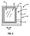
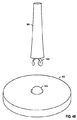
ケース100は、ベース106、支持部材108及びホルダ110を有することができる。支持部材108とホルダ110は、回転可能なコネクタ112で互いに取り付けることができる。図示の実施形態において、ベース106は、床又はテーブル頂面等の平らな又はおおむね平らな作業面上に載置することができるプラットフォーム114を有する。ベース106は、その前方端部に順次連続する一連の溝116を画定することができる。支持部材108は、プラットフォーム114に固着した支柱118を有することができる。例えば、支柱118とプラットフォーム114は単独材料一体ピース(例えば、プラスチック)から一体成形する、又は他の任意な好適方法で互いに固着することができる。そのため、ここに示す支柱118はプラットフォーム114に対して回転可能ではない場合がある。
The
回転可能なコネクタ112又は回転機構は、支柱118の上側端部に配置することができる。コネクタは、ボール−ソケット継手120とし、相互に直交する3つの軸線の周りで回転可能にすることができる。特に明記しない限り、ボール−ソケット継手120は、ホルダ110を、支柱118が規定する軸線の周りに回転する(双頭矢印122で示すように)ことを可能にし、また更に、ホルダ110を、支柱118が規定する軸線に対して互いに直交する、2つの軸線の周りにそれぞれ回転する(双頭矢印122及び124が示すように)ことも可能にする。
A
ホルダ110はPED102を把持する又は固定するよう構成することができる。特定の実施形態において、ホルダ110は、ポケット又はポーチと称される場合もあるスリーブ128を有し、このスリーブ内にPED102を保持するよう構成することができる。例えば、スリーブ128は選択的に伸張できる弾性材料により構成し、前面開口部からPED102を収容し、またPED102の外側端縁の周りに弾性密着できるようにする。ホルダ110及び/又はスリーブ128は、PED102の背面のほぼ全体をカバーするよう構成することもできる。いくつかの実施形態においては、ホルダ110及び/又はスリーブ128はラバー又は他のエラストラマー材料(例えば、シリコーン)で構成し、PED102の周縁の周りに確実な摩擦嵌合を生じてホルダ110及び/又はスリーブ128をPED102の周りに固定することができる。ホルダ110及び/又はスリーブ128は、さらに剛性材料(例えば、プラスチック、金属等)で構成し、また堅固なフレームを設けることができる。若干の実施形態において、ホルダ110及び/又はスリーブ128は、取り外し可能なクリップ、ストラップ、又はPED102を、選択的にホルダ110に固定し、また選択的にホルダ110から釈放できるようにする他のロック構成部を設けることができる。
The
図1〜3は、ディスプレイ104を横向き表示モードに指向させているとき、ユーザーにとってPED102を見易くすることができる、縦長表示にあるケース100を示す。ホルダ110は、PED102のピッチを調節するよう、(矢印124で示すように)1つの軸線の周りを回転させることができる。従って、ホルダ110の底端縁は、任意の溝116に配置することができる。溝116はほぼ直線形にし、これにより、図2に示すように、ホルダ110の底端縁を1つの溝116に配置しているときに、別の軸線周りでの回転(矢印122で示す)を制限することができる。
1-3 illustrate a
図3〜4に示すように、ホルダ110は、別の方向に回転し(矢印122で示す)、ケース100を縦長表示から横長表示に向きを移行できるようにする。図示の実施形態において、ボール−ソケット継手120は、ホルダ110の幅に対する中心から外して配置し、またホルダ110の高さに対して中心に配置し(「幅」及び「高さ」は横長表示の向きに関する)、ホルダ110のボール−ソケット継手120における下側部分の高さは、ホルダ110が縦長表示及び横長表示のいずれの向きにあっても、同一又はほぼ同一になるようにすることができる。結果として、ホルダ110の底端縁は、いずれの向きにおいても、任意の溝116で同様にうまく着座することができる。このような構成において、ホルダ110は縦長表示の向きにあるときベース106に対して中心から外れ、また横長表示の向きにあるときベース106に対して中心に位置する。
As shown in FIGS. 3 to 4, the
他の実施形態において、ボール−ソケット継手120はホルダ110の幅及び高さ双方に対して、中心に配置することができる。支持部材108はベース106に対して固着する場合、PED102を縦長表示及び横長表示の向きにあるとき、ホルダ110の底端縁と溝116との間に異なる相互作用を生ずる結果となる。例えば、若干の溝116は1つの向きでは利用できるが、別の向きでは利用できない場合がある。いくつかの実施形態において、コネクタ112は、ボール−ソケット継手120の他にスライド130又は他の好適な特徴構成部を設け、ホルダ110を中心に配置できるようにする。
In other embodiments, the ball-and-
図1〜4に示した実施形態につき特別に記載した以外の他の構成も、本発明は意図している。例えば、若干の実施形態において、ベース106は、外側端縁相互間が中実であるプラットフォーム114を設けない場合がある。別の又は他の実施形態において、支持部材108は、支柱118よりも幅が相当広いものとすることができる。他の又は別の実施形態において、ホルダ110内にPED102を固定しないが、PED102をホルダ110上に載置する場合がある。さらに、PED102をホルダ110に固定する実施形態では、任意の好適なコネクタ、ストラップ、ホルダ又は他のデバイスを使用して、PED102をホルダ110に固定することができる。いくつかの実施形態において、ホルダ110はPED110のディスプレイ104をカバーする透明保護シート(例えば、プラスチックシート)を設ける場合がある。ホルダ110は、PED102をホルダ110内に導入することができる開口部を、側端縁又は頂端縁に設けることができる。さらに、別の又は他の実施形態において、回転可能なコネクタ112はボール−ソケット継手120ではなく、その代りに互いに直交する少なくとも2つの軸線周りの回転を可能にする他の適切な連結システムを有する構成にすることができる。いくつかの実施形態において、ボール−ソケット継手120は自己張力付与構成とすることができ、また他の実施形態において溝116を使用しない。溝116を使用しない実施形態において、ホルダ110の底端縁は、代替的な適当なコネクタ、例えば、ストラップ、スナップ、フック−ループ式ファスナ等を使用してベース106に固定することができる。
Other configurations other than those specifically described for the embodiment shown in FIGS. 1-4 are also contemplated by the present invention. For example, in some embodiments, the
図5〜10は、PED102を見易くするために使用することができるPED102用の別のケース200を示す。特定の実施形態において、ケース200は図1〜4に示すケース100に似た特徴を有する場合がある。従って、類似特徴部分は、全てではないが、場合によっては、同様の参照符号を付す。同様であると認識される特徴に関する、前記の関連する開示もまた、以降繰り返さない。さらに、図1〜4に示すケース100の具体的な特徴は、図面における参照符号で示さない又は特定せず、以下の記載で特に説明しない場合がある。しかし、このような特徴は、他の実施形態において描かれる及び/又はそのような実施形態に関連して説明される特徴と明らかに同一又はほぼ同一であってよい。したがって、そのような特徴の関連する説明はケース200の特徴に等しく当てはまる。ケース100に関する特徴及び改変のいかなる好適な組合せも、ケース200について使用することができ、逆もまた同様である。この開示のパターンは、後に続く図面に示し、今後説明する、他の実施形態に同様に当てはまる。
5-10 illustrate another
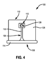
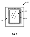
図5に示すように、ケース200は、所定形態においてプラットフォームとして機能する場合があるディスプレイカバー204を含むベース202を有する。ケース200は、さらにヒンジ208でディスプレイカバー204に取り付ける支柱206を設ける。双頭矢印212で示すように、ヒンジ208は、ベース202に対して、ホルダ210を見る位置の調整で1つ以上の自由度を与えることができる。このことは、さらに、図7及び図8に示すように、縦長表示又は横長表示のいずれかの向きで、ホルダ210を中心配置し易くすることができる。ホルダ210は、また、支柱206に着脱可能に取り付け、所望に応じてホルダ210の分離を可能にする。
As shown in FIG. 5, the
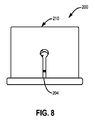
特定の実施形態において、ケース200は図5〜7(すなわち開いた、縦長表示)及び図8(すなわち開いた、横長表示)に示すように、さまざまな開度状態と、図9〜10に示すような閉じた状態との間で移行することができる。図示の実施形態において、ケース200を閉じるとき横長表示の向きとする。ケース200を閉じるとき、ホルダ210はPED102の周面及び背面を包み込み、ディスプレイカバー204は、ディスプレイ104を有するPED102の前面をカバーすることができる。支柱206は曲げて、ホルダ210およびディスプレイカバー204を整列し易くすることができる。
In certain embodiments, the
図11〜12は、PED102を見易くするのに使用できるPED102用の別のケース300を示す。特定の実施形態において、ケース300は開口部304を画定するプラットフォーム302を設けることができる。いくつかの実施形態において、開口部304は横長表示又は縦長表示のいずれの向きであっても、ホルダ306の中に下側端縁を収容するのに十分な大きさにする。ホルダ306は、支持壁308及び1個又はそれ以上のコネクタ310、例えばPED102を支持壁308に押し付けるよう構成することができる弾性ストラップを設けることができる。
FIGS. 11-12 show another
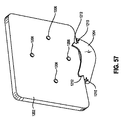
図13〜14は、PED102を見易くするのに使用することができるPED102用の別のケース400を示す。特定の実施形態において、ケース400は2本の支持脚を画定するプラットフォーム402、及びホルダ408を有するものとする。ホルダ408は、支持壁410と、支持壁410から突出する2つ又はそれ以上のレスト412,414を有することができる。PED102は、ホルダ408を縦長表示の向きで見る形態にしたときには支持壁410及びレスト412に立て掛け、またホルダ408を横長表示の向きで見る形態にしたときに支持壁410及びレスト414に立て掛けることができる。いくつかの実施形態において、PED102はホルダ408に物理的に固定しない場合がある。
FIGS. 13-14 illustrate another
図15〜16は、PED102の他に、備品を収納するよう構成したケース500を示す。ケース500は、上述したホルダのようなホルダ502を設けることができる。ホルダ502は、背面カバー504と、上述したコネクタのようなコネクタ506を1つ以上有する構成にすることができる。PED102を背面カバー504に固定する他の方法及び装置も可能であり、本発明の他の実施形態に関して述べるものも含むことができる。背面カバー504はPED102の後面の少なくとも一部をカバーすることができる。
15 to 16 show a
いくつかの実施形態において、背面カバー504はアクセサリを1つ以上保管するよう構成することができる収納領域506を設けることができる。例えば、収納領域506には収納区画508を1つ以上設け、これら区画内にアクセサリを1つ以上収容することができる。これらアクセサリは、イヤホン510、クリーニングクロス512、クリーニング液520、コード(例えば、電源コード)、スタイラスペン等のPED102に関連するものであってよい。図15に示す以外のより多くの又は少ない収納区画508を使用することができ、また区画508は、より大きい又は小さい寸法とすることができる。さらに、例えば弾性ストラップを含む、他の機械的連結機構を使用して、1個又はそれ以上のアクセサリを背面カバー504に固定することができる。
In some embodiments, the
図15〜16に示すように、収納区画508は箱形にし、容器として機能させることができる。収納区画508は、ヒンジ連結した又は取り外し可能なカバーを設け、中身にアクセスし易くすることができる。図示の収納区画508は、PED102の厚さと同一又はそれより僅かに大きい深さにすることができる。したがって、図示の実施形態において、ケース500を閉じたときに、前面カバー514が背面カバー504に対してほぼ平行な向きになることができる。他の実施形態において、1つ以上の収納区画508がスリーブ又はポーチのような形状にすることができる。スリーブは、スナップ、ボタン、フック−ループ式ファスナ等によって封止可能にすることができる。さらに他の実施形態において、1つ以上の収納区画508は、筆記具(例えば、ペン、鉛筆、スタイラスペン)収容するのに特に好適な、ループ又は細長いスリーブとして形成する。
As shown in FIGS. 15 to 16, the
前面カバー514は、任意の適当な方法、例えば1つ以上のヒンジ516、518を介して、背面カバー504に連結することができる。図示の実施形態においては、2つのヒンジ516,518を設ける。第1ヒンジ518は、収納領域506のベースに隣接して配置することができ、第2ヒンジ516は、ケース500を閉じたときに、第2ヒンジ516が収納領域506の上面に隣接するように第1ヒンジ518から距離をあけて配置することができる。このような構成は、前面及び背面のカバー514,504を互いに平行となるよう整列させるのに役立つ。他の実施形態において、収納領域506の上面に配置することができる単一のヒンジを代わりに使用することができる。
The
図15〜16に示す実施形態につき上述した以外の他の構成も意図している。例えば、いくつかの実施形態において、収納領域506を前面カバー514に配置する、又は収納領域の部分を前面及び背面のカバー514,504にそれぞれに配置する。いくつかの実施形態において、収納領域506は1つ以上のカバー504,514の外側端縁に配置することができ、さらに他の又はさらなる実施形態においては、収納領域506は1つ以上のカバー504,514における頂部及び/又は底部の端縁に沿って配置することができる。
Other configurations than those described above for the embodiments shown in FIGS. 15-16 are also contemplated. For example, in some embodiments, the
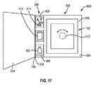
図17は、開いた位置の形態にしたPED102のための回転可能なケース600を示す。特定の実施形態において、回転可能なケース600は、図15〜16に示すケース500及び/又は本明細書に記載するすべてのケースと同様の特徴及び/又はホルダで説明する、さまざまな特徴並びに実施形態の組合せを設けることができる。
FIG. 17 shows a
特定の実施形態において、回転可能なケース600は、PED102をホルダ502、背面カバー504及び/又はPED102の可変回転を可能にする別のPED固定機構を介して回転可能なケース600に取り付ける、回転機構602を設けることができる。例えば、図17に示すように、回転機構602は、PED102をホルダ502、背表紙504に及び/又は回転可能なケース600に対するPED102の可変回転を可能にする別のPED固定機構を介して取り付ける、回転グロメットを有することができる。その他の実施形態において、回転機構602には、ラチェット式のスイベル若しくはピボット、ボール−ソケット機構、一時的接着剤、釈放可能なラッチ、クリップ、1つ以上のボタン、吸着カップ、及び/又は回転固定を可能にする、1つ又はそれより多くのストラップを設けることができる。特定の実施形態において、回転機構602は、特定の回転方向の向き(例えば、縦長表示及び/又は横長表示の向き)にスナップ止めすることができ、また異なる特定の向きに移行させるための回転力を要する場合がある。他の実施形態において、回転機構602は特定の向きにスナップ止めすることができないが、任意な個数の向きに関節的な回動を可能にする。
In certain embodiments, the
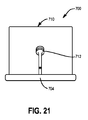
図18〜21は、PED102を見易くするのに使用することができる、PED102用の別のケース700を示す。特定の実施形態において、ケース700は図1〜4に示すケース100、図5〜10に示すケース200と同様の特徴、及び/又は本明細書に記載するすべてのケース及び/又はホルダにつき説明するさまざまな特徴及び実施形態のいかなる組合せを設けることができる。
18-21 show another
図18に示すように、ケース700は、特定形態でプラットフォームとして機能することができるディスプレイカバー704を有する、ベース702を設けることができる。ケース700は、さらに、ヒンジ708でディスプレイカバー704に取り付けた支柱706を設けることができる。ヒンジ708は、ホルダ710を見る位置の調整に関して、ベース702に自由度を1つ以上付与することができる。このことは、図20及び図21にそれぞれ示すように、縦長表示又は横長表示のいずれの向きでも、ホルダ710を中心配置し易くする。
As shown in FIG. 18, the
特定の実施形態において、ケース700は支柱706に対するPED102及び/ホルダ710の1つ以上の方向への可変回転を可能にする、PED102及び/又はホルダ710を、支柱706に取り付ける回転グロメット712を設けることができる。特定の実施形態において、回転グロメット712は特定の回転方向の向き(例えば、縦長表示及び/又は横長表示の向き)にスナップ止めすることができ、また異なる特定方向に移行するための回転力を要する。他の実施形態において、回転グロメット712は特定向きにスナップ止めすることができないが、任意な個数の向きに関節的な回動を可能にする。
In certain embodiments, the
図22は、横長表示の向きにした回転可能なケース800を示す。図示のように、回転可能なケース800は、PED(図示せず)を固定するように構成した固定パネル802を有する。さまざまな実施形態によれば、回転可能なケース800には、ケース800内に配置したPEDを、でコネクタプラグ、ケーブル、ヘッドホン、スピーカー及び/又は電源アダプタに接続し易くする、さまざまなアクセスポート(804及び806等)を設けることができる。特定の実施形態において、回転可能なケース800は、給電、接続性、及び/又はヘッドホンケーブルをPEDから外部機器に経路付けするためのコードを内蔵することができる。さらに、さまざまな実施形態によれば、回転可能なケース800のパネル又はポケットにバッテリを組み込むことができる。
FIG. 22 shows a
特定の実施形態において、回転可能なケース800は、支持パネル808及びベースパネル810に対して固定パネル802を回転させる機能を持たせることができる。さまざまな回転可能な固定装置のうちのいずれかを使用して、固定パネル802を支持パネル808に回転自在に固定することができる。例えば、ブッシング、フランジ付のブッシング、グロメット、リベット、アイレット、滑り軸受、軸受及び/又はそれらの任意な組合せを使用して、固定パネル802を支持パネル808に回転自在に固定することができる。例えば、図示のように、グロメット812は、固定パネル802を支持パネル808に回転自在に固定するよう構成することができる。いくつかの実施形態において、グロメット812は、グロメット812の中心の穴からロゴを見せることができるリングを設けることができる。特定の実施形態において、1つ以上の交換可能なアクセサリ及び/又はインサートを、グロメット812の中心の穴に「スナップ」嵌合することができ、例えば、ロゴインサート、近接アラーム、又は他の紛失防止アクセサリ等を嵌合する。代案として、グロメット812の中心の穴は、回転可能なケース800の内部及び/又は、その中に配置したPED(図示せず)の一部(例えば、ロゴを含むPEDの一部)を見ることができるようにする開口及び/又は開孔を画定することができる。
In certain embodiments, the
ベースパネル810は、固定パネル802を直立した及び/又は上昇した位置にあるとき、固定パネル802の底端縁を固定する、チャネル又は溝814を有する構成とする。さまざまな他の実施形態によれば、溝814の位置に摩擦面(例えば、ゴム引きの表面等)又は摩擦接触パッチを利用して、固定パネル802の底端縁を直立した及び/又は上昇した位置に固定することができる。
The
支持パネル808は、固定パネル802に対する対向力を与えて、固定パネル802を直立した及び/又は上昇した位置に支持できるよう構成することができる。図示のように、支持パネル808及びベースパネル810は、部分816で折り曲げた又は湾曲した単独パネルにより構成することができる。さまざまな実施形態によれば、ベースパネル810及び支持パネル808の相対的プロポーションは、特定用途に適合させることができる。さらに、ある実施形態において、回転可能なケース800は、ベースパネル810に対する1つ以上の角度でPEDを支持し、また縦長表示及び横長表示の向きを含む複数の向きにして支持する構成にすることができる。
The support panel 808 can be configured to provide an opposing force to the fixed
図23は、縦長表示の向きに回転させたPED102用の回転可能なケース800を示す。図1に示す実施形態と同様に、ベースパネル810には、PED102の底端縁及び/又は固定パネル802の底端縁を固定するよう構成した1つ以上の隆起部又は溝814を設けることができる。回転可能なケースには、さらに部分816でベースパネル810に対して折り畳めるよう構成した支持パネル808を設けることができる。
FIG. 23 shows a
図22及び図23の比較は、本明細書に記載する上述の実施形態と同様に、支持パネル808に対して、固定パネル802を回転させる機能を示す。さまざまな実施形態によれば、グロメット812は、PED102を図22に示す横長表示の向きから図23に示す縦長表示の向きに回転させることができる。
Comparison of FIG. 22 and FIG. 23 shows the function of rotating the fixed
特定の実施形態において、固定パネル802、ベースパネル810及び/又は支持パネル808は包囲したPED102を保護することができる。例えば、固定パネル802、ベースパネル810及び/又は支持パネル808は引っ掻き傷、落下によるダメージ、極端な温度及び/又はPED102へのダメージを与える他の条件から保護するよう構成することができる。したがって、回転可能なケース800のあらゆる部分も、詰め物、金属、プラスチック、段ボール、ゴム及び/又は他の材料若しくはその組合せによって補強することができる。
In certain embodiments, the fixed
特定の実施形態において、補強材は、望ましい耐性及び/又は弾性を得るために、さまざまな折り畳み部、曲げ部及び/又は湾曲部を使用することができる。例えば、折り畳み部816は、ユーザーが支持パネル808をベースパネル810に対して、1つ以上の既定の角度に選択的に折りたたむことを可能にする二安定の、三安定の、N回安定の折り畳み部として機能するよう構成することができる。いくつかの実施形態においては、N回安定の折り畳み部816を設けることで、1箇所以上の所定位置に支持パネル808を効果的に「スナップ」嵌合し、ベースパネル810に対して所定角度でPED102を支持することができる。
In certain embodiments, the reinforcement may use various folds, bends and / or curves to obtain the desired resistance and / or elasticity. For example, the
図24は、PED102をその内部に固定するよう閉じた状態にした、回転可能なケース800を示す。図示のように、固定パネル802にはアクセスポート804を1つ以上設けることができる。グロメット812は、支持パネル808を固定パネル802に回転自在に固定するよう作用することができる。特定の実施形態において、グロメット812には、回転可能なケース802が閉じた位置にあるときにも、PED102の一部が見えるようにするシースルーの中心サークルを設けることができる。いくつかの実施形態において、透明材料により、グロメット812が形成するサークルの中心をカバーすることができる。他の実施形態によると、グロメット812の中心サークルを、支持パネル808及び/又は固定パネル802に使用したのと同一タイプの材料を含む、任意なタイプの材料で充填することができる。
FIG. 24 shows the
支持パネル808は、下側部分818及びピボットフラップ820を有する構成にすることができる。ピボットフラップ820は、支持パネル808の下側部分818に対して折れ曲がる又は回動するよう構成することができる。図示のように、グロメット812をピボットフラップ820に固定し、グロメット812及び固定パネル802が、支持パネル808の下側部分818に対して回動できるようにすることができる。
The support panel 808 can be configured with a
さまざまなファスナ(図示せず)のいずれかを使用して、回転可能なケース800を選択的に閉じた位置に維持することができる。例えば、ファスナは、固定パネル802をベースパネル810に対して平行となる状態に選択的に維持するよう構成することができる。ファスナは、ケース、バッグ、旅行かばんに一般的に使用されるさまざまなファスナのうち任意なものとすることができる。あり得る閉止機構の例としては、以下に限定しないが、ストラップ、ボタン、フラップ、スナップ、ベルクロ(登録商標)、フック、クラスプ、マグネット及びこれらの組合せがある。特定の実施形態において、弾性ストラップの端部を、ベースパネル810に固定し、またそのストラップを固定パネル802の周りに選択的に巻き付けることができる。したがって、固定パネル802は閉じた位置に弾性的に維持することができる。さらに、図示しないが、回転可能なケース800には、この回転可能なケース800をユーザーが容易に持ち運べるよう構成した、さまざまなストラップ、ハンドル、ハーネス及び/又は同等物のうちいずれかを設けることができる。
Any of a variety of fasteners (not shown) can be used to maintain the
図25は、PED102を横長表示の向き及び第1開度位置に固定する回転可能なケース800を示す。図示のように、支持パネル808は、ベースパネル810に対して、部分816で折り曲げることができる。グロメット812は、支持パネル808に対して、固定パネル802を回転自在に固定するよう構成することができる。特定の実施形態において、グロメット812は、支持パネル808のピボットフラップ820を固定パネル802に回転自在に固定し、これによって、固定パネル802が支持パネル808の下側部分818に対して回動できるようになる。いくつかの実施形態において、グロメット812は、中心リングからPED102の一部を見ることができるようにする。例えば、PED102に設けたロゴを見ることができるようにする。
FIG. 25 shows a
上述のように、ベースパネル810には、固定パネル802の底部端縁が直立した及び/又は上昇した支持位置にあるとき、スリップするのを防止するよう構成した、溝814を1つ以上設けることができる。1つ以上の溝814の代わりとしての代替的な造作部、例えば、隆起部、摩擦接触パッチ、キャッチ、マグネット、突起部及び/又は固定パネル802の底端縁がスリップすることを防止するよう構成した他の造作部を使用することができる。特定の実施形態において、固定パネル802には、ヘッドホンアクセスポート804等のアクセスポートを1つ以上設けることができる。
As described above, the
図26は、横長表示の向き及び第2開度位置における角度でPED(図示せず)を支持する回転可能なケース800を示す。とくに、図26は、回転可能なケース800に設けたピボットフラップ820(この図では見えていない)の機能を示す。上述のように、ピボットフラップ820を支持パネル808の下側部分818に対して折り曲げることで、固定パネル802を支持パネル808に対して回動させることができる。図示の位置では、支持パネル808は、ベースパネル810に対する角度で固定パネル802を支持する。溝814のうち、第1溝が固定パネル802の底端縁がベースパネル810に沿ってスリップするのを防ぐ。特定の実施形態において、部分816におけるピボットフラップ820及び/又は支持パネル808のさらなる折り畳み度合いにより、固定パネル802の底端縁を溝814のうち別の溝に配置することで、さまざまな傾斜角で支持することを可能にする。特定の実施形態において、固定パネル802はヘッドホンアクセスポート804等のアクセスポートを1つ以上設けることができる。
FIG. 26 shows a
図27は、PED102を所望の傾斜角位置に回動できるよう構成したピボットフラップ820(この図では見えていない)を含む回転可能なケース800によって固定したPED102を示す。ピボットフラップ820(この図では見えていない)は、PED102を支持パネル808に対して回動するよう、固定パネル802内に固定できる。図示のように、PED102は所望の傾斜角位置に回動させることができる。特定の実施形態において、PED102は、PED102がベースパネル810に対して平行な状態にある、図24に示す閉じた位置からベースパネル810に対する任意の傾斜角位置にも回動させることができる。したがって、PED102は、固定パネル802が再度ベースパネル810に対して平行になり、PED102のディスプレイ104が上向きの状態になるまで回動させることができる。
FIG. 27 shows the
特定の実施形態において、固定パネル802により固定したPED102は所望傾斜角位置に回動させることができる。支持パネル808は、この所望傾斜角位置にPED102を維持するのに十分な支持を行うことができる。1つ以上の溝814は、固定パネル810の底端縁がベースパネル810に沿ってスリップすることを防ぐことができる。
In certain embodiments, the
図28は、縦長表示の向きから横長表示の向きへ、及びその逆に回転するよう構成したグロメット812(この図では見えていない)を有する回転可能なケース800で固定したPED102を示す。図示のように、回転可能なグロメット812(この図では見えていない)は、固定パネル802に配置したPED102を縦長表示の向きから横長表示の向きへ及びその逆に回転するよう構成できる。特定の実施形態において、PED102は図22に示す第1横長表示位置から、図23に示す第2縦長表示位置に回転するよう構成することができる。特定の実施形態において、PED102は任意の所望向きとなるよう360°回転させることができる。
FIG. 28 shows the
いくつかの実施形態において、PED102は特定向きにのみ回転するよう構成することができる。例えば、0°では、PED102は第1横長表示の向きをとり、PED102は、第1縦長表示の向きに90°、第2横長表示の向きへさらに90°、第2縦長表示の向きへ、最後の90°回転させることができる。第2縦長表示の向きで止め部に達し、PED102を先の向きに戻すには反対方向へ回転させることができる。特定の実施形態において、ケース800の回転機構(例えば、グロメット812)は、特定向きにスナップ嵌合することができ、異なる特定向きに回転するには回転力が必要となるようにする。
In some embodiments, the
図29は、PED102を縦長表示の向きに固定する回転可能なケース800の背面図を示す。図示のように、ピボットフラップ820は、支持パネル808の下側部分818に対して折り曲げることができる。したがって、固定パネル802で固定したPED102は、支持パネル808及びベースパネル810(この図では見えていない)に対して、1つ以上の特定角度で支持することができる。グロメット812又は他の回転機構は、固定パネル802をピボットフラップ820に回転自在に固定することができる。上述のように、グロメット812はPED102及び固定パネル802を支持パネル808に対して回転させることができ、このことは、例えば、縦長表示及び/又は横長表示の向きを含む。
FIG. 29 shows a rear view of a
図30は、グロメット812を介した、回転可能なケース800の支持パネル808と固定パネル802との間における相互作用を示す。特定の実施形態において、グロメット812は後方部分812及び前方部分822を有する。回転可能なケース800は、溝814を1つ以上有するベースパネル810、下側部分818を有する支持パネル808及びピボットフラップ820及びグロメットの後方部分812を有することができる。アクセスポート804を1つ以上有する固定パネル802は、グロメットの前方部分822に取り付けることができる。さまざまな実施形態によれば、固定パネル802を回転自在にピボットフラップ820に固定するために、グロメットの前方部分822はグロメットの後方部分812に合体させて固定パネルをピボットフラップ820に回転可能に固定することができる。このようにして、固定パネル802は、自由に支持パネル808の周りで360°回転させることができる。
FIG. 30 shows the interaction between the support panel 808 and the fixed
特定の実施形態において、グロメットの前方部分822及びグロメットの後方部分812は、製造又は組立中で互いに結合することができ、ユーザーが選択的に分解できるよう構成しない。代案として、ユーザーはピボットフラップ820から固定パネル802を取り外すよう、グロメットの後方部812から前方部分822を選択的に分離できるようにする。他の実施形態において、グロメットの前方部分822及び後方部分812を分離不能にし、グロメットは、ピボットフラップ820及び/又は固定パネル102から選択的に取り外し可能にすることができる。
In certain embodiments, the grommet front portion 822 and the grommet
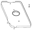
図31は、回転可能なケース800の固定パネル802及びグロメット822の前方部分を示す。固定パネル802は、PED102(図示せず)の端縁を保護及び/又は固定する側壁を有することができる。さまざまな実施形態によれば、PED102は、固定パネル802内の所定位置にスナップ嵌合することができる。代案として、PED102は、1つ以上のストラップ、バックル、クリップ、接着剤及び/又は類似する造形部を使用し、固定パネル802に固定することができる。固定パネル802には、さらに、PED102を選択的に固定するためにネオプレン又は天然ゴムを利用することができる。さらに、固定パネル802の側壁又は側壁の一部を、固定したPED102の前部を包むようにすることができる。特定の実施形態において、固定パネル802は、本明細書に記載するホルダに類似のホルダを設けることができる。
FIG. 31 shows the fixed
固定パネル802には、さらに1つ以上のアクセスポート804、806、824を設けることができる。例えば、ヘッドホン用アクセスポート804、ボリュームロッカー用アクセスポート806及び/又は電源若しくは接続用アクセスポート824を利用可能にする。上述のように、グロメット部分822は、固定パネル802を支持パネル808のピボットフラップ820に回転自在に固定するよう構成することができる。固定パネル802は、プラスチック、天然ゴム、金属、皮革、人工皮革、ビニール、ナイロン及び/又はケース、バッグ、旅行かばん等に利用される、さまざまな代替的装飾用若しくは有用な材料のうちいずれかで構成することができる。
The fixed
図32は、ピボットフラップ820及びグロメット812を有する回転可能なケース800の支持パネル808を示す。図示のように、ピボットフラップ820は、グロメット812を有し、支持パネル808の下側部分818に対して折り曲げるよう構成できる。したがって、ピボットフラップ820及びグロメット812は、支持パネル808の下側部分818に対して、所望の傾斜角位置に回動することができる。さまざまな実施形態によると、ピボットフラップ820は、回動力を取り除いたとき、弾性的に、元の、折り曲げていない位置に戻るよう構成できる。代案として、ピボットフラップ820は、支持パネル808の下側部分818に対して回動し、またその後に新たな傾斜角位置に移行させられるまで、その位置を維持するよう構成することができる。
FIG. 32 shows a support panel 808 of a
ピボットフラップ820は、さまざまな既知の回動可能なコネクタのいずれかを利用して支持パネル808の下側部分818に連結することができる。いくつかの実施形態において、下側部分818及びピボットフラップ820の双方を有する支持パネル808は、皮革、人工皮革及び/又はビニール等の材料又は生地を使用して製造することができる。このような実施形態において、ピボットフラップ820と支持パネル808の下側部分818との間における回動可能な連結部は、類似の又は同一の材料による縫合部とすることができる。
The
図33は、より大きなケース826に組み込んだ回転可能なケース800を示す。図示のように、回転可能なケース800は、より大きなケース826の追加のサイドポケットとして組み込むことができる。さまざまな実施形態によれば、回転可能なケース800は、代案として、より大きなケース826の内部区画内に組み込むことができる。さらに、特定の実施形態において、ベースパネル810は、より大きなケース826の共用のパネル又は壁面とすることができ、また、したがって、回転可能なケース800の残りの部分のみを設けるようにする。つまり、より大きなケース826は、回転可能なケース800のベースパネル810と共通の壁面を共有することができる。
FIG. 33 shows a
特定の実施形態において、回転可能なケース800は、本明細書に記載するケースのいずれかにつき説明する、さまざまな特徴部及び実施形態のいかなる組合せをも設けることができる。さらに、より大きなケース826は、ハンドル830およびファスナ828を有する構成にすることができる。より大きなケース826は、ブリーフケース、旅行かばん、ノート型パソコンケース、PED102用のケース等を含むさまざまなケースのいずれであってもよい。
In certain embodiments, the
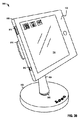
図34は、ベース902、垂直支持体904及び横長表示の向きにしたケース906を含むPED(図示せず)用のマルチピボット式のスタンド900を示す。特定の実施形態において、ベース902は、ケース906内に固定したPEDを適切に支持できる、任意の形状及び/又はサイズで構成することができる。いくつかの実施形態において、ベース902は重りを付加し、調整可能な脚を設け、滑り止め加工した底面及び又は頂面を有する、及び/又はそれらに配置したロゴを設けることができる。
FIG. 34 shows a
垂直支持体904は、下側連結部材908を介してベース902に結合することができる。特定の実施形態において、下側連結部材908は、垂直支持体904を、ベース902に対してさまざまな角度及び向きに回転および回動できるよう構成したスイベル継手を有する構成とすることができる。いくつかの実施形態において、下側連結部材908は、垂直支持体904を回転できるが回動できない、又は回動できるが回転できない、又は回転も回動もできるよう構成したスイベル継手を有する構成にすることができる。下側連結部材は、さらに、玉継手、ボール−ソケット連結部、軸受、ピボットロッド、スリップリング、スイベル継手、スイング継手等を含む、さまざまな従既知の回転可能な及び/又は回動可能な連結部により構成することができる。
The
特定の実施形態において、下側連結部材908は、ベース902に対して垂直支持体904を固定する、固定連結部材を有する構成とすることができる。垂直支持体904及びベース902は、さらに、単独ピースとして製造することもでき、これによって、垂直支持体904とベース902との間の相対運動を制限する。
In certain embodiments, the
ケース906は、PED(図示せず)を固定するよう構成することができる。特定の実施形態において、ケース906は、本明細書に記載する他のケース及びホルダに類似のコンポーネント及びデザインで構成することができる。アクセスポート910〜914の寸法及び位置を含めた、ケース906のデザインは、特定のPEDに適合させることができる。いくつかの実施形態において、PEDは、1つ以上のコーナー固定部材(例えば、弾性ストラップ)を使用して、ケース906内にスナップ嵌合させる又は固定するよう構成することができる。特定の実施形態において、ケース906は、PEDを固定するよう構成した可撓性側壁を設けることができる。いくつかの実施形態において、可撓性側壁は、PEDの側面及び/又は前面の一部に巻き付けることで、PEDを固定するよう構成することができる。
以下に詳しく説明するように、ケース906は、ケース906を垂直支持体904に対して回転及び/又は回動できるよう構成した上側連結部材(この図では見えていない)を介して、垂直支持体904に結合することができる。特定の実施形態において、スタンド900には、下側連結部材908及び/又は上側連結部材を選択的にロック及び釈放するよう構成したレバー916を設けることができる。スタンド900には、さらに、例えば1つ以上の連結部材を個別に操作するよう構成した複数のレバーを設けることができる。
As will be described in detail below, the
図35は、データドック918を含むPED(図示せず)用のマルチピボット式のスタンド900を示す。特定の実施形態において、データドック918は、ケース906で固定したPEDへの給電及び/又はデータ接続を行うよう構成することができる。さまざまな実施形態において、データドック918は、例えば、ケーブル922を介したUSBコネクタ及び/又は電源コネクタなどの外部コネクタ920に通信可能に接続できる。いくつかの実施形態において、データドック918のタイプ、形状、サイズ及び個数は、特定のPEDに適合させることができる。特定の実施形態において、データドック918及び外部コネクタ920は、互いに及び/又はさまざまな代替コネクタと互換性があるものとすることができる。
FIG. 35 shows a
図36は、横表示にしたPED102を固定したマルチピボット式のスタンド900を示す。図示のように、スタンド900のケース906の部分は、その内部にPED102を固定するよう構成することができる。いくつかの実施形態において、PED102は、1つ以上のコーナー固定部材(例えば、弾性ストラップ)を使用して、ケース906にはめ込むよう構成することができる。特定の実施形態において、ケース906は、PED906を固定するよう構成した可撓性側壁を有する構成とすることができる。いくつかの実施形態において、可撓性側壁は、PED906の側面及び/又は前面の一部に巻き付けるとともに、依然としてユーザーがディスプレイ104を見ることができる状態で、PED906を固定するよう構成することができる。
FIG. 36 shows a
図37は、マルチピボット式のスタンド900の背面図を示す。図示のように、スタンド900は、上側連結部材926を介して、垂直支持体904に結合したケース906を有する構成とする。さらに、垂直支持体904は、垂直支持体904がベース902に対して1つ以上の方向に回転及び/又は回動できるように、下側連結部材908を介してベース902に結合することができる。特定の実施形態において、上側連結部材926は、ケース906が、垂直支持体904に対して1つ以上の方向に回転及び回動できるようにするボール−ソケット型の連結部とすることができる。特定の実施形態において、上側連結部材926は全般的に回転機構として記載することができる。さまざまな実施形態において、ケースはアクセスポート914(例えば、電源及び/又はデータ用のアクセスポート)を1つ以上設けることができる。
FIG. 37 shows a rear view of the
釈放レバー916は上側連結部材926及び/又は下側連結部材908を選択的にロック及び釈放するよう構成することができる。例えば、ロックしたとき、釈放レバー916は、ケース906が垂直支持体904、ケース906及び/又はベース902に対して、1つ以上の方向へ回動及び/又は回転することを、選択的に阻止するよう構成することができる。特定の実施形態において、釈放レバー916は、とくに、垂直支持体904に対するケース906の垂直及び水平な方向への回動を選択的にロック及び/又は釈放するよう構成することができる。いくつかの実施形態において、ケース906は、釈放レバー916の状態に関係なく、縦長表示の向きから横長表示の向きに回転するよう構成することができる。
ケース906は、マウント部924を介して上側連結部材926に固定することができる。特定の実施形態において、ケース906及び/又は上側連結部材926は、マウント部924から選択的に脱着できるようにする。
The
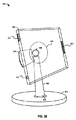
図38は、マルチピボット式のスタンド900の側面図を示す。マルチピボット式のスタンドには、下側連結部材908を介して、ベース902に回動自在に結合した垂直支持体904を設けることができる。特定の実施形態において、下側連結部材908は、垂直支持体904がベース902に対して1つ以上の方向に回転及び/又は回動できるようにする。
FIG. 38 shows a side view of a
PED(図示せず)を固定するよう構成したケース906は、マウント部924を介して上側連結部材926に結合することができる。代案として、ケース906は、上側連結部材926に直接結合することができる。特定の実施形態において、上側連結部材926は、ケース906を垂直支持体904に対して1つ以上の方向に回動及び/又は回転させることができるように、ケース906を垂直支持体904に回転自在に結合するよう構成することができる。釈放レバー916は、上側連結部材926の動きを、選択的にロック及び釈放するよう構成することができる。
A
図39は、垂直支持体904に結合したケース906を有するマルチピボット式のスタンド900を示す。特定の実施形態において、ケース906は、上側連結部材916(点線で示す)を介して、垂直支持体904に結合することができる。いくつかの実施形態において、上側連結部材916は、マウント部924(点線で示す)を介して、ケース906に結合することができる。
FIG. 39 shows a
ケース906は、垂直支持体904に対して1つ以上の方向に回動及び/又は回転するよう構成することができる。垂直支持体904は、下側連結部材908を介してベース902に結合し、またベース902に対して1つ以上の方向に回動及び/又は回転するよう構成することができる。釈放レバー916は、上側連結部材926及び/又は下側連結部材908を、選択的にロック及び釈放するよう構成することができる。
The
特定の実施形態において、上側連結部材926及び/又は下側連結部材908は、PED(図示せず)をケース906内に固定したとき、その位置を摩擦力で維持するよう構成することができる。例えば、特定の実施形態において、上側連結部材926及び下側連結部材908を1つ以上の方向に自由に回転及び/又は回動できる位置に釈放レバー916がセットされていても、摩擦力は、外部の力(例えば、スタンド900の位置を変更するユーザーによる力)が作用するまで、連結部材926,908双方がそれらの位置を維持できるようにする。
In certain embodiments, the upper connecting
図40は、横長表示の向きから縦長表示の向きにケース906を回転させるために、マルチピボット式のスタンド900の上側連結部材(この図では見えていない)を選択的に釈放するように設定した釈放レバー916を示す。図示のように、釈放レバー916は、例えば、ケース906に向けて手前に引き寄せることで作動させることができる。代案として、釈放レバー916は、他方向へ動かすこと、特定方向への回転、レバー916を外方に引っ張ること及び/又はレバー916を内向きに押し込むことでも、作動させることができる。特定の他の実施形態において、釈放レバー916は、釈放ボタン、又は上側連結部材926及び/又は下側連結部材908の構成を、選択的に作動させるよう構成した、他の機械装置とすることができる。
FIG. 40 is set to selectively release the upper connecting member (not visible in this figure) of the
図41は、図40に示すのとは別の状態における釈放レバー916を示す。図示のように、釈放レバーを作動させたとき、ケース906を、縦長表示から横長表示の向きに自由に回転させることができる。特定の実施形態において、釈放レバー916を作動させたとき、複数の向きになるように、1つ以上の方向に回転させることができる。また、ケース906は、1つ以上のプリセットされた向きに対応する1つ以上の位置及び/又は向きに、ロックする(例えば、スナップ機構等を介して)よう構成することができる。
41 shows the
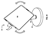
図42は、横長表示の向きから縦長表示の向きに回転可能にPED(図示せず)を固定するよう構成したケース906を含む、別のマルチピボット式のスタンド900を示す。特定の実施形態において、釈放レバー(図示せず)は、ケース906を各向きの相互間で回転させる前に、作動させる必要があるようにする。代案として、ケース906は、釈放レバーとは無関係に自由に回転させることができるようにする。特定の実施形態において、釈放レバーは、選択的に、ケース906が垂直方向及び水平方向に回動することを阻止するが、回転は阻止しないよう構成することができる。いくつかの実施形態において、ケース906は、1つ以上の所望の向き(例えば、90°毎の向き及び/又は縦長/横長表示の向き)にロック(例えば、スナップ嵌合)できるようにする。ケース906に結合した垂直支持体904は、ベース902に対してさらに回転及び/又は回動できるようにする。
FIG. 42 shows another
図43〜44は、上側連結部材(図示せず)の周りを垂直方向に回動するよう構成したケース906を含むマルチピボット式のスタンド900を示す。ベース902は、特定の実施形態において、ベース902に対して1つ以上の方向に回転可能及び/又は回動可能となるよう、垂直支持体904に結合することができる。垂直支持体904は、上側連結部材(図では見えていない)を介して、回転自在に及び/又は回動自在にケース906に結合することができる。釈放レバー916は、上側連結部材を選択的にロック及び釈放し、また垂直支持体904に対するケース906及び/又はベース902に対する垂直支持体904の回転及び/又は回動を制御するよう構成できる。
43-44 illustrate a
図45〜46は、上側連結部材(図示せず)の周りを水平方向に回動するよう構成したケース906を有するマルチピボット式のスタンド900を示す。特定の実施形態において、ベース902に対して1つ以上の方向に回転自在及び/又は回動自在となるよう垂直支持体904に結合することができる。垂直支持体904は、上側連結部材(図では見えていない)を介して、ケース906に回転自在に及び/又は回動自在に結合することができる。垂直支持体904は、さらに、下側連結部材908を介してベース902に回転自在に及び/又は回動自在に結合することができる。釈放レバー916は、上側連結部材及び/又は下側連結部材908を選択的にロック及び釈放し、垂直支持体904に対するケース906及び/又はベース902に対する垂直支持体904の回転/回動を制御するよう構成することができる。上側連結部材及び/又は下側連結部材908を使用して、ケース906を、図示のように、ベース902に対して、水平に回転及び/又は回動させることができる。特定の実施形態において、ケース906を回転及び/又は回動させるには、釈放レバー916が作動していることが必要となるようにする。
45-46 show a
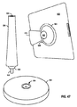
図47は、ベース902、下側連結部材908、垂直支持体904、上側連結部材926及びPEDを固定するよう構成したケース906を有する、マルチピボット式のスタンドにおけるコンポーネントの分解図を示す。スタンドには、さらに、ケース906に結合した釈放レバー916及びマウント部924を設けることができる。
FIG. 47 shows an exploded view of components in a multi-pivot stand having a base 902, a
垂直支持体904は、回転自在に及び/又は回動自在にベース902に結合することができる。特定の実施形態において、下側連結部材908は、垂直支持体904に対して、固定的に又は回転自在に結合した玉継手を有する構成とする。下側連結部材908には、ベース902に配置した下側結合ピン受容部934に収容するよう構成した、下側結合ピン932を設けることができる。特定の実施形態において、下側結合ピン932は、下側結合ピン受容部934によって、圧嵌及び/又は摩擦嵌合を使用して、確実に収容されるようにすることができる。他の実施形態において、下側結合ピン932は、下側結合ピン受容部934によって、下側結合ピン932及び/又は下側結合ピン受容部934に組み込んだねじ付き機構(threaded mechanism)を使用して、収容されるようにすることができる。更なる実施形態において、下側結合ピン932は、下側結合ピン受容部934によって、下側結合ピン932及び/又は下側結合ピン受容部934に組み込んだ、機械的ラッチ機構を使用して、確実に収容されるようにすることができる。
The
垂直支持体904は、ケース906に回転自在に、及び/又は回動自在に結合することができる。特定の実施形態において、上側連結部材926は、特定の実施形態において、マウント部924を介して、固定的に又は回転自在にケース906に結合した玉継手を有する構成とする。特定の実施形態において、ケース906及び/又は上側連結部材926は、マウント部924に対して選択的に脱着できるようにする。
The
上側連結部材926には、垂直支持体904に配置した上側結合ピン受容部930によって収容するよう構成した、上側結合ピン928を設けることができる。特定の実施形態において、上側結合ピン928は、上側結合ピン受容部930によって、圧嵌及び/又は摩擦嵌合を使用して、収容されるようにすることができる。他の実施形態において、上側結合ピン928は、上側連結ピンレセプタ930によって、上側結合ピン928及び/又は上側結合ピン受容部930に組み込んだねじ付き機構(threaded mechanism)を使用して、収容されるようにすることができる。更なる実施形態において、上側結合ピン928は、上側結合ピン受容部930によって、上側結合ピン928及び/又は上側結合ピン受容部930に組み込んだ、機械的ラッチ機構を使用して、確実に収容されるようにすることができる。特定の実施形態において、釈放レバー916は、上側連結部材926及び/又は下側連結部材908を、選択的に、回動自在に及び/又は回転自在にロック及び釈放するよう構成することができる。
The
図48は、ベース902、及び下側連結部材1002、1004を介して回動的に結合するよう構成した垂直支持体904を示す。図示のように、下側連結部材は、ベース902に堅固に結合した底部ボール1004を有する構成とする。垂直支持体904に結合した垂直支持体ボール受容部1002は、機械的に及び/又は摩擦で底部ボール1004を把持するよう構成することができる。特定の実施形態において、垂直支持体904は、釈放レバー等の選択的な釈放及びロック機構に無関係に下側連結部材1002,1004を介して、ベース902に対して回転及び/又は回動することができる。代案として、垂直支持体904は、選択的な釈放及びロック機構の作動に基づく、可変抵抗度で下側連結部材1002,1004を介して、ベース902に対して回転及び/又は回動させることができる。
FIG. 48 shows a
図49は、ベース902と、別の下側連結部材1006,1008を介して、回動的に結合するよう構成した垂直支持体904とを示す。図示のように、下側連結部材は、垂直支持体904に堅固に結合した垂直支持体ボール1006を有する構成とする。ベース902に結合した底部ボール受容部1008は、垂直支持体ボール1006を機械的に及び/又は摩擦で把持するよう構成することができる。特定の実施形態において、垂直支持体904は、釈放レバー等の選択的な釈放及びロック機構に無関係に、下側連結部材1006,1008を介して、ベース902に対して回転及び/又は回動することができる。また、垂直支持体904は、選択的な釈放及びロック機構の作動に基づく、可変抵抗度で下側連結部材1006,1008を介して、ベース902に対して回転及び/又は回動させることができる。
FIG. 49 shows a
図50は、下側連結部材932,934を介して、互いに回動自在に結合するよう構成した、例示的な、ベース1010及び垂直支持体904を示す。図示のように、ベース1010は1つ以上の脚部材を有し、これら脚部材は、ベース1010が位置する表面から突出することができる。垂直支持体904は、回転自在及び/又は回動自在に、ベース1010に結合することができる。特定の実施形態において、下側連結部材908には、垂直支持体904に対して固定的に又は回転自在に結合した玉継手を設けることができる。下側連結部材908は、下側連結部材908に配置し、ベース902に配置した下側結合ピン受容部934で収容するよう構成した、下側結合ピン932を有する構成とすることができる。特定の実施形態において、下側結合ピン932は、下側結合ピン受容部934によって、圧嵌及び/又は摩擦嵌合を使用して、確実に収容されるようにすることができる。他の実施形態において、下側結合ピン932は、下側結合ピン受容部934によって、下側結合ピン932及び/又は下側結合ピン受容部934に組み込んだねじ付き機構(threaded mechanism)を使用して、確実に収容されるようにすることができる。更なる実施形態において、下側結合ピン932は、下側結合ピン受容部934によって、下側結合ピン932及び/又は下側結合ピン受容部934に組み込んだ、機械的ラッチ機構を使用して、確実に収容されるようにすることができる。
FIG. 50 illustrates an
図51〜52は、PED用のホルダ1100を示す。ホルダ1100は、ケース1102、ハンドグリップ1104、及びハンドグリップ1104をケース1102にしっかりと取り付けるよう構成した結合機構1106,1108を有する構成とすることができる。ケース1102は、PEDを収容し、固定し、また持ち運ぶよう構成し、そして本明細書に記載したケースに関する他の実施形態の特徴を組み込むことができる。
51 to 52 show a
ハンドグリップ1104は、ベースプレート1110及びベースプレート1110に結合したストラップ1112を有する構成とすることができる。特定の実施形態において、ユーザーは、体の一部(例えば、手又は前腕)をベースプレート1110とストラップ1112との間に滑り込ませて、ベースプレート1110をユーザーに固定することができるようにする。特定の実施形態において、ストラップ1112は、ベースプレート1110と一体に形成することができる。他の実施形態において、ストラップ1112は、ベースプレート1110の少なくとも一部の周りに挿通及び/又は巻き付けることができる。
The
ストラップ1112の内部及び/又はベースプレート1110は、快適な使用感を与えるよう、少なくとも部分的に、詰め物及び/又は柔らかい材料(例えば、マイクロファイバ)で内張りすることができる。特定の実施形態において、ベースプレート1110は、図示のように、ユーザーの手のひらに心地よく適合するよう、円形形状にすることができる。他の実施例において、ベースプレート1110は、任意の適切な及び/又は人間工学的な形状にすることができる。
The interior of the
結合機構1106,1108は、ハンドグリップ1104のベースプレート1110をケース1102に取り外し自在に固定することができるよう構成する。特定の実施形態において、結合機構1106,1108は、ハンドグリップ1104がケース1102に対して回転自在となるよう、ハンドグリップ1104をケースに結合することができる。図示の実施形態において、結合機構1106,1108は、回転させることができるように、容易に分離させることができるベルクロ(登録商標)等のフック−ループにより構成する。例えば、ループ部分1108は、ケース1102に確実に取り付け、またフック部分1106は、ハンドグリップ1104に確実に取り付けることができる。
The
フック部分1106及びループ部分1108が接触するとき、ハンドグリップ1104はケース1102に固定することができる。ハンドグリップ1104は、フック部分1106及びループ部分1108を分離(すなわち、ハンドグリップ1104をケース1102から分離させることで)させ、所望に応じてハンドグリップ1104を回転させ、フック部分1106とループ部分1108を再結合することで、ケース1102に対して回転させることができる。特定の実施形態において、結合機構1106,1108は、90°よりも少ない角度位置を含む、任意の所望角度にわたり、ケース1102のハンドグリップ1104に対して回転させることを可能にし、それによって、ユーザーが快適なケース1102の回転方向位置を見つけることを可能にする。他の実施形態において、結合機構1106,1108は、選択した向きのみ使用可能となるよう構成することができる。例えば、1つの実施形態において、結合機構1106,1108は、90°間隔でのケース1102の回転方向向きのみ許可するよう構成することができる。
The
ループ部分1108は、接着材でケース1102に取り付けることができる。別の実施形態において、ループ部分1108は、ケース1102に一体に形成することができる。同様に、フック部分1106は、接着剤でハンドグリップ1104のベースプレート1110に取り付ける、又はベースプレート1110に一体に形成することができる。
The loop portion 1108 can be attached to the
結合機構1106,1108は、ケース1102を、ハンドグリップ1104に対して回転させることを可能にする、任意の好適な固定装置とすることができる。例えば、結合機構1106,1108としては、ラチェット式のスイベル若しくはピボット、回転グロメット機構、ボール−ソケット機構、一時的接着剤、釈放可能なラッチ、クリップ、1つ以上のボタン、吸着カップ、及び/又は回転固定を可能にする1つ以上のストラップがある。
The
特定の実施形態において、結合機構1106,1108は、PED(図示せず)に直接結合することができる。例えば、ループ部分1108は、PEDの背面に直接取り付けるよう構成及び配置することができる。PEDの背面に接着するよう設計した接着剤は、ループ部分1108の背面に塗布することができる。他の実施形態において、フック部分1106は、PEDに直接取り付ける接着剤を設けることができる。
In certain embodiments, the
図53〜56は、ハンドヘルド形態のPED(図示せず)用のホルダ1200を示す。ホルダ1200は、PEDを収容し、固定し、また保持するよう構成したケース1202と、シース1204とを有する構成にすることができる。シース1204は、ケース1202に釈放可能に固定するよう構成及び配置することができる。例えば、ケース1202は1つ以上のクリート1206,1208を有し、またシース1204はクリート1206,1208にシース1204を釈放可能に取り付けるように構成及び配置した1つ以上の穴1210を有する構成にすることができる。
53-56 show a
図53は、ホルダ1200を、ケース1202から取り外したシース1204とともに示す背面から見た斜視図を示す。図54は、シース1204の穴1210を1対のクリート1208に取り付け、第1の向きの状態にした、ホルダ1200の背面から見た斜視図を示す。ユーザーは、ホルダ1200をユーザーに固定できるように、手又は体の他の一部をシース1204とケース1202との間に挿入することができる。図54において、シース1204が第1の向きにあるホルダ1200は、ユーザーの体を横切るよう指を水平に整列させた状態で、ユーザーの手を位置決めしたとき、PEDが縦長表示の向きになるように、固定する形態である。また、ユーザーの手を、指を垂直方向に整列させた状態で位置決めすると、PEDは横長表示の向きなる。他の実施形態において、シース1204はハンドルとしても機能し、この場合、ユーザーはシースを単に握るだけとすることができる。したがって、シース1204は、ユーザーが握ることとで、ケース1202及びそこに配置したPEDをユーザーに固定することができる。
FIG. 53 is a perspective view of the
シース1204は、図56に示すように、第1クリート1206の対から取り外し、ケース1202に対して回転させ、図54に示すように、第2クリート1208の対に取り付けることができる。このようにして、シース1204は縦長表示の向き又は横長表示の向きでPEDを使用することを可能にするために回転可能にすることができる。特定の実施形態において、クリート1206,1208は、ケース1202よりもPEDに直接取り付けることができる。さらに、特定の実施形態において、縦長表示の向き及び/又は横長表示の向きを含む又はこれらに付加した複数の表示向きを可能にするよう、多数のクリート1206,1208を設けることができる。付加的な穴1210を、シース1204に設け、シース1204のサイズ及び/又は張力を調整可能にし、さまざまなユーザーの手のサイズに適合させることができる。さらに、シース1204の内側に、マイクロファイバ材料及び詰め物で内張りして、快適な使用感が得られるようにすることができる。
The
図55は、ケース1202の上方から見た斜視図、及びシース1204の側面図を示す。シース1204は、特定の実施形態において、ケース1202の端部を収容する形状及び構成にした、1つ以上の切り込み1212を設けることができる。シース1204は、ケース1202の端部を切り込み1212に挿入することができるよう、ほぼ「U」字の形状に曲げることができる可撓性材料で形成することができる。
FIG. 55 shows a perspective view seen from above the
図57〜58は、スタンド形態にした、PED(図示せず)用のホルダ1200を示す。図示のように、シース1204の底端縁は、テーブル又は他の平面に配置することができ、ケース1202の端部を切り込み1212に配置したとき、PED用のスタンドとして機能することができる。シース1204は、ユーザーがケース1202及び/又はPED102をシースに挿入し、横長表示の向き又は、縦長表示の向きで見ることができるように、PEDを異なる向きで収容するよう構成することができる。
57 to 58 show a
特定の実施形態において、シース1204は、ユーザーの手又は他の体の一部を挿入することができるポケットを設けることができる。他の実施形態において、シース1204は、ユーザーの手を挿入することができる開口部を設けることができる。ケース1202及び/又はPEDに対して、シース1204のサイズ及び/又は位置決めを調節するために、クリート1206,1208の位置決めを調節可能(例えば、摺動機構を介して)にすることができる。他の実施形態において、クリート1206,1208は、不使用時には、取り外し可能、又はケース1202内に配置する(すなわち、押し入れる)よう構成することができる。
In certain embodiments, the
図59〜62は、PED102用の回転可能なホルダ1300を示す。ホルダ1300は、ケース1302、ハンドグリップ1304、及びハンドグリップ1304をケース1302に回転自在に取り付けるための回転可能な結合部材1306を有する構成とすることができる。ケース1302は、PED102を収容し、固定し、また持ち運ぶよう構成することができ、また本明細書に記載したあらゆるケースにつき説明した、さまざまな特徴及び実施形態の任意の組合せをも設けることができる。
59-62 show a
ケース1302は、さらに、見る位置にケース1302を立て掛けるよう構成及び配置することができるキックスタンド1308を、1つ以上設けることができる。特定の実施形態において、キックスタンド1308は、不使用時に、ケース1302内に引っ込ますことができ、また図61及び図62に示すように、ケース1302を立て掛けるために、ケース1302から外方に回転することができる。このように、キックスタンド1308は、ケース1302が、ほぼ直立した及び/又は上昇した状態でPED102を立て掛けるためのスタンドとして機能することを可能にする。第1のキックスタンド1308は、図61に示すように、横長表示の向きでケースを直立した及び/又は上昇した状態で立て掛けることができ、第2のキックスタンド1308は、図62に示すように、縦長表示の向きでケースを直立した及び/又は上昇した状態で立て掛けることができる。
The
ハンドグリップ1304は、ユーザーが容易に掴むことができるノブ又は類似の構造(例えば、球状部、ハンドル等)を設けることができる。ハンドグリップ1304をユーザーが掴むことで、ユーザーの手にケースを固定することができる。図示の実施形態において、ハンドグリップ1304は、ほぼ半球形である。図から分かるように、ハンドグリップ1304は、ユーザーが容易に掴むことができる任意の適当な形状に形成することができる。ハンドグリップ1304は、さらに、ユーザーの指のうち1本又はそれ以上を快適に収容するよう設計した指用窪みを設けることができる。特定の実施形態において、ハンドグリップ1304は、回転可能な結合部材1306によってケース1302に結合した、ミット状及び/又は類似するグローブ状、又はポケット状の構造とすることができる。ミットは、ユーザーの手を収容する開口を有する構成及び配置にすることができる。ミットは、手のひらがケース1302の背面に向いた状態でユーザーの手を収容することができ、また手のひらがケース1302から背反する方向に向いた状態でユーザーの手を収容するよう構成することもできる。ミットは、さらに、ミットを回転可能な結合部材1306に取り付けるための剛性表面を生ずるための取付板を設けることができる。
The
回転可能な結合部材1306は、ハンドグリップ1304をケース1302に回転自在に固定するよう構成することができる。図示の実施形態において、結合部材1306は、ラチェット式のスイベルを有する構成とすることができる。回転可能な結合部材1306は、ケース1302をハンドグリップ1304から取り外すことなく、また、ユーザーがハンドグリップ1304を手離すことなく、ケース1302をハンドグリップ1304に対して回転できるようにすることができる。回転可能な結合部材1306によって可能となる回転は、ケース1302の背面の表面又は、ケース1302内に保持するPED102の背面の表面にほぼ平行な平面内で生ずるものとすることができる。したがって、回転可能な結合部材1306は、例えば、縦長表示の向き及び横長表示の向きを含むさまざまな向き相互間でのPED102の回転を容易にすることができる。特定の実施形態において、回転可能な結合部材1306は、縦長表示の向きから横長表示の向きへ、少なくとも90°にわたる回転を可能にすることができる。回転可能な結合部材1306は、PED102を任意の角度へでも回転させることができるように、360°にわたる回転を可能にすることもできる。
The
回転可能な結合部材1306に内蔵したラチェット機構は、さまざまな回転増分で、ケース1302をハンドグリップ1304に対してほぼ固定することができる。ラチェット機構は、回転中に、通過するにつれ戻り止め(デテント)を掴む球形又は半球形等の、1つ以上の突起部材と相互作用する、複数の雌形戻り止めによって形成することができる。回転可能な結合部材1306は、ケース1302をハンドグリップ1304に対して、90°以下の位置を含む、任意の所望角度位置に回転させることを可能にし、それによって、ユーザーが快適なケース1302の回転方向の向きを見つけることができるようにする。特定の実施形態において、回転可能な結合部材1306は、PED102の横長表示の向き及び縦長表示の向きに対応する90°間隔でのみ、所定位置に回転をロックすることができるよう構成することができる。
A ratchet mechanism built into the
図63〜65は、PED用のハンドヘルド型のホルダ1400を示す。ホルダ1400は、ケース1402、及びこのケース1402に取り付けたハンドポケット1404を有する構成とすることができる。ケース1402は、PED102を収容し、固定し、持ち運ぶよう構成し、また本明細書に記載したあらゆるケースにつき説明した、さまざまな特徴及び実施形態の任意の組合せをも設けることができる。
63-65 show a
ハンドポケット1404は、ケース1402の背面に結合することができ、またユーザーの手を収容するよう構成することができる。特定の実施形態において、ハンドポケット1404は、ケース1402に挿入したPED102が縦長表示の向きとなるよう、ユーザーの手を収容するように構成及び配置することができ、また、PED102を横長表示の向きとなるよう、ユーザーの手を収容するよう構成及び配置することもできる。ハンドポケット1404は、ケース1402の背面に縫い付ける、又は適切な固定方法又はデバイスを使用して固定することができ、これらデバイスとしては、以下のものに限定しないが、接着剤、フック−ループ、ボタン、1つ以上のジッパ及び/又はクランプがある。ハンドポケット1404は、さらに、ケース1402に一体化することもできる。
The
ハンドポケット1404は、ユーザーの手を収容するために、第1開口1406を有し、これによってユーザーの手に対してPED102を固定することができる。PED102は、ユーザーの手に対して固定することができ、ほぼ腹部又は胸部付近で手をあげるとPED102は縦長表示の向きになる。特定の実施形態において、ハンドポケット1404は、手のひらをPED102の背面に向けて又は手のひらをPED102とは背反する方向に向けて、ユーザーの手を収容することができる。
The
ハンドポケット1404は、さらに、ユーザーの手を収容し、これによってPED102が横長表示の向きとなるよう、PED102をユーザーの手に対して固定することができる第2開口1408を設けることができる。このような実施形態において、ユーザーは、PED102の向きを変更するために、第1開口1406から手を外し、その手を第2開口に挿入することができる。このように、ケース1402は、少なくとも90°回転可能であり、縦長表示又は横長表示のいずれかの向きで、PED102を操作することを可能にする。
The
いくつかの実施形態において、ホルダ1400は、さらに第1開口の反対側に第3開口1410を、また第2開口の反対側に第4開口1412を含むポケット1404を設けることができる。これら開口1406,1408,1410及び1412を使用して、90°ごとに離散する4方向のいずれからでも、ハンドポケット1404内に手を挿入することができ、これによって、PED102を、2つのあり得る横長表示の向き(例えば、第1横長表示の向き及び、その後に第1のものから180°離れた位置の第2横長表示の向き)及び2つのあり得る縦長表示の向き(例えば、第1縦長表示の向き及び、その後に第1表示の向きから180°離れた位置の第2縦長表示の向き)のいずれかの向きにすることを可能にする。さらに、図64に示すように、第3開口1410に挿入した手の指は、部分的に第1開口1406から外方へ伸ばすことができる。同様に、第2開口1408に挿入した手の指は、部分的に第4開口1412の外方へ伸ばすことができる。
In some embodiments, the
図65に示すように、ハンドポケット1404は、グロメット又は本明細書に記載した他の回転可能な連結部及び/又は機構等の、回転可能な結合機構1414を介して、PED102及び/又はケース1402に取り付けることができる。特定の実施形態において、ポケット1404は、PED102及び/又はケース1402に隣接して配置し、回転可能な結合機構1414に結合するよう構成した、僅かに剛性のある又は補強した側面を設けることができる。
As shown in FIG. 65, the
図66〜67は、PED(図示せず)用のハンドヘルド型のホルダ1500を示す。ホルダ1500には、ケース1502及びケース1502に取り付けた1つ以上のハンドポケット1504,1506を設けることができる。ケース1502は、PEDを収容、固定し、また持ち運ぶよう構成することができ、本明細書に記載したあらゆるケースにつき説明した、さまざまな特徴及び実施形態の任意の組合せをも設けることができる。
66-67 show a
一方のハンドポケット1506は、ユーザーの手を収容し、それによって、ケース1502に固定したPEDを縦長表示の向きにした状態で、ホルダを固定するよう構成することができる。他方のハンドポケット1504は、ユーザーの手を収容し、これによって、ケース1502に固定したPEDを横長表示の向きにした状態で、ホルダを固定するよう構成することができる。ユーザーは、PEDの所望の向きに基づいて、ハンドポケット1504,1506のいずれかに手を挿入することができる。このように、ケース1502は、少なくとも90°回転可能であり、縦長表示又は横長表示のいずれの向きでも、PEDを操作することを可能にする。別の実施形態において、ホルダ1500は、付加的なハンドポケット1504,1506を設け、付加的な回転方向の向きを可能にする。
One
ハンドポケット1504,1506は、ケース1502の背面に縫い付ける、又は適切な固定方法又はデバイスを使用して固定することができる。これらのデバイスとしては、以下のものに限定しないが、接着剤、フック−ループ機構、ボタン、1つ以上のジッパ及び/又はクランプがある。ハンドポケット1504,1506は、また、ケース1502に一体化することもできる。特定の実施形態において、ハンドポケット1504,1506は、ケース1502の背面における1つ以上の位置へ移動可能にすることができる。例えば、ケース1502の背面には、フック−ループ機構のループ部分を設け、ハンドポケット1504,1506は、ケース1502の背面における任意の位置にでも、ハンドポケットに配置したフック部分を使用して取り付けることができる。このように、ハンドポケット1504,1506は、見る向きがさまざまな向きとなれるよう、ケース1502に位置決めすることができる。
The hand pockets 1504, 1506 can be sewn to the back of the
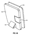
図68〜69は、PED(図示せず)用のケース1600を示す。ケース1600は、PEDを収容し、固定し、また持ち運ぶよう構成することができ、また本明細書に記載したすべてのケースにつき説明した、さまざまな特徴及び実施形態の任意の組合せをも設けることができる。図示するように、ケースには、ケース1600が、キックスタンド1604の向きに基づいて(例えば、キックスタンドを展開したか否かに基づいて)、スタンドとして機能させることができるよう構成した、キックスタンド1604を1つ以上設けることができる。特定の実施形態において、キックスタンド1604を、ケース1600を、直立した及び/又は上昇した状態で立て掛けるのに使用しないとき、ケース1600内に引っ込ませることができ、また図示のように、ケース1600から外方に回転することができる。キックスタンド1604は、ケースが、PEDをほぼ直立した及び/又は上昇した状態で立て掛けてスタンドとして機能するようにできる。第1キックスタンド1604は、図68に示すように、ケース1600を、横長表示の向きで、直立した及び/又は上昇した状態にして立て掛けることができ、第2キックスタンド1604は、図69に示すように、ケース1600を、縦長表示の向きで、直立した及び/又は上昇した状態にして立て掛けることができる。
68-69 show a
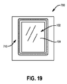
ケース1600は、ケース1600に挿入したPEDの上に配置し、またPEDをほぼ包み込む及び/又は保護するよう構成したカバー1602を設けることができる。特定の実施形態において、カバー1602は、ケース1600にスナップ嵌合することができ、これによって内部に配置したPEDを包み込むことができる。他の実施形態において、カバー1602は、任意な他の機械的手段を用いて、ケース1600にストラップ固定又は固定することができる。特定の実施形態において、カバー1602は、PEDを使用しないときに、ケース1600内に配置したPEDを保護するのに使用することができる。他の実施形態において、カバー1602は、ユーザーがそれを通してPEDを見る及び/又は操作することが可能な透明な窓を設けることができ、これによりカバー1602は、使用時及び不使用時の双方でPED上に配置したままにすることができる。特定の実施形態において、カバー1602に設けた窓は、恒久的に開放したまま、又は選択的に開放可能とすることができる。
The
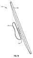
図70は、PED(図示せず)用のハンドヘルドホルダ1700を示す。ハンドヘルドホルダ1700は、ケース1702、及び回転可能な結合機構1706を介してケース1702に結合したハンドポケット1704を有する構成とすることができる。特定の実施形態において、回転可能な結合機構1706は、グロメット又は本明細書に記載した他のあらゆる回転可能な連結部及び/又は機構とすることができ、またケース1702にではなく、PEDに直接結合することができる。ケース1702は、PEDを収容し、固定し、また持ち運ぶよう構成することができ、本明細書に記載したすべてのケースにつき説明した、さまざまな特徴及び実施形態の任意の組合せをも設けることができる。さらに、ハンドポケット1704は、ポケット、ストラップ、ポーチ、ノブ、ハンドル及びユーザーの手若しくは体の他の一部で掴むことができる、又はハンドポケット1704に固定する、任意の相互作用部とすることができる。
FIG. 70 shows a
回転可能な結合機構1706は、ハンドポケット1704に対してさまざまな向きで見ることができるように、PEDをケース1702に配置することを可能にする。例えば、特定の実施形態において、ユーザーはハンドポケット1704を特定の位置に(例えば、ハンドポケット1704又は類似するものに手を固定することで)固定し、回転可能な結合機構1706を使用してハンドポケット1704に対する、さまざまな方向にケース1702を回転させることができる。特定の実施形態において、回転可能な結合機構1706は、回転可能な結合機構をロックしない位置から移動させるために、回転可能な結合機構1706が、より高い回転抵抗を必要とする1つ以上のロック位置を有するよう構成することができる。例えば、回転可能な結合機構1706は、ハンドポケット1704に対してケース1702を、縦長表示及び横長表示の向きにしたときのロック位置を含むことができる。
A
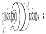
図71〜73は、回転可能な結合機構1706を示す。回転可能な結合機構1706は、本明細書に記載したすべてのケースにでも設けることができ、1つ以上の望ましい向き(例えば、横長表示及び/又は縦長表示の向き)にPEDの向きを変更する設計に使用することができる。回転可能な結合機構1706は、ほぼいかなる円柱形状(例えば、長いシャフト、ホッケーのパックに似た短円柱)とすることができ、互いに相対回転して、1つ以上のロック位置を生ずるよう構成した、2つの相補的なハーフ1708,1710を有する構成とすることができる。相補的なハーフ1708,1710の表面は、ロック位置をもたらすための、1つ以上の突起1712及び1つ以上の窪み1714を設けることができる。図72に示すように、第1ハーフ1708の突起1712は、第2ハーフ1710の窪み1714と補完し合い、互いに合致する。同様に、第2ハーフ1710の突起1712は、第1ハーフ1708の窪み1714と補完し合い、互いに合致する。第1ハーフ1708が第2ハーフ1710に対して回転するにつれて、第1ハーフ1708の突起1712は、ロックしない位置(すなわち、第1ハーフ1708の突起1712が、第2ハーフの突起1712と隣接する)、とロック位置(すなわち、第1ハーフ1708の突起1712が、第2ハーフ1710の窪み1714と隣接する)の間で回転することができる。突起1712及び窪み1714は、図示のように入れ替えることができ、また波形状、相補的な歯及び類似するものを含む、任意の機能的に適切な形状にすることができる。
FIGS. 71-73 show a
特定の実施形態において、突起1712は丸みの付いた形状とし、また相補的なハーフ1708,1710が相対回転するとき、第1ハーフ1708における第1突起1712が、対向する第2ハーフ1710における第2突起1712を第1突起でスムーズに回転及び通過させるよう構成することができる。同様に、窪み1714は、丸みの付いた形状とすることができる。さらに、突起1712から窪み1714への移行は、図示のように、ゆるやかに丸みを付けた表面を形成するために、途切れのない連続的なものとすることができる。したがって、相補的なハーフ1708,1710は、容易に相対回転することができ、これによって、相補的なハーフ1708,1710が分離することなく、互いに隣接する間、ロック位置相互間で移行することができる。
In certain embodiments, the
他の実施形態において、突起1712は、丸みの付いた形状ではなく、鋸歯状にすることができる。例えば、突起1712は、相補的な鋸歯とすることができる。いくつかの実施形態において、歯は三角形の形状にし、突起1712と窪み1714との間で交互配置することができる。特定の実施形態において、相補的なハーフ1708,1710は、回転を開始する前に引き離し、分離させる必要がある場合がある。他の実施形態において、突起1712から窪み1714への移行は、より際立った及び/又は不連続的なものにすることができ、これにより、各突起1712と窪み1714との間には分離を生ずる。
In other embodiments, the
図示の実施形態において、各ハーフ1708,1710には、4個の突起1712及び4個の窪み1714を設ける。したがって、回転可能な結合機構1706は、4個のロック位置を有する。4個のロック位置はそれぞれ90°の回転に対応することができる。図から分かるように、より小さな回転角度でロック位置が増えるように、突起1712及び窪み1714を付加的に設けることができる。さらに、より少ないロック位置にするために、より少ない突起1712及び窪み1714を設けることもできる。
In the illustrated embodiment, each
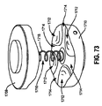
回転可能な結合機構1706は、さらに、軸をなすよう構成したロッド又は弾性ピース等の連結部材1716設け、この軸の周りにハーフ1708,1710が回転する構成とすることができる。連結部材1716は、さらに、相補的なハーフ1708,1710を互いに固定する。いくつかの実施形態において、連結部材1716は、第1ハーフ1708及び第2ハーフ1710を押し付け合うよう構成した、1つ以上の偏倚部材を設けることができる。例えば、連結部材1716は、2つの相補的なハーフ1708,1710に挿通し、2つの相補的なハーフ1708,1710を互いに押し付け合うために、2つの相補的なハーフ1708,1710の外側にばね1718でばね負荷することができる。代案として、図73に示すように、連結部材1716自体に、偏倚力を生ずることができるばね1718又は弾性材料等の偏倚部材を設けることができる。偏倚力は相補的なハーフ1708,1710を互いの方向に向けて押し付け合うようにする。さらに、偏倚力は、回転可能な結合機構1706をロック位置に向けて押圧することができる(すなわち、第1ハーフ1708の突起1712を第2ハーフ1710の窪み1714に隣接する位置に突き当たる位置に向けて、及びその逆に押圧することによって)。他の実施形態において、例えば、重力等の外部力によって、相補的なハーフ1708,1710を互いの方向に押し付け合わせる偏倚力を生ずるようにすることができる。
The
図74〜77は、PED102用の回転可能なケース1800を示す。ケース1800は、PED102を収容し、固定し、保持し、また持ち運ぶよう構成したホルダ1802を有する構成とし、また本明細書で記載したあらゆるケース及び/又はホルダにつき説明した、さまざまな特徴及び実施形態の任意の組合せをも設けることができる。図示のように、ホルダ1802は、PED102をコーナーで機械的に固定することで、PED102を保持するよう構成することができる。特定の実施形態において、ホルダ1802は、圧嵌及び/又はスナップ嵌合を使用して、PED102を保持することができる。
74-77 show a
ケース1800は、ベース部分1804及び支持部分1806を構成するカバー1804,1806をさらに設けることができる。ベース部分1804及び支持部分1806は、折り目1808で結合し、ベース部分1804が、支持部分1806に対してヒンジ的に回動することができるようにする。特定の実施形態において、ベース部分1804及び支持部分1806は、一体的に形成し、折り目1808は、ベース部分1804及び支持部分1806の一部をなすようにすることができる。他の実施形態において、ベース部分1804、支持部分1806及び折り目1808は個別のコンポーネントとすることができる。特定の実施形態において、ホルダ1802は及び/又はカバー1804は、包囲したPED102の保護を行うようにする。例えば、ホルダ1802、ベース部分1804及び/又は支持部分1806は、詰め物、金属、プラスチック、段ボール、ゴム及び/又は他の材料、又はこれらの組合せで補強することができる。
The
特定の実施形態において、折り目1808は、望ましい抵抗及び/又は弾性特性を得るために、材料におけるさまざまな折り目、曲げ部及び/又は湾曲部とすることができる。例えば、折り目1808は、ユーザーがベース部分1804と支持部分との間の相対角度を選択的に1つ以上の所定角度に変化させることを可能にする、双安定、三安定又はN回安定な折り畳み部として機能するよう構成することができる。N回安定の折り畳み部を活用するいくつかの実施形態において、支持部分1806はベース部分1804に対して1つ以上の所定位置に効果的にスナップ嵌合することができる。
In certain embodiments, the
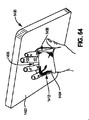
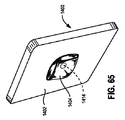
ベース部分1804は、ヒンジ部1812を介して、垂直支持体1810に結合することができる。特定の実施形態において、垂直支持体1810は、PED102のディスプレイ104を見ることができるようにする、直立した及び/又は上昇した状態で、ホルダ1802を部分的に立て掛けるよう構成することができる。垂直支持体1810は、回転機構1814を介して、ホルダ1802に結合して、これにより、垂直支持体1810に対するホルダ1802の可変の回転を可能にする。例えば、図77に示すように、回転機構1814には、垂直支持体1810及びホルダ1802に固定した回転グロメットを設けることができ、これにより、垂直支持体1810に対するホルダ1802の可変の回転を可能にする。他の実施形態において、回転機構1814としては、ラチェット式のスイベル若しくはピボット、ボール−ソケット機構、一時的接着剤、釈放可能ラッチ、クリップ、1つ又はそれ以上のボタン、吸着カップ及び/又は回転固定を可能にする1つ以上のストラップがある。特定の実施形態において、回転機構1814は、特定の回転方向の向き(図75に示すように縦長表示及び/又は図74に示すように横長表示)となるようスナップ嵌合することができ、また異なる特定の向きに移行するためには回転力を必要とする場合がある。別の実施形態において、回転機構1814は、特定向きにスナップ嵌合することができないが、任意の数の向きに関節のような回動を可能にする場合がある。さらに、特定の実施形態において、垂直支持体1810は、例えば、固定の及び/又はヒンジ連結機構を含む非回転連結部を介して、ホルダ1802に結合することができる。
垂直支持体1810は、摺動トラック又は同様の調節機構を使用してその長さを調節可能に構成することができる。いくつかの実施形態において、垂直支持体1810の長さを調節することで、ベース部分1804とホルダ1802の間の相対距離を調整することができる。特定の実施形態において、垂直支持体1810は、選択的なロック機構等を介して、1つ以上の所定位置に調整するよう構成することができる。他の実施形態において、垂直支持体1810は固定の長さにすることができる。
The
図77に示すように、垂直支持体1810の背面には、1つ以上の溝1816を設けることができる。いくつかの実施形態において、溝は、支持部分1806の端縁を収容するよう構成することができる。PED102を直立した及び/又は上昇した位置で支持するようケース1800を構成するためには、ベース部分1804を、垂直支持体1810に対してヒンジ1812の周りに回転させ、また作業台に配置することができる。支持部分1806の角度は、折り目1808を介して、ベース部分1804に対して調整することができ、それによって、ホルダ1802内に包囲したPED102の見る角度を調節する。所望の角度が得らとき、支持部分1804の端部は、1つの溝1816に配置し、これにより、所望の視認角度にケース1800を保持することができる。いくつかの実施形態において、支持部分1806の端部は、圧嵌により溝1816に固定することができる。他の実施形態において、選択的な固定機構、例えば磁気的連結、スナップ、ボタン、クリップ等を使用して、溝1816内に支持部分1806の端部を固定することができる。
As shown in FIG. 77, one or
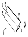
PED102を使用しないとき、ユーザーによってケース1800を図76に示すように、収納状態に形態替えすることができる。ケース1800を収納状態への形態替えをするためには、ベース部分1804及び支持部分1806をヒンジ1812の周りに関節のような回動をさせ、PED102のディスプレイをカバーする。このような形態において、折り目1808は、ベース部分1804と支持部分1806がほぼ同一平面となるよう調整することができる。特定の実施形態において、収納状態へのケース1800の形態替えには、摺動トラック機構等を使用して、垂直支持体1810の長さを調整することを必要とする。いくつかの実施形態において、ベース部分1804と支持部分1806は、収納形態で、磁気的連結、1つ以上の釈放可能クリップ、ストラップ及び/又はケース1800を収納形態に選択的にロックし、また選択的に釈放することを可能にする他のロック機構を介して、ホルダ1802及び/又はPED102に固定することができる。
When the
図78〜81は、PED102の支持体1900を示す。支持体1900は、PED102を収容し、固定し、保持し、また持ち運ぶよう構成したホルダ1902,1904を有し、また本明細書で説明したすべてのケース及び/又はホルダのさまざまな特徴及び実施形態の任意の組合せをも設けることができる。図示のように、ホルダ1902,1904は、圧嵌機構等を使用して、PED102を機械的に固定することで、PED102を保持するよう構成することができる。特定の実施形態において、ホルダ1902,1904には、主要部1902及び選択的に取り外し可能な頂部1904を設けることができる。頂部部分1904を主要部分1902から取り外したとき、PED102を主要部分1902内に配置することができ、また選択的なラチェット機構1906等を使用して、頂部部分1904を主要部分1902に確実に結合したとき、PED102を主要部分1902内に確実にロック、することができる。いくつかの実施形態において、主要部分1902は及び頂部部分1904は、1つ以上のリブ及び/又は溝若しくは同様の整列機構を使用して、整列させることができる。
78-81 show a
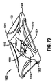
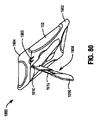
特定の実施形態において、ホルダ1902,1904には、さらに、見る位置において、ホルダ1902,1904を立て掛けるよう構成及び配置することができる1つ以上のキックスタンド1908を設けることができる。キックスタンド1908は、図78及び図79に示すように、不使用時にはホルダ1902,1904内に引っ込ませることができ、また図80及び図81に示すように、ホルダ1902,1904を立て掛けるために、ヒンジ1910を介して、ホルダ1902,1904から外方に回転させることができる。このようにして、キックスタンド1908は、支持体1900が、ホルダ1902,1904に配置したPED102をほぼ直立した及び/又は上昇した位置で支持するようスタンドとして機能することを可能にする。特定の実施形態において、ホルダ1902,1904に対するキックスタンド1908の角度を調整することで、支持体1900内に配置したPED102の視認角度を調整することができる。例えば、キックスタンド1908をホルダ1902、1904からヒンジ1910を介して、外方に回転する度合いを大きくすることで、PED102を、より直立度及び/又は上昇度が少ない角度で見ることができる。同様に、キックスタンド1908がホルダ1902,1904から外方に回転する度合いを小さくすることで、PED102は、直立度及び/又は上昇度がより大きい角度で見ることができる。特定の実施形態において、ヒンジ1910は、例えば、ラチェット機構等を使用して、キックスタンド1908を、1つ以上の所定角度に、ホルダ1902,1904から外方に回転するよう構成することができる。
In certain embodiments, the
キックスタンド1908の長さは、摺動及び/又はラチェット機構1912を使用して調整することができる。特定の実施形態において、キックスタンド1908の長さを調整することで、支持体1900内に配置したPED102の関連する視認角度を調整することができる。例えば、キックスタンド1908を伸ばすことで、PED102はより直立した及び/又は上昇した角度で見ることができる。同様に、キックスタンド1908を短くすることで、PED102は、より直立度及び/又は上昇度の少ない角度で見ることができる。特定の実施形態において、キックスタンド1908の長さは、選択的なロック機構1914等を介して、1つ以上の所定位置に調整するよう構成することができる。他の実施形態において、キックスタンド1908は固定の長さとする。
The length of the
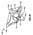
レスト1916は、キックスタンド1908の端部に配置し、支持体1900を使用するときに、作業面の上に配置するように設定することができる。特定の実施形態において、支持体1900を1つ以上の向きにするとき、レスト1916には作業面に平行に位置決めされるよう構成した端縁を1つ以上設けることができる。例えば、図80に示すように、レスト1916には、PED102を縦長表示の形態で見るとき、作業面に平行に着座するよう構成した端縁を設けることができる。同様に、図81に示すように、レスト1916には、PED102を横長表示の形態で見るときに、作業面に平行に位置決めされるよう構成した端縁を設けることができる。このようにして、支持体1900を持ち上げ、また回転させることで、内部に配置したPEDを横長表示及び/又は縦長表示の向きで見ることができる。特定の実施形態において、レスト1916は、レスト1916が作業面に沿って、簡単に滑ることを防止するよう構成した材料(例えば、ゴム等)を含む場合がある。
The
図82〜84は、PED102用の回転可能な支持体2000を示す。支持体2000は、PED102を収容、固定し、保持し、また持ち運ぶよう構成したホルダ2002,2004を有し、本明細書で説明した全てのケース及び/又はホルダにつき説明した、さまざまな特徴及び実施形態の任意の組合せをも設けることができる。図示のように、ホルダ2002,2004は、圧嵌機構等を使用して、PED102を機械的に固定することで、PED102を保持するよう構成することができる。特定の実施形態において、ホルダ2002,2004には、主要部分2002及び選択的に取り外し可能な頂部部分2004を設ける。PED102は、頂部部分2004を主要部分2002から取り外したとき主要部分2002内に配置することができ、また選択的なラチェット機構等を使用して、頂部2004を主要部2002に確実に結合したとき、PED102は、主要部分2002に確実にロックすることができる。特定の実施形態において、主要部分2002及び/又は頂部分2004に一体に形成した窪み2006はユーザーが使用して、主要部分2002から頂部部分2004を取り外し易くする。いくつかの実施形態において、主要部分2002及び頂部部分2004は、1つ以上のリブ及び/又は溝又は同様の整列機構を使用して整列させることができる。
82-84 show a
ホルダ2002,2004は、PED102のディスプレイ104をユーザーが見ることを可能にする窓を画定することができる。さらに、ホルダ2002、2004は、ホルダ2002、2004を通してPED102のアクセサリ(例えば、カメラ)及び/又はインタフェース(例えば、ボタン、スイッチ、ノブ等)をアクセスできるようにする、1つ以上のアクセス窓2008を設けることができる。
ホルダ2002,2004は、さらに、ホルダ2002,2004を視認位置に立て掛けるように、構成及び配置することができるキックスタンド2010を1つ以上設けることができる。キックスタンド2010は、図82に示すように、不使用時には、ホルダ2002,2004内に引っ込ませることができ、図83に示すように、ホルダ2002,2004を立て掛けるために、ヒンジ2012を介して、ホルダ2002,2004から外方に回転させることができる。このように、キックスタンド2010は、支持体2000が、ホルダ2002、2004に配置したPED102をほぼ直立した及び/又は上昇した位置で立て掛けるスタンドとして機能することを可能にする。特定の実施形態において、ホルダ2002,2004に対するキックスタンド2010の相対角度を調整することで、支持体2000内に配置したPED102の視認位置を調整することができる。例えば、キックスタンド2010の端部に設けたレスト2014を作業面に配置したとき、キックスタンド2010がホルダ2002,2004からヒンジ2012を介して、外方に回転する度合いを増すことで、PED102を、直立度及び/又は上昇度の少ない角度で見ることができる。同様に、キックスタンド2010の端部に設けたレスト2014を作業面に配置したときに、キックスタンド2010がホルダ2002、2004から外方に回転する度合いを少なくすることで、PED102は、直立度及び/又は上昇度が大きい角度で見ることができる。いくつかの実施形態において、ヒンジ2012は、キックスタンド2010を、1つ以上の所定角度にて、例えば、ラチェット機構等を使用して、ホルダ2002,2004から外方に回転できるよう構成することができる。特定の実施形態において、レスト2014は、レスト2014が作業面に沿って、簡単に滑ることを防止するよう構成した材料(例えば、ゴム等)を設ける。
The
キックスタンド2010の長さは、摺動及び/又はラチェット機構2016を使用して調整することができる。特定の実施形態において、キックスタンド2010の長さを調整することで、支持体2000内に配置したPED102の相対的な見る角度を調整することができる。例えば、キックスタンド2010を伸ばすことで、PED102は直立度及び/又は上昇度が大きい角度で見ることができる。同様に、キックスタンド2010を短くすることで、PED102は、直立度及び/又は上昇度が少ない角度で見ることができる。特定の実施形態において、キックスタンド2010の長さは、選択的なロック機構等を介して、1つ以上の所定位置に調整するように構成することができる。他の実施形態において、キックスタンド2010は固定の長さとする。
The length of the
特定の実施形態において、キックスタンド2010は、回転機構2018を介して、ホルダ2002,2004に結合することができる。特定の実施形態において、回転機構2018には、ヒンジ2012に固定した回転グロメット及びキックスタンド2010を設け、これにより、ホルダ2002,2004に対するキックスタンド2010の可変回転を可能にする。他の実施形態において、回転機構2018としては、ラチェット式のスイベル若しくはピボット、ボール−ソケット機構、一時的接着剤、釈放可能ラッチ、クリップ、1つ以上のボタン、吸着カップ及び/又は回転固定を可能にする1つ以上のストラップがある。特定の実施形態において、回転機構2018は、特定の回転方向の向き(縦長表示の向き及び/又は横長表示の向き)にスナップ嵌合することができ、異なる特定の向きに移行するには回転力をとする。別の実施形態において、回転機構2018は、特定の向きにスナップ嵌合しないが、任意な数の向きに間接動きのような回動を可能にする場合がある。さらに、特定の実施形態において、キックスタンド2010は、例えば、固定の及び/又はヒンジ式の機構を含む非回転連結部を介して、ホルダ2002,2004に結合することができる。
In certain embodiments, the
いくつかの実施形態において、支持体2000は、ホルダ2002,2004を含まず、キックスタンド2010を、直接又は回転機構2018を介してPED102に結合する場合がある。特定の実施形態において、キックスタンド2010及び/又は回転機構2018は、1つ以上のストラップ、バックル、クリップ、接着剤及び/又は、PED102に及び/又はキックスタンド2010及び/又は回転機構2018に一体化した他の機械的構造を使用して、PED102に結合する場合がある。
In some embodiments, the
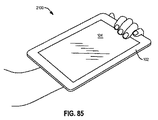
図85〜86は、PED102用のハンドヘルド(手持ち式)ホルダ2100を示す。ハンドヘルドホルダ2100は、PED102を収容し、固定し、保持し、また持ち運ぶよう構成したケース2102を有し、本明細書で記載したすべてのケース及び/又はホルダにつき説明する、さまざまな特徴及び実施形態の任意の組合せをも設けることができる。図示のように、ケース2102は、PED102の外周の周りを機械的に固定することで、PED102を保持するよう構成することができる。特定の実施形態において、ケース2102は、圧嵌及び/又はスナップ嵌合機構を使用して、PED102を保持する。
85-86 show a
ハンドグリップ2104は、ハンドヘルドホルダ2100の背面に設けることができる。特定の実施形態において、ハンドグリップ2104は、ケース2102の背面に結合した回転機構2110に取り付けることができる。ハンドグリップ2104には、センターハブ2108、及びそこから延び、回転機構2110の外周に結合した1つ以上のストラップ2106を設けることができる。ユーザーは体の一部(例えば、図85に示すように、手又は前腕)を、回転機構2110とストラップ2106との間に、滑りこませ、ケース2102をユーザーに固定することができる。特定の実施形態において、ハンドグリップ2104は、回転機構2110と一体的に形成することができる。他の実施形態において、ハンドグリップ2104又はその一部(例えば、ストラップ2106)は、少なくとも回転機構2110の一部を通過する及び/又は包み込むようにする。
The
センターハブ2108には、ある機構を回転させると、その機構から延びる1つ以上のストラップ2106の長さが調整される、該機構を設けることができる。例えば、センターハブ2108を、特定方向に回転させると、1つ以上のストラップ2106の長さを短くすることができる。同様に、センターハブ2108を別の方向に回転させると、1つ以上のストラップの長さを増大させることができる。1つ以上のストラップ2106の長さを調整可能にすることで、ハンドグリップ2104は、ユーザーの体の一部(例えば、手又は前腕)に、そのサイズに関係なく、固定することができるサイズとなる。
The
回転機構2110としては、回転グロメット、ラチェット式のスイベル若しくはピボット、ボール−ソケット機構、一時的接着剤、釈放可能なラッチ、クリップ、1つ以上のボタン、吸着カップ及び/又はハンドグリップ2104をケース2102に回転固定することを可能にする、1つ以上のストラップがある。ストラップ2106及び/又は回転機構2110の内側には、少なくとも部分的にパッド及び/又は軟らかい材料(例えば、マイクロファイバ)で内張りし、快適な使用感が得られるようにすることができる。特定の実施形態において、回転機構2110は、ユーザーの手のひらに快適に順応するように、円形形状とする。他の実施形態において、回転機構2110は、任意の適当な及び/又は人間工学的な形状にすることができる。
The rotating mechanism 2110 includes a rotating grommet, a ratchet swivel or pivot, a ball-and-socket mechanism, a temporary adhesive, a releasable latch, a clip, one or more buttons, a suction cup and / or a
ユーザーが、ハンドグリップ2104を体の一部に固定することで、回転可能なホルダ2100を身に着けるとき、そのユーザーは、ハンドグリップ2104の相対位置を定位置に固定しながら、ケース2102を回転機構2110の周りに回転させることで、ケース2102内に配置したPED102を見る向きを変更することができる。例えば、ユーザーは、図85に示すように、PED102を縦長表示の向きで見ることができるように、回転機構2110の向き決めをすることができる。回転力をPED102及び/又はケース2102に加えることで、ケース2102は、回転機構2110の周りに回転させることができ、また例えば、横長表示の向きを含む,異なる向きで見ることができるようになる。特定の実施形態において、回転機構2110は、例えば、縦長表示及び/又は横長表示を含む、1つ以上の所定の向きに、効果的にスナップ嵌合するよう構成する。
When the user wears the
特定の実施形態において、ホルダ2100は、ケース2102を有さず、ハンドグリップ2104を、直接又は回転機構2110を介して、PED102に結合する場合がある。特定の実施形態において、ハンドグリップ2104及び/又は回転機構2110は、1つ以上のストラップ、バックル、クリップ、接着剤及び/又はPED102及び/又はハンドグリップ2104及び/又は回転機構2110に一体化した他の機械構造を使用して、PED102に結合する場合がある。
In certain embodiments, the
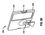
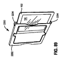
図87〜89は、PED102用の支持体2200を示す。支持体2200は、PED102を収容し、固定し、保持し、及び持ち運ぶよう構成したケース2202を有し、本明細書に記載したすべてのケース及び/又はホルダにつき説明した、さまざまな特徴及び実施形態のいかなる組合せをも設けることができる。図示のように、ケース2202は、圧嵌機構等を使用して、PED102を機械的に固定することで、PED102を保持するよう構成することができる。特定の実施形態において、PED102は、図89に示すように、PED102を収容するよう構成した、ケース2202の端部に配した、1つ以上の固定クリップ2204によって、ケース2202内に固定する場合がある。
87-89 show a
いくつかの実施形態において、ケース2202は、ユーザーがPED102のディスプレイ104を見ることができるように、ウィンドウを画定する場合がある。さらに、ケース2202にはPED102を露出させる部分を1つ以上設けることができる。特定の実施形態において、これらの部分は、PED102をケース2202から取り除くことに役立つ場合がある。
In some embodiments,
支持体2200には、さらに、視認位置にて、支持体2200を立て掛けるよう構成及び配置することができるケース2202に結合したキックスタンド2206を1つ以上設けることができる。特定の実施形態において、キックスタンド2206は、本明細書に記載した、すべてのキックスタンドにつき説明した、さまざまな特徴及び実施形態の任意の組合せを設けることができる。例えば、キックスタンド2206は、図82〜84に示す回転機構2018に似た回転機構を使用して、回転自在にケース2202に結合することができる。特定の実施形態において、支持体2200内に配置したPED102の視認する向き(例えば、縦長表示及び/又は横長表示の向き)は、キックスタンド2206をケース2202に対して回転させることで、調整することができる。さらに、キックスタンド2206は、図82〜84に示すキックスタンド2010と同様に、調整することができる。
The
特定の実施形態において、ケース2202は、PED102に関連する1つ以上のアクセサリ(付属品)2210を、ケース2202に固定及び保持(すなわち、収納)するよう構成した収納領域2208を画定する。特定の実施形態において、1つ以上のアクセサリ2210としては、任意のPED102インタフェース(例えば、キーボード、マウス、ヘッドホン等)又はアクセサリ(例えば、メモリデバイス、洗浄液等)がある。特定の実施形態において、1つ以上のアクセサリ2210は、収納領域2208内に、圧嵌機構等を使用して、機械的に固定し、保持する。特定の実施形態において、1つ以上のアクセサリは、1つ以上の釈放可能クリップ、ストラップ、又はアクセサリ2210を収納領域2208に選択的にロックし、また収納領域2208から選択的に釈放することを可能にする、他のロック機構を使用して、収納領域2208内に固定する場合がある。
In certain embodiments, the
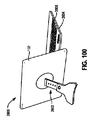
図90〜91は、横長表示の形態となるよう向き決めしたPED102用の回転可能なケース2300を示す。特定の実施形態において、回転可能なケース2300には、PED102を収容し、固定し、保持し、また持ち運ぶよう構成したホルダ(図示せず)を設け、本明細書に記載したすべてのケース及び/又はホルダにつき説明した、さまざまな特徴及び実施形態の任意の組合せをも設けることができる。他の実施形態において、図示のように、回転可能なケース2300は、直接PED102に結合する場合がある。
90-91 show a
回転可能なケース2300は、回転ハブ2304から延び、水平支持体クリップ2306を介して、PED102の外側端縁に結合する、水平支持体2302を1つ以上設けることができる。特定の実施形態において、水平支持体クリップ2306を、圧嵌を使用して、PED102の外端縁に結合する。他の実施形態において、水平支持体クリップ2306は、釈放可能クリップ、ストラップ又は他の選択的なロック機構を使用して、PED102の外端縁に固定する。特定の実施形態において、水平支持体2302の長さは、水平支持体クリップ2306が、PED102の外端縁の周りにしっかりと適合するように、調整する。このようにして、水平支持体2302は、さまざまな寸法を有するPED102を固定するよう調整することができる。
The
特定の実施形態において、回転ハブ2304には、水平支持体2302を、1つ以上の垂直支持体2308に対して回転できるよう構成した回転機構を設ける。回転機構としては、回転グロメット、ラチェット式のスイベル若しくはピボット、ボール−ソケット機構、一時的接着剤、釈放可能ラッチ、クリップ、1つ以上のボタン、吸着カップ及び/又は水平支持体2302を垂直支持体2308に回転固定することを可能にする、1つ以上のストラップがある。
In certain embodiments, the rotating
垂直支持体2308は、垂直支持体クリップ2310を介して、PED102の外端縁に結合することができる。いくつかの実施形態において、垂直支持体クリップ2310を、圧嵌を使用して、PED102の外端縁に結合する。他の実施形態において、垂直支持体2310は、釈放可能クリップ、ストラップ又は他の任意な選択的なロック機構を使用して、PED102の外端縁に固定する。特定の実施形態において、垂直支持体2308の長さは、垂直支持体クリップ2310が、PED102の外端縁の周りにしっかりと適合するように調整する。このように、垂直支持体2308は、さまざまな態様をもつPED102を固定するように調整することができる。
The
水平支持体クリップ2306はそれぞれ、PED支持体2312の端部に取り付けることができる。特定の実施形態において、水平支持体クリップ2306は、PED支持体2312が、水平支持体クリップ2306に対して、1つ以上の方向に回転することができるように、PED支持体2312の端部に回転自在に結合する。このように、PED支持体2312は、PED102を直立した及び/又は上昇した視認位置で立て掛けたときに、PED102を支持するために利用することができる。特定の実施形態において、PED支持体2312の長さは調整することができる。
Each
PED支持体2312の他の端部は、PED支持体2312が、ヒンジ2314に対して1つ以上の方向に回転できるよう構成したヒンジ部2314に結合することができる。ヒンジ部2314は、堅固にベース2316に結合することができる。回転可能なケース2300の使用中、ベース2316は、作業面に配置することができる。PED102は、図90に示すように、ベース2316の頂面にPED102の底端縁を配置することで上昇させ、視認位置に向き決めすることができる。このような形態において、PED102は、ヒンジ部2314及び/又は水平支持体クリップ2306を介して、PED102及び/又はベース2316に対する適切な角度に向き決めしたPED支持体2312によって部分的に支持することができる。いくつかの実施形態において、PED102を見る角度は、PED102及び/又はベース2316に対するPED支持体2312の相対角度を変更することで調整することができる。特定の実施形態において、PED支持体2312は、PED102を、ヒンジ部2314及び/又は水平支持体クリップ2306に設けたラチェット又は同様の機構を使用して、1つ以上の所定の視認角度でPED102を支持するよう構成することができる。
The other end of the
特定の実施形態において、PED102の底端縁は、図1〜2に示す溝116に類似する、ベース2316の頂面に設けた1つ以上の溝(図示せず)に配置ことができる。他の実施形態において、PED102の底端縁は、PED102の底端縁が、表面に沿って簡単に滑ることを防止するよう構成した、ベース2316の頂面に設けた材料(例えば、ゴム、スエード等)の上に配置する。
In certain embodiments, the bottom edge of the
特定の実施形態において、PED102が直立した及び/又は上昇した位置にあるとき、PED102の向きは、回転ハブ2304の周りに水平支持体2302に対してPED102に結合した垂直支持体2308を回転させることで調整することができる。例えば、垂直支持体2308は、図90に示すように、PED102の横長表示の向きに対応する、垂直支持体2308が、水平支持体2302直交する位置まで、回転ハブ2304の周りに回転させることができる。同様に、垂直支持体2308は、PED102の縦長表示の向きに対応する、垂直支持体2308が水平支持体2302に平行な位置まで、回転ハブ2304の周りに回転させることができる。
In certain embodiments, when the
いくつかの実施形態において、ベース2316には、PED102と相互作用するよう構成した統合インタフェース2318を1つ以上設けることができる。例えば、図90に示すように、ベース2316にはキーボードを設けることができる。他の実施形態において、インタフェース2318は、タッチパッド、スピーカー又はベース2316に一体化することができる、他のインタフェース機器を設けることができる。
In some embodiments, the base 2316 can be provided with one or more
PED102を使用しないとき、図91に示すように、ユーザーは回転可能なケース2300を収納状態に形態替えすることができる。回転可能なケース2300を収納状態に形態替えするには、PED102は、PED102のディスプレイ104をベース2316の頂面でカバーするように、PED支持体2312、ヒンジ2314及び/又は水平支持体クリップ2306の周りに回動可能に連結することができる。このような形態において、ベース2316の頂面に配置したインタフェース2318を、外部ダメージから保護することもできる。特定の実施形態において、収納状態へのケース2300の形態替えには、PED支持体2312の長さを調整することが必要な場合がある。いくつかの実施形態において、ベース2316は、収納状態に、磁気的連結、1つ以上の釈放可能なクリップ、ストラップ及び/又は回転可能なケース2300を選択的に収納状態にロックし、また選択的に収納状態から釈放すること可能にする他のロック機構を介して、PED102に固定することができる。
When the
図92〜95は、一体化したキーボード2406を含むPED102用の回転可能なケース2400を示す。特定の実施形態において、回転可能なケース2400には、PED102を収容し、固定し、保持し、また持ち運ぶよう構成したホルダ(図示せず)を設け、本明細書に記載したすべてのケース及び/又はホルダにつき説明した、さまざまな特徴及び実施形態の任意の組合せをも設けることができる。他の実施形態において、図示のように、回転可能なケース2400は、PED102に直接結合することができる。
FIGS. 92-95 show a
回転可能なケース2400は、回転ハブ2408から延び、PED102の外端縁に結合したホルダ2402を有することができる。いくつかの実施形態において、ホルダ2402には、圧嵌を使用して、PED102の外端縁に取り付けたクリップを設けることができる。他の実施形態において、ホルダ2402は、釈放可能クリップ、ストラップ又は任意な他の選択的ロック機構を使用して、PED102の外端縁に固定することができる。特定の実施形態において、ホルダ2402の長さは、ホルダ2402がPED102の外端縁の周りにしっかりと適合するよう調整することができる。このように、ホルダ2402は、さまざまな寸法のPED102を固定するように調整することができる。
The
特定の実施形態において、回転ハブ2408は、ホルダ2402が垂直支持体2404に対して回転できるよう構成した回転機構を有する構成とする。回転機構としては、回転グロメット、ラチェット式のスイベル若しくはピボット、ボール−ソケット機構、一時的接着剤、釈放可能なラッチ、クリップ、1つ以上のボタン、吸着カップ及び/又はホルダ2402を垂直支持体2404に回転固定することを可能にする、1つ以上のストラップがある。特定の実施形態において、垂直支持体2404は、ディスプレイ104を見ることを可能にする、ほぼ直立した及び/又は上昇した位置にて、PED102を支持するよう構成することができる。いくつかの実施形態において、回転ハブ2408は、特定の回転方向の向き(例えば、図92に示すような縦長表示及び/又は図92に示すような横長表示の向き)にスナップ嵌合することができ、また異なる特定の向きに移行するために回転力を必要とする。他の実施形態において、回転ハブ2408は、特定の向きにスナップ嵌合しないが、任意な数の向きに関節運動的な回動を可能にすることができる。さらに、特定の実施形態において、垂直支持体2404は、例えば、固定の及び/又はヒンジ機構を含む非回転連結部を介して、ホルダ2402に結合する。
In certain embodiments, the rotating
垂直支持体2404は、摺動トラック又は同様の調整可能機構を使用して、その長さを調整するよう構成することができる。特定の実施形態において、垂直支持体2404の長さは、選択的ロック機構又は同様の機構を介して、1つ以上の所定位置に調整するよう構成することができる。他の実施形態において、垂直支持体2404は固定長にすることができる。
The
垂直支持体2404は、ヒンジ部2412を介してベース2410に結合することができ、垂直支持体2404がベース2410に対して、1つ以上の方向に回転することを可能にする。特定の実施形態において、ヒンジ部2412を介したベース2410に対する垂直支持体2404の向きを変化させることで、ホルダ2402に配置したPED102の視認角度を調整することができる。
The
特定の実施形態において、ベース2410には、1つ以上の側面及び/又は1つ以上の方向に、ベースから外方に伸びるよう構成した安定化支持体2414を1つ以上設ける。特定の実施形態において、安定化支持体2414は、作業面上におけるベース2410の表面積を増加させ、それによって、使用時の回転ケース2400の安定性を増加させることができる。いくつかの実施形態において、安定化支持体2414は、図94に示すように、不使用時に、トラック又は同様の機構に沿ってベース2410内に滑り込ませることができ、また図92〜93及び図95に示すように、使用時に、より安定したプラットフォームを提供するよう、ベース2410から滑り出させることができる。
In certain embodiments, the
いくつかの実施形態において、ベース2410には、PED102と相互作用するよう構成した1つ以上の統合インタフェース2406を設けることができる。例えば、図92〜93及び図95に示すように、ベース2410にはキーボード2406を設けることができる。他の実施形態において、インタフェース2406としては、タッチパッド、スピーカー又はベース2410に一体化することができる、他のインタフェース機器がある。
In some embodiments, the
PED102を使用しないとき、回転可能なケース2400は、図94に示すように、ユーザーは収納状態に形態替えすることができる。回転可能なケース2400を収納状態に形態替えするには、PED102は、PED102のディスプレイ104をベース2410の頂面でカバーするように、ヒンジ部2412の周りに回動することができる。このような形態において、ベース2410の頂面に配置したインタフェース2406もまた外部ダメージから保護することができる。特定の実施形態において、ケース2400の収納状態への形態替えは、垂直支持体2404の長さを調節する及び/又は特定のPED102の回転方向に達することが必要となる場合がある。いくつかの実施形態において、ベース2410は、収納状態において、磁気的連結、1つ以上の釈放可能クリップ、ストラップ及び/又は回転可能なケース2400を選択的に収納状態にロックし、選択的に収納状態から釈放すること可能にする他のロック機構を介して、PED102に固定する。
When the
図96〜99は、一体化したキーボード2502を有するPED102用の回転可能なケース2500を示す。回転可能なケース2500は、PED102を収容し、固定し、保持し、また持ち運ぶよう構成したホルダ2504を有し、本明細書に記載したすべてのケース及び/又はホルダにつき説明した、さまざまな特徴及び実施形態の任意の組合せをも設けることができる。図示のように、ホルダ2504は、圧嵌機構又は同様の機構を使用して、機械的にPED102を固定することで、PED102を保持するように構成することができる。特定の実施形態において、ホルダ2504は、PED102のコーナーを1つ以上固定することで、PED102を保持することができる。
FIGS. 96-99 show a
ホルダ2504は、回転機構2506に結合することができ、この回転機構2506は、上側ヒンジ部2510を介して、垂直支持体2508に結合することができる。特定の実施形態において、回転機構2506は、ホルダ2504が垂直支持体2508に対して回転するよう構成することができる。回転機構2506としては、回転グロメット、回転ハブ、ラチェット式のスイベル若しくはピボット、ボール−ソケット機構、一時的接着剤、釈放可能ラッチ、クリップ、1つ以上のボタン、吸着カップ及び/又はホルダ2504を垂直支持体2508に回転固定することを可能にする、1つ以上のストラップがある。特定の実施形態において、垂直支持体2508は、ディスプレイ104を見ることを可能にする、ほぼ直立した及び/又は上昇した位置にPED102を支持するよう構成することができる。いくつかの実施形態において、回転機構2506は、特定回転方向の向き(例えば、図98に示すような縦長表示及び/又は図96に示すような横長表示の向き)にスナップ嵌合することができ、別の特定向きに移行するために回転力を必要とする。他の実施形態において、回転機構2506は、特定の向きにスナップ嵌合しないが、任意な数の向きへの回動を可能にする。さらに、特定の実施形態において、垂直支持体2508は、例えば、固定の及び/又はヒンジ機構を含む、非回転連結部を介して、ホルダ2504に結合することができ、上側ヒンジ部2510を介して、直接結合することができる。
The
垂直支持体2508は、その長さを、摺動トラック又は同様の調整機構を使用して、調整できるよう構成することができる。特定の実施形態において、垂直支持体2508の長さは、選択的ロック機構又は同様の機構を介して、1つ以上の所定位置に調整するよう構成することができる。他の実施形態において、垂直支持体2508は固定長にすることができる。
The
垂直支持体2508は、さらに、垂直支持体2508がベース2514に対して1つ以上の方向に回転できるように、下側ヒンジ部2512を介して、ベース2514に結合することができる。特定の実施形態において、下側ヒンジ部2512を介してベース2514に、及び/又は上側ヒンジ部2510を介して、ホルダ2504に対する垂直支持体2508の向きを変化させることで、ホルダ2404に配置したPED102の視認角度を調整することができる。
The
図示のように、ベース2514には、PED102と相互作用するよう構成した1つ以上の一体化インタフェース2502を設けることができる。例えば、図96〜98に示すように、ベース2514には、キーボードを設けることができる。いくつかの実施形態において、インタフェース2502としては、タッチパッド、スピーカー又はベース2514に一体化できる他のインタフェース機器がある。特定の実施形態において、インタフェース2502は、1つ以上の側面及び/又は1つ以上の方向に、ベース2514から外方に突出するよう構成することができる。特定の実施形態において、外方に突出させることで、インタフェース2502は、作業面上におけるベース2514の有効な表面積を増加させることができ、これによって、使用時に回転ケース2500の安定性を増加させることができる。さらに、インタフェース2502を外方に伸ばすことで、インタフェース2502の有効な使用可能面積を増加させることができる。例えば、インタフェース2502がキーボードを有するとき、図96〜98に示すように、キーボードを外向きに伸ばすことにより、キーボードのサイズを大きくすることができる。特定の実施形態において、インタフェース2502は、図99に示すように、不使用時に、トラックに沿って又は、同様の機構でベース2514内に滑り込ませることができ、図96〜98に示すように、使用時に、ベース2514から滑り出させることができる。
As shown, the
PED102を使用しないとき、回転可能なケース2500は、図99に示すように、ユーザーは収納状態に形態替えすることができる。回転可能なケース2500を収納状態に形態替えするには、PED102は、PED102のディスプレイ104をベース2514の頂面でカバーするように、上側ヒンジ部2510及び下側ヒンジ部2512の周り回動することができる。このような形態において、ベース2514の頂面に配置したインタフェース2502もまた外部ダメージから保護することができる。特定の実施形態において、ケース2500の収納状態への形態替えは、垂直支持体2508の長さを調整する及び/又はPED102の特定回転方向の向きにすることを必要とする。いくつかの実施形態において、ベース2514は、収納状態において、磁気的連結、1つ以上の釈放可能クリップ、ストラップ及び/又は回転可能なケース2500を選択的に収納状態にロックし、また選択的に収納状態から釈放すること可能にする他のロック機構を介して、PED102に固定することができる。
When the
図100〜102は、PED102用の支持体2600を示す。図示のように、支持体2600は、PED102を収容し、固定し、保持し、また持ち運ぶよう構成したホルダ(図示せず)を有し、本明細書に記載したすべてのケース及び/又はホルダにつき説明した、さまざまな特徴及び実施形態の任意の組合せをも設けることができる。特定の実施形態において、回転可能なキックスタンド2602は、ホルダに取り付け、ほぼ直立した及び/又は上昇した位置で、ホルダ及びPED102を立て掛けるよう構成することができる。他の実施形態において、図示のように、支持体2600は、PED102に直接結合した回転可能なキックスタンド2602、1つ以上のストラップ、バックル、クリップ、接着剤及び/又は他の同様なアタッチメント造作部を設けることができる。
100-102 show a
特定の実施形態において、回転可能なキックスタンド2602は、図78〜81につき説明したキックスタンド1908と類似の特徴部を組み込むことができる。このようにして、PED102の視認角度は、回転可能なキックスタンド2602をさまざまな方法(キックスタンド2602及びPED102の間の相対角度を変更する、キックスタンド2602の長さを調節する等)で回動させることで、調整することができる。さらに、PED102を見る向きは、回転機構を使用して、PED102に対するキックスタンド2602の相対位置を回転させることで、調整することができる。
In certain embodiments, the
支持体2600には、さらに、いくつかの実施形態において、PED102と相互作用するように設定した、1つ以上の一体化したインタフェース2606を有するカバー2604を設けることができる。例えば、図100〜101に示すように、カバー2604には、キーボードを設けることができる。他の実施形態において、インタフェース2606としては、タッチパッド、スピーカー又はカバー2604に組み込むことができる他のインタフェース機器がある。
The
PED102を使用しないときに、支持体2600は、図102に示すように、ユーザーは収納状態に形態替えすることができる。支持体2600を収納状態に形態替えするためには、カバー2604は、カバー2604でPED102のディスプレイ104を覆い、外部ダメージから保護するように、PED102の側面上に固定することができる。このような形態では、カバー2604の内面に配置したインタフェース2606もまた、外部ダメージから保護することができる。いくつかの実施形態において、カバー2604は、収納形態において、磁気的連結、1つ以上の釈放可能クリップ、ストラップ及び/又はカバー2604を選択的に収納形態にロックし、また選択的に収納形態から釈放すること可能にする他のロック機構を介して、PED102に固定することができる。
When the
図103は、選択的に取り外すことが可能な回転機構2716,2718を介した、回転可能なケース2700の支持パネル2708と固定パネル2702との間の相互作用を示す。特定の実施形態において、回転可能なケース2700は、図23〜32の回転可能なケース800につき説明したさまざまな特徴及び実施形態の任意の組合せをも設けることができる。図示のように、回転可能なケース2700は、PEDを収容し、固定し、保持し、持ち運ぶよう構成した固定パネル2702を有し、本明細書に記載したすべてのケース及び/又はホルダにつき説明した、さまざまな特徴及び実施形態の任意の組合せをも設けることができる。
FIG. 103 shows the interaction between the
回転可能なケース2700には、1つ以上の溝2710を有するベース2706、及び下側部分2712並びにピボットフラップ2714を含む支持パネル2708を設けることができる。選択的に取り外し可能な回転機構2716,2718は、支持パネル2708に結合した後方部分2716及び1つ以上のアクセスポート2704を設けることができる固定パネル2702に結合した前方部分2718を有することができる。特定の実施形態において、後方部分2716は、支持パネル2708のピボットフラップ2714に結合することができる。
The
さまざまな実施形態によれば、選択的に取り外し可能な回転機構2716,2718の前方部分2718は、選択的に取り外し可能な回転機構2716,2718の後方部分2716に整合させ、これにより、固定パネル2702をピボットフラップ2714及び/又は支持パネル2708に回転自在に固定することができる。このようにして、固定パネル2702は、選択的に取り外し可能な回転機構2716,2718の周りで、支持パネル2708に対して、自由に360°回転させることができる。
According to various embodiments, the
特定の実施形態において、グロメットの前方部分2718及び後方部分2716は、製造又は組立中に、合体させ、またユーザーが選択的に分離できるようには構成しない。代案として、ユーザーは、図103に示すように、前方部分2718を後方部分2716から選択的に分離し、固定パネル2702をピボットフラップ2714から取り外すことができるようにする。他の実施形態において、グロメットの前方部分2718及び後方部分2716は、分離不能にし、グロメットは、ピボットフラップ2714及び/又は固定パネル2702から選択的に取り外すことができるようにする。
In certain embodiments, the
図104は、選択的に取り外し可能な回転機構2716,2718及びPED(図示せず)用の回転可能なケース2700の固定パネル2702の相互作用を示す。具体的には、図104は、図示のように、自動車のシートの背部とすることができる表面2720に取り付けた図103の固定パネル2702を示す。別の実施形態において、表面2720は冷蔵庫のドア、壁、ドア、机、窓及び/又は任意な他の適切な表面とすることができる。
FIG. 104 shows the interaction of the selectively removable
固定パネル2702を表面2720に取り付けるために、回転グロメットの後方部分2716は、表面2720に取り付けることができ、前方部分2718を後方部分2716に固定することができ、これによって、固定パネル2702を表面2702に回転可能に固定することができる。特定の実施形態において、後方部分2716は、例えば、接着剤、フック−ループ機構、ボタン、1つ以上のジッパ及び/又はクランプを使用して、表面2720に取り付けることができる。さらに、いくつかの実施形態において、後方部分2716は、表面2720に対して、1つ以上の方向に後方部分2716を回転させることを可能にする機構、例えば、ヒンジ、ボール−ソケット継手等を使用して、表面2720に取り付けることができる。特定の実施形態において、後方部分2716の1つ以上の方向への回転を可能にする機構は、固定パネル2702に配置したPEDの視認角度を、表面2720に対して調整することができる。
To attach the
図105は、ユーザーインターフェース2820を有する回転可能なケース2800を示す。図示のように、回転可能なケース2800は、PED(図示せず)を収容し、固定し、保持し、また持ち運ぶよう構成した固定パネル2802を有し、また本明細書に記載したすべてのケース及び/又はホルダにつき説明した、さまざまな特徴及び実施形態の任意の組合せをも設けることができる。さまざまな実施形態によれば、回転可能なケース2800にはさまざまなアクセスポート(例えば、2804及び2806)を設けることができ、これにより、回転可能なケース2800内に配置したPEDとコネクタプラグ、ケーブル、ヘッドホン、スピーカー及び/又は電源アダプタとのインタフェースがとり易くなる。特定の実施形態において、回転可能なケース2800は、電力、接続性を伝送し、及び/又はPEDから外部機器にヘッドホン用ケーブルをつなぐための内臓コードを有する場合がある。さらに、さまざまな実施形態によると、バッテリは、回転可能なケース2800のパネル又はポケットに内蔵することができる。
FIG. 105 shows a rotatable case 2800 with a
特定の実施形態において、回転可能なケース2800は、支持パネル2808及びベースパネル2810に対して、固定パネル2802を回転させる機能を有する。固定パネル2802を支持パネル2808に回転自在に固定するために、さまざまな回転可能な固定装置のいずれを採用することができる。例えば、ブッシング、フランジ付ブッシング、グロメット、リベット、アイレット、平軸受、軸受及び/又はそれらの組合せを使用して、固定パネル2802を支持パネル2808に回転自在に固定することができる。例えば、図示のように、グロメット2812は、固定パネル2802を支持パネル2808に回転自在に固定するよう構成することができる。いくつかの実施形態において、グロメット2812には、グロメット2812の中心の穴からロゴを見ることができるリングを設けることができる。特定の実施形態において、例えば、ロゴのインサート、近接アラーム、又は他の紛失防止用アクセサリ等を含む、1つ以上の交換可能なアクセサリ及び/又はインサートを、グロメット2812の中心の穴にスナップ嵌合することができる。
In a specific embodiment, the rotatable case 2800 has a function of rotating the fixed
ベースパネル2812は、固定パネル2802が直立した及び/又は上昇した位置にあるとき、固定パネル2802の底端縁を固定するために、溝2814を形成することができる。さまざまな代替の実施形態によれば、直立した及び/又は上昇した位置にある固定パネル2802の底端縁を固定するために、溝2814の位置に摩擦面(例えば、ゴム化した表面等)又は摩擦接触パッチを利用することができる。
The
支持パネル2808は、固定パネル2802を直立した及び/又は上昇した位置に支持するために、固定パネル2802に対する対向力を付与するよう構成することができる。図示のように、支持パネル2808及びベースパネル2810は部分2816で折り曲げた又は曲げた単独パネルとすることができる。さまざまな実施形態によると、ベースパネル2810及び支持パネル2808の相対的比率は、特定用途向けに適合させることができる。さらに、特定の実施形態において、回転可能なケース2800はベースパネル2810に対する1つ以上の角度でPEDを支持するように、また、縦長表示及び横長表示を含む複数の向きで支持するよう構成することができる。
The
特定の実施形態において、回転可能なケース2800は、収納モードにすることができ、この場合、ベースパネル2810が、固定パネル2802に固定したPEDのディスプレイをカバーし、外部ダメージから保護するよう向き決めすることができる。いくつかの実施形態において、ベースパネル2810には、図108に示すように、キーボードを含む、1つ以上の一体化したインタフェース2820を設けることができる。いくつかの実施形態において、インタフェース2820としては、タッチパッド、スピーカーまたはベース2810に一体化できる他のインタフェース機器がある。特定の実施形態において、回転可能なケース2800を収納モードにしたとき、固定パネル2802及び/又はPEDは、インタフェース2820を覆い、外部ダメージから保護することができる。
In certain embodiments, the rotatable case 2800 can be in a stowed mode, where the
当業者であれば、本明細書に開示した基本的な原則から逸脱することなく、上述した実施形態の詳細に変更を加えることができることは理解できるであろう。例えば、本明細書において開示する、見る向きを調整可能にする、回転及び/又は回動システムは、スタンド、マウント、又はPEDを収容するよう構成した他の種類のアクセサリに組み込むことができる。加えて、さまざまな実施形態のいかなる好適な組合せ、又は、それらの特徴をも意図している。さらに、本明細書で開示するいずれの方法は、本明細書において説明した方法を実行するための、1つ以上のステップ又は動作を含むことができる。これら方法、ステップ及び/又は動作は、互いに入れ替えることができる。言いかえれば、実施形態の適切な実施のために、ステップ又は動作の明確な順番が必要でない限り、明確なステップ及び/又は動作の順番及び/又は使用は変更することができる。 Those skilled in the art will appreciate that changes can be made to the details of the above-described embodiments without departing from the basic principles disclosed herein. For example, the rotating and / or pivoting system disclosed herein that allows for adjustable viewing orientation can be incorporated into a stand, mount, or other type of accessory configured to accommodate a PED. In addition, any suitable combination of various embodiments or features thereof are contemplated. Further, any method disclosed herein may include one or more steps or actions for performing the method described herein. These methods, steps and / or actions can be interchanged with each other. In other words, the order and / or use of specific steps and / or actions can be changed unless a specific order of steps or actions is required for proper implementation of the embodiments.
本明細書を通して、「1つの実施形態」、「ある実施形態」、「例の実施形態」についての言及は、その実施形態に関連して説明した特定の機能、構造又は性質は、少なくとも1つの実施形態に含まれるということを意味する。従って、この明細書を通して記載して、引用した言い回し又はそれらを変形させたものは必ずしも、同じ実施形態について言及するものではない。同様に、上述した実施形態の説明において、開示を合理化するために、時として、さまざまな特徴を1つの実施形態、図又はそれらの説明に集めていることを認識しておくべきである。この開示の方法は、しかしながら、あらゆる請求項が、その請求項において明確に記載した特徴よりも、多くの特徴を必要とするという意図を反映するものだと、解釈されるべきものではない。むしろ、発明の態様は、開示した実施形態における1つの全ての特徴よりも少ないものの組合せにある。当業者にとって、本発明において説明する基本的な原則から逸脱することなく、上述の実施形態の詳細に変更を加えることができることは明らかであろう。 Throughout this specification, references to “one embodiment,” “an embodiment,” and “an example embodiment” refer to at least one particular function, structure, or property described in connection with that embodiment. It is meant to be included in the embodiment. Thus, phrases mentioned throughout the specification and cited phrases or variations thereof do not necessarily refer to the same embodiment. Similarly, in the description of the above-described embodiments, it should be recognized that sometimes various features are collected in one embodiment, figure or descriptions thereof to streamline the disclosure. This method of disclosure, however, is not to be interpreted as reflecting an intention that any claim requires more features than are expressly recited in that claim. Rather, the inventive aspects lie in combinations of fewer than all the single features in the disclosed embodiments. It will be apparent to those skilled in the art that changes can be made in the details of the above-described embodiments without departing from the basic principles set forth herein.
Claims (20)
作業面に着座するよう構成したベースパネルと、
前記ベースパネルに回動可能に結合し、前記携帯電子機器を上昇した位置で支持するよう構成した支持パネルであって、
前記ベースパネルに回動可能に結合した下側部分、及び
前記下側部分に回動可能に結合したピボットフラップ
を有する、該支持パネルと、
前記ピボットフラップに結合した回転機構と、及び、
前記回転機構に結合し、該回転機構に結合した背面と、前記携帯電子機器の前記背面の大部分を受け入れて覆うように構成した前面とを有するホルダと
を備え、
前記回転機構は、前記ホルダを前記支持パネルに対して、前記携帯電子機器のディスプレイに平行な面内で回転できるよう構成し、
前記支持パネルは、前記ホルダを、該ホルダの前記前面がアクセス可能となる前記上昇した位置から、前記ホルダの前記前面が前記ベースパネルに面し前記支持パネルが前記ケースの外面に沿って延びる収納位置へと回動させるように構成した、
携帯電子機器用のケース。 In a case for a portable electronic device having a back surface and a display surface ,
A base panel configured to be seated on the work surface;
A support panel that is rotatably coupled to the base panel and configured to support the portable electronic device in a raised position,
A support panel having a lower portion pivotably coupled to the base panel, and a pivot flap pivotally coupled to the lower portion;
A rotation mechanism coupled to the pivot flap; and
A holder having a back surface coupled to the rotation mechanism, a back surface coupled to the rotation mechanism, and a front surface configured to receive and cover most of the back surface of the portable electronic device ;
The rotating mechanism is configured to rotate the holder with respect to the support panel in a plane parallel to the display of the portable electronic device ,
The support panel accommodates the holder from the raised position where the front surface of the holder is accessible, the front surface of the holder facing the base panel, and the support panel extending along the outer surface of the case. Configured to rotate to position ,
Case for portable electronic devices.
内側表面及び外側表面を有するベースパネルであって、前記外側表面は、少なくとも一部が作業面に着座するよう構成した、該ベースパネルと、
前記ベースパネルに回動自在に連結した支持パネルと、
前記支持パネルに結合した回転機構と、
前記回転機構に結合し、また携帯電子機器を固定するよう構成したホルダと
を備え、
前記回転機構は、前記ホルダを前記支持パネルに対して、前記携帯電子機器のディスプレイに平行な面内で回転できるよう構成し、
前記ベースパネル及び前記支持パネルは、収納位置に回動し、この回動により、前記ベースパネル及び前記支持パネルが互いにほぼ平行となり、また前記ベースパネルと前記支持パネルとの間に前記ホルダの少なくとも大部分を保持し、このとき前記ベースパネルのほぼ全体が、前記ホルダに固定した前記携帯電子機器のディスプレイ面に近接する状態となるよう構成し、また
前記ベースパネル及び前記支持パネルは、表示位置に回動し、この回動により、前記支持パネルはある角度位置で前記ホルダを支持する所望角度まで回動し、また前記ホルダは前記ベースパネルの前記内側表面に接触して前記角度位置を保持するよう構成した、
携帯電子機器用のケース。 In cases for portable electronic devices,
A base panel having an inner surface and an outer surface, wherein the outer surface is configured to be at least partially seated on a work surface; and
A support panel rotatably connected to the base panel;
A rotation mechanism coupled to the support panel;
A holder coupled to the rotating mechanism and configured to fix a portable electronic device;
The rotating mechanism is configured to rotate the holder with respect to the support panel in a plane parallel to the display of the portable electronic device ,
The base panel and the support panel are rotated to a storage position, and by this rotation, the base panel and the support panel are substantially parallel to each other, and at least the holder is interposed between the base panel and the support panel. Most of the base panel is held so that almost the entire base panel is close to the display surface of the portable electronic device fixed to the holder, and the base panel and the support panel are displayed at a display position. By this rotation, the support panel rotates to a desired angle for supporting the holder at a certain angular position, and the holder contacts the inner surface of the base panel and holds the angular position. Configured to
Case for portable electronic devices.
作業面に着座するよう構成したベースパネルと、
前記ベースパネルに回動可能に結合し、また前記携帯電子機器を上昇した位置で支持するよう構成した支持パネルであって、
前記ベースパネルに回動可能に結合した下側部分、及び
前記ベースパネルに回動可能に結合したピボットフラップ
を有する、該支持パネルと、
前記ピボットフラップに結合した回転グロメットと、及び、
円形開孔を有し、該円形開孔の位置で前記回転グロメットに結合した背面と、前記携帯電子機器の前記背面の大部分を受け入れて覆うように構成した前面とを有するホルダと
を備え、
前記回転グロメットは、前記ホルダを前記支持パネルに対して、前記携帯電子機器のディスプレイに平行な面内で回転できるよう構成し、
前記支持パネルは、前記ホルダを、該ホルダの前記前面がアクセス可能となる前記上昇した位置から、前記ホルダの前記前面が前記ベースパネルに面し前記支持パネルが前記ケースの外面に沿って延びる収納位置へと回動させるように構成した、
携帯電子機器用のケース。 In a case for a portable electronic device having a back surface and a display surface ,
A base panel configured to be seated on the work surface;
A support panel that is pivotally coupled to the base panel and configured to support the portable electronic device in a raised position;
A support panel having a lower portion pivotably coupled to the base panel and a pivot flap pivotally coupled to the base panel;
A rotating grommet coupled to the pivot flap; and
Has a circular opening, and a holder having a back linked to the rotational grommet in the position of the circular apertures, and a front surface configured to cover accept most of the back of the portable electronic device,
The rotating grommet is configured so that the holder can be rotated with respect to the support panel in a plane parallel to the display of the portable electronic device ,
The support panel accommodates the holder from the raised position where the front surface of the holder is accessible, the front surface of the holder facing the base panel, and the support panel extending along the outer surface of the case. Configured to rotate to position ,
Case for portable electronic devices.
Applications Claiming Priority (7)
| Application Number | Priority Date | Filing Date | Title |
|---|---|---|---|
| US35228610P | 2010-06-07 | 2010-06-07 | |
| US61/352,286 | 2010-06-07 | ||
| US36804710P | 2010-07-27 | 2010-07-27 | |
| US61/368,047 | 2010-07-27 | ||
| US42143110P | 2010-12-09 | 2010-12-09 | |
| US61/421,431 | 2010-12-09 | ||
| PCT/US2011/039287 WO2011156275A2 (en) | 2010-06-07 | 2011-06-06 | Portable electronic device case accessories and related systems and methods |
Publications (2)
| Publication Number | Publication Date |
|---|---|
| JP2013529449A JP2013529449A (en) | 2013-07-18 |
| JP5879337B2 true JP5879337B2 (en) | 2016-03-08 |
Family
ID=45063643
Family Applications (1)
| Application Number | Title | Priority Date | Filing Date |
|---|---|---|---|
| JP2013514251A Active JP5879337B2 (en) | 2010-06-07 | 2011-06-06 | Case accessories for portable electronic devices and related systems and methods |
Country Status (13)
| Country | Link |
|---|---|
| US (6) | US9170611B2 (en) |
| EP (1) | EP2529281B1 (en) |
| JP (1) | JP5879337B2 (en) |
| KR (1) | KR20130082443A (en) |
| CN (2) | CN104391543B (en) |
| AU (2) | AU2011265093B2 (en) |
| BR (1) | BR112012028204A2 (en) |
| CA (2) | CA2908213C (en) |
| DK (1) | DK2529281T3 (en) |
| ES (1) | ES2543617T3 (en) |
| NZ (2) | NZ594007A (en) |
| SG (1) | SG183467A1 (en) |
| WO (1) | WO2011156275A2 (en) |
Families Citing this family (380)
| Publication number | Priority date | Publication date | Assignee | Title |
|---|---|---|---|---|
| US20140197048A1 (en) * | 2007-06-06 | 2014-07-17 | Belkin International, Inc. | Multiple orientation support for electronic device with touch screen and method |
| US20110287402A1 (en) * | 2007-08-02 | 2011-11-24 | Michael Sanford | Method and apparatus for novel embodiments to repurpose eink ereaders as writing devices to enable children to write on digital workbook learning content |
| JP5879337B2 (en) * | 2010-06-07 | 2016-03-08 | ターガス・グループ・インターナショナル・インコーポレイテッド | Case accessories for portable electronic devices and related systems and methods |
| US11134580B2 (en) | 2010-07-08 | 2021-09-28 | Zagg Inc | Protective cover for portable electronic device and associated systems and methods |
| US20120024733A1 (en) * | 2010-07-28 | 2012-02-02 | Openpeak Inc. | Protective element and support structure |
| US8328008B2 (en) | 2010-08-10 | 2012-12-11 | Incase Designs Corp. | Case for electronic tablet |
| USD658187S1 (en) | 2011-03-17 | 2012-04-24 | Incase Designs Corp. | Foldable front cover for electronic tablet |
| USD658188S1 (en) | 2011-03-17 | 2012-04-24 | Incase Designs Corp. | Foldable front cover for electronic tablet |
| CN103348173B (en) * | 2010-09-28 | 2016-03-16 | 伯纳德·约翰·格雷厄姆 | For support or the bearing of plane or tablet computing device |
| US9267641B2 (en) | 2010-10-15 | 2016-02-23 | Jon Simon Gillespie-Brown | Multimedia device stand |
| US20120097831A1 (en) * | 2010-10-21 | 2012-04-26 | Lollygig LLC | Display device case, stand and accessory system |
| TWI363026B (en) | 2010-12-13 | 2012-05-01 | Chi Mei Comm Systems Inc | Multi-functional protecting bag |
| TWI491335B (en) | 2011-01-18 | 2015-07-01 | Chiun Mai Comm Systems Inc | Multi-functional protecting bag |
| US9201185B2 (en) | 2011-02-04 | 2015-12-01 | Microsoft Technology Licensing, Llc | Directional backlighting for display panels |
| US20120217174A1 (en) * | 2011-02-25 | 2012-08-30 | Shao-Chieh Ting | Multifunctional protection device for a flat video product |
| US20120224323A1 (en) * | 2011-03-03 | 2012-09-06 | Shang-Wen Yang | Tablet pc supplementary device |
| US8503857B2 (en) * | 2011-06-16 | 2013-08-06 | Edward Sikorski | Recordable downloadable video audio wedding and photo album and accessories |
| US9218024B2 (en) * | 2011-06-23 | 2015-12-22 | Zagg Intellectual Property Holding Co., Inc. | Accessory and support for electronic devices, systems including the same and methods |
| US20120327580A1 (en) * | 2011-06-23 | 2012-12-27 | Zagg Intellectual Property Holding Co., Inc. | Protective devices and systems for portable electronic devices and associated methods |
| US20120326003A1 (en) * | 2011-06-27 | 2012-12-27 | Solow Michael L | Multi-function tablet computer grip with 360-degree rotating finger ringlet |
| JP2013011977A (en) * | 2011-06-28 | 2013-01-17 | Hakuba Shashin Sangyo Kk | Tablet computer case |
| JP2013011978A (en) * | 2011-06-28 | 2013-01-17 | Hakuba Shashin Sangyo Kk | Tablet computer case |
| US20130016467A1 (en) * | 2011-07-11 | 2013-01-17 | Allen Ku | Leather case with keyboard |
| TW201306583A (en) * | 2011-07-25 | 2013-02-01 | Compal Electronics Inc | Supporting assembly for assembled detachable electronic device and assembled detachable electronic device having the same |
| US8900009B2 (en) * | 2011-08-25 | 2014-12-02 | iOmounts LLC. | Apparatus and methods for supporting an article |
| EP2564722A1 (en) * | 2011-08-31 | 2013-03-06 | Targus Group International, Inc. | Universal case for portable electronic devices |
| FR2980596A1 (en) * | 2011-09-28 | 2013-03-29 | Archos | REMOVABLE KEYBOARD ATTACHMENT FOR DRAWBACK WITH AIMANTATION |
| KR101222173B1 (en) * | 2011-10-07 | 2013-01-17 | (주)펜앤프리 | Mobile phone case and tablet pc case |
| TW201318517A (en) * | 2011-10-19 | 2013-05-01 | Ren-De Chen | Cover with structure for facilitating hold of a device and methods of using the same |
| WO2013058938A1 (en) * | 2011-10-20 | 2013-04-25 | Garland Darryl D | Case and mounting apparatus for a tablet computer |
| EP2607773B1 (en) * | 2011-12-22 | 2017-05-31 | Samsung Electronics Co., Ltd | Display apparatus |
| CN204284838U (en) * | 2011-12-22 | 2015-04-22 | 拓乐组织解决方案公司 | For the containment vessel of electronic equipment |
| JP5173040B1 (en) * | 2012-01-06 | 2013-03-27 | 株式会社東芝 | Television receiver and electronic device |
| CN103402891B (en) * | 2012-01-06 | 2016-05-25 | 路易斯·赫苏安特·特赛 | For adjustable retainer and the lid thereof of panel computer |
| US8867776B2 (en) * | 2012-01-09 | 2014-10-21 | Imation Corp. | Audio speaker frame for multimedia device |
| AU2013208080A1 (en) | 2012-01-09 | 2014-07-24 | Imation Corp. | Wireless audio player and speaker system |
| US9071906B2 (en) | 2012-01-09 | 2015-06-30 | Imation Corp. | Wireless audio player and speaker system |
| US9052414B2 (en) | 2012-02-07 | 2015-06-09 | Microsoft Technology Licensing, Llc | Virtual image device |
| US9354748B2 (en) | 2012-02-13 | 2016-05-31 | Microsoft Technology Licensing, Llc | Optical stylus interaction |
| US9580209B2 (en) | 2012-02-14 | 2017-02-28 | ACCO Brands Corporation | Electronic tablet case with internal easel |
| US8749529B2 (en) | 2012-03-01 | 2014-06-10 | Microsoft Corporation | Sensor-in-pixel display system with near infrared filter |
| US9360893B2 (en) | 2012-03-02 | 2016-06-07 | Microsoft Technology Licensing, Llc | Input device writing surface |
| US8935774B2 (en) | 2012-03-02 | 2015-01-13 | Microsoft Corporation | Accessory device authentication |
| USRE48963E1 (en) | 2012-03-02 | 2022-03-08 | Microsoft Technology Licensing, Llc | Connection device for computing devices |
| US9870066B2 (en) | 2012-03-02 | 2018-01-16 | Microsoft Technology Licensing, Llc | Method of manufacturing an input device |
| US20140031095A1 (en) * | 2012-03-02 | 2014-01-30 | Juan Herrera | Fold out cellular phone case |
| US8873227B2 (en) | 2012-03-02 | 2014-10-28 | Microsoft Corporation | Flexible hinge support layer |
| US9706089B2 (en) * | 2012-03-02 | 2017-07-11 | Microsoft Technology Licensing, Llc | Shifted lens camera for mobile computing devices |
| US9426905B2 (en) | 2012-03-02 | 2016-08-23 | Microsoft Technology Licensing, Llc | Connection device for computing devices |
| US9134807B2 (en) | 2012-03-02 | 2015-09-15 | Microsoft Technology Licensing, Llc | Pressure sensitive key normalization |
| US9075566B2 (en) | 2012-03-02 | 2015-07-07 | Microsoft Technoogy Licensing, LLC | Flexible hinge spine |
| US9064654B2 (en) | 2012-03-02 | 2015-06-23 | Microsoft Technology Licensing, Llc | Method of manufacturing an input device |
| US8693189B2 (en) * | 2012-03-05 | 2014-04-08 | Gregory Thomas | Case for a tablet computer |
| USD713402S1 (en) * | 2012-03-06 | 2014-09-16 | Apple Inc. | Portable display device with case |
| US9310837B2 (en) * | 2012-04-16 | 2016-04-12 | World Richman Manufacturing Corporation | Rotating mechanism for computer or similar device |
| US20150041622A1 (en) * | 2012-04-16 | 2015-02-12 | Iordanka Koleva Mulhern | Rotating Mechanism for Computer or Similar Device |
| TWM439327U (en) * | 2012-04-27 | 2012-10-11 | Chi Mei Comm Systems Inc | Supporting bracket for electronic device |
| US8954124B2 (en) * | 2012-05-05 | 2015-02-10 | Bruce Randall Webber | Roll-back cover for an electronic device |
| CN103389775A (en) * | 2012-05-07 | 2013-11-13 | 联想(北京)有限公司 | Electronic equipment |
| US20130300590A1 (en) | 2012-05-14 | 2013-11-14 | Paul Henry Dietz | Audio Feedback |
| US8851280B2 (en) * | 2012-05-22 | 2014-10-07 | Feng Wen | Tablet cover |
| US20130336717A1 (en) * | 2012-05-31 | 2013-12-19 | James Shelby Gragg | Grommet and Flange holder and mounting system for small devices |
| US10031556B2 (en) | 2012-06-08 | 2018-07-24 | Microsoft Technology Licensing, Llc | User experience adaptation |
| US8947353B2 (en) | 2012-06-12 | 2015-02-03 | Microsoft Corporation | Photosensor array gesture detection |
| US9019615B2 (en) | 2012-06-12 | 2015-04-28 | Microsoft Technology Licensing, Llc | Wide field-of-view virtual image projector |
| US9684382B2 (en) | 2012-06-13 | 2017-06-20 | Microsoft Technology Licensing, Llc | Input device configuration having capacitive and pressure sensors |
| US9073123B2 (en) | 2012-06-13 | 2015-07-07 | Microsoft Technology Licensing, Llc | Housing vents |
| US9459160B2 (en) | 2012-06-13 | 2016-10-04 | Microsoft Technology Licensing, Llc | Input device sensor configuration |
| US9256089B2 (en) | 2012-06-15 | 2016-02-09 | Microsoft Technology Licensing, Llc | Object-detecting backlight unit |
| US9355345B2 (en) | 2012-07-23 | 2016-05-31 | Microsoft Technology Licensing, Llc | Transparent tags with encoded data |
| JP5915434B2 (en) * | 2012-07-26 | 2016-05-11 | カシオ計算機株式会社 | cover |
| CN103847643B (en) * | 2012-07-30 | 2018-06-19 | 钱自德 | Built-in automotive side view blind spot mirror |
| US10361741B2 (en) | 2012-08-02 | 2019-07-23 | GoDirectInc.com, Inc. | Mobile device enclosure system |
| TWI489249B (en) * | 2012-08-08 | 2015-06-21 | Wistron Corp | Portable electronic device and housing structure |
| US8953310B2 (en) | 2012-08-08 | 2015-02-10 | Samuel G. Smith | Magnetic systems for electronic devices and accessories |
| US8964379B2 (en) | 2012-08-20 | 2015-02-24 | Microsoft Corporation | Switchable magnetic lock |
| KR102012958B1 (en) * | 2012-08-29 | 2019-08-21 | 삼성전자주식회사 | Tablet apparatus |
| KR101447457B1 (en) * | 2012-08-31 | 2014-10-07 | (주)블루버드 | Tablet pc |
| US9873380B2 (en) * | 2012-09-02 | 2018-01-23 | Davy Zide Qian | Interior side mirror for side blind spot of a car |
| AU2013100681A4 (en) * | 2012-09-07 | 2013-06-20 | Targus Group International, Inc. | Systems case and keyboard for portable electronic device |
| USD705764S1 (en) | 2012-09-12 | 2014-05-27 | Targus Group International, Inc. | Wallet portable electronic device case |
| US8517172B1 (en) * | 2012-10-01 | 2013-08-27 | Match U International Co., Ltd. | Protective housing assembly for electronic devices |
| US9152173B2 (en) | 2012-10-09 | 2015-10-06 | Microsoft Technology Licensing, Llc | Transparent display device |
| TWM459753U (en) * | 2012-10-11 | 2013-08-21 | Fu-Yi Hsu | Protective sheath |
| US8654030B1 (en) | 2012-10-16 | 2014-02-18 | Microsoft Corporation | Antenna placement |
| EP2908971B1 (en) | 2012-10-17 | 2018-01-03 | Microsoft Technology Licensing, LLC | Metal alloy injection molding overflows |
| WO2014059618A1 (en) | 2012-10-17 | 2014-04-24 | Microsoft Corporation | Graphic formation via material ablation |
| WO2014059624A1 (en) | 2012-10-17 | 2014-04-24 | Microsoft Corporation | Metal alloy injection molding protrusions |
| WO2014062206A2 (en) * | 2012-10-18 | 2014-04-24 | Smith Stephen Lorance | Mobile device grip |
| US9689524B2 (en) * | 2012-10-31 | 2017-06-27 | Hewlett-Packard Development Company, L.P. | Pliable member panel support |
| US8952892B2 (en) | 2012-11-01 | 2015-02-10 | Microsoft Corporation | Input location correction tables for input panels |
| US8786767B2 (en) | 2012-11-02 | 2014-07-22 | Microsoft Corporation | Rapid synchronized lighting and shuttering |
| US8905231B2 (en) * | 2012-11-12 | 2014-12-09 | Quest C. Couch, III | Cover for portable electronic device |
| WO2014078728A1 (en) | 2012-11-16 | 2014-05-22 | Belkin International Inc. | Tablet keyboard case and method of providing the same |
| US20140151257A1 (en) * | 2012-11-30 | 2014-06-05 | Golden Arrow Printing, Co.,Ltd. | Paper made bearing plate capable of supporting electrical device and packaging box thereof |
| US8964382B2 (en) | 2012-11-30 | 2015-02-24 | Hewlett-Packard Development Company, L.P. | Computing device with support member |
| CN105229554A (en) * | 2012-12-05 | 2016-01-06 | 新流量有限责任公司 | The covering of portable electric appts, protection and location |
| CN203759583U (en) | 2012-12-12 | 2014-08-06 | 拓乐组织解决方案公司 | Protective shell used for electronic device |
| US9513748B2 (en) | 2012-12-13 | 2016-12-06 | Microsoft Technology Licensing, Llc | Combined display panel circuit |
| USD740882S1 (en) | 2012-12-20 | 2015-10-13 | Thule Organization Solutions, Inc. | Protective case |
| CN103929909A (en) * | 2013-01-04 | 2014-07-16 | 美泰有限公司 | Protective Case For Portable Electronic Device |
| USD771030S1 (en) | 2013-01-09 | 2016-11-08 | Kevin Alan Tussy | Mobile telephone case |
| US8763795B1 (en) | 2013-01-23 | 2014-07-01 | Targus Group International, Inc. | Dual support flap case |
| USD741867S1 (en) * | 2013-01-31 | 2015-10-27 | GoDirectInc.com, Inc. | Compact tablet computer case |
| US20140209503A1 (en) * | 2013-01-31 | 2014-07-31 | Timothy Charles Angel | Portable, adjustable protective case for electronic devices and methods of use thereof |
| US9176538B2 (en) | 2013-02-05 | 2015-11-03 | Microsoft Technology Licensing, Llc | Input device configurations |
| US20140224676A1 (en) * | 2013-02-05 | 2014-08-14 | M-Edge Accessories, Llc | Low profile protective cover configurable as a stand with integrated battery |
| US10578499B2 (en) | 2013-02-17 | 2020-03-03 | Microsoft Technology Licensing, Llc | Piezo-actuated virtual buttons for touch surfaces |
| US9104372B2 (en) * | 2013-02-28 | 2015-08-11 | Berend Frenzel | Multiple footprint stand for a tablet computer |
| US9638835B2 (en) | 2013-03-05 | 2017-05-02 | Microsoft Technology Licensing, Llc | Asymmetric aberration correcting lens |
| US10178807B2 (en) | 2013-03-26 | 2019-01-08 | Hewlett Packard Enterprise Development Lp | Top loading cartridge |
| CN105103074B (en) * | 2013-03-26 | 2019-04-09 | 慧与发展有限责任合伙企业 | Push up the casket that is loaded |
| US9304549B2 (en) | 2013-03-28 | 2016-04-05 | Microsoft Technology Licensing, Llc | Hinge mechanism for rotatable component attachment |
| US20140291176A1 (en) * | 2013-04-01 | 2014-10-02 | Marware, Inc. | Tablet Computer Cover and Stand |
| GB2512884A (en) * | 2013-04-10 | 2014-10-15 | David Richards | A portable electronic device stand and a method of manufacturing a portable electronic device stand |
| AU2013205074B2 (en) * | 2013-04-13 | 2015-07-09 | Targus International Llc | Case with elastic grip holder |
| USD716783S1 (en) | 2013-04-15 | 2014-11-04 | Targus Group International, Inc. | Slim case |
| US9056696B1 (en) * | 2013-04-30 | 2015-06-16 | Armando Reyes | Portfolio with integrated computer and accessory pockets |
| TWM464715U (en) * | 2013-05-03 | 2013-11-01 | Wistron Corp | Fixing device for fixing a portable electronic device and portable electronic apparatus therewith |
| USD749078S1 (en) * | 2013-05-07 | 2016-02-09 | Antenna79, Inc. | Tablet cover |
| US9552777B2 (en) | 2013-05-10 | 2017-01-24 | Microsoft Technology Licensing, Llc | Phase control backlight |
| US9116670B2 (en) * | 2013-06-21 | 2015-08-25 | Microsoft Technology Licensing, Llc | Surface contact for a support component |
| JP5416856B1 (en) * | 2013-06-24 | 2014-02-12 | 株式会社ディセンター | Portable equipment cover |
| WO2014209343A1 (en) | 2013-06-28 | 2014-12-31 | Hewlett-Packard Development Company, L.P. | Device support stand assembly |
| US9110630B2 (en) | 2013-07-25 | 2015-08-18 | Targus Group International, Inc. | Portable electronic device case with an adhesive panel |
| USD719169S1 (en) * | 2013-07-31 | 2014-12-09 | Brian Dale McBroom | Tablet keyboard cover |
| KR101457359B1 (en) * | 2013-08-06 | 2014-11-10 | 한민형 | A bag with an adjustable board for mobile device users |
| US20150041244A1 (en) * | 2013-08-07 | 2015-02-12 | Rackel Industries Limited | Universal Tablet Holder |
| US9149100B2 (en) * | 2013-08-07 | 2015-10-06 | ACCO Brands Corporation | Case for a portable electronic device |
| US9474345B2 (en) | 2013-08-13 | 2016-10-25 | Apple Inc. | Magnetic related features of a cover for an electronic device |
| US10973293B2 (en) | 2013-08-15 | 2021-04-13 | Urban Armor Gear, Llc | Composite protective case for phones, other portable electronic devices and other apparatus |
| TWD161840S (en) * | 2013-08-28 | 2014-07-21 | 富士康(香港)有限公司 | Mult-function case of electronic device |
| US9485338B2 (en) | 2013-09-04 | 2016-11-01 | Apple Inc. | Features and manufacturing methods for a case for a portable electronic device |
| US9419669B2 (en) | 2013-09-04 | 2016-08-16 | Apple Inc. | Case for an electronic device and manufacturing methods for making a case |
| CN104421583B (en) * | 2013-09-09 | 2016-10-05 | 联想(北京)有限公司 | A kind of electronic equipment |
| USD737276S1 (en) * | 2013-09-20 | 2015-08-25 | Urban Armor Gear, Llc | Protective case for electronic tablet |
| US10078346B2 (en) | 2013-09-21 | 2018-09-18 | Otter Products, Llc | Magnetic mounting system for electronic device |
| US9372507B2 (en) * | 2013-09-28 | 2016-06-21 | Intel Corporation | Adjustable support and a mobile computing device having an adjustable support |
| US9241053B2 (en) | 2013-10-25 | 2016-01-19 | M-Edge International Corp. | Molded shock resistant case for an electronic device |
| US10282566B2 (en) | 2013-11-25 | 2019-05-07 | Hewlett-Packard Development Company, L.P. | Computing device security lock |
| US9874260B2 (en) * | 2013-12-02 | 2018-01-23 | Otter Products, Llc | Case with integrated stand activated by pressure |
| US9128683B2 (en) * | 2013-12-02 | 2015-09-08 | Chih-Juh Wong | Protective case for electronic equipment |
| US9774135B2 (en) * | 2013-12-18 | 2017-09-26 | Hewlett-Packard Development Company, L.P. | Electronic device stand |
| USD734761S1 (en) * | 2013-12-20 | 2015-07-21 | Pelican Products, Inc. | Case for electronic pad |
| US9448631B2 (en) | 2013-12-31 | 2016-09-20 | Microsoft Technology Licensing, Llc | Input device haptics and pressure sensing |
| EP3092541B1 (en) | 2014-01-07 | 2019-07-31 | Otter Products, LLC | Protective enclosure for an electronic device |
| USD731495S1 (en) | 2014-01-07 | 2015-06-09 | Thule Organization Solutions, Inc. | Protective case for an electronic device |
| USD732542S1 (en) | 2014-01-07 | 2015-06-23 | Thule Organization Solutions, Inc. | Protective cover for an electronic device |
| US10761565B2 (en) * | 2014-01-27 | 2020-09-01 | Lenovo (Singapore) Pte. Ltd. | Multi-angle stand for an information handling device |
| US9317072B2 (en) | 2014-01-28 | 2016-04-19 | Microsoft Technology Licensing, Llc | Hinge mechanism with preset positions |
| US9759854B2 (en) | 2014-02-17 | 2017-09-12 | Microsoft Technology Licensing, Llc | Input device outer layer and backlighting |
| US9778702B2 (en) * | 2014-02-27 | 2017-10-03 | Hewlett-Packard Development Company, L.P. | Protective cover for a device |
| KR101565335B1 (en) * | 2014-02-27 | 2015-11-05 | 조영희 | Supporting structure having multifunction |
| US20150253813A1 (en) * | 2014-03-04 | 2015-09-10 | Kyle Nicholas Morrow | Soft mount for tablet format electronic devices |
| US10120420B2 (en) | 2014-03-21 | 2018-11-06 | Microsoft Technology Licensing, Llc | Lockable display and techniques enabling use of lockable displays |
| USD733150S1 (en) * | 2014-03-22 | 2015-06-30 | World Richman Manufacturing Corporation | Reversible case for mobile communications device with rotatable device-holding cradle |
| USD733151S1 (en) * | 2014-03-23 | 2015-06-30 | Malcolm Brierley | Case for an E-reader device with viewing stand and a ‘Y’ shaped ergonomic hand strap |
| USD745013S1 (en) * | 2014-03-24 | 2015-12-08 | Malcolm Brierley | Case for an E-reader device with viewing stand and hand strap |
| USD733152S1 (en) * | 2014-03-24 | 2015-06-30 | World Richman Manufacturing Corporation | Reversible case for mobile communications device |
| USD762218S1 (en) * | 2014-03-28 | 2016-07-26 | World Richman Manufacturing Corporation | Reversible case for mobile communications device with universal device-holding mechanism |
| CN103899889A (en) * | 2014-04-02 | 2014-07-02 | 昆山市张浦镇佳聚辉电子厂 | Electronic products support |
| US10063268B2 (en) * | 2014-04-07 | 2018-08-28 | Logitech Europe S.A. | Portable electronic device support |
| CN105378583B (en) | 2014-04-09 | 2019-12-03 | 微软技术许可有限责任公司 | For calculating the lid with hinge links of equipment |
| KR102107275B1 (en) | 2014-04-10 | 2020-05-06 | 마이크로소프트 테크놀로지 라이센싱, 엘엘씨 | Collapsible shell cover for computing device |
| CN105359055A (en) * | 2014-04-10 | 2016-02-24 | 微软技术许可有限责任公司 | Slider cover for computing device |
| USD734340S1 (en) * | 2014-04-29 | 2015-07-14 | Samsung Electronics Co., Ltd. | Case for electronic device |
| US9958906B2 (en) | 2014-04-30 | 2018-05-01 | Hewlett-Packard Development Company, L.P. | Leaf spring computer device stand |
| US20150342378A1 (en) * | 2014-05-28 | 2015-12-03 | Robert L. Boice, JR. | Notebook cover with integral inflatable pillow |
| USD727919S1 (en) | 2014-06-09 | 2015-04-28 | TouchFire, Inc. | Protective case |
| US9750321B2 (en) | 2014-06-13 | 2017-09-05 | Targus Group International, Inc. | Case for portable electronic devices with internal support |
| USD726192S1 (en) | 2014-06-25 | 2015-04-07 | Htc Corporation | Foldable front cover for electronic device |
| USD770457S1 (en) * | 2014-06-25 | 2016-11-01 | Htc Corporation | Foldable cover for electronic device |
| TWM491321U (en) * | 2014-06-26 | 2014-12-01 | Chicony Electronics Co Ltd | Protection shell |
| US9717314B2 (en) | 2014-06-27 | 2017-08-01 | Targus International Llc | Case for portable electronic devices with shutter stand |
| JP2016013300A (en) * | 2014-07-02 | 2016-01-28 | 坂本ラヂヲ株式会社 | Case for portable terminal |
| TWM496149U (en) * | 2014-07-11 | 2015-02-21 | Ozaki Int Co Ltd | Input device and protective shell and combination thereof |
| USD748097S1 (en) * | 2014-07-25 | 2016-01-26 | Youru Feng | Tablet case |
| US10324733B2 (en) | 2014-07-30 | 2019-06-18 | Microsoft Technology Licensing, Llc | Shutdown notifications |
| US9733504B2 (en) * | 2014-08-07 | 2017-08-15 | Mattel, Inc. | Mobile computer with a detachable frame |
| US9225377B1 (en) | 2014-08-11 | 2015-12-29 | Brookstone Purchasing, Inc. | Modular electronic device case for use with tablet-shaped electronic devices |
| TWM493693U (en) * | 2014-08-18 | 2015-01-11 | Ozaki Int Co Ltd | Keyboard and protection cover and assembly structure thereof |
| USD791754S1 (en) | 2014-08-20 | 2017-07-11 | Urban Armor Gear, Llc | Case for a mobile communications device |
| USD733154S1 (en) * | 2014-08-20 | 2015-06-30 | Urban Armor Gear LLC | Tablet computer case |
| USD744489S1 (en) * | 2014-08-23 | 2015-12-01 | World Richman Manufacturing Corporation | Cradle-case combination for an electronic device |
| USD745525S1 (en) * | 2014-09-08 | 2015-12-15 | Logitech Europe S.A. | Protective folio for an input device |
| USD743406S1 (en) * | 2014-09-15 | 2015-11-17 | Amazon Technologies, Inc. | Tablet device case |
| US9424048B2 (en) | 2014-09-15 | 2016-08-23 | Microsoft Technology Licensing, Llc | Inductive peripheral retention device |
| TWI528889B (en) * | 2014-09-19 | 2016-04-01 | 緯創資通股份有限公司 | Electronic device having support and support kit |
| US9447620B2 (en) | 2014-09-30 | 2016-09-20 | Microsoft Technology Licensing, Llc | Hinge mechanism with multiple preset positions |
| DE212015000238U1 (en) | 2014-10-06 | 2017-06-19 | Thule Inc. | Protective cover for an electronic device |
| USD743967S1 (en) * | 2014-10-15 | 2015-11-24 | Triangus Group Co., Ltd. | Tablet computer case |
| KR101494800B1 (en) * | 2014-10-17 | 2015-02-23 | 주식회사 티씨엠 | Mobile terminal supporter with folding structure |
| USD750085S1 (en) * | 2014-10-21 | 2016-02-23 | Logitech Europe S.A. | Protective folio with keyboard for multiple types of input devices |
| USD744490S1 (en) * | 2014-10-21 | 2015-12-01 | Logitech Europe S.A. | Protective folio for multiple types of input devices |
| USD748635S1 (en) * | 2014-10-21 | 2016-02-02 | Logitech Europe S.A. | Protective folio with keyboard for multiple types of input devices |
| CN106662891B (en) | 2014-10-30 | 2019-10-11 | 微软技术许可有限责任公司 | Multi-configuration input equipment |
| USD744491S1 (en) * | 2014-11-10 | 2015-12-01 | Logitech Europe S.A. | Adjustable protective cover for an input device |
| US20160150067A1 (en) * | 2014-11-21 | 2016-05-26 | Hashmat Khaliqi | Systems and apparatuses for positioning and displaying a mobile device |
| KR101605403B1 (en) * | 2014-12-05 | 2016-03-22 | 엔엠텍코리아 주식회사 | Case for mobile apparatus |
| USD750634S1 (en) | 2015-08-17 | 2016-03-01 | FLB Group Limited | Tablet computer case with detachable stand |
| USD754666S1 (en) * | 2014-12-31 | 2016-04-26 | The Tiffen Company, Llc | Case for image-taking device |
| USD764472S1 (en) * | 2015-01-05 | 2016-08-23 | Logitech Europe S.A. | Protective case and cover for a mobile display device |
| US9991922B2 (en) | 2015-01-05 | 2018-06-05 | Iomounts, Llc | Apparatus and method for supporting an article |
| USD772880S1 (en) * | 2015-01-05 | 2016-11-29 | Logitec Europe S.A. | Protective case and support for a mobile display device |
| US9577694B1 (en) * | 2015-01-06 | 2017-02-21 | Jeffrey M. Albee | Support structure to enable use of tablet computer by persons with limited manual dexterity |
| US9278652B1 (en) | 2015-02-05 | 2016-03-08 | Allstate Insurance Company | Phone holder |
| US9609105B1 (en) | 2015-02-05 | 2017-03-28 | Allstate Insurance Company | Phone holder |
| US9859940B1 (en) | 2015-02-05 | 2018-01-02 | Allstate Insurance Company | Phone holder |
| US9281857B1 (en) | 2015-02-05 | 2016-03-08 | Allstate Insurance Company | Phone holder |
| US9699285B1 (en) | 2015-02-05 | 2017-07-04 | Allstate Insurance Company | Phone holder |
| USD766885S1 (en) | 2015-02-09 | 2016-09-20 | Urban Armor Gear, Llc | Wireless device case |
| USD768123S1 (en) | 2015-02-09 | 2016-10-04 | Urban Armor Gear, Llc | Wireless device case |
| US9287917B1 (en) * | 2015-02-19 | 2016-03-15 | A.G. Findings & Mfg. Co. | Electronic device protective case with convenience features |
| USD762204S1 (en) | 2015-02-26 | 2016-07-26 | Urban Armor Gear, Llc | Wireless device case |
| US9675148B2 (en) | 2015-03-18 | 2017-06-13 | Targus International Llc | Extendable, universal case for portable electronic devices |
| USD765085S1 (en) * | 2015-03-24 | 2016-08-30 | Max Interactive, Inc. | Case for an electronic device |
| US9986805B2 (en) | 2015-03-30 | 2018-06-05 | Otter Products, Llc | Protective enclosure for an electronic device |
| USD764473S1 (en) * | 2015-04-01 | 2016-08-23 | Incipio, Llc | Device case |
| WO2016167564A1 (en) * | 2015-04-15 | 2016-10-20 | 신웅수 | Terminal support stand, terminal case, and terminal assembly |
| USD763855S1 (en) * | 2015-04-23 | 2016-08-16 | Griffin Technology, Inc. | Tablet computer case |
| DE202015102126U1 (en) * | 2015-04-28 | 2015-05-18 | Klaus Englert | Portable loudspeaker system with large sound and resonance volume based on a sound panel with reflection and resonance effect |
| US10076168B2 (en) * | 2015-05-20 | 2018-09-18 | World Richman Manufacturing Corporation | Pivot panel case construction for an electronic device |
| USD765663S1 (en) * | 2015-05-27 | 2016-09-06 | Asustek Computer Inc. | Protective cover for a portable electronic device |
| US10222889B2 (en) | 2015-06-03 | 2019-03-05 | Microsoft Technology Licensing, Llc | Force inputs and cursor control |
| US10416799B2 (en) | 2015-06-03 | 2019-09-17 | Microsoft Technology Licensing, Llc | Force sensing and inadvertent input control of an input device |
| GB201509751D0 (en) * | 2015-06-05 | 2015-07-22 | Hartley & Marks Publishers Inc | Tablet case and method of manufacture |
| KR102158297B1 (en) | 2015-06-08 | 2020-09-21 | 박진우 | Protective cases for smart devices with a rotating swivel and tilt angle adjustable secondary display device |
| USD763856S1 (en) * | 2015-06-17 | 2016-08-16 | Max Interactive, Inc. | Case for an electronic device |
| US9752361B2 (en) | 2015-06-18 | 2017-09-05 | Microsoft Technology Licensing, Llc | Multistage hinge |
| USD757018S1 (en) * | 2015-06-19 | 2016-05-24 | Joseph Pearce | Protective case for a tablet computer |
| US9864415B2 (en) | 2015-06-30 | 2018-01-09 | Microsoft Technology Licensing, Llc | Multistage friction hinge |
| KR102427504B1 (en) | 2015-07-15 | 2022-08-02 | 박진우 | Protective cases for mobile devices, with a detachably mountable secondary display device |
| USD763857S1 (en) * | 2015-07-17 | 2016-08-16 | Blackberry Limited | Electronic device shell |
| US10058155B2 (en) | 2015-07-19 | 2018-08-28 | Otter Products, Llc | Protective case system |
| USD766907S1 (en) | 2015-08-05 | 2016-09-20 | Urban Armor Gear, Llc | Case for a computing device |
| USD766249S1 (en) | 2015-08-05 | 2016-09-13 | Urban Armor Gear, Llc | Case for a computing device |
| US9823704B2 (en) * | 2015-08-14 | 2017-11-21 | Urban Armor Gear, Llc | Protective case for a computing device with adjustable stand |
| EP3193233A1 (en) * | 2015-08-19 | 2017-07-19 | World Richman Manufacturing Corporation | Universal device-holding case construction with magnetic fastener feature |
| US9971379B2 (en) * | 2015-08-26 | 2018-05-15 | Apple Inc. | Attachment features for an accessory device |
| CN105120037A (en) * | 2015-09-27 | 2015-12-02 | 陈安炳 | Inclined waterproofing tumbler-like mobile phone fitting |
| USD795238S1 (en) * | 2015-10-02 | 2017-08-22 | Ye Eun Kim | Mobile phone case |
| US10884453B2 (en) | 2015-10-09 | 2021-01-05 | Urban Armor Gear, Llc | Protective case for a computing device and method of use |
| US10061385B2 (en) | 2016-01-22 | 2018-08-28 | Microsoft Technology Licensing, Llc | Haptic feedback for a touch input device |
| US10798840B2 (en) * | 2016-03-14 | 2020-10-06 | Micron Technology, Inc. | Folding device stand for portable devices |
| US10344797B2 (en) | 2016-04-05 | 2019-07-09 | Microsoft Technology Licensing, Llc | Hinge with multiple preset positions |
| CN105629480A (en) * | 2016-04-06 | 2016-06-01 | 众景视界(北京)科技有限公司 | Screen position regulation device of head-wearing visual device and head-wearing visual device |
| US9901796B2 (en) * | 2016-04-25 | 2018-02-27 | Fred Murray | Smart phone holding system |
| KR102042223B1 (en) * | 2016-06-14 | 2019-11-08 | 엔엠텍코리아 주식회사 | Case for portable terminal |
| CN208784973U (en) * | 2016-06-24 | 2019-04-26 | 周星 | Oral cleaning suit |
| CN106097859B (en) * | 2016-08-10 | 2019-06-14 | 南京医科大学附属口腔医院 | Dentistry teaching mirror image training device |
| CN205901851U (en) * | 2016-08-11 | 2017-01-18 | 叶秋霞 | Ultra -thin portable cell phone stand |
| USD841011S1 (en) * | 2016-08-23 | 2019-02-19 | Amazon Technologies, Inc. | Electronic device cover |
| TW201807301A (en) * | 2016-08-26 | 2018-03-01 | 和碩聯合科技股份有限公司 | Hinge structure and electronic device |
| US10705566B2 (en) | 2016-09-09 | 2020-07-07 | Targus International Llc | Systems, methods and devices for native and virtualized video in a hybrid docking station |
| US10037057B2 (en) | 2016-09-22 | 2018-07-31 | Microsoft Technology Licensing, Llc | Friction hinge |
| JP6257006B1 (en) * | 2016-11-01 | 2018-01-10 | Necプラットフォームズ株式会社 | Electronic device support device and electronic device |
| US11336931B2 (en) * | 2016-11-21 | 2022-05-17 | Samsung Electronics Co., Ltd. | Display apparatus and method of displaying content |
| CA2955524A1 (en) | 2017-01-20 | 2018-07-20 | Chen-Kee Yuan | Support for a mobile electronic device |
| US10389398B1 (en) * | 2017-01-23 | 2019-08-20 | Dennis Garcia | Folio boost for tablet device |
| USD837793S1 (en) * | 2017-02-24 | 2019-01-08 | Samsung Electronics Co., Ltd. | Tablet cover with keyboard |
| USD837792S1 (en) * | 2017-02-24 | 2019-01-08 | Samsung Electronics Co., Ltd. | Tablet cover with keyboard |
| USD817962S1 (en) * | 2017-03-02 | 2018-05-15 | Logitech Europe S.A. | Protective cover for a tablet computer |
| US10743628B2 (en) * | 2017-05-15 | 2020-08-18 | Handstand Promo, LLC | Cell phone mount and wallet |
| US11231448B2 (en) | 2017-07-20 | 2022-01-25 | Targus International Llc | Systems, methods and devices for remote power management and discovery |
| US10588812B2 (en) | 2017-07-27 | 2020-03-17 | Medline Industries, Inc. | Dual receptacle carrier |
| USD846550S1 (en) * | 2017-09-26 | 2019-04-23 | Guangzhou Wenyi Communication Equipment Co., Ltd. | Electronic product protective case |
| USD846551S1 (en) * | 2017-09-26 | 2019-04-23 | Guangzhou Wenyi Communication Equipment Co., Ltd. | Electronic product protective case |
| USD846553S1 (en) * | 2017-09-26 | 2019-04-23 | Guangzhou Wenyi Communication Equipment Co., Ltd. | Electronic product protective case |
| USD846552S1 (en) * | 2017-09-26 | 2019-04-23 | Guangzhou Wenyi Communication Equipment Co., Ltd. | Electronic product protective case |
| USD832270S1 (en) * | 2017-10-10 | 2018-10-30 | Fintie Llc | Case with pocket for electronic device |
| USD832271S1 (en) * | 2017-10-10 | 2018-10-30 | Fintie Llc | Case with magnetic kickstand for electronic device |
| USD845305S1 (en) * | 2017-11-02 | 2019-04-09 | Shenzhenshi weimeijuguang Technology Co., Ltd. | Tablet case |
| US20190138052A1 (en) | 2017-11-07 | 2019-05-09 | Popsockets Llc | Interchangeable socket accessory for a portable electronic device |
| US10463116B2 (en) | 2018-01-08 | 2019-11-05 | Popsockets Llc | Expandable socket accessory |
| USD880485S1 (en) * | 2018-01-14 | 2020-04-07 | Dongguan Bluefinger Electronics Co., Limited | Tablet keyboard case with 360-degree biaxial hinge |
| US10628637B2 (en) | 2018-01-16 | 2020-04-21 | Bank Of America Corporation | Enclosure for card reader equipped device |
| USD855057S1 (en) | 2018-01-16 | 2019-07-30 | Bank Of America Corporation | Enclosure for electronic device |
| US10623043B2 (en) | 2018-01-23 | 2020-04-14 | Otter Products, Llc | Protective case for electronic device |
| USD848436S1 (en) | 2018-02-07 | 2019-05-14 | Bank Of America Corporation | Enclosure for electronic device |
| US10750844B2 (en) | 2018-03-15 | 2020-08-25 | Otter Products, Llc | Protective case for use with device grip |
| US10694835B2 (en) | 2018-03-15 | 2020-06-30 | Otter Products, Llc | Protective case for use with device grip |
| TWI647400B (en) * | 2018-03-19 | 2019-01-11 | 仁寶電腦工業股份有限公司 | Support device |
| AU201812714S (en) * | 2018-05-08 | 2018-06-18 | Stm Man Pty Ltd | Tablet computer case |
| USD892125S1 (en) * | 2018-07-27 | 2020-08-04 | Samsung Electronics Co., Ltd. | Cover for electronic device |
| USD892126S1 (en) * | 2018-07-27 | 2020-08-04 | Samsung Electronics Co., Ltd. | Cover for electronic device |
| USD872093S1 (en) * | 2018-08-01 | 2020-01-07 | Shenzhenshi Weimeijuguang Technology Co., Ltd | Tablet case |
| CN109159047A (en) * | 2018-08-31 | 2019-01-08 | 上海华工安全技术服务有限公司 | A kind of site staff's positioning device |
| US11137797B2 (en) * | 2018-09-20 | 2021-10-05 | Google Llc | Adjustable stand and mobile computing device system |
| CN108966635B (en) * | 2018-09-30 | 2024-02-23 | 深圳市立创达自动化设备有限公司 | Online flexible automatic mounting equipment and mounting process |
| US20200132282A1 (en) * | 2018-10-24 | 2020-04-30 | Verilux, Inc. | Lamp with Stand |
| USD868788S1 (en) * | 2018-10-25 | 2019-12-03 | Shenzhen Guangyipeng Technology Co., Ltd. | Laptop case |
| USD868789S1 (en) * | 2018-10-25 | 2019-12-03 | Shenzhen Guangyipeng Technology Co., Ltd. | Tablet case |
| USD868790S1 (en) * | 2018-11-29 | 2019-12-03 | Shenzhen Guangyipeng Technology Co., Ltd. | Tablet case |
| AU2019100104B4 (en) | 2018-12-14 | 2020-12-10 | Stm Management Pty Ltd | A case for a tablet shaped device |
| JP2022516426A (en) | 2018-12-19 | 2022-02-28 | ターガス インターナショナル エルエルシー | Display and docking equipment for portable electronic devices |
| USD868072S1 (en) * | 2018-12-20 | 2019-11-26 | Shenzhen Tuoshang Yike Trading Co., Ltd. | Tablet case stand |
| US11360534B2 (en) | 2019-01-04 | 2022-06-14 | Targus Internatonal Llc | Smart workspace management system |
| US11017334B2 (en) | 2019-01-04 | 2021-05-25 | Targus International Llc | Workspace management system utilizing smart docking station for monitoring power consumption, occupancy, and usage displayed via heat maps |
| USD928771S1 (en) | 2019-01-07 | 2021-08-24 | Popsockets Llc | Grip and stand accessory for personal electronic device |
| USD893498S1 (en) | 2019-01-09 | 2020-08-18 | Urban Armor Gear, Llc | Case for a computing device |
| USD892803S1 (en) * | 2019-02-01 | 2020-08-11 | Urban Armor Gear, Llc | Case for a computing device |
| RU2717959C1 (en) * | 2019-02-07 | 2020-03-27 | Дмитрий Евгеньевич Алейников | Transformable case for tablet computers and mobile phones |
| CN109917855A (en) | 2019-03-04 | 2019-06-21 | 联想(北京)有限公司 | A kind of electronic equipment |
| USD885399S1 (en) * | 2019-03-26 | 2020-05-26 | Hai Wen Chen | Tablet case with pen slot |
| USD901512S1 (en) * | 2019-04-03 | 2020-11-10 | Dongguan YIHE Silicone & Rubber Technology Co., Ltd | Protective case with stand for tablet computer |
| USD906334S1 (en) * | 2019-04-29 | 2020-12-29 | Shenzhen Xizu Technology Co., Ltd. | Protective case for tablet computer |
| KR20220014871A (en) * | 2019-05-28 | 2022-02-07 | 베르-헬라 테르모콘트롤 게엠베하 | vehicle display device |
| USD908130S1 (en) * | 2019-06-07 | 2021-01-19 | Shenzhen Zhisihui Technology Co., Ltd. | Tablet case |
| US11528820B2 (en) | 2019-06-11 | 2022-12-13 | Apple Inc. | Low profile computer support |
| USD897329S1 (en) | 2019-07-02 | 2020-09-29 | Otter Products, Llc | Case for a smartphone |
| TWI705755B (en) * | 2019-07-05 | 2020-09-21 | 和碩聯合科技股份有限公司 | Supporting device |
| USD900114S1 (en) * | 2019-08-07 | 2020-10-27 | Shenzhen Tangnisen Technology Co., Ltd. | Protective cover for electronic equipment |
| USD941824S1 (en) * | 2019-08-16 | 2022-01-25 | Samsung Electronics Co., Ltd. | Case for electronic device |
| USD928788S1 (en) * | 2019-08-16 | 2021-08-24 | Samsung Electronics Co., Ltd. | Case for electronic device |
| CA3148974A1 (en) | 2019-08-22 | 2021-02-25 | Targus International Llc | Systems and methods for participant-controlled video conferencing |
| USD900115S1 (en) * | 2019-08-29 | 2020-10-27 | Shenzhen Zhongbo Dingsheng Technology Co., Ltd. | Case for tablets |
| US10855821B1 (en) * | 2019-08-30 | 2020-12-01 | Superior Communications, Inc. | Mobile device stand |
| USD905698S1 (en) * | 2019-09-06 | 2020-12-22 | Amazon Technologies, Inc. | Electronic device cover |
| KR20220062551A (en) * | 2019-09-09 | 2022-05-17 | 타거스 인터내셔널 엘엘씨 | Systems and methods for a docking station removably attachable to a display device and a docking stand assembly |
| US20220295957A1 (en) * | 2019-09-18 | 2022-09-22 | Phil And Teds Design Limited | Multi-Mode Luggage Apparatus and Method |
| USD874466S1 (en) * | 2019-09-30 | 2020-02-04 | Shenzhen Tuoshang Yike Trading Co., Ltd. | Tablet computer case |
| USD885402S1 (en) * | 2019-10-16 | 2020-05-26 | Shenzhen Tuoshang Yike Trading Co., Ltd. | Tablet computer case |
| KR20210062276A (en) * | 2019-11-21 | 2021-05-31 | 삼성전자주식회사 | Foldable keyboard cover |
| USD921637S1 (en) | 2019-11-22 | 2021-06-08 | Fintie Llc | Case for electronic device with pencil holder |
| TWI703292B (en) * | 2019-11-28 | 2020-09-01 | 英業達股份有限公司 | Supporting frame adapted for a foldable device and foldable screen device therewith |
| USD923629S1 (en) * | 2019-11-29 | 2021-06-29 | Shenzhen De Feng Yuan Technology Co., Ltd | Tablet keyboard case |
| USD909391S1 (en) | 2019-12-02 | 2021-02-02 | Fintie Llc | Case for electronic device with multi-angle stand cover |
| USD881895S1 (en) * | 2019-12-06 | 2020-04-21 | Yongguo Liu | Tablet cover |
| USD920336S1 (en) * | 2019-12-12 | 2021-05-25 | Shaogang Cheng | Ipad case |
| USD883989S1 (en) * | 2020-01-22 | 2020-05-12 | Jinhua Cheng | Tablet case |
| USD888062S1 (en) * | 2020-01-23 | 2020-06-23 | Pioneer Square Brands, Inc. | Case for a lap-top shaped portable electronic computing device |
| USD922390S1 (en) * | 2020-01-27 | 2021-06-15 | Fintie Llc | Case for electronic device with multi-angle stand cover |
| USD922391S1 (en) * | 2020-01-27 | 2021-06-15 | Fintie Llc | Case for electronic device with detachable keyboard |
| USD923011S1 (en) * | 2020-02-19 | 2021-06-22 | Fintie Llc | Stand cover for electronic device |
| USD980225S1 (en) | 2020-02-19 | 2023-03-07 | Fintie Llc | Protective case for electronic device |
| USD942438S1 (en) | 2020-02-28 | 2022-02-01 | Catalyst Lifestyle Limited | Bumper for electronic communications device |
| USD941297S1 (en) * | 2020-02-28 | 2022-01-18 | Catalyst Lifestyle Limited | Bumper for electronic device |
| USD924244S1 (en) | 2020-03-17 | 2021-07-06 | Apple Inc. | Cover |
| USD923012S1 (en) * | 2020-04-09 | 2021-06-22 | Huaiwen Li | Case for portable computer |
| KR102255370B1 (en) * | 2020-05-22 | 2021-05-24 | 김지현 | A stand for smart device |
| USD942982S1 (en) | 2020-06-22 | 2022-02-08 | Fintie Llc | Case for electronic device with multi-angle rotatable stand |
| USD943589S1 (en) * | 2020-06-22 | 2022-02-15 | Jumei He | Ipad leather case |
| USD902216S1 (en) * | 2020-06-28 | 2020-11-17 | Zhaohong Xu | Portable electronic device case |
| JP1690981S (en) * | 2020-07-01 | 2021-07-26 | ||
| USD940723S1 (en) | 2020-07-09 | 2022-01-11 | Fintie Llc | Case for electronic device with multi-angle stand |
| USD958796S1 (en) * | 2020-07-30 | 2022-07-26 | James Dalton | Articulated light transmitting cover |
| USD991936S1 (en) | 2020-08-31 | 2023-07-11 | Fintie Llc | Case for electronic device with flexible multi-configuration stand |
| CN111930183B (en) * | 2020-09-01 | 2022-03-01 | 安徽首玻光电有限公司 | Storage device of tablet personal computer |
| USD932546S1 (en) * | 2020-09-29 | 2021-10-05 | Qingdao Chaoran Household Products Co., Ltd. | Whiteboard |
| CN112218216B (en) * | 2020-10-12 | 2022-03-22 | 安徽井利电子有限公司 | Folding type loudspeaker fixing device and using method thereof |
| CN112485900A (en) * | 2020-11-23 | 2021-03-12 | 中国人民武装警察部队海警学院 | Handheld peep hole under dark and weak light |
| USD922392S1 (en) * | 2020-12-21 | 2021-06-15 | Pioneer Square Brands, Inc. | Case for portable electronic computing device |
| CN112901926B (en) * | 2021-01-15 | 2022-06-14 | 上海智汇电器有限公司 | Article support |
| CN112923176B (en) * | 2021-01-19 | 2022-12-23 | 山东旭研信息科技有限公司 | Safety monitoring system for network engineering |
| USD943591S1 (en) * | 2021-02-02 | 2022-02-15 | Kun Zhu | Tablet case |
| USD930002S1 (en) * | 2021-02-08 | 2021-09-07 | Huimin Zhou | Tablet case |
| USD987645S1 (en) * | 2021-02-10 | 2023-05-30 | Huawei Technologies Co., Ltd. | Keyboard cover |
| JP1702762S (en) * | 2021-02-10 | 2021-12-20 | keyboard cover | |
| USD957405S1 (en) * | 2021-02-19 | 2022-07-12 | Zhiwei Wu | Protective case for tablet |
| USD987647S1 (en) * | 2021-03-12 | 2023-05-30 | Huawei Technologies Co., Ltd. | Keyboard leather sheath |
| US11500426B2 (en) * | 2021-03-23 | 2022-11-15 | Lenovo (Singapore) Pte. Ltd. | Display system |
| CN113028227A (en) * | 2021-03-26 | 2021-06-25 | 南京磊浪电子商务有限公司 | Multi-angle adjusting and fixing support for intelligent manufacturing tablet personal computer |
| USD951959S1 (en) * | 2021-05-31 | 2022-05-17 | Hailin Qu | Protective case with stand for tablet computer |
| USD949867S1 (en) * | 2021-06-08 | 2022-04-26 | Shenzhen Huaruixin Trading Co., Ltd. | Tablet case |
| CN113586850B (en) * | 2021-06-28 | 2022-10-04 | 浙江广厦建设职业技术大学 | Motion demonstration equipment for physical education |
| US20220413550A1 (en) * | 2021-06-29 | 2022-12-29 | Hewlett-Packard Development Company, L.P. | Apparatuses to selectively support electonic devices in first and second orientations |
| CN113339660A (en) * | 2021-07-05 | 2021-09-03 | 江西络鑫科技有限公司 | Portable display screen that can conveniently carry |
| USD986251S1 (en) | 2021-09-20 | 2023-05-16 | Fintie Llc | Stand cover for electronic device |
| TWI822245B (en) * | 2021-10-26 | 2023-11-11 | 仁寶電腦工業股份有限公司 | Portable electronic device |
| USD1020764S1 (en) | 2021-11-24 | 2024-04-02 | Landleben Designs LLC | Upright tablet display stand |
| USD1002634S1 (en) | 2021-11-24 | 2023-10-24 | Landleben Designs LLC | Inclined tablet display stand |
| CN114216021B (en) * | 2021-12-30 | 2023-05-09 | 金陵科技学院 | Terminal based on remote monitoring of solitary old people |
| USD965600S1 (en) * | 2021-12-30 | 2022-10-04 | Shenzhen Tianhuifeng Technology Co., Ltd. | Tablet case |
| KR20230116438A (en) * | 2022-01-28 | 2023-08-04 | 삼성전자주식회사 | Displaying device and stand module |
| CN114710896B (en) * | 2022-03-25 | 2023-10-27 | 乐歌人体工学科技股份有限公司 | Shell structure of portable intelligent terminal |
| USD964999S1 (en) * | 2022-05-06 | 2022-09-27 | Shenzhen JinChannel Innovation Technology Co., Ltd. | Tablet case |
| CN115199894A (en) * | 2022-07-21 | 2022-10-18 | 湖北鸿鑫宇光电有限公司 | Can accomodate dull and stereotyped of meeting of regulation |
| US20240094783A1 (en) * | 2022-09-15 | 2024-03-21 | Hewlett-Packard Development Company, L.P. | Shape-memory alloys to selectively secure components |
| US11805873B1 (en) * | 2023-07-20 | 2023-11-07 | Pioneer Square Brands, Inc. | Stand for portable electronic device |
| JP7452941B1 (en) | 2023-10-25 | 2024-03-19 | 誠 坂野 | Mobile device holder |
Family Cites Families (203)
| Publication number | Priority date | Publication date | Assignee | Title |
|---|---|---|---|---|
| US556526A (en) | 1896-03-17 | Adjustable trunk-tray | ||
| US1121422A (en) | 1912-03-02 | 1914-12-15 | Thomas J Tydings | Folding type-writer cabinet. |
| US2556066A (en) | 1948-06-02 | 1951-06-05 | Eiseman And Company | Toilet kit |
| US2554215A (en) | 1949-06-07 | 1951-05-22 | Horace R Schell | Flat opening case |
| US3023794A (en) | 1958-06-11 | 1962-03-06 | Lifton Lewis | Brief case |
| US3185198A (en) | 1963-09-23 | 1965-05-25 | Eugene D Bryan | Fire fighting devices |
| US3292778A (en) | 1965-03-22 | 1966-12-20 | Corning Glass Works | Foam packaging member |
| DE1947373U (en) | 1966-02-18 | 1966-10-06 | Kodak Ag | READY BAG FOR PHOTOGRAPHIC OR KINEMATOGRAPHIC CAMERAS. |
| US3530213A (en) | 1969-01-14 | 1970-09-22 | Tainer Tech Corp | Method of forming a hinge in a block of foam polyethylene |
| US3620149A (en) | 1969-08-04 | 1971-11-16 | Olygin Optical Corp | Threaded type coupling device for coupling a lens barrel with a camera body |
| US4106597A (en) | 1977-10-14 | 1978-08-15 | Executive Products Corporation | Executive food carrying case |
| US4259568A (en) | 1979-10-12 | 1981-03-31 | Henning Dynesen A/S | Combined casing and operational support for a pocket calculator |
| US4901897A (en) | 1985-09-24 | 1990-02-20 | Marcia Briggs | Convertible garment bag with alternate carrying means |
| US4685570A (en) | 1985-12-24 | 1987-08-11 | Sheila Medow | Activity tote |
| US4700832A (en) | 1986-09-29 | 1987-10-20 | United Foam Plastics Corp. | Packing brace with interlocking members |
| US5268817A (en) | 1990-04-27 | 1993-12-07 | Kabushiki Kaisha Toshiba | Portable computer with keyboard and having display with coordinate input tablet rotatably mounted to face either toward or away from keyboard when closed over keyboard |
| US5024328A (en) | 1990-07-20 | 1991-06-18 | Great Western Foam Products Corporation | Foam packing frame and blank for forming the same |
| US5207327A (en) | 1990-12-19 | 1993-05-04 | Maxtor Corporation | Foldable packaging cushion for protecting items |
| US5165649A (en) | 1991-12-23 | 1992-11-24 | Neumann Leslie S | Display stand |
| US5330049A (en) | 1992-03-16 | 1994-07-19 | Tumi Luggage, Inc. | Garment bag with reinforcing members |
| EP0580917A1 (en) | 1992-05-13 | 1994-02-02 | Robert Weinreb | Camara bag divider system |
| US5217119A (en) | 1992-06-04 | 1993-06-08 | Dale Hollingsworth | Carrying case for laptop computer |
| USD356120S (en) | 1992-10-15 | 1995-03-07 | Listawood Limited | Folding game with tray |
| USD357918S (en) | 1992-12-28 | 1995-05-02 | Daniels S.R.L. | Protective rim for remote controls |
| JP2512421Y2 (en) | 1993-06-17 | 1996-10-02 | 株式会社モリヤマ | Personal computer carrying bag |
| US5375076A (en) | 1993-09-10 | 1994-12-20 | Compaq Computer Corporation | Combined notepad and notebook computer |
| US5480118A (en) | 1993-11-09 | 1996-01-02 | Cross; Carroll N. | Foldable easel display mount |
| US5555157A (en) | 1994-03-02 | 1996-09-10 | Apple Computer, Inc. | Enclosure for electronic apparatus having a cover catch member engageable with two different housing catch members |
| US5622262A (en) | 1994-04-19 | 1997-04-22 | Outrigger, Inc. | High pressure air cushion for computer |
| US5524754A (en) | 1994-05-19 | 1996-06-11 | Port, Incorporated | Carrying case for notebook computer |
| JP3322021B2 (en) * | 1994-08-22 | 2002-09-09 | カシオ計算機株式会社 | Information equipment |
| US5544792A (en) | 1994-09-06 | 1996-08-13 | Arnwine; Billy C. | Convertible student book bag |
| US5573114A (en) | 1995-02-07 | 1996-11-12 | Tamrac, Inc. | Lens-gate divider system for camera bags |
| US5607054A (en) | 1995-03-14 | 1997-03-04 | Port, Inc. | Folio carrying case for a notebook computer |
| JPH09135722A (en) | 1995-11-13 | 1997-05-27 | Fujikoowa Kogyo Kk | Bag and buffer frame body |
| US5708561A (en) * | 1996-08-13 | 1998-01-13 | Vivek R. Huilgol | Portable computer having display slidably and rotatably mounted for movement between landscape and portrait orientation and to open and close speaker ports |
| US5971148A (en) | 1997-01-27 | 1999-10-26 | Jackson; W. Shaun | Luggage for nomadic computing |
| US5797044A (en) | 1997-02-14 | 1998-08-18 | Eastman Kodak Company | One-time-use camera with throw-away foldable carrier for flat battery |
| US5887723A (en) | 1997-08-05 | 1999-03-30 | Assistive Technology, Inc. | Computer jacket |
| US5996778A (en) | 1997-12-09 | 1999-12-07 | Two Powers Enterprise Co., Ltd. | Structure of markers box |
| US6131734A (en) | 1998-01-23 | 2000-10-17 | Targus Group International | Carrying case for portable computer and impact resistant cushions for use therein |
| US6079528A (en) | 1998-05-06 | 2000-06-27 | The Mead Corporation | Binder with outwardly biased gusset |
| JP2000014426A (en) | 1998-06-30 | 2000-01-18 | Sony Corp | Bag |
| US6173933B1 (en) | 1998-12-09 | 2001-01-16 | Garmin Corporation | Multi-position articulating mounting apparatus for an electronic device |
| US6535199B1 (en) | 1999-02-04 | 2003-03-18 | Palm, Inc. | Smart cover for a handheld computer |
| US6494321B1 (en) | 1999-05-03 | 2002-12-17 | Outrigger, Inc. | Securement of portable electronic equipment in carrying case |
| US6356443B2 (en) | 1999-11-30 | 2002-03-12 | Palm, Inc. | Handheld computer configured for attachment with an external device |
| US6082543A (en) | 1999-12-06 | 2000-07-04 | Polyform A.G.P. Inc. | Packing protector |
| US6237766B1 (en) | 2000-01-28 | 2001-05-29 | Targus Group International | Carrying case for portable computer |
| US6522529B1 (en) * | 2000-05-22 | 2003-02-18 | Vivek R. Huilgol | Rotatable computer display apparatus and method |
| US6746638B1 (en) | 2000-05-31 | 2004-06-08 | Apple Computer, Inc. | Method of forming a computer casing |
| US20010052710A1 (en) | 2000-06-19 | 2001-12-20 | Witherell W. David | Portable hand grip |
| DE10048084A1 (en) | 2000-09-28 | 2002-04-18 | Offermann Gmbh & Co Kg | Bag for a shock sensitive device |
| US20030186729A1 (en) | 2001-05-17 | 2003-10-02 | Engstrom G. Eric | Personalizing electronic device and smart covering |
| USD453749S1 (en) | 2001-02-23 | 2002-02-19 | Appeal Telecom Co., Ltd | Wireless phone |
| US20040018863A1 (en) | 2001-05-17 | 2004-01-29 | Engstrom G. Eric | Personalization of mobile electronic devices using smart accessory covers |
| US6561349B2 (en) | 2001-06-05 | 2003-05-13 | Silitek Corporation | Storage box for portable electronic apparatus |
| US6829140B2 (en) | 2001-12-17 | 2004-12-07 | Toshiba America Information Services, Inc. | Portable computer usable in laptop and tablet configurations |
| US6781824B2 (en) * | 2002-01-29 | 2004-08-24 | Palm, Inc. | Encasement for handheld computer |
| US6785566B1 (en) | 2002-02-04 | 2004-08-31 | Louis Irizarry | Cellular telephone case |
| JP2003230417A (en) | 2002-02-13 | 2003-08-19 | Izu Creation:Kk | Storage bag for note-type personal computer |
| US20040134813A1 (en) | 2002-03-05 | 2004-07-15 | Domotor Agnes Csilla | Carrying case for a laptop computer |
| CA2385223C (en) | 2002-05-15 | 2003-04-08 | Jean Gilbert | Hideaway support |
| US6952343B2 (en) * | 2002-06-11 | 2005-10-04 | Fujitsu Limited | Functional expansion apparatus and method for attaching electronic apparatus to the functional expansion apparatus |
| US6856506B2 (en) | 2002-06-19 | 2005-02-15 | Motion Computing | Tablet computing device with three-dimensional docking support |
| US6772879B1 (en) * | 2002-06-25 | 2004-08-10 | The Gem Group, Inc. | Standing case for personal digital assistant |
| USD476149S1 (en) | 2002-07-15 | 2003-06-24 | Apple Computer, Inc. | Electronic device holder |
| US7281698B2 (en) * | 2002-08-23 | 2007-10-16 | Case Logic, Inc. | Multi-positionable notebook computer case |
| US6763942B1 (en) | 2003-01-10 | 2004-07-20 | Mitac International Corp. | Carrying bag for portable computer |
| US6914774B1 (en) | 2003-02-27 | 2005-07-05 | Palmone, Inc. | Transparent cover with access to multi-way navigation assembly |
| US20040217027A1 (en) | 2003-04-29 | 2004-11-04 | Harris Philip Michael | Laptop harness |
| CN100418337C (en) | 2003-05-06 | 2008-09-10 | 三星电子株式会社 | Portable communication apparatus having improved capability in inputting data |
| US20040240164A1 (en) | 2003-05-28 | 2004-12-02 | Tom Lee | Portable case for a notebook computer |
| USD500923S1 (en) | 2003-07-07 | 2005-01-18 | Targus Group International, Inc. | Carrying case |
| US20050005482A1 (en) | 2003-07-09 | 2005-01-13 | Passenger Care, Llc | Intelligent luggage protection pouch |
| US7492579B2 (en) * | 2003-09-12 | 2009-02-17 | Hewlett-Packard Development Company, L.P. | Computer with adjustable display |
| US7467695B2 (en) | 2003-10-01 | 2008-12-23 | Targus Group International, Inc. | Multi-function travel case |
| US7503440B2 (en) | 2003-10-01 | 2009-03-17 | Targus Group International, Inc. | Multi-function travel case |
| TWM246646U (en) * | 2003-11-14 | 2004-10-11 | Tatung Co | Notebook computer having hanging-type monitor |
| US7042711B2 (en) | 2003-11-18 | 2006-05-09 | Kabushiki Kaisha Toshiba | Multi-functional electronic device with a continuously accessible pointing device |
| US7500561B2 (en) | 2003-12-31 | 2009-03-10 | The Matias Corporation | Adjustable cushioning system for carrying case |
| USD513008S1 (en) | 2004-03-09 | 2005-12-20 | Fujitsu Limited | Stand for personal computer |
| TWM255633U (en) | 2004-04-23 | 2005-01-11 | Inventec Corp | Portable electronic device |
| USD529717S1 (en) | 2004-07-07 | 2006-10-10 | Blue Sky The Color Of Imagination, L.L.C. | Molded case |
| TWM259501U (en) * | 2004-07-09 | 2005-03-21 | Tatung Co | Foldable computer cover |
| CN2715216Y (en) * | 2004-07-21 | 2005-08-03 | 大同股份有限公司 | Folding computer sheath |
| KR100630956B1 (en) * | 2004-08-17 | 2006-10-02 | 삼성전자주식회사 | Portable computer |
| EP1798940A4 (en) | 2004-10-01 | 2010-03-17 | Sharp Kk | Mobile information terminal |
| USD527176S1 (en) | 2004-12-23 | 2006-08-29 | Apple Computer, Inc. | Protective case |
| EP1677173A1 (en) | 2004-12-29 | 2006-07-05 | Jianxiang Hu | Carrying case |
| US20060226040A1 (en) | 2005-04-12 | 2006-10-12 | Corrine Medina | Scratch resistant skin for a laptop computer |
| GB0512580D0 (en) | 2005-06-21 | 2005-07-27 | Luggage Company The Ltd Comp | Improvements in or relating to containers |
| US7549535B2 (en) | 2005-08-09 | 2009-06-23 | The Fairhaven Group, Inc. | Carrying systems and methods for delicate items |
| USD541646S1 (en) | 2005-08-24 | 2007-05-01 | Targus Group International, Inc. | Display package |
| JP2007058031A (en) * | 2005-08-26 | 2007-03-08 | Sony Corp | Display apparatus |
| TWM286530U (en) * | 2005-09-15 | 2006-01-21 | Hannspree Inc | Flat panel display with angle adjuster |
| USD533348S1 (en) | 2005-10-07 | 2006-12-12 | Apple Computer, Inc. | Case |
| WO2007069834A1 (en) * | 2005-12-13 | 2007-06-21 | Laird Technologies Map Co., Ltd | A swing mechanism for display part of cellular phone |
| EP1808729B1 (en) | 2006-01-17 | 2009-04-22 | Leica Camera AG | Interchangeable lens with optically readable identification |
| US20070163897A1 (en) | 2006-01-18 | 2007-07-19 | Fei-Chen Lee | Standing folder |
| US8567740B2 (en) | 2006-03-23 | 2013-10-29 | Byron Richard Tarnutzer | Deployable support unit for reading material |
| US7495895B2 (en) | 2006-04-19 | 2009-02-24 | Carnevali Jeffrey D | Protective cover for device having touch screen |
| DE602006007954D1 (en) | 2006-04-27 | 2009-09-03 | Research In Motion Ltd | Portable electronic device with acoustic openings offset and hidden relative to an audio source |
| US20070279855A1 (en) | 2006-06-02 | 2007-12-06 | Patricia Linsmeier | Removable laptop computer cover for the purpose of displaying advertising or indicia |
| TWI327659B (en) * | 2006-06-07 | 2010-07-21 | Benq Corp | A pivot support device and a display apparatus supported thereon |
| US7414833B2 (en) | 2006-07-21 | 2008-08-19 | Rungrith Kittayapong | Portable computer case |
| US7451872B1 (en) | 2006-07-27 | 2008-11-18 | Boyt Harness Company, Llc | Weaponry container having a rigid outer surface |
| US7333327B1 (en) * | 2006-08-03 | 2008-02-19 | Aidma Enterprise Co., Ltd. | Notebook computer support seat which can be conveniently folded and carried |
| USD600699S1 (en) | 2006-09-08 | 2009-09-22 | Amazon Technologies, Inc. | Slip cover |
| CN101204266A (en) * | 2006-12-21 | 2008-06-25 | 英业达股份有限公司 | Protecting cover |
| KR20080075716A (en) | 2007-02-13 | 2008-08-19 | 김정식 | Skin case for mobile device and manufacturing method thereof |
| CN101266394A (en) | 2007-03-16 | 2008-09-17 | 鸿富锦精密工业(深圳)有限公司 | Lens slewing disc device and camera possessing lens slewing disc device |
| US7735644B2 (en) | 2007-06-06 | 2010-06-15 | Belkin International, Inc. | Case for electrical device and method of using same |
| US20140216954A1 (en) | 2007-06-06 | 2014-08-07 | Belkin International, Inc. | Case for electrical device and method of using same |
| USD574819S1 (en) | 2007-06-25 | 2008-08-12 | Apple Inc. | Case |
| JP4912969B2 (en) * | 2007-06-29 | 2012-04-11 | 富士通株式会社 | Electronics |
| KR101304035B1 (en) | 2007-08-24 | 2013-09-04 | 삼성전자주식회사 | Protective cover for portable communication device |
| USD574375S1 (en) | 2007-09-05 | 2008-08-05 | Apple Inc. | Stand |
| USD607198S1 (en) | 2007-09-05 | 2010-01-05 | Apple Inc. | Electronic device holder |
| TW200912446A (en) | 2007-09-10 | 2009-03-16 | Hannspree Inc | Liquid crystal display with adjustable view angle |
| US7830628B2 (en) | 2007-10-25 | 2010-11-09 | Schaefer Glenn F | Lens and display accessory for portable imaging device |
| CN101426348B (en) | 2007-11-02 | 2011-05-04 | 鸿富锦精密工业(深圳)有限公司 | Portable electronic device protection case |
| FR2923647B1 (en) | 2007-11-08 | 2010-09-03 | Bigben Interactive Sa | PROTECTIVE POUCH FOR VIDEO GAMING CONSOLE |
| TWI335969B (en) * | 2007-11-21 | 2011-01-11 | Compal Electronics Inc | Adjustable supporting mechanism and electronic apparatus |
| US8016107B2 (en) | 2007-12-27 | 2011-09-13 | Timothy Emsky | Holder for portable electronic device |
| US8056780B1 (en) * | 2008-01-08 | 2011-11-15 | Bruns Judi L | Belt buckle with compartment for portable device |
| US7775356B2 (en) | 2008-01-11 | 2010-08-17 | Palmer Russell K | Laptop computer case and stand |
| US7804679B2 (en) * | 2008-02-18 | 2010-09-28 | A T Systems, Inc. | Computer display accessory |
| TWM336468U (en) * | 2008-03-04 | 2008-07-11 | Inventec Appliances Corp | Pivot positioning structure of digital photo frame |
| US20090223845A1 (en) | 2008-03-10 | 2009-09-10 | Marinus Bernard Bosma | Hinged Checkpoint-Friendly Laptop Bag and Method of Using Same |
| US20090223765A1 (en) | 2008-03-10 | 2009-09-10 | Marinus Bernard Bosma | Hinged checkpoint-friendly trolley bag with removable laptop case and method of using same |
| USD610111S1 (en) | 2008-05-15 | 2010-02-16 | Samsung Electronics Co., Ltd. | Portable phone |
| USD619554S1 (en) | 2008-05-15 | 2010-07-13 | Samsung Electronics Co., Ltd. | Portable phone |
| TWI338212B (en) * | 2008-05-27 | 2011-03-01 | Asustek Comp Inc | Notebook computer |
| US7911784B2 (en) * | 2008-06-23 | 2011-03-22 | Bradley Jones | Mobile computer stand with integrated keyboard |
| USD593528S1 (en) | 2008-07-18 | 2009-06-02 | Fih (Hong Kong) Limited | Portable electronic device |
| US20100044259A1 (en) | 2008-08-21 | 2010-02-25 | Wang han-ping | Bag for a portable computer |
| US8960634B2 (en) | 2008-09-09 | 2015-02-24 | Zero Chroma, LLC | Holder for electronic device with support |
| US8382059B2 (en) | 2008-09-09 | 2013-02-26 | Zero Chroma, LLC | Holder for electronic device with support |
| US20100072334A1 (en) * | 2008-09-09 | 2010-03-25 | Zero Chroma, LLC | Holder for Electronic Device with Support |
| MY146838A (en) | 2008-09-24 | 2012-09-28 | Mimos Berhad | A holding and supporting apparatus |
| JP5364328B2 (en) * | 2008-09-29 | 2013-12-11 | Necパーソナルコンピュータ株式会社 | Display device with stand |
| US20100082445A1 (en) | 2008-09-30 | 2010-04-01 | Apple Inc. | Smart menu options |
| US20100078343A1 (en) | 2008-09-30 | 2010-04-01 | Hoellwarth Quin C | Cover for Portable Electronic Device |
| CN101730429A (en) | 2008-10-27 | 2010-06-09 | 鸿富锦精密工业(深圳)有限公司 | Protecting device and electronic equipment assembly using same |
| TW201019082A (en) | 2008-11-13 | 2010-05-16 | Hannspree Inc | Electronic device storage/carrying bag having a support function |
| US20100294683A1 (en) | 2008-12-17 | 2010-11-25 | Patrick Mish | PLATFORM JACKET FOR AN eREADER |
| US8073324B2 (en) | 2009-03-05 | 2011-12-06 | Apple Inc. | Magnet array for coupling and aligning an accessory to an electronic device |
| US8023256B2 (en) * | 2009-03-10 | 2011-09-20 | Research In Motion Limited | Portable folding electronic device |
| US20100258602A1 (en) | 2009-04-14 | 2010-10-14 | Omar Amin | In-flight Case for Portable Audio Visual Device |
| CN101876842A (en) | 2009-04-30 | 2010-11-03 | 深圳富泰宏精密工业有限公司 | Portable electronic device |
| US8359078B2 (en) | 2009-05-29 | 2013-01-22 | Belkin International, Inc. | Mobile media device enclosure, method of use of mobile media device enclosure, and method of providing mobile media device enclosure |
| CN201477492U (en) * | 2009-07-29 | 2010-05-19 | 厦门集芯科技有限公司 | Laptop with upper panel support and lower panel support |
| WO2011017686A1 (en) | 2009-08-06 | 2011-02-10 | Belkin International, Inc. | Portable electrical device protective carrying case and method of use |
| CN201489409U (en) * | 2009-08-25 | 2010-05-26 | 联想(北京)有限公司 | Electronic equipment |
| USD629772S1 (en) | 2009-09-03 | 2010-12-28 | Motorola Mobility, Inc. | Communication device |
| USD637814S1 (en) | 2010-01-06 | 2011-05-17 | Apple Inc. | Case |
| US8281950B2 (en) | 2010-01-21 | 2012-10-09 | Profound Products, Inc. | Versatile multi-compartment beverage container carrier |
| US8467183B2 (en) | 2010-01-28 | 2013-06-18 | Cruxcase, Llc | Tablet computer case and associated methods |
| US8230992B2 (en) | 2010-03-15 | 2012-07-31 | Speculative Product Design, Llc | Tablet computer case for multiple viewing orientations |
| TWI440591B (en) | 2010-03-16 | 2014-06-11 | Hon Hai Prec Ind Co Ltd | Protecting bag |
| US8789802B2 (en) | 2010-04-02 | 2014-07-29 | Stand For Stuff Llc | Tablet computing device system |
| USD623639S1 (en) | 2010-04-07 | 2010-09-14 | Otter Products, Llc | Case |
| USD623638S1 (en) | 2010-04-07 | 2010-09-14 | Otter Products, Llc | Case |
| US8201687B2 (en) | 2010-04-22 | 2012-06-19 | Atoz Design Labs Co., Limited | Tablet PC cover with stowable input device |
| US8573394B2 (en) | 2010-05-06 | 2013-11-05 | Clamcase, Llc | Electronic device case and method of use |
| WO2011146575A2 (en) | 2010-05-20 | 2011-11-24 | Salman Sajid | Combination protective case and stand for a tablet device and keyboard |
| TWM390689U (en) | 2010-05-27 | 2010-10-21 | Xiu-Ping Han | Improved protection cover |
| US8173893B2 (en) | 2010-05-28 | 2012-05-08 | Yao-Hung Huang | Electronic device case |
| TWM392385U (en) | 2010-05-31 | 2010-11-11 | yu-xiong Fan | Auxiliary fixing apparatus |
| USD628197S1 (en) | 2010-06-03 | 2010-11-30 | Getac Technology Corporation | Shell of a notebook computer |
| KR100992436B1 (en) | 2010-06-03 | 2010-11-05 | (주)모젠씨앤에이 | A case for tablet personal computer |
| JP5879337B2 (en) * | 2010-06-07 | 2016-03-08 | ターガス・グループ・インターナショナル・インコーポレイテッド | Case accessories for portable electronic devices and related systems and methods |
| US20110297581A1 (en) | 2010-06-08 | 2011-12-08 | Timothy Charles Angel | Portable, adjustable protective case for electronic devices and methods of use thereof |
| US8457701B2 (en) | 2010-06-16 | 2013-06-04 | Incase Designs Corp. | Case for portable electronic device |
| US9232036B2 (en) | 2010-06-28 | 2016-01-05 | Power Support Co., Ltd. | Case for an electronic device |
| CN201718671U (en) | 2010-07-13 | 2011-01-26 | 范裕雄 | Protection component of panel electronic product |
| US8328008B2 (en) | 2010-08-10 | 2012-12-11 | Incase Designs Corp. | Case for electronic tablet |
| US8281924B2 (en) | 2010-08-20 | 2012-10-09 | Cyber Acoustics, Llc | Cover for portable electronic device |
| TWI426415B (en) | 2010-09-03 | 2014-02-11 | Primax Electronics Ltd | Keyboard device for tablet personal computer |
| US8395465B2 (en) | 2010-09-17 | 2013-03-12 | Apple Inc. | Cover for an electric device |
| US8253518B2 (en) | 2010-09-17 | 2012-08-28 | Apple Inc. | Foldable cover for electronic device |
| USD658363S1 (en) | 2010-11-05 | 2012-05-01 | Solvej Dilys Biddle | Case |
| HK1144881A2 (en) | 2010-11-22 | 2011-03-11 | Shu Kau Leung | One kind of protection case for tablet computer |
| US8459453B2 (en) | 2010-11-22 | 2013-06-11 | Kevin P. Parker | Carrying case for display apparatus |
| US8297440B2 (en) | 2011-01-04 | 2012-10-30 | Fellowes, Inc. | Case with support mechanism for an electronic device having a screen |
| US8649166B2 (en) | 2011-01-11 | 2014-02-11 | Z124 | Multi-positionable portable computer |
| TWI491335B (en) | 2011-01-18 | 2015-07-01 | Chiun Mai Comm Systems Inc | Multi-functional protecting bag |
| CN102681610B (en) | 2011-01-25 | 2014-11-19 | 仁宝电脑工业股份有限公司 | Electronic device |
| WO2012112790A2 (en) | 2011-02-17 | 2012-08-23 | Portable Sound Laboratories, Inc. | Tablet case with integrated speakers |
| US20120217174A1 (en) | 2011-02-25 | 2012-08-30 | Shao-Chieh Ting | Multifunctional protection device for a flat video product |
| CA2827491C (en) | 2011-03-03 | 2014-02-18 | Richard PEDDE | Holder for a flat plate such as a tablet computer |
| US20120298394A1 (en) | 2011-03-07 | 2012-11-29 | Pei-Lin Huang | Anti-shedding structure for tablet pc |
| US8132670B1 (en) | 2011-03-16 | 2012-03-13 | E-Lead Electronics Co., Ltd. | Protective cover for portable electronic devices |
| GB2516540B (en) | 2011-04-14 | 2015-10-14 | G Form Llc | Protective case and methods of making |
| US8659893B2 (en) | 2012-03-06 | 2014-02-25 | Triangus Co., Ltd | Protection casing of electronic device with function of supporting |
| CN103379754A (en) | 2012-04-20 | 2013-10-30 | 富泰华工业(深圳)有限公司 | Protection shell |
| US8522965B1 (en) | 2012-12-24 | 2013-09-03 | Chih-Hao Hsiung | Supportive protective cover for a handheld device |
| US8978883B2 (en) | 2013-03-15 | 2015-03-17 | Fellowes, Inc. | Electronic device case with a co-molded stand |
| US8985543B2 (en) | 2013-03-15 | 2015-03-24 | Superior Communications, Inc. | Mobile device case with a spring loaded stand |
| CN104185393A (en) | 2013-05-24 | 2014-12-03 | 深圳富泰宏精密工业有限公司 | Electronic device protective shell with support |
| US8820525B1 (en) | 2013-09-03 | 2014-09-02 | Li Zanxiang | Protective case with bracket for digital products |
| US9372507B2 (en) | 2013-09-28 | 2016-06-21 | Intel Corporation | Adjustable support and a mobile computing device having an adjustable support |
-
2011
- 2011-06-06 JP JP2013514251A patent/JP5879337B2/en active Active
- 2011-06-06 CA CA2908213A patent/CA2908213C/en active Active
- 2011-06-06 NZ NZ594007A patent/NZ594007A/en unknown
- 2011-06-06 ES ES11792957.0T patent/ES2543617T3/en active Active
- 2011-06-06 EP EP11792957.0A patent/EP2529281B1/en active Active
- 2011-06-06 AU AU2011265093A patent/AU2011265093B2/en active Active
- 2011-06-06 CA CA2785813A patent/CA2785813C/en active Active
- 2011-06-06 BR BR112012028204A patent/BR112012028204A2/en active IP Right Grant
- 2011-06-06 SG SG2012062626A patent/SG183467A1/en unknown
- 2011-06-06 CN CN201410641660.8A patent/CN104391543B/en active Active
- 2011-06-06 CN CN201180004086.XA patent/CN102576239B/en active Active
- 2011-06-06 DK DK11792957.0T patent/DK2529281T3/en active
- 2011-06-06 WO PCT/US2011/039287 patent/WO2011156275A2/en active Application Filing
- 2011-06-06 KR KR1020127024011A patent/KR20130082443A/en not_active Application Discontinuation
- 2011-06-07 US US13/155,266 patent/US9170611B2/en active Active
- 2011-06-07 AU AU2011100684A patent/AU2011100684B4/en not_active Expired
- 2011-07-12 NZ NZ594020A patent/NZ594020A/en unknown
-
2012
- 2012-08-31 US US13/601,799 patent/US10139861B2/en active Active
-
2013
- 2013-03-08 US US13/791,445 patent/US8746449B2/en active Active
- 2013-12-06 US US14/099,436 patent/US8783458B2/en active Active
-
2018
- 2018-11-07 US US16/183,443 patent/US11360513B2/en active Active
-
2022
- 2022-03-25 US US17/656,533 patent/US20220291715A1/en active Pending
Also Published As
Similar Documents
| Publication | Publication Date | Title |
|---|---|---|
| JP5879337B2 (en) | Case accessories for portable electronic devices and related systems and methods | |
| CA2831048C (en) | Portable computer support | |
| AU2015200203B2 (en) | Portable electronic device case accessories and related systems and methods | |
| US20140021201A1 (en) | System and method for modular and interchangable human interface solutions for portable electronic devices | |
| CN220383101U (en) | Multifunctional protective shell | |
| AU2013205074B2 (en) | Case with elastic grip holder |
Legal Events
| Date | Code | Title | Description |
|---|---|---|---|
| A621 | Written request for application examination |
Free format text: JAPANESE INTERMEDIATE CODE: A621 Effective date: 20140521 |
|
| A977 | Report on retrieval |
Free format text: JAPANESE INTERMEDIATE CODE: A971007 Effective date: 20150309 |
|
| A131 | Notification of reasons for refusal |
Free format text: JAPANESE INTERMEDIATE CODE: A131 Effective date: 20150331 |
|
| A521 | Request for written amendment filed |
Free format text: JAPANESE INTERMEDIATE CODE: A523 Effective date: 20150624 |
|
| TRDD | Decision of grant or rejection written | ||
| A01 | Written decision to grant a patent or to grant a registration (utility model) |
Free format text: JAPANESE INTERMEDIATE CODE: A01 Effective date: 20160119 |
|
| A61 | First payment of annual fees (during grant procedure) |
Free format text: JAPANESE INTERMEDIATE CODE: A61 Effective date: 20160201 |
|
| R150 | Certificate of patent or registration of utility model |
Ref document number: 5879337 Country of ref document: JP Free format text: JAPANESE INTERMEDIATE CODE: R150 |
|
| S111 | Request for change of ownership or part of ownership |
Free format text: JAPANESE INTERMEDIATE CODE: R313113 |
|
| S531 | Written request for registration of change of domicile |
Free format text: JAPANESE INTERMEDIATE CODE: R313531 |
|
| R350 | Written notification of registration of transfer |
Free format text: JAPANESE INTERMEDIATE CODE: R350 |
|
| R250 | Receipt of annual fees |
Free format text: JAPANESE INTERMEDIATE CODE: R250 |
|
| R250 | Receipt of annual fees |
Free format text: JAPANESE INTERMEDIATE CODE: R250 |
|
| R250 | Receipt of annual fees |
Free format text: JAPANESE INTERMEDIATE CODE: R250 |
|
| R250 | Receipt of annual fees |
Free format text: JAPANESE INTERMEDIATE CODE: R250 |
|
| R250 | Receipt of annual fees |
Free format text: JAPANESE INTERMEDIATE CODE: R250 |
|
| R250 | Receipt of annual fees |
Free format text: JAPANESE INTERMEDIATE CODE: R250 |