JP5879080B2 - Belt conveying device with self-aligning pulley roller - Google Patents
Belt conveying device with self-aligning pulley roller Download PDFInfo
- Publication number
- JP5879080B2 JP5879080B2 JP2011205867A JP2011205867A JP5879080B2 JP 5879080 B2 JP5879080 B2 JP 5879080B2 JP 2011205867 A JP2011205867 A JP 2011205867A JP 2011205867 A JP2011205867 A JP 2011205867A JP 5879080 B2 JP5879080 B2 JP 5879080B2
- Authority
- JP
- Japan
- Prior art keywords
- belt
- pulley roller
- base
- pulley
- roller
- Prior art date
- Legal status (The legal status is an assumption and is not a legal conclusion. Google has not performed a legal analysis and makes no representation as to the accuracy of the status listed.)
- Active
Links
Images


Description
本発明は、駆動プーリーローラと従動プーリーローラの間にスチール製あるいは樹脂製のベルトがエンドレス状に掛け渡されたベルトコンベア等のベルト搬送装置に関する。 The present invention relates to a belt conveyance device such as a belt conveyor in which a steel or resin belt is stretched between a driving pulley roller and a driven pulley roller in an endless manner.
ベルトコンベア等のベルト搬送装置は、各種の物品の搬送装置として多用されており、特に高硬度のスチールベルトや繊維強化型の合成樹脂ベルトを用いるものは、化学薬品、食料品をはじめとした製造ラインや、半導体を製造するクリーンルーム等で使用されて、近年、非常に高い搬送精度が求められるケースが急増している。
特に、搬送の位置精度が要求されるベルトコンベアにあっては、ベルト走行時の蛇行防止が重要であって、ベルトの裏面にV字断面のガイド帯を貼着して、V字断面の溝を有するプーリーローラにより蛇行防止を行うようにしている。
Belt conveyors such as belt conveyors are widely used as conveyors for various articles, especially those using high-hardness steel belts or fiber-reinforced synthetic resin belts, including chemicals and foodstuffs. In recent years, the number of cases in which very high conveyance accuracy is required has been increasing rapidly when used in lines, clean rooms for manufacturing semiconductors, and the like.
In particular, in a belt conveyor that requires positional accuracy of conveyance, it is important to prevent meandering during belt travel. A V-shaped cross-section guide band is attached to the back surface of the belt, and a V-shaped cross-section groove is provided. A pulley roller having a meandering prevention is performed.
さらに、プーリーローラの両端に鍔を備え、この鍔に回転ローラを軸着して片寄りするベルトを案内するもの(下記特許文献1)、プーリーローラの両側の軸を自動調芯軸受で支承し、プーリーローラの軸が軸線方向に移動することを利用して走行するベルトの蛇行を防止するもの(下記特許文献2)、さらには、軸の両端を支持する軸受に自動調芯軸受を使用するもの(下記特許文献3)などが提案されている。
In addition, the pulley roller is equipped with hooks at both ends, and a rotating roller is attached to the hook to guide the belt that is offset (
しかし、これらは、いずれも複雑な機構を備えるものであり、発明者は、下記特許文献4、特許文献5にみられるように、より簡単な構成によって走行ベルトの蛇行を防止することができるよう、プーリーローラを、シャフトとその外周側に配置され、両端部にフランジを有する円筒状のドラムとで構成し、このドラムの中央部を、球面滑りを介して揺動自在にシャフトに支持させることにより自動調芯を行うプーリーローラを提案している。
However, these are all provided with a complicated mechanism, and the inventor can prevent meandering of the running belt with a simpler configuration as seen in
上述した特許文献4あるいは特許文献5によれば、ドラムの中央部を、球面滑り軸受を介して揺動自在にシャフトに支持させることにより、ベルトに載置される物品の荷重変動等に起因して、ベルトが蛇行を開始してドラム両端のフランジに当接した際、ドラムがその当接圧を解消する方向に揺動し、ベルトがフランジを乗り上げる前に、ベルトの惰行を効果的に抑制することができ、複雑な機構を用いることなく優れた自動調芯機能を奏することができる。
According to
しかし、ベルトを介したドラムへの負荷は、ドラム中央の球面滑り軸受に集中し、しかも、ドラム内部の両端において,ドラムがシャフトに対しフリーな状態で揺動して自動調芯を行うため、幅を広いベルトを使用する場合、球面滑り軸受だけでは、ベルトからの負荷に対し屈曲し、正確なベルト走行を実現するのに必要な剛性を確保できないおそれがある。また、十分な剛性を確保するためには、ベルトの幅に合わせて、球面滑り軸受及びドラムを大型化せざるを得ず、ドラムの径を小径化することが困難となる。 However, the load on the drum via the belt is concentrated on the spherical plain bearing in the center of the drum, and at both ends inside the drum, the drum swings freely with respect to the shaft and performs automatic alignment. When a wide belt is used, the spherical plain bearing alone may bend with respect to the load from the belt and may not be able to secure the rigidity necessary to achieve accurate belt travel. In order to ensure sufficient rigidity, the spherical plain bearing and the drum must be enlarged in accordance with the width of the belt, and it is difficult to reduce the diameter of the drum.
また、例えば製造ラインが長く、複数のベルトコンベアを使用し、1つのベルトコンベアから他のベルトコンベアに搬送物品を受け渡す場合、ドラムの径が大きいと、ドラム間の隙間の曲率が大きくなり、小さな搬送物品は、ベルトコンベア間に落下してしまい、スムースに次のベルトコンベアに乗り移れないという問題も生じる。 In addition, for example, when a production line is long and a plurality of belt conveyors are used and a conveyed article is transferred from one belt conveyor to another belt conveyor, if the diameter of the drum is large, the curvature of the gap between the drums increases. A small conveyance article falls between belt conveyors, and the problem that it cannot transfer to the next belt conveyor smoothly also arises.
さらに、食品機械に使用する搬送ベルトやコピー機の転写ベルトでは、張力を付加する弾性繊維を含まず、非常に薄いテフロン(登録商標)ベルト等を採用しているが、このようなベルトではそもそも面剛性がきわめて小さいため、蛇行、脱輪が生じやすく、ドラムの径を小径化することがきわめて困難である。
そこで、本発明は、プーリーローラの両端を回転自在に支持するアームと、これらのアームを両端に固着した揺動アームとからなる支持装置を使用して、ドラムの中心点を不動のものとしてドラムを揺動可能に支持することにより、ドラム径の小さいプーリーローラを使用して幅の広いベルトでも高い剛性を確保しつつ、優れたベルトの自動調芯を実現するとともに、小さな搬送物品についても、確実な乗り移りを実現することを目的としている。
In addition, the conveyor belts used in food machines and transfer belts in copiers do not contain elastic fibers that add tension, and employ very thin Teflon (registered trademark) belts. Since the surface rigidity is extremely small, meandering and wheel removal are likely to occur, and it is extremely difficult to reduce the diameter of the drum.
Therefore, the present invention uses a support device that includes an arm that rotatably supports both ends of a pulley roller and a swing arm that is fixed to both ends of the pulley roller. Is supported by a pulley roller with a small drum diameter to ensure high rigidity even with a wide belt, while achieving excellent automatic alignment of the belt, The purpose is to realize a reliable transfer.
上記目的を達成するため、本発明においては、両端のプーリーローラの間に掛け渡されるエンドレスのベルトを備えたベルト搬送装置において、前記プーリーローラは、両端部に前記ベルトの端面に対向し、前記ベルトが蛇行したときに接触して調芯を行うための復元力を発生する接触部を備えており、かつ、該接触部から突出する回転軸の両端を回転自在に支持する2本のアームと、これらのアームを両端に固着した揺動アームとからなる支持装置により支持されており、前記揺動アームを、前記プーリーローラ両端部間の中心線(CL1)に対し垂直方向に延びる垂直2等分線(CL2)を中心軸として回転自在に支持する軸受部を備えた基盤と、該基盤上における前記垂直2等分線上(CL2)の1点を、前記プーリーローラの中心線上にある幅方向中心点(O)を不動の中心とした円弧上を回動させるスライド支持機構とを備えるようにした。 In order to achieve the above object, in the present invention, in a belt conveying apparatus provided with an endless belt stretched between pulley rollers at both ends, the pulley rollers are opposed to the end surfaces of the belt at both ends, Two arms that include a contact portion that generates a restoring force for contact and alignment when the belt meanders, and that rotatably supports both ends of a rotating shaft that protrudes from the contact portion; The arm is supported by a support device composed of a swing arm fixed to both ends, and the swing arm extends vertically to the center line (CL1) between both ends of the pulley roller. A base line provided with a bearing portion that rotatably supports the segment line (CL2) as a central axis, and one point on the vertical bisector line (CL2) on the base line is defined as a center line of the pulley roller. Was widthwise center point (O) which is to include a slide support mechanism for rotating the upper arc has a stationary center.
上記のベルト搬送装置において、前記接触部は、前記プーリーローラの両端部に形成されたフランジ部とした。 In the belt conveying apparatus, the contact portion is a flange portion formed at both ends of the pulley roller.
上記のベルト搬送装置において、前記プーリーローラの両端は案内部材を介して前記アームに回転自在に支持されており、該案内部材は、搬送面に対し略平行でベルトを前記プーリーローラの上端に案内する面と、前記プーリーローラから下方のガイドローラに向けて案内する面を備え、前記接触部が前記案内部材の各面に沿って形成された段差部とから構成した。 In the belt conveying apparatus, both ends of the pulley roller are rotatably supported by the arm via a guide member, and the guide member is substantially parallel to the conveying surface and guides the belt to the upper end of the pulley roller. And a step portion formed along each surface of the guide member. The contact portion includes a surface to be guided from the pulley roller toward the lower guide roller.
上記のベルト搬送装置において、前記案内部材が自己潤滑性のある樹脂により形成された案内ブロックからなり、該案内ブロックは、その略中央部から前記プーリーローラを軸支する内側面に至るまで、前記各面に沿って凹部が形成されており、ブリッジシャーシの両端が該凹部に嵌入されて、前記各面に沿って均一な面を形成するようにした。 In the belt conveying device, the guide member is composed of a guide block made of self-lubricating resin, and the guide block extends from a substantially central portion to an inner side surface that supports the pulley roller. A recess is formed along each surface, and both ends of the bridge chassis are fitted into the recess to form a uniform surface along each surface.
上記のベルト搬送装置において、前記プーリーローラの回転軸両端の中空部に嵌合され、しかも、該回転軸の回転を阻害しないよう結合された端末キャップを設け、該端末キャップに形成されたカバーリングにより、前記プーリーローラの略半周にわたり、前記プーリーローラのドラム表面との間で所定の間隙を介してベルトの両端を覆うことにより前記接触部とした。 In the belt conveying apparatus, a covering formed on the terminal cap is provided with a terminal cap that is fitted to the hollow portions at both ends of the rotating shaft of the pulley roller and is coupled so as not to inhibit the rotation of the rotating shaft. Thus, the contact portion is formed by covering both ends of the belt through a predetermined gap between the pulley roller and the drum surface of the pulley roller over a substantially half circumference of the pulley roller.
また、上記のベルト搬送装置において、前記基盤の外周側面及び内周側面を、前記プーリーローラの中心線(CL1)上にある幅方向中心点(O)を中心とした大小2つの半径の円弧形状とし、前記スライド支持機構が、基盤の下面に位置して前記コンベアベルトの基台に取り付けられたスライダーブラケットベースと、該スライダーブラケットベースの上面に取り付けられ、かつ、前記基盤の外周側面及び内周側面のそれぞれに対向するよう略同一半径の周面を備えたブラケットスペーサと、該ブラケットスペーサの上面に取り付けられ、前記基盤の外周側及び内周側を覆うスライダー圧力座金とから構成されるようにしてよい。 Further, in the belt conveying device, the outer peripheral side surface and the inner peripheral side surface of the base are circular arc shapes having two large and small radii centered on a center point (O) in the width direction on the center line (CL1) of the pulley roller. The slide support mechanism is located on the lower surface of the base and is attached to the base of the conveyor belt, and the slider bracket base is attached to the upper surface of the slider bracket base, and the outer peripheral side surface and inner periphery of the base A bracket spacer having a circumferential surface having substantially the same radius so as to face each of the side surfaces, and a slider pressure washer attached to the upper surface of the bracket spacer and covering the outer peripheral side and the inner peripheral side of the base. It's okay.
さらに、上記のベルト搬送装置において、前記スライド支持機構が、前記基盤の下面に、前記プーリーローラの中心線(CL1)上にある幅方向中心点(O)として、半径の異なる円周上にそれぞれ少なくとも1個設けたホイールと、前記コンベアベルトの基台に取り付けられ、各ホイールを案内するレールを備えたレール盤とから構成されるようにしてもよい。 Further, in the belt conveying device, the slide support mechanism may be provided on a lower surface of the base on a circumference having different radii as a center point (O) in the width direction on the center line (CL1) of the pulley roller. You may make it comprise at least 1 wheel and the rail board provided with the rail which is attached to the base of the said conveyor belt, and guides each wheel.
本発明によれば、プーリーローラの回転軸が両端で2本のアームにより高い剛性で回転自在に支持されるとともに、この2本のアームを両端に固着した揺動アームが、垂直2等分線を中心軸としたプーリーローラの回転を可能にするとともに、プーリーローラの中心線上にある幅方向中心点を不動の中心として、揺動アームを円弧状に回動させるので、ドラム内に球面滑り軸受を設ける必要はなく、さらに、ベルトが蛇行したときに、切磋北部により調芯を行うための復元力を効果的に発生することができ、ドラム径の小さいプーリーローラを使用して幅の広いベルトでも非常に高い剛性を確保した上で、ベルトの惰行を効果的に抑制することができる。 According to the present invention, the rotating shaft of the pulley roller is rotatably supported with high rigidity by two arms at both ends, and the swinging arm having the two arms fixed at both ends is a vertical bisector. The pulley roller can be rotated around the center axis, and the swinging arm is rotated in an arc with the center point in the width direction on the center line of the pulley roller as the center of immobilization. In addition, when the belt meanders, it can effectively generate a restoring force for alignment by the north side of the cutting reel, and a wide belt using a pulley roller with a small drum diameter. However, it is possible to effectively suppress the lameness of the belt while ensuring a very high rigidity.
以下、本発明の実施例を図面とともに説明する。 Embodiments of the present invention will be described below with reference to the drawings.
[実施例1]
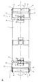
図1、図2は、本実施例のベルトコンベアの全体構成を示すもので、図1はその平面図、図2は側面図である。
ステンレスや繊維強化型の合成樹脂等で形成されるエンドレスのベルト1は、左右両端のプーリーローラ2、3、ベルトコンベアの基台4の底面両端に取り付けられたガイドローラ5、6及び基台4の底面中央に設けられた駆動プーリーローラ7に掛け渡されており、この駆動プーリーローラ7を、基台4に取り付けられた減速機付きモータ8により駆動することにより、ベルト1は、プーリーローラ2、3、ガイドローラ5、6に案内されて、ベルト1上の物品を搬送する。なお、駆動プーリーローラ7は、図示しないハンドルなどにより、上下に移動できるようになっており、ベルトテンションを調節することができる。
[Example 1]
1 and 2 show the overall configuration of the belt conveyor of the present embodiment. FIG. 1 is a plan view thereof, and FIG. 2 is a side view thereof.
The
この駆動プーリーローラ7の左右上方には、ベルト1を駆動プーリーローラ7に確実に係合させるための補助プーリーローラ8、9が設けられ、これらの補助プーリーローラ8、9は、図3に示されるように、球面滑りによりその中央部をシャフトに揺動自在に支持させた、前記特許文献4、5に示されているような自動調芯型のものを採用することが好ましい。
なお、搬送物品は、プーリーローラ2、3間のベルト1上面で搬送されるが、物品がエンドレスベルト1の左右にずれて載置されたり、また、物品をエンドレスベルト1から両サイドに振り分ける際に、ベルト1の上面に作用する物品の荷重が幅方向に大きく変化するので、これがベルト1を蛇行させる大きな要因となるが、基台4の下側ではこうした搬送物品の荷重変化の影響が少ないので、上述したプーリーローラ内部の球面滑りを用いた自動調芯装置により十分に惰行を防止できる。
The conveyed article is conveyed on the upper surface of the
このプーリーローラ2、3の両端には、ベルトの離脱を防止するための接触部として、フランジ10が設けられており、このフランジ10から突出する回転軸11(図1参照)は、左右のアーム12、13の端部に回転自在に支持されており、これらのアーム12、13の他端は、揺動アーム14にボルト等により固着されており、この実施例では、左右のアーム12、13と揺動アーム14とからなるコの字状のプーリーローラ支持装置15を構成している。
A
このプーリーローラ支持装置15は、図4に示されるように、プーリーローラ2、3の回転軸11の中心線CL1上において、その長さ方向の中心点Oを基準点としてこれを不動にした上で、この中心点Oから、中心線CL1の回転軸11両端部間の線分に対する直角2等分線CL2を中心軸として、プーリーローラ2、3を、中心点Oを含む垂直面内においてA−B方向に揺動可能にするとともに、中心点Oを含む水平面内において、プーリーローラ2、3を、中心点Oを通る垂直中心線CL3を中心として、C−D方向に揺動可能に支持する。
As shown in FIG. 4, the pulley
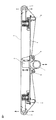
すなわち、揺動アーム14の中央部には、前述の直角2等分線CL2を中心とする円形の開口が内周側壁(プーリーローラ2側)及び外周側壁(反プーリーローラ2側)の双方に形成されている。
一方、基盤16に立設されたフランジ17間にも、直角2等分線CL2を中心軸とし、揺動アーム14の中央部に形成された開口とほぼ同一の径を有する支軸18が設けられており、揺動アーム13を両フランジ17間に配置し、支軸18を一方のフランジ17の開口から、揺動アーム14の中央部の両開口を通し、他方のフランジ17の開口に挿通することにより、これを軸受部として、揺動アーム13は、直角2等分線CL2を中心軸として、図4のA−B方向に、アーム12、13が基台4のいずれかの箇所に接触する角度範囲内で揺動できるようになっている。なお、支軸18は、ボールベアリング等の回転軸受を介して、揺動アーム14の中央部に形成された開口に支持され、コの字型のプーリーローラ支持装置15がスムースに揺動できるようになっている。
That is, in the central portion of the
On the other hand, between the flanges 17 erected on the
基盤16は、プーリーローラ2の中心点Oを中心として、内側に小径の円弧に沿う内周側面161と外側に大径の円弧に沿う外周側面162を備えており(図1参照)、図4に示されるように、内周側161面寄りに中心点Oを中心とする半径R1の溝163、164、そして外周側面162寄りに中心点Oを中心とする半径R2の溝165、166が表裏両面に形成されている。
一方基台4には、基盤16をスライド可能に支持するスライダーブラケットベース19が取り付けられており、基盤16の内周側面161に対向するよう、わずかに径の小さい円弧状の対向周面を備えたブラケットスペーサ20を介して、スライダー圧力座金21が基盤16の内周側上面を覆うように取り付けられている。
The
On the other hand, a
スライダーブラケットベース19の上面及びスライダー圧力座金21の下面には、基盤16の内周側面161寄りに表裏に形成された半径R1の溝163、164のそれぞれに対向するよう、半径R1の溝191、211が形成され、対向する溝163−191間及び溝164−211間のそれぞれに、半径R1の曲率を有するスチールボールスペーサ22が、スライダーブラケットベース19の上面側及びスライダー圧力座金21の下面に固定されている。
On the upper surface of the
基盤16の外周側面162側も同様の構造をしており、スライダーブラケットベース19には、基盤16の外周側面162に対向するよう、わずかに径の大きい円弧状の対向周面を備えたブラケットスペーサ23を介して、スライダー圧力座金24が基盤16の外周側上面を覆うように取り付けられている。
The outer
スライダーブラケットベース19の上面及びスライダー圧力座金24の下面には、基盤16の外周側面162(図1参照)寄りに表裏両面に形成された、半径R2の溝165、166のそれぞれに対向するよう、半径R2の溝192、241が形成され、対向する溝165−192間及び溝166−241間のそれぞれに、半径R2の曲率を有するスチールボールスペーサ22が、スライダーブラケットベース19の上面側及びスライダー圧力座金24の下面に固定されている。
The upper surface of the
なお、ブラケットスペーサ20、23の基盤16の内周側面161、外周側面162に対向する周面は、プーリーローラ2、3の中心点Oを中心とした円弧とするが、基盤16が、中心点Oを中心として、がたつくことなく、しかもスチールボールスペーサ22によりスムースに円弧軌跡を描いてスライドできるよう、前述のように、ブラケットスペーサ20の周面は、基盤16の内周側面161の半径よりわずかに小さく、また、また、ブラケットスペーサ23の周面は、基盤16の外周側面162の半径よりわずかに大きくして、最小限の遊びを設けている。
The peripheral surfaces of the
この実施例では、スチールボールスペーサ22を使用したが、図5に示されるようなニードルスラストベアリングを使用してもよい、このときは、基盤16の表裏面、スライダーブラケットベース19の上面、スライダー圧力座金21、24の下面に形成される溝形状を、ニードルスラストベアリングに合わせてコの字状の溝とすればよい。
なお、基盤16、スライダーブラケットベース19、ブラケットスペーサ20、23、スライダー圧力座金21、24の加工精度を高めれば、スチールボールスペーサ22やニードルスラストベアリングを使用しなくても、潤滑油を介在させるだけで、基盤16の円滑なスライドを実現できる。
In this embodiment, the
If the processing accuracy of the
さらに、この実施例では、スライダーブラケットベース19、ブラケットスペーサ20、23、スライダー圧力座金21、24やスチールボールスペーサ22等を介して、基盤16を、プーリーローラ2、3の軸方向に延びる中心軸の長さ方向中心点Oを中心とした円弧軌跡上にスライド可能としたが、図6、図7にみられるように、基盤16の下面に設けた、V溝を有するホイール25、26(図6では図示省略)、27、28と、基台4に設けた、円弧状のV型レール29(内周側)、30(外周側)を有するレール盤31により、プーリーローラ2、3の軸方向に延びる中心軸の長さ方向中心点Oを中心とした円弧上をスライドできるようにしてもよい。
Furthermore, in this embodiment, the
すなわち、基盤16の下面には、内周側に中心点Oから半径R3の箇所にホイール25、26が、そして、外周側に、中心点Oから半径R4の箇所に2個のホイール27、28が設けられており、各ホイール25ないし28は、中央にV溝(この実施例では直角溝)を備えている。
一方、基台4の上面には、内周側及び外周側に、中心点Oを中心とする大小の円弧を描くV型レール29、30を備えたレール盤31が固着されており、V型レール29、30のそれぞれに、ホイール25、26及びホイール27、28が、図7に示されるように互いに嵌合し、基盤16の中心点Oを中心とする円弧状のスライドを可能にしている。
That is, on the lower surface of the
On the other hand, on the upper surface of the
[実施例2]
実施例1では、ベルト1が蛇行しようとすると、ベルト1の端部がプーリーローラ2、3の両端に設けられたフランジ10に接触することにより当接圧が作用し、この当接圧を解消する方向に基盤16がスライドし、また、揺動アーム14を揺動させる。すわなち、フランジ10との接触により、ベルト1に作用する当接圧が、ベルト1を中心方向に復帰させて調芯を行う復元力として作用し、上述のように効果的な自動調芯を実現できる。
[Example 2]
In the first embodiment, when the
ところで、ベルト1として合成樹脂製のものを使用する場合、こうした樹脂ベルトには、様々な仕様があり、例えば、ガラス繊維で強化したポリウレタン樹脂、フッ素樹脂の心体裏面にポリウレタン含浸導電帆布を積層したもの等が使用されている。
樹脂ベルトの材質、厚さに応じて、使用し得るプーリーローラ径の最小半径が定められており、例えば、ガラス繊維で強化したポリウレタン樹脂の裏面に、ポリウレタン含浸導電帆布を積層した樹脂のベルトの場合、厚さ0.5mmの心体を2層使用した強化型のものでは最小半径50mm、厚さ0.5mmの心体を1層使用した薄型のものでは、最小半径が20mmと定められている。
By the way, when using a
The minimum radius of pulley roller diameter that can be used is determined according to the material and thickness of the resin belt. For example, a resin belt in which polyurethane impregnated conductive canvas is laminated on the back surface of polyurethane resin reinforced with glass fiber. In the case of a reinforced type using two layers of a core body having a thickness of 0.5 mm, the minimum radius is set to 50 mm, and in a thin type using one layer of a core body having a thickness of 0.5 mm, the minimum radius is set to 20 mm. Yes.
したがって、ベルト1として強化型ベルトを使用した場合、プーリーローラ2、3のドラム径は半径50mm以上とすることになるが、この半径であれば、ベルト1が蛇行した際、その端部とフランジ10との接触範囲を十分に確保することができ、ベルト1を中心方向に引き戻して調芯を行うのに十分な復元力を発生させることができる。
しかし、より小さな搬送物品のコンベアベルト間の円滑な乗り移りを実現するため、ベルト1として薄型ベルトを使用することにより、プーリーローラ2、3のドラム径を20mm程度まで小さくして、実験を行ったところ、運転をしばらく継続させると、ベルト1の端部がフランジ10に乗り上げてしまい、最終的にはベルト1が脱輪してしまうトラブルが頻繁に発生した。
これは、プーリーローラ2、3のドラム径が20mm程度まで小径化したため、ベルト1とフランジ部10の接触範囲(接触長さ及び接触面積)が非常に小さくなり、さらに、ベルト1の端部の1点が、フランジ部10に接触してから離れるまでの時間が非常に短くなるため、ベルト1の蛇行により、プーリーローラ2、3上で、スラスト方向に移動しようとする力に対し、調芯を行うための十分な復元力を発生させることができないことに起因する。
Therefore, when a reinforced belt is used as the
However, in order to realize a smooth transfer between conveyor belts of smaller transport articles, an experiment was conducted by using a thin belt as the
This is because the pulley diameter of the
そこで、実施例2では、プーリーローラ2、3のドラム径をさらに小径化するため、薄型ベルトを使用した場合でも、ベルト調芯を行うための十分な復元力を発生させるための接触部として、フランジ10に換え、図8に示されるように、両端にナイロン樹脂等の自己潤滑性のある樹脂で形成された案内ブロック32を採用した。以下、実施例2について詳述する。
Therefore, in Example 2, in order to further reduce the drum diameter of the
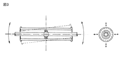
この実施例では、ベルト1として、現在市販されている樹脂製ベルトのうち、許容し得るプーリーローラ半径が最小の5mmである薄型ベルトを使用し、これに伴い、プーリーローラ2、3として、ドラム直径が13mm、両端に突出する回転軸11の直径が5mmのものを使用した。プーリーローラ2、3は、同一の構造であるため、以下、プーリーローラ2側の構造について説明する。
図9に示されるように、回転軸11は、プーリーローラ2の両端から突出し、ナイロン樹脂製案内ブロック32の内側面32−1に設けられた軸受孔に回転自在に支持されている。したがって、プーリーローラ2の長さは、実施例1のものと比較して、両端のナイロン樹脂製案内ブロック32の軸方向長さ分だけ短くなっている。
In this embodiment, a thin belt having a minimum allowable pulley roller radius of 5 mm is used as the
As shown in FIG. 9, the rotating
案内ブロック32の内側面32−1は、プーリーローラ2の回転軸11に対し略垂直で、プーリーローラ2の外端面に対し微少間隙を介して対向している。
案内ブロック32を軸方向からみたとき、図10にみられるように、角部が円弧状の3角形状をしており、ベルト1の搬送面、すなわち揺動アーム14に対し略平行な面32−2と、基台4の底面に設けられたガイドローラ5、6に向かうベルト1の面に対し略平行な面32−3と、揺動アーム14に略垂直に対向する面32−4と、面32−2と32−3間を接続する円弧状の面32−5を備えている。なお、面32−2と面32−3とを接続する円弧状の面32−5は、プーリーローラ2の軸方向でみたとき、プーリーローラ2と同一の中心点を有しており、その直径もドラム径とほぼ同一に設定されている。
したがって、ベルト1の両端部は、搬送面と平行な面32−2からプーリーローラ2の上端に案内され、このベルト1が、プーリーローラ2の外周に巻き掛けられて屈曲する際、プーリーローラ2の軸方向からみて、面32−2と面32−3とを接続する円弧状の面32−5が、プーリーローラ2の外表面のうち、ベルト1が巻き掛けられて接触する外表面と均一な表面を形成するようになっている。
The inner side surface 32-1 of the
When the
Therefore, both end portions of the
案内ブロック32は、面32−2が揺動アーム14のアーム12に対し略平行となるよう、その外側面に形成されたネジ孔あるいは埋め込みナットにより、アーム12の端部外方に形成された開口部から挿通される2本のボルト33により取り付けられている。
The
案内ブロック32の外縁部には、図9に示されるように、面32−2、32−5、32−3に対し、ベルト1の厚さより若干高い段差部32−6が形成されている。段差部32−6の内端面は、ベルト1の進行方向(図9下方向)に対し、若干先細状に形成されており、本実施例では、段差部32−6の厚さを、上流端側で9mm、下流端側で10mmとしている。
なお、回転軸11を通る垂直断面でみたとき、段差部32−6の内端面は、各面32−2、32−5、32−3に対し略直角をなしており、その上流端は、垂直方向に半径2mm程度の円弧状に形成され、進行してくるベルト1をスムースに案内できるようになっている。
As shown in FIG. 9, a stepped portion 32-6 that is slightly higher than the thickness of the
When viewed in a vertical cross section passing through the
案内ブロック32の面32−2、32−3の軸方向略中央部から内側端には、図10に示されるように、面32−2のベルト進行方向の略中央部から、それぞれ面32−4に至るまで、凹部32−7、32−8が形成されており、両凹部に、図9に示されるように、例えば、ステンレス等からなるブリッジシャーシ34の両端を嵌入し、案内ブロック32の面32−4の背面をそれぞれボルト35で固定することにより、両案内ブロック32間に掛け渡される。
このようにして、左右一方の案内ブロック32の段差部32−6の内端から他方の案内ブロック32の段差部32−6の内端に至るまで、両端側が案内ブロック32の表面、その間がブリッジシャーシ34の表面よりなる、均一な面が形成されるようになっている。
すなわち、ステンレス製のブリッジシャーシ34の厚さは、凹部32−7、32−8の深さとほぼ等しくなるよう選定されており、両案内ブロック32の面のうち、揺動アーム14に対し略平行な面32−2に形成された凹部32−7に嵌入された部分から、揺動アーム14に略垂直に対向する面32−4を経て、ガイドローラ5、6に向かうベルト1の面に対し略平行な面32−3に形成された凹部32−8の端部に到る。
As shown in FIG. 10, from the substantially central portion of the surface 32-2 in the belt traveling direction to the inner end from the substantially central portion in the axial direction of the surfaces 32-2, 32-3 of the
In this way, from the inner end of the stepped portion 32-6 of one of the left and right guide blocks 32 to the inner end of the stepped portion 32-6 of the
That is, the thickness of the stainless
このため、ステンレス製のブリッジシャーシ34の表面は、案内ブロック32のうち、凹部32−7に嵌入された部分は、この面32−2の両端側とともに均一の面を形成し、ベルト1をプーリーローラ2の外周に向けて案内する案内面を形成している。
同様に、ブリッジシャーシ34のうち、凹部32−8に嵌入された部分は、この面33−3の両端側とともに均一の面を形成し、プーリーローラ2の外周により屈曲した後のベルト1を基台4の底面に設けられたガイドローラ5(図2参照)に向けて案内する案内面を形成している。
For this reason, the surface of the stainless
Similarly, the portion of the
このように、ベルト1の両端部は、案内ブロック32の段差部32−6により案内されながら、面32−2を摺動し、ベルト1の端部間がステンレス製のブリッジシャーシ34の表面に沿って摺動した後、プーリーローラ2に案内される。
そして、ベルト1は、端部を案内ブロック32の段差部32−6のうち、面32−2と面32−3とを接続する円弧状の面32−5に形成された段差部により案内されながら、回転するプーリーローラ2により屈曲される。
その後、ベルト1は、再び、端部が段差部32−6により案内されながら、ナイロン樹脂製案内ブロック32の面32−3を摺動し、端部間がステンレス製のブリッジシャーシ34の下方表面を摺動して、ガイドローラ5に向けて案内される。
なお、両端側の案内ブロック32には自己潤滑性があるため、ベルト1の端部を損傷することはなく、また、ブリッジシャーシ34としては、ステンレス等の金属板表面を研磨したものを使用しているので、この部分での摺動によりベルト1の寿命が劣化することもない。
In this way, both end portions of the
The
Thereafter, the
Since the guide blocks 32 at both ends are self-lubricating, the end of the
次に実施例2の作用を説明する。
ベルト1が蛇行し、スラスト方向に移動すると、ベルト1の端面が、案内ブロック32の段差部32−6の内側面に乗り上げるようとする。しかし、段差部32−6が面32−2、32−5、32−3に沿って形成されているため、プーリーローラ2との接触部と比較して、ベルト1の端面との接触範囲及び接触時間をはるかに長く確保することができ、調芯を行うのに十分な復元力を長時間にわたって発生させることができる。これにより、ベルト1が、段差部32−6の上方に乗り上げるのを確実に防止することができる。
Next, the operation of the second embodiment will be described.
When the
なお、段差部32−6を、前述のように、ベルト1の進行方向に対し、若干先細状に形成すると、搬送面に沿って走行するベルト1は、面32−1の下流端でのスラスト方向の移動が最小限に抑制され、さらにベルト1が蛇行してスラスト方向に移動すると、ベルト1の端面が、段差部32−6の内側面に順次接して、徐々に復元力が増加してゆくので、ベルト1の蛇行をより低減し、しかも、ベルト1の端面の損傷を低減することができる。
また、段差部32−6を、回転軸11を通る垂直断面でみたとき、その内側面が底面に対し、上方に向けて拡開するよう傾斜させると、ベルト1が蛇行してスラスト方向に移動する際、復元力を連続的に増加させることができ、調芯作用をより円滑化するとともに、ベルト1の端面の損傷をさらに防止することができる。
If the stepped portion 32-6 is slightly tapered with respect to the traveling direction of the
Further, when the stepped portion 32-6 is viewed in a vertical cross section passing through the
[実施例3]
前述のように、食品機械に使用する搬送ベルトやコピー機の転写ベルトでは、張力を付加する弾性繊維を含まず、非常に薄いテフロン(登録商標)ベルト等を採用している。
このようなベルトではそもそも面剛性がきわめて小さいため、実施例2の案内ブロック32を使用しても、蛇行して乗り上げ、最終的に脱輪を引き起こす可能性がある。
そこで、この実施例では、図11に示すように、プーリーローラ2の回転軸11の両端に圧入スリーブ式の端末キャップ36を嵌着し、この端末キャップ36に、プーリーローラ2のドラム表面との間できわめてベルト両端上部を覆うようなL型のカバーリング36−1を設けた。
[Example 3]
As described above, the transport belt used in the food machine and the transfer belt of the copier employ a very thin Teflon (registered trademark) belt that does not include elastic fibers that apply tension.
In the first place, such a belt has extremely small surface rigidity. Therefore, even if the
Therefore, in this embodiment, as shown in FIG. 11, press-fit sleeve type terminal caps 36 are fitted to both ends of the
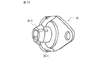
端末キャップ36は、プーリーローラ2の回転軸11の中空部内に挿入され、しかもその回転を阻害しないよう、中空部内に形成された凹部と嵌合する爪部を備えた圧入部36−2を備えた端末キャップ36を押し込むことにより、回転軸11の回転を確保しながら強固に連結される。なお、図12は、端末キャップ36の全体図を示している。
また、カバーリング36−1は、図11、及びそのA−A’断面を矢印方向からみた図13に示されるように、回転軸11の上方中心近傍から、ベルト1の進行方向にプーリーローラ2のドラム表面とベルト1の厚み+0.1mm〜0.2mmの一定の間隙を形成し、回転軸11の下方中心近傍に到るまで形成されている。これにより、プーリーローラ2の略半周にわたり、ドラム表面との間で、カバーリング36−1の下面がベルト1の両端部を覆うようになっている。ベルト1の両端部を覆う範囲は、プーリーローラ2の周方向に可能な限り広範囲とすることが好ましいが、ベルト1の材質や厚みに応じて、半周に到らないものでも有効である。
なお、この実施例では、ベルト1の両端部を覆う範囲がほぼ半周にわたっているため、ベルト1はほぼ水平にプーリーローラ2の下方中心近傍から送られることになるが、その直上流に案内プーリーを設け、基台4の下方に設けられたガイドローラ5、6に向けて案内するようにすればよい。
The
Further, as shown in FIG. 11 and FIG. 13 in which the AA ′ cross section is viewed from the direction of the arrow, the cover ring 36-1 has a
In this embodiment, since the range covering the both ends of the
なお、ベルト1の進行に伴い、回転軸11の内周面が圧入部36−2の外周面に接触したとき、端末キャップ36を同方向に回転させる力が作用するが、図13に示されるように、端末キャップ36のベルト進行方向上流側の端部と基台4との間に、基盤16のスライド、揺動アーム14の揺動を阻害しない程度の小さなバネ定数を有するスプリングやゴム等の弾性部材37が連結されている。これにより、端末キャップ36の回転方向の位置をほぼ一定に維持しつつ、回転軸11のスムースな回転が可能になる。
なお、端末キャップ36は、案内ブロック32と同様、ナイロン等の自己潤滑性の高い樹脂で一体成型するのが好ましいが、他の樹脂や金属素材の表面を、テフロン(登録商標)でコーティングしたものでもよい。これは、案内ブロック32についても同様である。
In addition, when the inner peripheral surface of the
As with the
以上の実施例では、基盤16の下面に、内周側及び外周側にそれぞれ2個のホイールを設けたが、ホイールの数は、それぞれ1個でもよいし、2個以上設けてもよい。
また、上記実施例では、プーリーローラを水平面内及び垂直面内での揺動を可能にしているが、コンベアベルトの形式や配置に応じて、揺動面を適宜傾斜させることも可能である。
In the above embodiment, two wheels are provided on the lower surface of the base 16 on the inner peripheral side and the outer peripheral side, respectively, but the number of wheels may be one or two or more.
In the above embodiment, the pulley roller can be swung in a horizontal plane and a vertical plane. However, the swinging surface can be appropriately tilted according to the type and arrangement of the conveyor belt.
さらに、基台4の底面中央に設けられた駆動プーリーローラ7についても、本実施例と同様の構造とし、例えば、左右のアーム12、13のそれぞれに、小型モータを使用した減速機付きモータを取り付け、ベルト等を介して駆動プーリーローラ7の両端に駆動力を伝達するようにしてもよい。ただし、その際は、揺動アーム13が、支軸18に対して平行を維持するよう、左右のバランスを確保することが必要である。
Further, the drive pulley roller 7 provided at the center of the bottom surface of the
そのほか、基盤16のスムースな揺動を実現するため、空気圧や磁気により浮上させるなど、さまざまな変形が可能である。
In addition, in order to realize smooth swinging of the
以上説明したように、本発明によれば、ドラム内に球面滑り軸受を設ける必要はなく、ドラム径の小さいプーリーローラを使用して幅の広いベルトでも非常に高い剛性を確保した上で、ベルトの惰行を効果的に抑制し、搬送精度の向上、ベルト搬送装置の高寿命化、メンテナンスフリー化を実現することができ、しかもプーリーローラの小径化により、小さな搬送物品であってもベルト間で確実な受け渡しが可能となるので、各種組立ライン、半導体製造ライン、食品製造ラインで使用されるさまざまなベルト搬送装置に広く適用されることが期待できる。 As described above, according to the present invention, it is not necessary to provide a spherical plain bearing in the drum, and even after using a pulley roller with a small drum diameter to secure very high rigidity even with a wide belt, This effectively suppresses the coasting of the belt, improves the conveyance accuracy, extends the life of the belt conveyance device, and makes it maintenance-free. Since reliable delivery is possible, it can be expected to be widely applied to various belt conveying devices used in various assembly lines, semiconductor production lines, and food production lines.
1 エンドレスのベルト
2、3 プーリーローラ
4 基台
5、6 ガイドローラ
7 駆動プーリーローラ
10 フランジ
11 プーリーローラの回転軸
12、13 左右アーム
14 揺動アーム
15 コの字状プーリーローラ支持装置
16 基盤
17 フランジ
18 支軸
19 スライダーブラケットベース
20、23 ブラケットスペーサ
21、24 スライダー圧力座金
22 スチールボールスペーサ
25〜28 ホイール
29、30 V型レール
31 レール盤
32 ナイロン樹脂製の案内ブロック
34 ブリッジシャーシ
36 端末キャップ
37 弾性部材
DESCRIPTION OF
Claims (7)
前記プーリーローラは、両端部に前記ベルトの端面に対向し、前記ベルトが蛇行したときに接触して調芯を行うための復元力を発生する接触部を備えており、かつ、該接触部から突出する回転軸の両端を回転自在に支持する2本のアームと、これらのアームを両端に固着した揺動アームとからなる支持装置により支持されており、
前記揺動アームを、前記プーリーローラ両端部間の中心線(CL1)に対し垂直方向に延びる垂直2等分線(CL2)を中心軸として回転自在に支持する軸受部を備えた基盤と、
該基盤上における前記垂直2等分線上(CL2)の1点を、前記プーリーローラの中心線上にある幅方向中心点(O)を不動の中心とした円弧上を回動させるスライド支持機構とを備えたことを特徴とするベルト搬送装置。 In a belt conveyance device having an endless belt that is stretched between pulley rollers at both ends,
The pulley roller is provided with a contact portion that faces the end face of the belt at both ends, and generates a restoring force for contact and alignment when the belt meanders, and from the contact portion It is supported by a support device composed of two arms that rotatably support both ends of the protruding rotating shaft, and a swing arm that fixes these arms to both ends.
A base including a bearing portion that rotatably supports the swing arm with a vertical bisector (CL2) extending in a direction perpendicular to a center line (CL1) between both ends of the pulley roller as a central axis;
A slide support mechanism for rotating one point on the vertical bisector (CL2) on the base on an arc whose center in the width direction (O) on the center line of the pulley roller is stationary. A belt conveying device comprising:
Priority Applications (1)
| Application Number | Priority Date | Filing Date | Title |
|---|---|---|---|
| JP2011205867A JP5879080B2 (en) | 2010-09-30 | 2011-09-21 | Belt conveying device with self-aligning pulley roller |
Applications Claiming Priority (3)
| Application Number | Priority Date | Filing Date | Title |
|---|---|---|---|
| JP2010220757 | 2010-09-30 | ||
| JP2010220757 | 2010-09-30 | ||
| JP2011205867A JP5879080B2 (en) | 2010-09-30 | 2011-09-21 | Belt conveying device with self-aligning pulley roller |
Publications (2)
| Publication Number | Publication Date |
|---|---|
| JP2012091933A JP2012091933A (en) | 2012-05-17 |
| JP5879080B2 true JP5879080B2 (en) | 2016-03-08 |
Family
ID=46385764
Family Applications (1)
| Application Number | Title | Priority Date | Filing Date |
|---|---|---|---|
| JP2011205867A Active JP5879080B2 (en) | 2010-09-30 | 2011-09-21 | Belt conveying device with self-aligning pulley roller |
Country Status (1)
| Country | Link |
|---|---|
| JP (1) | JP5879080B2 (en) |
Families Citing this family (2)
| Publication number | Priority date | Publication date | Assignee | Title |
|---|---|---|---|---|
| JP6785147B2 (en) * | 2016-12-19 | 2020-11-18 | オークラ輸送機株式会社 | Transport device |
| CN116995884B (en) * | 2023-09-27 | 2023-12-29 | 无锡星微科技有限公司杭州分公司 | Direct-drive high-dynamic-performance movement device and control method |
Family Cites Families (5)
| Publication number | Priority date | Publication date | Assignee | Title |
|---|---|---|---|---|
| JPH0170707U (en) * | 1987-10-30 | 1989-05-11 | ||
| JPH03130245U (en) * | 1990-04-13 | 1991-12-27 | ||
| JP3243984B2 (en) * | 1994-11-15 | 2002-01-07 | 富士ゼロックス株式会社 | Belt transport device |
| US5659851A (en) * | 1995-11-17 | 1997-08-19 | Minnesota Mining And Manufacturing Company | Apparatus and method for steering an endless belt |
| US7873311B2 (en) * | 2007-12-05 | 2011-01-18 | Kabushiki Kaisha Toshiba | Belt transfer device for image forming apparatus |
-
2011
- 2011-09-21 JP JP2011205867A patent/JP5879080B2/en active Active
Also Published As
| Publication number | Publication date |
|---|---|
| JP2012091933A (en) | 2012-05-17 |
Similar Documents
| Publication | Publication Date | Title |
|---|---|---|
| KR100301712B1 (en) | A belt driving device having a belt shift correcting member | |
| JPH11106081A (en) | Photosensitive belt skew stopping mechanism for electrophotographic device | |
| JP5879080B2 (en) | Belt conveying device with self-aligning pulley roller | |
| US11072506B2 (en) | Belt driving device with steering roller | |
| US20230115458A1 (en) | Rollerless idler module and vehicle conveyor system having the same | |
| JP6900299B2 (en) | Belt drive device and image forming device | |
| KR101526192B1 (en) | Belt reversing apparatus of belt conveyor | |
| JP5068565B2 (en) | Conveyor automatic alignment device | |
| JP7320643B2 (en) | Curved conveyors, curved belts, and how to install curved belts | |
| CN217024289U (en) | Corner conveying device | |
| JP6584163B2 (en) | Branching device | |
| KR20190047170A (en) | Horizontal Conveyor System Having Both Normal Speed and Double Speed | |
| JP2017173749A (en) | Belt conveying device, fixing device, and image forming apparatus | |
| CN111646187A (en) | Sorting module for balance wheel sorting equipment and balance wheel sorting equipment | |
| JP6126320B1 (en) | Branching device | |
| JP2022035108A (en) | Conveyor transportation auxiliary apparatus and conveyor apparatus | |
| CN212531299U (en) | Sorting module for balance wheel sorting equipment and balance wheel sorting equipment | |
| JP5082659B2 (en) | Conveyor equipment | |
| CN220412315U (en) | Roller structure, conveying line and conveying system | |
| CN220641313U (en) | Sample transmission device | |
| JPH079823U (en) | Chain conveyor drive | |
| JP2872802B2 (en) | Belt drive | |
| JP2021080065A (en) | Automatic centering device of belt conveyor, and belt conveyor | |
| JPH04263251A (en) | Immersion type processing rack | |
| JP3827405B2 (en) | Flat belt meandering prevention device |
Legal Events
| Date | Code | Title | Description |
|---|---|---|---|
| A621 | Written request for application examination |
Free format text: JAPANESE INTERMEDIATE CODE: A621 Effective date: 20140902 |
|
| A977 | Report on retrieval |
Free format text: JAPANESE INTERMEDIATE CODE: A971007 Effective date: 20150521 |
|
| A131 | Notification of reasons for refusal |
Free format text: JAPANESE INTERMEDIATE CODE: A131 Effective date: 20150707 |
|
| A521 | Written amendment |
Free format text: JAPANESE INTERMEDIATE CODE: A523 Effective date: 20150827 |
|
| TRDD | Decision of grant or rejection written | ||
| A01 | Written decision to grant a patent or to grant a registration (utility model) |
Free format text: JAPANESE INTERMEDIATE CODE: A01 Effective date: 20160105 |
|
| A61 | First payment of annual fees (during grant procedure) |
Free format text: JAPANESE INTERMEDIATE CODE: A61 Effective date: 20160201 |
|
| R150 | Certificate of patent or registration of utility model |
Ref document number: 5879080 Country of ref document: JP Free format text: JAPANESE INTERMEDIATE CODE: R150 |
|
| R250 | Receipt of annual fees |
Free format text: JAPANESE INTERMEDIATE CODE: R250 |
|
| R250 | Receipt of annual fees |
Free format text: JAPANESE INTERMEDIATE CODE: R250 |