JP5878814B2 - Optical receiver - Google Patents
Optical receiver Download PDFInfo
- Publication number
- JP5878814B2 JP5878814B2 JP2012096569A JP2012096569A JP5878814B2 JP 5878814 B2 JP5878814 B2 JP 5878814B2 JP 2012096569 A JP2012096569 A JP 2012096569A JP 2012096569 A JP2012096569 A JP 2012096569A JP 5878814 B2 JP5878814 B2 JP 5878814B2
- Authority
- JP
- Japan
- Prior art keywords
- optical
- fiber tray
- fiber
- main body
- body casing
- Prior art date
- Legal status (The legal status is an assumption and is not a legal conclusion. Google has not performed a legal analysis and makes no representation as to the accuracy of the status listed.)
- Active
Links
- 230000003287 optical effect Effects 0.000 title claims description 86
- 239000000835 fiber Substances 0.000 claims description 106
- 239000013307 optical fiber Substances 0.000 claims description 29
- 230000003321 amplification Effects 0.000 claims description 22
- 238000003199 nucleic acid amplification method Methods 0.000 claims description 22
- 238000003780 insertion Methods 0.000 description 4
- 230000037431 insertion Effects 0.000 description 4
- 238000009434 installation Methods 0.000 description 4
- 238000004804 winding Methods 0.000 description 3
- 238000000034 method Methods 0.000 description 2
- 239000011347 resin Substances 0.000 description 2
- 229920005989 resin Polymers 0.000 description 2
- 238000004891 communication Methods 0.000 description 1
- 230000007423 decrease Effects 0.000 description 1
- 238000012986 modification Methods 0.000 description 1
- 230000004048 modification Effects 0.000 description 1
- 238000012544 monitoring process Methods 0.000 description 1
- 238000000465 moulding Methods 0.000 description 1
- XLYOFNOQVPJJNP-UHFFFAOYSA-N water Substances O XLYOFNOQVPJJNP-UHFFFAOYSA-N 0.000 description 1
Images


Description
本発明は、光受信機に関するものである。 The present invention relates to an optical receiver.
屋外からの光ファイバを屋内に引き込むための装置として、光受信機(FTTH端末機)が知られている(例えば特許文献1参照)。この光受信機は、放送系の光ファイバにて入力される光信号を、光受信増幅部にて電気信号に変換し増幅して出力するものである。 An optical receiver (FTTH terminal) is known as a device for drawing an optical fiber from the outside indoors (see, for example, Patent Document 1). In this optical receiver, an optical signal input through a broadcast optical fiber is converted into an electric signal by an optical reception amplification unit, amplified, and output.
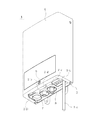
このような光受信機101は、通常、設置された状態において、図19(a)に示すように、内蔵される電源ユニット102(図19(b)参照)の電源コード102aが電源コンセント(図示せず)に接続され、光ケーブル103(光ファイバーケーブル)を通じて光信号が入力され、同軸ケーブル104を通じてテレビ放送信号が出力されるようになっている。
When such an
しかしながら、実際に設置場所で光受信機を設置する場合に、設定場所によっては電源コンセントが設置場所近くにないため、例えば図19(b)に示すように、本体ケーシング101A内から電源ユニット102を取り出して、屋内の電源コンセント(図示せず)に電源コード102aを接続できる場所に電源ユニット102を配置する一方、電源ユニット102と、本体ケーシング101A内の光受信増幅ユニット(図示せず)とを同軸ケーブル104で接続して同軸ケーブル104を介して電力を供給するようにし、電源ユニット102から別の同軸ケーブル105を通じてテレビ放送信号がテレビ受像機などに供給するようにして使用する場合がある。
However, when the optical receiver is actually installed at the installation location, depending on the setting location, there is no power outlet near the installation location. For example, as shown in FIG. The
そのような場合、本体ケーシング101Aの開口部を開放し、電源ユニット102を取り出す必要があるが、本体ケーシング101Aの開口部にはファイバトレイ(図示せず)は取り外し可能に嵌め込まれているので、ファイバトレイを本体ケーシング101Aより完全に外し、ファイバトレイを作業者が持って、電源ユニット102の取り外し作業をしなければならず、作業性が悪かった。特に、そのような光受信機101は、通常、高所に設置され、脚立の上などにのって作業を行う必要があるので、電源ユニット102の取り出しを容易に行えることが望まれている。
In such a case, it is necessary to open the opening of the main body casing 101A and take out the
ところで、光ファイバ収納ケースを箱体に回転可能に取り付けたものが知られている(例えば特許文献2参照)。 By the way, what attached the optical fiber storage case to the box so that rotation was possible is known (for example, refer patent document 2).
特許文献2に記載の光ファイバ収納ケースは、光ファイバが収納された部分が箱体内部に向けて位置し、箱体内の表示板をケースカバーとしてするものであり、光ファイバトレイに光ファイバが巻き付けられた部分が本体ケーシング外部に向けて設けられる構造の光受信機とは基本となる構造が異なり、そのまま適用することができない。
The optical fiber storage case described in
つまり、特許文献2記載の技術は、ファイバ収納ケースの回転軸が水平方向であり、下方に回転して開放した状態で、光ファイバを巻き付けることで光ファイバの収納操作を容易にすることを開示するにすぎない。
That is, the technique described in
本発明は、本体ケーシングからの電源ユニットの取り出しを容易に行うことができる光受信機を提供することを目的とする。 An object of the present invention is to provide an optical receiver capable of easily taking out a power supply unit from a main casing.
請求項1の発明は、一面が開放された開口部となっている本体ケーシングと、前記本体ケーシングに第1回転軸回りに回転可能に設けられ前記開口部を開閉可能に閉じるケーシングカバーとを有し、前記本体ケーシングの内部に電源ユニットと光信号を電気信号に変換して増幅する光受信増幅ユニットとを設け、前記一面側に、前記開口部とほぼ同じ大きさのファイバトレイを設け、前記ファイバトレイに光ファイバの余長部分を巻き付けて収納すると共に、前記光受信増幅ユニットの光中継用アダプタに前記光ファイバの端部の光コネクタを前記ファイバトレイの開口を通じて接続している光受信機において、前記ファイバトレイは、前記本体ケーシングに前記第1回転軸に直交する第2回転軸回りに回転可能に取り付けられ、前記第2回転軸回りに回転させることで前記開口部を開閉する構成とされ、前記ファイバトレイを開いた状態で、前記電源ユニット又は前記光受信増幅ユニットの少なくとも一方を前記本体ケーシング内から取り出し可能であり、前記ファイバトレイと前記本体ケーシングとの間には、前記ファイバトレイの開状態を弾性的に保持する保持手段が設けられ、前記保持手段が、前記ファイバトレイの外側部に基端部が結合され前記ファイバトレイの前記外側部と平行に延びるように設けられる弾性片と、前記弾性片に設けられる突起部と、前記本体ケーシングの内面側に形成され前記ファイバが前記開口部を開放しているときに、前記突起部が係脱可能に係合し前記ファイバトレイの開状態を弾性的に保持する凹部とを備えることを特徴とする。
The invention according to
このようにすれば、ファイバトレイが本体ケーシングに回転可能に取り付けられているので、本体ケーシング内から電源ユニット又は光受信増幅ユニットを取り出す際に、作業者がファイバトレイを片手で把持しながら作業を行う必要がなくなり、前記電源ユニット又は光受信増幅ユニットを取り出す作業を容易に行うことができる。 In this way, since the fiber tray is rotatably attached to the main body casing, when taking out the power supply unit or the optical receiving amplification unit from the main body casing, the operator can work while holding the fiber tray with one hand. There is no need to carry out, and the work of taking out the power supply unit or the optical reception amplification unit can be easily performed.
また、保持手段によって前記ファイバトレイの開状態が弾性的に保持されるので、電源ユニット又は光受信増幅ユニットの取り出しがより容易となる。 Moreover, since the open state of the fiber tray is elastically held by the holding means, it becomes easier to take out the power supply unit or the optical reception amplification unit .
請求項2に記載のように、前記ファイバトレイは、前記回転可能に取り付けられている側に、前記光ファイバの導入部を有する一方、前記回転可能に取り付けられている側とは反対側において、前記ファイバトレイと前記本体ケーシングとの間に前記ファイバトレイを前記本体ケーシングに係脱可能に係止する係止手段が設けられている、構成とすることができる。
The fiber tray according to
このようにすれば、ファイバトレイが係止手段によって本体ケーシングに確実に保持され、ケースカバーを開いた際にファイバトレイが不用意に回転することがなくなる。 In this way, the fiber tray is securely held by the main body casing by the locking means, and the fiber tray does not rotate carelessly when the case cover is opened.
この場合、請求項3に記載のように、前記ファイバトレイは、前記係止手段による係止を解除する方向に前記ファイバトレイを回転させるためのつまみ部を有する、ことが望ましい。
In this case, as described in
このようにすれば、つまみ部を用いることで、係止手段による係止解除を容易に行うことができる。 If it does in this way, the latch release by a latching means can be easily performed by using a knob part.
請求項4に記載のように、前記ケーブル導入部は、挿入される光ケーブルを複数の板状部で挟持する複数の挟持部分と、隣り合う前記挟持部分の間に形成される係合凹部とを有し、蓋部で覆われる構成とされ、前記蓋部に、前記係合凹部に係脱可能に係合する係合凸部と、前記挟持部分に係合し挟持されている光ケーブルを押さえ付ける押さえ部とが形成されている、ことが望ましい。 According to a fourth aspect of the present invention, the cable introducing portion includes a plurality of sandwiching portions that sandwich the inserted optical cable with a plurality of plate-shaped portions, and an engagement recess formed between the adjacent sandwiching portions. The cover is covered with a cover, and the cover is pressed against an engagement protrusion that is detachably engaged with the engagement recess, and an optical cable that is engaged with and held by the holding portion. It is desirable that a pressing portion is formed.
このようにすれば、蓋部材によって光ケーブルの導入部分の保持を確実に行うことができる。また、挟持部分を、複数の板状部で構成しているので、光ケーブルを挟持しない場合でも、ケーブル導入部からの水の浸入を防止する上で有利である。 If it does in this way, the introduction part of an optical cable can be certainly held by a lid member. Further, since the sandwiching portion is composed of a plurality of plate-like portions, it is advantageous in preventing water from entering from the cable introduction portion even when the optical cable is not sandwiched.
本発明は、ファイバトレイが本体ケーシングに回転可能に取り付けられ、前記ファイバトレイと前記本体ケーシングとの間に前記ファイバトレイの開状態を弾性的に保持する保持手段が設けられているので、本体ケーシング内から電源ユニット又は光受信増幅ユニットを取り出す際に、作業者がファイバトレイを手で把持しながら作業を行う必要がなくなり、前記電源ユニット又は光受信増幅ユニットを取り出す作業を容易に行うことができる。 In the present invention, the fiber tray is rotatably attached to the main body casing, and the holding means for elastically holding the open state of the fiber tray is provided between the fiber tray and the main body casing. When taking out the power supply unit or the optical reception amplification unit from the inside, it is not necessary for the operator to work while holding the fiber tray by hand, and the operation for taking out the power supply unit or the optical reception amplification unit can be easily performed. .
以下、本発明の実施の形態を図面に沿って説明する。なお、以下の説明において、図1〜図3に示すように、光受信機1において、ケーシングカバー4が設けられている側を前側、ケーシングカバー4の回転軸S1がある側を上側、ファイバトレイ3の回転軸S2がある側を左側とする。
Hereinafter, embodiments of the present invention will be described with reference to the drawings. In the following description, as shown in FIGS. 1 to 3, in the
図1〜図3に示すように、光受信機1は、一面(前面)が開放された開口部2aとなっている矩形箱形状の本体ケーシング2と、本体ケーシング2の前面に設けられているファイバトレイ3と、本体ケーシング2の上部に水平方向の回転軸S1(第1回転軸)回りに回転可能に設けられ開口部2aを開閉可能に閉じるケーシングカバー4とを有する。
As shown in FIGS. 1 to 3, the
本体ケーシング2の内部には、図4に示すように、電源ユニット5と光受信増幅ユニット6とが上下に並んで設けられている。光受信増幅ユニット6は、この光受信増幅ユニット6に光信号を受光するための光中継用アダプタ6aを有し、この光中継用アダプタ6aは、シールドケース6bの上面に、支持部材6cを介して一定の角度をなすように取り付けられている。光中継用アダプタ6aを介して入力された光信号は、光受信増幅ユニット6において電気信号に変換され、増幅される。この増幅された電気信号は、シールドケース6bの下面部に設けられた出力端子8から出力される。この出力端子8から出力される電気信号をモニタするモニタ端子7が、シールドケース6bの下面部に出力端子8と並列に設けられている。なお、電気信号はテレビ放送信号であり、この電気信号は出力端子8から同軸ケーブル(図示せず)を介してテレビ受信機などに供給される。
Inside the
本体ケーシング2の下面には、モニタ端子7及び出力端子8がそれぞれ貫通される挿通孔2b,2cが形成されている。また、ケーシングカバー4を本体ケーシング2に固着するためのネジ9が螺着される雌ネジ部2dが下面部側に設けられている。
On the lower surface of the
ケーシングカバー4は、水平方向の回転軸S1回りに回転することで開閉可能とされ、本体ケーシング2との間にそれらをほぼ90°の角度をなした状態で保持する第1保持手段M1が設けられている。この第1保持手段M1は、図5(a)に示すように、ネジ9が設けられている側とは反対側に位置するケーシングカバー4の係止縁部4aと、本体ケーシング2の背面に設けられ係止縁部4aが係脱可能に弾性係合する係止凸部2eとによって構成される。
The
ファイバトレイ3は、本体ケーシング3に対し鉛直方向の回転軸S2(第2回転軸)回りに回転可能に取り付けられ、図4及び図6(a)(b)に示すように、回転軸S2回りに回転することで開口部2aを開閉する構成とされている。
The
このファイバトレイ3は、開口部3aとほぼ同じ大きさで、図7にも示すように、光ケーブルが導入される光ケーブル導入部3Aを有し、導入される光ケーブルの、放送系の光ファイバと通信系の光ファイバの余長部分を巻き付けて収納するものである。この光ケーブル導入部3Aがある側において、本体ケーシング2にファイバトレイ3が回転可能に支持されている。放送系の光ファイバ11の端部の光コネクタ11a(図5(a)参照)が、ファイバトレイ3の開口3aを通じて光受信増幅ユニット6の光中継用アダプタ6aに接続されている。なお、導入された光ケーブルは、具体的に図示していないが、例えば、ファイバの先端部分だけを簡単にコネクタ加工できる簡易コード化部材を用いて、放送系の光ファイバと通信系の光ファイバとに分けられる。
The
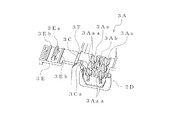
ケーブル導入部3Aは、図8及び図9に詳細を示すように、挿入される光ケーブルを複数の板状部3Aaaで挟持する複数の挟持部分3Aaと、隣り合う挟持部分3Aaの間に形成される係合凹部3Abとを有し、ファイバトレイ3に樹脂ヒンジ3F(弾性ヒンジ)を介して一体に設けられた蓋部3Eで覆われる構成とされている。蓋部3Eに、係合凹部3Abに係脱可能に係合する係合凸部3Eaと、挟持部分3Aaに係合し挟持されている光ケーブル(図示せず)を押さえ付ける押さえ部3Ebとが形成されている。なお、光ケーブル導入部3Aが形成されている側とは反対側には、電源ユニット5から外部に延びる電源コード5aを通す挿通部3Gとが形成されている。
As shown in detail in FIGS. 8 and 9, the
ファイバトレイ3の前面部は、光ケーブルが導入されるケーブル導入部3Aに加えて、ファイバトレイ3の鉛直面部からそれに直交する方向に突出する板状の縦リブを組み合わせることによって、第1巻き付け部3Mと第2巻き付け部3Nとを形成するなどして、光ファイバの余長部分を巻き付けるために通る多彩な通路が形成されている。また、光ファイバが通る部分に対し光ファイバの離脱(浮き上がり)を防止するためのひさし状の水平リブ3fが、通路に向けて水平に突出するように設けられている。
The front portion of the
第1及び第2巻き付け部3M,3Nの間には、それらの間に光ファイバが巻き付けられた場合にその光ファイバより後方位置で、光受信増幅ユニット6の光中継用アダプタ6aに、放送系の光ファイバ11の終端部の光コネクタ11aがファイバトレイ3の開口3aを通じて着脱可能に接続されるようになっている。この開口3aには、開口3aに向かって(底面の)高さが徐々に低くなるように傾斜している案内凹部3dが形成されている(図5(a)参照)。
Between the first and second winding
続いて、ファイバトレイ3を回転可能に支持する構造について説明する。
Then, the structure which supports the
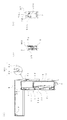
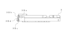
ファイバトレイ3の上部には、図10及び図11(a)に示すように、ファイバトレイ3に基端部が結合され、先端部がファイバトレイ3の上面と平行に延びる片持ちはり状に略L字板状の弾性片3Bが設けられている。この弾性片3Bは、前記基端部から外方に延びる第1部分3Baとこの第1部分3Baの先端部分から後方に延びる第2部分3Bbとを有し、第1部分3Baの先端部(後端部)に回転軸部3Bcが上方に突出するように設けられている。また、第2部分3Bbには、その回転軸部3Bcが設けられている部位から先端に向かって延びる線状の突起部3Bdが形成されている。一方、本体ケーシング2には、図11(b)に示すように、弾性片3Bに対応して突出片部2Aが一体に形成されており、その突出片部2Aに回転軸部3Bcが回転可能に嵌挿される支持穴2Aaが形成されている。また、本体ケーシング2の内面側には、支持穴2Aaから前後方向に延びる溝状の第1凹部2Abと、支持穴2Aaから左右方向に延びる溝状の第2凹部2Acとが形成されている。これにより、本体ケーシング2の開口部2aをファイバトレイ3が閉じているときには、図14(a)〜(d)にケースカバー4を省略して示すようになっている。つまり、図16(c)(e)に示すように回転軸部3Bcが支持穴2Aaに挿通された状態で、図16(b)に示すように突起部3Bdが第1凹部2Abに係脱可能に係合し、ファイバトレイ3の閉状態を弾性的に保持する。一方、ファイバトレイ3が開口部2aを開放しているときには、図15(a)〜(d)にケースカバー4を省略して示すようになっている。つまり、図16(a)示すように回転軸部3Bcが支持穴2Aaに挿通された状態で、図16(d)に示すように、突起部3Bdが第2凹部2Acに係脱可能に係合し、ファイバトレイ3の開状態を弾性的に保持するようになっている。
As shown in FIGS. 10 and 11A, the base end portion is coupled to the
この突起部3Bdと第2凹部2Acとによって、ファイバトレイ3と本体ケーシング2との間に設けられファイバトレイ3を開状態に保持する第2保持手段M2が構成されている(図5(c)及び図6(c)参照)。
The projection 3Bd and the second recess 2Ac constitute second holding means M2 provided between the
また、ファイバトレイ3の下部には、図12(a)(b)に示すように、本体ケーシング2から突出する固定軸部2f(図13参照)に回転可能に係合する逆U形状系の係合部3Cが形成されている。この係合部3Cは、ケーブル導入部3Aに隣接して形成され、切り欠き溝部3Caと、固定軸部2fを回転可能に支持する軸支持部3Cbとを有する。なお、切り欠き溝部3Caは、軸支持部3Cbを成形するに際に成形金型(図示せず)が挿入される部分である。
Further, at the lower part of the
そして、弾性片3Bを弾性変形させて回転軸部3Bcを支持孔2Aaに挿入し、その状態のままファイバトレイ3を後方に移動することで固定軸部2fが軸支持部3Cbに回転可能に支持される。本体ケーシング2の開口部2aをファイバトレイ3が閉じているときの状態を図17(a)(b)に、ファイバトレイ3が開口部2aを開放しているの状態を図17(c)(d)にそれぞれ示す。
Then, the
また、係合部3Cに連続して、本体ケーシング2の、ケーブル導入部3Aが配置される部位に形成される係合凹部2Dに係脱可能に係合する略U字形状の突縁部3Dが後方に突出するように形成されている。ファイバトレイ3が、閉状態にあるとき突縁部3Dが係合凹部2Dに係脱可能に係合することになる。
Further, a substantially U-shaped protruding
このように、ファイバトレイ3が上下部において、両軸部3Bc,2fを利用して本体ケーシング2に回転可能に取り付けられ、ファイバトレイ3を開状態に保持されるようにしているので、ケーシングカバー4を第1保持手段M1にて開状態に保持し、続けてファイバトレイ3を第2保持手段M2にて開状態に保持することで、ファイバトレイ3を本体ケーシング2から取り外すことなく、電源ユニット5を本体ケーシング2内から無理なく取り出すことができる。
As described above, the
さらに、前記回転可能に取り付けられている側(ケーブル導入部3Aがある側)とは反対側においてファイバトレイ3と本体ケーシング2との間にファイバトレイ3を本体ケーシング2に係脱可能に係止する係止手段M3が設けられている。この係止手段M3は、図5(b)に示すように、ファイバトレイ3から後方に突出する弾性係合片3bと、本体ケーシング2から前方に突出し弾性係合片3bに係脱可能に係合して係止する弾性被係合片2gとによって構成される。そして、ファイバトレイ3の、係止手段M3が設けられている部分は、作業者が把持し係止手段M3による係止を解除する方向にファイバトレイ3を回転するためのつまみ部3Hとなっている。
Furthermore, the
上記光受信機によれば、ファイバトレイ3に収納される光ファイバ11の先端に設けた光コネクタ11aを光受信増幅ユニット6の光中継用アダプタ6aに着脱可能に接続することにより、光受信増幅ユニット6に光信号を導入するようにしている。
According to the above optical receiver, the optical connector 11a provided at the tip of the optical fiber 11 accommodated in the
よって、前記背景技術の欄で説明したように、実際に設置場所で光受信機1を設置する際に電源コンセントが設置場所近くにない場合には、ファイバトレイ3が本体ケーシング2に回転可能に取り付けられているので、第1及び第2保持手段によりケーシングカバー2およびファイバトレイ3を開状態に保持し、本体ケーシング2内から電源ユニットを簡単に取り出することができる。これにより、屋内の電源コンセント(図示せず)に電源コードを接続できる場所に電源ユニット5を配置する一方、電源ユニット5と、本体ケーシング2内の光受信増幅ユニット6とを同軸ケーブル(図示せず)で接続して電力を供給するようにし、電源ユニット5から同軸ケーブルを通じてテレビ放送信号がテレビ受像機などに供給するようにして使用することができる。
Therefore, as described in the background section above, when the
この場合、本体ケーシング2内から電源ユニット5を取り出す際に、作業者がファイバトレイ3を片手で把持しながら作業を行う必要がなくなり、電源ユニット5を取り出す作業を容易に行うことができる。
In this case, when taking out the
また、故障などにより電源ユニット5や光受信増幅ユニット6を交換する必要性が生じた場合にも、光中継用アダプタ6aから光コネクタ11aを外すことにより、光ファイバの余長部分を収納したままでファイバトレイ3を回転して開状態に保持することができるので、ファイバトレイ3を本体ケーシング2から取り外すことなく、電源ユニット5や光受信増幅ユニット6を交換のための作業を容易に行うことができる。
Even when the
前記実施の形態では、ファイバトレイ3の開状態あるいは閉状態を維持するために、線状の突起部3Bdと凹部2Ac,2Adとの弾性係合を利用しているが、本発明はそのような弾性係合だけでなく、例えば図18に示すように、山形状の突起部3Bd’と係合穴2Ab’,2Ac’との弾性係合関係で、ファイバトレイ3の開状態あるいは閉状態を維持するように構成することも可能である。
In the above embodiment, in order to maintain the open state or the closed state of the
1 光受信機
2 本体ケーシング
2A 突出片部
2Aa 支持穴
2Ab,2Ab’ 第1凹部
2Ac,2Ac’ 第2凹部
2D 係合凹部
2a 開口部
2b,2c 挿通孔
2d 雌ねじ部
2e 係止凸部
2f 固定軸部
2g 弾性被係合片
3 ファイバトレイ
3A ケーブル導入部
3Aa 挟持部分
3Ab 係合凹部
3B 弾性片
3Ba 第1部分
3Bb 第2部分
3Bc 回転軸部
3Bd,3Bd’ 突起部
3C 係合部
3Ca 切り欠き溝部
3Cb 軸支持部
3D 突縁部
3E 蓋部
3Ea 係合凸部
3Eb 押さえ部
3F 樹脂ヒンジ
3G 挿通部
3H つまみ部
3a 開口
3b 弾性係合片
4 ケーシングカバー
4a 係止縁部
5 電源ユニット
6 光受信増幅ユニット
6a 光中継用アダプタ
6b シールドケース
6c 支持部材
11 光ファイバ
11a 光コネクタ
S1,S2 回転軸
M1,M2 保持手段
M3 係止手段
DESCRIPTION OF
Claims (4)
前記ファイバトレイは、前記本体ケーシングに前記第1回転軸に直交する第2回転軸回りに回転可能に取り付けられ、前記第2回転軸回りに回転させることで前記開口部を開閉する構成とされ、
前記ファイバトレイを開いた状態で、前記電源ユニット又は前記光受信増幅ユニットの少なくとも一方を前記本体ケーシング内から取り出し可能であり、
前記ファイバトレイと前記本体ケーシングとの間には、前記ファイバトレイの開状態を弾性的に保持する保持手段が設けられ、
前記保持手段が、
前記ファイバトレイの外側部に基端部が結合され前記ファイバトレイの前記外側部と平行に延びるように設けられる弾性片と、
前記弾性片に設けられる突起部と、
前記本体ケーシングの内面側に形成され前記ファイバが前記開口部を開放しているときに、前記突起部が係脱可能に係合し前記ファイバトレイの開状態を弾性的に保持する凹部とを備えることを特徴とする光受信機。 A main body casing having an opening with one surface open; and a casing cover that is provided in the main body casing so as to be rotatable about a first rotation axis and closes the opening so as to be openable and closable. A power supply unit and a light receiving and amplifying unit for converting an optical signal into an electric signal and amplifying the optical signal, and a fiber tray having substantially the same size as the opening is provided on the one surface side. In the optical receiver in which the long portion is wound and stored, and the optical connector at the end of the optical fiber is connected to the optical repeater adapter of the optical reception amplification unit through the opening of the fiber tray,
The fiber tray is attached to the main body casing so as to be rotatable around a second rotation axis orthogonal to the first rotation axis, and is configured to open and close the opening by rotating around the second rotation axis.
With open said fiber tray is at least one of the power supply unit or the light receiving amplifying unit removable from the main body casing,
Between the fiber tray and the main body casing, a holding means for elastically holding the open state of the fiber tray is provided,
The holding means is
An elastic piece provided at a base end portion coupled to an outer portion of the fiber tray and extending in parallel with the outer portion of the fiber tray;
A protrusion provided on the elastic piece;
A recess formed on the inner surface side of the main body casing, wherein the protrusion is detachably engaged when the fiber opens the opening, and elastically holds the open state of the fiber tray. An optical receiver characterized by that.
前記蓋部に、前記係合凹部に係脱可能に係合する係合凸部と、前記挟持部分に係合し挟持されている光ファイバを押さえ付ける押さえ部とが形成されている、請求項2または3記載の光受信機。 The introduction portion has a plurality of sandwiching portions for sandwiching an optical fiber to be inserted by a plurality of plate-like portions, and an engaging recess formed between the adjacent sandwiching portions, and is covered with a lid portion. And
The engagement convex portion that is detachably engaged with the engagement concave portion and the pressing portion that presses the optical fiber that is engaged with and held by the holding portion are formed on the lid portion. The optical receiver according to 2 or 3 .
Priority Applications (1)
| Application Number | Priority Date | Filing Date | Title |
|---|---|---|---|
| JP2012096569A JP5878814B2 (en) | 2012-04-20 | 2012-04-20 | Optical receiver |
Applications Claiming Priority (1)
| Application Number | Priority Date | Filing Date | Title |
|---|---|---|---|
| JP2012096569A JP5878814B2 (en) | 2012-04-20 | 2012-04-20 | Optical receiver |
Publications (3)
| Publication Number | Publication Date |
|---|---|
| JP2013225006A JP2013225006A (en) | 2013-10-31 |
| JP2013225006A5 JP2013225006A5 (en) | 2015-05-14 |
| JP5878814B2 true JP5878814B2 (en) | 2016-03-08 |
Family
ID=49595104
Family Applications (1)
| Application Number | Title | Priority Date | Filing Date |
|---|---|---|---|
| JP2012096569A Active JP5878814B2 (en) | 2012-04-20 | 2012-04-20 | Optical receiver |
Country Status (1)
| Country | Link |
|---|---|
| JP (1) | JP5878814B2 (en) |
Family Cites Families (3)
| Publication number | Priority date | Publication date | Assignee | Title |
|---|---|---|---|---|
| JP4414215B2 (en) * | 2003-12-25 | 2010-02-10 | 日本アンテナ株式会社 | Optical terminal device |
| JP4980658B2 (en) * | 2006-06-28 | 2012-07-18 | マスプロ電工株式会社 | Optical receiver |
| JP5104705B2 (en) * | 2008-10-09 | 2012-12-19 | 三菱電機株式会社 | Electronics |
-
2012
- 2012-04-20 JP JP2012096569A patent/JP5878814B2/en active Active
Also Published As
| Publication number | Publication date |
|---|---|
| JP2013225006A (en) | 2013-10-31 |
Similar Documents
| Publication | Publication Date | Title |
|---|---|---|
| JP4414215B2 (en) | Optical terminal device | |
| JP2019131116A (en) | Display holder | |
| JP5878814B2 (en) | Optical receiver | |
| JP2007028544A (en) | Intercom device | |
| JP4133414B2 (en) | Optical termination device | |
| JP4585934B2 (en) | Optical receiver | |
| JP2017157188A (en) | Box body for information distribution board | |
| JP2014120169A (en) | Electronic device | |
| JP2010016253A (en) | Multimedia port and its operation method | |
| JP4283245B2 (en) | Optical receiver unit storage structure | |
| JP6512274B1 (en) | Terminal block and air conditioner | |
| JP6663800B2 (en) | Optical receiver housing | |
| JP5123993B2 (en) | Optical receiver | |
| JP4835564B2 (en) | Information device | |
| JP7404610B2 (en) | Information distribution board | |
| JP5653661B2 (en) | Optical line housing structure | |
| JP4589842B2 (en) | Optical fiber storage case mounting mechanism | |
| JP5653660B2 (en) | Optical line housing structure | |
| JP2017130559A (en) | Information distribution board | |
| US8467652B2 (en) | Glass fiber connection module | |
| JP6124576B2 (en) | Communication line fixing structure | |
| JP4174382B2 (en) | Amplifier case | |
| JP4785632B2 (en) | Device unit attachment / detachment structure for electronic devices | |
| JP6622111B2 (en) | Box for information distribution board | |
| JP2007028541A (en) | Intercom device |
Legal Events
| Date | Code | Title | Description |
|---|---|---|---|
| A521 | Request for written amendment filed |
Free format text: JAPANESE INTERMEDIATE CODE: A523 Effective date: 20150326 |
|
| A621 | Written request for application examination |
Free format text: JAPANESE INTERMEDIATE CODE: A621 Effective date: 20150326 |
|
| A131 | Notification of reasons for refusal |
Free format text: JAPANESE INTERMEDIATE CODE: A131 Effective date: 20151110 |
|
| A977 | Report on retrieval |
Free format text: JAPANESE INTERMEDIATE CODE: A971007 Effective date: 20151111 |
|
| A521 | Request for written amendment filed |
Free format text: JAPANESE INTERMEDIATE CODE: A523 Effective date: 20160105 |
|
| TRDD | Decision of grant or rejection written | ||
| A01 | Written decision to grant a patent or to grant a registration (utility model) |
Free format text: JAPANESE INTERMEDIATE CODE: A01 Effective date: 20160126 |
|
| A61 | First payment of annual fees (during grant procedure) |
Free format text: JAPANESE INTERMEDIATE CODE: A61 Effective date: 20160129 |
|
| R150 | Certificate of patent or registration of utility model |
Ref document number: 5878814 Country of ref document: JP Free format text: JAPANESE INTERMEDIATE CODE: R150 |
|
| R250 | Receipt of annual fees |
Free format text: JAPANESE INTERMEDIATE CODE: R250 |
|
| R250 | Receipt of annual fees |
Free format text: JAPANESE INTERMEDIATE CODE: R250 |
|
| R250 | Receipt of annual fees |
Free format text: JAPANESE INTERMEDIATE CODE: R250 |
|
| R250 | Receipt of annual fees |
Free format text: JAPANESE INTERMEDIATE CODE: R250 |
|
| R250 | Receipt of annual fees |
Free format text: JAPANESE INTERMEDIATE CODE: R250 |
|
| R250 | Receipt of annual fees |
Free format text: JAPANESE INTERMEDIATE CODE: R250 |