JP5878624B2 - Casting plunger having a shut-off valve and casting apparatus - Google Patents
Casting plunger having a shut-off valve and casting apparatus Download PDFInfo
- Publication number
- JP5878624B2 JP5878624B2 JP2014506797A JP2014506797A JP5878624B2 JP 5878624 B2 JP5878624 B2 JP 5878624B2 JP 2014506797 A JP2014506797 A JP 2014506797A JP 2014506797 A JP2014506797 A JP 2014506797A JP 5878624 B2 JP5878624 B2 JP 5878624B2
- Authority
- JP
- Japan
- Prior art keywords
- valve
- casting
- plunger
- axial
- ram
- Prior art date
- Legal status (The legal status is an assumption and is not a legal conclusion. Google has not performed a legal analysis and makes no representation as to the accuracy of the status listed.)
- Active
Links
- 238000005266 casting Methods 0.000 title claims description 135
- 239000012768 molten material Substances 0.000 claims description 46
- 239000000155 melt Substances 0.000 claims description 17
- 230000000452 restraining effect Effects 0.000 claims description 9
- 239000000463 material Substances 0.000 claims description 5
- XLYOFNOQVPJJNP-UHFFFAOYSA-N water Substances O XLYOFNOQVPJJNP-UHFFFAOYSA-N 0.000 claims description 2
- 230000000903 blocking effect Effects 0.000 claims 1
- 238000004512 die casting Methods 0.000 description 6
- 230000002441 reversible effect Effects 0.000 description 6
- 230000005484 gravity Effects 0.000 description 3
- 239000002184 metal Substances 0.000 description 3
- 238000007789 sealing Methods 0.000 description 3
- 230000006835 compression Effects 0.000 description 2
- 238000007906 compression Methods 0.000 description 2
- 239000000289 melt material Substances 0.000 description 2
- 230000008018 melting Effects 0.000 description 2
- 238000002844 melting Methods 0.000 description 2
- 230000008023 solidification Effects 0.000 description 2
- 238000007711 solidification Methods 0.000 description 2
- 125000006850 spacer group Chemical group 0.000 description 2
- 230000015572 biosynthetic process Effects 0.000 description 1
- 230000000694 effects Effects 0.000 description 1
- 239000012530 fluid Substances 0.000 description 1
- 239000007789 gas Substances 0.000 description 1
- 238000012423 maintenance Methods 0.000 description 1
- 230000004048 modification Effects 0.000 description 1
- 238000012986 modification Methods 0.000 description 1
- 238000000465 moulding Methods 0.000 description 1
- 230000010355 oscillation Effects 0.000 description 1
- 230000000750 progressive effect Effects 0.000 description 1
- 239000007787 solid Substances 0.000 description 1
- 230000003068 static effect Effects 0.000 description 1
Images


Classifications
-
- B—PERFORMING OPERATIONS; TRANSPORTING
- B22—CASTING; POWDER METALLURGY
- B22D—CASTING OF METALS; CASTING OF OTHER SUBSTANCES BY THE SAME PROCESSES OR DEVICES
- B22D17/00—Pressure die casting or injection die casting, i.e. casting in which the metal is forced into a mould under high pressure
- B22D17/02—Hot chamber machines, i.e. with heated press chamber in which metal is melted
- B22D17/04—Plunger machines
-
- B—PERFORMING OPERATIONS; TRANSPORTING
- B22—CASTING; POWDER METALLURGY
- B22D—CASTING OF METALS; CASTING OF OTHER SUBSTANCES BY THE SAME PROCESSES OR DEVICES
- B22D17/00—Pressure die casting or injection die casting, i.e. casting in which the metal is forced into a mould under high pressure
- B22D17/20—Accessories: Details
- B22D17/2015—Means for forcing the molten metal into the die
- B22D17/203—Injection pistons
-
- B—PERFORMING OPERATIONS; TRANSPORTING
- B22—CASTING; POWDER METALLURGY
- B22D—CASTING OF METALS; CASTING OF OTHER SUBSTANCES BY THE SAME PROCESSES OR DEVICES
- B22D39/00—Equipment for supplying molten metal in rations
- B22D39/02—Equipment for supplying molten metal in rations having means for controlling the amount of molten metal by volume
- B22D39/023—Equipment for supplying molten metal in rations having means for controlling the amount of molten metal by volume using a displacement member
Description
本発明は、鋳造機、例えば、熱加圧室式ダイカスト機のための内蔵閉止弁を有する鋳造プランジャー、及び鋳造容器を有する鋳造装置に関する。鋳造装置は、鋳造容器の鋳造シリンダー、及び鋳造容器のライザー管のライザー管閉止弁の少なくともいずれか一方において軸線方向に移動可能に配列された鋳造プランジャーを備えている。鋳造プランジャー閉止弁は、開放位置において、溶融吸引動作の間に、鋳造プランジャーを介して溶融材料の流れを可能にするとともに、閉鎖位置において、金型充填動作の間に、前述の流れを遮断するように機能する。ライザー管閉止弁は、閉鎖位置において、溶融吸引動作の間に、溶融材料の流れを遮断するとともに、開放位置において、金型充填動作の間に、前記流れを可能にするように機能する。 The present invention relates to a casting plunger having a built-in shut-off valve for a casting machine, for example, a hot pressurizing chamber type die casting machine, and a casting apparatus having a casting container. The casting apparatus includes a casting plunger that is arranged so as to be axially movable in at least one of a casting cylinder of the casting container and a riser pipe closing valve of the riser pipe of the casting container. The cast plunger shut-off valve allows the flow of molten material through the cast plunger during the melt suction operation in the open position and the aforementioned flow during the mold filling operation in the closed position. Functions to block. The riser tube shut-off valve functions to block the flow of molten material during the melt suction operation in the closed position and to allow the flow during the mold filling operation in the open position.
特許文献1は、この種の鋳造装置を開示しており、従来の逆止弁が、鋳造プランジャー閉止弁とライザー管閉止弁の両方用に提案されている。鋳造プランジャーに内蔵された逆止弁は、溶融吸引動作の間に、鋳造プランジャーの後退移動中に開放するようになっており、このようにして、鋳造シリンダー自体又は鋳造容器の付加的な空洞によって形成される鋳造室に鋳造プランジャーを介して溶融材料を供給することができるようになり、また、金型充填動作の間に閉鎖するようになっており、その結果、鋳造プランジャーの進行移動によって、溶融材料が鋳造プランジャーを通って逆流しないように、溶融材料を鋳造室から押し出すとともにライザー管を介して金型に押し込むことができる。ライザー管の逆止弁は、金型充填動作の間に開放するようになっており、その結果、溶融材料を鋳造室から排出するとともにライザー管を介して金型に押し込むことができる。また、ライザー管の逆止弁は、溶融吸引動作の間に閉鎖するようになっており、その結果として発生する負圧、及びライザー管内の溶融材料の静荷重の少なくともいずれか一方によるライザー管から鋳造室への溶融材料の逆流が防止される。
特許文献2は、熱加圧室式ダイカスト機のための鋳造容器を有する鋳造装置を開示しており、この装置は、特定の種類の逆止弁をボール弁の形態で有しており、この弁は、鋳造容器のライザー管の下部領域に配置されている。ボール弁は、移動可能な弁本体として弁ボールを有しており、弁ボールは、対応する弁座と相互作用するようになっている。弁ボールは、使用される溶融材料よりも高い比重を有する材料、特に炭化物材料から製造される。弁ボールの上方への移動は、ライザー管に組み込まれた係止ピンによって制限される。弁部分において、ライザー管の内径は、弁ボールの径よりもはるかに大きくなるように選択されており、その結果、ボール弁が開放位置にあるときに、ライザー管の弁ボールの周辺において溶融材料を上方へ供給することができる。弁ボールは、開放位置にあるときに、溶融材料のフィード圧によって弁座から持ち上げられる。さらに、特許文献2は、プランジャーリングを配置することを提案しており、このプランジャーリングは、鋳造プランジャーのプランジャーリング溝に組み込まれていて、圧力方向のみに完全な軸線方向の密閉作用を提供する。一方、溶融吸引動作の間に、プランジャーリングは、鋳造室で発生した負圧に対して十分な密閉作用を提供せず、いずれかの残余の溶融材料を鋳造プランジャーと鋳造シリンダーの間に逃すことを可能にしている。
本発明は、冒頭に言及した種類の鋳造プランジャー及び鋳造装置を提供するという技術的課題に基づいており、鋳造プランジャー及び鋳造装置は、特に、鋳造プランジャー閉止弁及びライザー管閉止弁の少なくともいずれか一方に関して、上述した従来の鋳造プランジャー及び鋳造装置と比較して、構造的かつ機能的に、又は構造的若しくは機能的に改善されている。 The present invention is based on the technical problem of providing a casting plunger and a casting device of the kind mentioned at the outset, which casting plunger and casting device are in particular at least a casting plunger closing valve and a riser pipe closing valve. In either case, it is structurally and functionally improved or structurally or functionally improved compared to the conventional casting plunger and casting apparatus described above.
本発明は、請求項1の特徴を有する鋳造プランジャー、及び請求項8又は請求項9の特徴を有する鋳造装置を提供することによって本課題を解決する。
The present invention solves this problem by providing a casting plunger having the features of
請求項1に記載されている鋳造プランジャーは、プランジャースリーブを有しており、このプランジャースリーブは、鋳造装置の鋳造シリンダーの内壁に対して設置されていて、鋳造プランジャー閉止弁の弁座と、弁座と相互作用する弁本体を有するプランジャーラムと、を含んでおり、プランジャースリーブ及びプランジャーラムは、所定の弁ストロークによって相互に軸線方向に移動可能である。鋳造プランジャー閉止弁の当該特徴を実現することによって、プランジャーの溶融吸引動作及び鋳造金型充填動作に必要な移動を利用して、この弁を所定の弁ストロークにより規定された方式で閉鎖するとともに開放することが可能になる。この場合、プランジャースリーブは、プランジャーラムの移動によって一緒に運搬され得る。この目的のために、プランジャーラムは、従来の方式で、たとえば、規定された弁クリアランスを生じさせるプランジャーロッドによって、対応する軸線方向の前後移動を行うように駆動される。
The casting plunger according to
本鋳造プランジャーの発展形において、内蔵閉止弁の弁ストロークは、可変的に設定可能である。したがって、条件及び用途に応じて、たとえば、使用される溶融材料に応じて、並びに鋳造シリンダー及び鋳造プランジャーに使用される構造的なデザイン及び寸法又は形状に応じて、十分な溶融材料が常に鋳造プランジャーを通過しうることを保証する目的のために、種々の状況が勘案され得る。 In the developed version of the cast plunger, the valve stroke of the built-in closing valve can be variably set. Thus, depending on the conditions and applications, for example, depending on the molten material used and depending on the structural design and dimensions or shape used for the casting cylinder and the casting plunger, sufficient molten material is always cast. Various situations can be considered for the purpose of ensuring that the plunger can be passed.
鋳造プランジャーの発展形において、プランジャーラムは、弁本体を有する第1のラム部と、プランジャースリーブ移動制止部を有していて第1のラム部に配置される第2のラム部と、を備える。プランジャースリーブ移動制止部によって、プランジャースリーブは、2つの反対向きの軸線方向のうちの少なくとも一方における第2のラム部の軸線方向の移動によって一緒に運搬される。本発明の他の形態では、プランジャースリーブ移動制止部によって、第2のラム部を、可変的に設定可能な軸線方向の距離だけ弁本体から離間して第1のラム部に固定できる。その結果、弁ストロークを、対応する態様で可変的に設定できるようになる。 In a development of the cast plunger, the plunger ram has a first ram portion having a valve body, and a second ram portion having a plunger sleeve movement restraining portion and disposed in the first ram portion. . With the plunger sleeve movement restraint, the plunger sleeve is conveyed together by axial movement of the second ram portion in at least one of two opposite axial directions. In another embodiment of the present invention, the plunger sleeve movement restraining portion can fix the second ram portion to the first ram portion by being separated from the valve main body by a variably settable axial distance. As a result, the valve stroke can be variably set in a corresponding manner.
本発明の他の形態において、第2のラム部はディスク本体又はシリンダー本体を有しており、ディスク本体又はシリンダー本体は、複数の軸線方向における溶融材料の通路開口を備えている。これら通路開口にもプランジャースリーブ移動制止部が形成され得る。 In another embodiment of the present invention, the second ram portion has a disc body or a cylinder body, and the disc body or the cylinder body is provided with a plurality of passage openings for the molten material in the axial direction. Plunger sleeve movement restraining portions can also be formed in these passage openings.
請求項8に記載されている鋳造装置は、本発明による鋳造プランジャーを備えている。
請求項9に記載されている鋳造装置は、特に、軸線方向に移動できるようにライザー管に組み込まれていて、この場合はライザー管内壁に対して支持されている弁本体を有するライザー管閉止弁を備えている。前記弁本体は、溶融材料を軸線方向に通過させるように対向する軸線方向の端部側面間に延在する管構造体を有しており、弁本体の2つの軸線方向の端部側面のうちの一方の端部側面は、閉止弁の弁座と相互作用するようになっている。このようにして実現されるライザー管閉止弁は、溶融材料が弁本体自体を通って流れることを可能にするので、流れを通過させ得ない弁本体、たとえば立体弁ボールの周囲における強制的な流れの場合に生じ得る如何なる不都合をも回避できる。さらに、このようにライザー管閉止弁を実現することによって、この弁の圧力条件、及びその結果として生じる意図された機能性を、特に、受動的な弁デザインの場合であっても、顕著に改善できる。
A casting apparatus as claimed in
The casting device according to
本鋳造装置の有利な発展形において、ライザー管閉止弁の弁本体は円筒状であり、弁本体の軸線方向の端部側面は、端部側面制止リングを備えた弁座端部から離れて位置しており、端部側面制止リングは、管構造体の軸線方向開口を形成するとともに、弁ストロークを制限するようにライザー管内壁の対応する環状肩部と相互作用するようになっている。この特有の弁本体デザインによると、特に、ライザー管の弁の上方に位置する溶融材料の逆圧が最小化されるので、弁挙動が顕著に改善される。たとえば、弁ボール本体を有する従来の逆止弁、すなわち、金型充填動作の終盤に比較的多量の溶融材料が弁を通って流れなくなるときに、弁ボールに下方及び上方から作用する力の均圧化の結果として、弁ボールが弁座に落下して弁を閉鎖するようになる逆止弁とは対照的に、本発明の弁は、このような状況においても溶融材料の圧力によって開放された状態に保たれ得るので、金型充填動作の終盤の凝固段階における金型内の材料圧縮に望ましいと考えられる少量の溶融材料が送達されるようになる。このようにして実現されるライザー管閉止弁は、圧力が除去されるときのみ閉鎖するようになっている。 In an advantageous development of the casting device, the valve body of the riser pipe stop valve is cylindrical and the axial end face of the valve body is located away from the end of the valve seat with the end face stop ring. The end side restraining ring forms an axial opening in the tube structure and interacts with a corresponding annular shoulder on the inner wall of the riser tube to limit the valve stroke. This particular valve body design significantly improves the valve behavior, in particular because the back pressure of the molten material located above the valve of the riser tube is minimized. For example, a conventional check valve having a valve ball body, i.e., a leveling of forces acting on the valve ball from below and above when a relatively large amount of molten material stops flowing through the valve at the end of the mold filling operation. In contrast to a check valve, which results in the pressure being reduced and the valve ball drops onto the valve seat and closes the valve, the valve of the present invention is opened by the pressure of the molten material even in this situation. So that a small amount of molten material is delivered that would be desirable for compression of the material in the mold during the final solidification phase of the mold filling operation. The riser pipe closing valve thus realized is closed only when the pressure is removed.
他の形態において、軸線方向開口の径は、少なくとも、環状肩部によって縮小したライザー管径と概ね同じ大きさである。この寸法は、一切の溶融材料が流れないか、又は非常に少量の溶融材料のみが流れる場合であっても、溶融圧力によってライザー管閉止弁を開放された状態に保つという上述した機能性を促進する。 In another form, the diameter of the axial opening is at least as large as the riser tube diameter reduced by the annular shoulder. This dimension facilitates the above mentioned functionality of keeping the riser tube shut-off valve open by the melt pressure even when no molten material flows or only a very small amount of molten material flows. To do.
本発明の発展形において、ライザー管閉止弁の弁本体の管構造体は、弁本体の外周の周辺に分布するように配置された複数の軸線方向の管スロットを有しており、前記管スロットは、弁座に面する弁本体の軸線方向の端部側面から延在するとともに端部側面制止リングから離れて終端しており、かつ、それぞれの半径方向の通路開口を介して軸線方向開口に連結されている。この管構造体は、比較的軽度な構造的複雑性をもって実現可能であり、溶融材料を備える弁本体の流れ挙動、更には、さもなければ少量である溶融材料流れによる圧力下の開放作用に対する上述した弁挙動をも促進する。 In a further development of the invention, the tube structure of the valve body of the riser pipe stop valve has a plurality of axial pipe slots arranged so as to be distributed around the outer periphery of the valve body, Extends from the axial end side face of the valve body facing the valve seat and terminates away from the end side stop ring and into the axial opening via the respective radial passage openings. It is connected. This tube structure is feasible with relatively light structural complexity and is described above for the flow behavior of the valve body with molten material, and also for the opening action under pressure due to the otherwise small amount of molten material flow. It also promotes the valve behavior.
本発明の発展形において、鋳造プランジャー閉止弁及びライザー管閉止弁の少なくともいずれか一方は、受動的に動作する逆止弁として、或いは能動的に制御可能な弁として設計されている。弁は、特に、空気圧、水圧、電気機械、又は電磁石によって制御可能な弁であってもよい。 In a development of the invention, at least one of the cast plunger stop valve and the riser tube stop valve is designed as a passively operated check valve or as an actively controllable valve. The valve may in particular be a valve that can be controlled by pneumatic, hydraulic, electromechanical or electromagnet.
本発明の有利な実施形態を図面に示し、以下の本文で説明する。
図1及び図2に示す鋳造装置は、熱加圧室式ダイカスト機に使用される従来の構造を有していて、鋳造シリンダー2が配置された鋳造容器1を備えている。鋳造プランジャー3は、鋳造シリンダー2内を軸線方向において前後に移動できるように配置される。鋳造シリンダー2に隣接する鋳造容器1は、底部に近接する鋳造シリンダー2の側面口5からライザー管開口6まで上向きに延在するライザー管4を有する。ライザー管4には、従来のように金型に至る口金又は対応する口金ノズル(図示しない)が隣接している。この従来の構造以外に、鋳造プランジャー3は、これに内蔵された特定の鋳造プランジャー閉止弁7と、ライザー管4に組み込まれた特定のライザー管閉止弁8と、を有する。
Advantageous embodiments of the invention are illustrated in the drawings and are described in the following text.
The casting apparatus shown in FIGS. 1 and 2 has a conventional structure used for a hot pressurizing chamber type die casting machine, and includes a
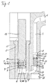
図3及び図4に関連してより一層明らかなように、内蔵閉止弁7を実現するために、鋳造プランジャー3は、鋳造シリンダー2の内壁10に対して密閉するように設置されていて、弁座11を含むプランジャースリーブ9と、弁本体13を含むプランジャーラム12と、を備える特定の構造を有している。明示した弁座11及び弁本体13は、この場合は任意であり、実際の閉止弁7を形成しており、かつ、この目的のために開放位置と閉鎖位置との間を相互に軸線方向に移動可能であるこれら2つの弁構成要素を区別できるように明示したにすぎない。好ましくは、通常は円状の線に沿った、閉鎖位置における線状接触状態が、対応する弁本体13の成形によって2つの弁構成要素11,13に提供される。或いは、閉鎖位置における2つの相互作用する弁構成要素11及び13の水平接触状態を実現するデザインを用いることができる。プランジャーラム12は、その軸線方向の端面において弁本体13を形成する第1のラム部12aと、たとえば、ねじ接続によって第1のラム部12aに固定される第2のラム部12bと、前記第2のラム部12b上に形成されるプランジャースリーブ移動制止部14と、を有している。第1のラム部12aは、関連するプランジャーロッド14と一体的に形成され得るか、又は図3及び図4に示すように、たとえば、ねじによって後者に固定され得る。プランジャースリーブ移動制止部14は、プランジャースリーブ9上に形成された対応する逆制止部15と相互作用するので、プランジャースリーブ9は、後退移動時に、第2のラム部12bと一緒に移動するようになっている。逆向きの前進移動において、プランジャースリーブ9は、弁座11及び弁本体13の弁閉鎖接触状態によって、第1のラム部12aと一緒に移動するようになっている。
As is more apparent in connection with FIGS. 3 and 4, in order to realize the built-in shut-off
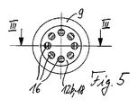
このように、上述した構造は、場合によっては、鋳造プランジャーを通る溶融材料の流れを可能にするとともに溶融材料の流れを遮断するために受動的に作動する逆止弁を実現する。この目的のために、第2のラム部12bは、複数の軸線方向における溶融材料の通路開口16を有しており、これら通路開口を介して、弁7が開放された状態の弁座11と弁本体13との間の弁ギャップを通過した溶融材料が、鋳造シリンダー2の鋳造室17として機能する先方の自由空間内に進入する。図5から理解できるように、図示する例では、8つの溶融材料の通路開口16が、第2のラム部12bの周方向において等間隔に分布するように設けられており、具体的には、第2のラム部12bによって形成されたディスク本体又はシリンダー本体18を貫くように設けられている。
Thus, the above-described structure in some cases provides a check valve that is actuated passively to allow molten material flow through the casting plunger and to block molten material flow. For this purpose, the second ram part 12b has a plurality of
図1〜図4に示すように、鋳造プランジャー閉止弁7の機能性は、2つの弁端部の位置から理解され得る。図1及び図3は、溶融吸引動作の間の弁7を示しており、溶融吸引動作において、鋳造プランジャー3は、従来の溶融ルツボ又は溶融槽(ここでは図示せず)から鋳造プランジャー3後方の鋳造シリンダー2内に溶融物を吸引するとともに鋳造プランジャー3を介して鋳造室17に溶融物を吸引するためにプランジャーロッド14によって引き戻される。閉止弁7が予め閉鎖されていた場合は、プランジャーロッド14の後退移動によって最初に閉止弁7が開放される。この際、プランジャーロッド14がプランジャーラム12及び弁本体13を引き戻すものの、プランジャースリーブ9は、鋳造シリンダー内壁10に対して圧迫作用と密閉作用を及ぼすような態様で存在することによって静止している。プランジャーラム12のプランジャースリーブ移動制止部14が、プランジャースリーブ9の対応する逆制止部15に対して隣接する場合に限り、プランジャースリーブ9に対する所定の弁ストロークHによるプランジャーラム12の相対移動によって、プランジャースリーブ9がプランジャーラム12の後退移動と一緒に移動するようになる。次いで、閉止弁7が開放位置にされることによって、溶融材料が鋳造プランジャー3を通って流れ得る。具体的に、溶融材料は、第1のラム部12aとプランジャースリーブ9との間の環状空間、弁座11と弁本体13との間の弁ギャップ、及び第2のラム部12bの通路開口16を通って流れ得る。
As shown in FIGS. 1-4, the functionality of the cast plunger shut-off
金型充填動作時の例にあるように、図2及び図4は、閉鎖位置における閉止弁7を示しており、プランジャーロッド14及び鋳造プランジャー3の前進移動によって、溶融材料は、鋳造室17からライザー管4を介して金型内に押し込まれる。プランジャーロッド14のこの前進移動の間に、第1のラム部12aの軸線方向の端面によって形成された弁本体13がプランジャースリーブ9上の弁座11まで前進移動する結果として、閉止弁7が鋳造プランジャー3を通る溶融材料の鋳造室17内への更なる流れを防止する閉鎖位置を達成するまでの間、最初は、鋳造シリンダー内壁10に対して緊密に支持されたプランジャースリーブ9が再び静止状態のまま維持される。プランジャースリーブ9の弁座11に対する第1のラム部12aの軸受接触状態によって、プランジャーラム12の前進移動においてプランジャーラム12がプランジャースリーブ9を一緒に運搬するようになる。
As shown in the example during the mold filling operation, FIGS. 2 and 4 show the closing
弁ストロークHは、第2のラム部12bがプランジャースリーブ移動制止部14によって第1のラム部12a又は弁本体13から可変的に設定可能な距離だけ離間して第1のラム部に固定され得るように、たとえば、第2のラム部12bが程度の差はあれ第1のラム部12aにねじ留めされるように、可変的に設定され得る。2つのラム部12a,12b間に挿入される対応するスペーサリング19の選択によって、第2のラム部12bが第1のラム部12aからどれくらい離れてねじ留めされるかを決定できる。さらに、スペーサリング19は、第1のラム部12a上に第2のラム部12bを確実に保持することに寄与する。弁ストロークHの寸法は、弁座11及び対応する弁本体13の設計及び寸法と同様に選択されることができ、これにより、通過する溶融材料の最適な流れ挙動、特に、乱流が可能な限り除かれた溶融流れが達成される。
The valve stroke H is fixed to the first ram portion by separating the second ram portion 12b from the
ライザー管閉止弁8は、軸線方向に移動できるようにライザー管4に組み込まれていてライザー管4の内壁21に対して支持されている弁本体20を含んでいる。弁本体20は、溶融材料を軸線方向に通過させるように軸線方向の両端部側面間に延在する管構造体を有しており、図1及び図2における軸線方向の下方の端部側面22は、切頭円錐形となるように形成されていてライザー管閉止弁8の弁座23と相互作用するようになっており、前記弁座23は、流れプロファイルを最適化する目的のために好ましくはアーチ状に構成された下方のライザー管部分24の開口によって形成されている。このアーチ状のライザー管部分24は、対応するアーチ状の孔を備える回転プラグ25によって示される実施例において実現されており、前記回転プラグ25が鋳造容器1の関連する受容孔26に差し込まれることによって、アーチ形のライザー管部分24が入口側において鋳造室出口開口5と整列されるようになる。弁座23から離れた軸線方向における他方の端部側面において、弁本体20は端部側面制止リング27で終端しており、端部側面制止リング27は、弁ストロークを制限するようにライザー管内壁21の対応する環状肩部28と相互作用する。すなわち、溶融圧力が下から機能する場合、環状肩部28を備えるライザー管4の制止リング27によって、弁本体20が当接するまで上向きに移動する。
The riser pipe shut-off
制止リング27は、弁本体20の管構造体の上方の出口側面部を形成する中央の軸線方向開口29を形成している。すなわち、制止リング27は、中央の軸線方向開口29を包囲している。さらに、図6〜図8の個別の例に関連して、より詳細に理解され得るように、この管構造体は、弁本体の外周の周辺に分布するように配列された複数の軸線方向の管スロット30を有しており、図示する例には4つのスロット30が存在しており、これらは弁本体20の弁座側の軸線方向における端部側面から端部側面制止リング27まで延在している。スロット30は、管構造体のそれぞれの半径方向の通路開口31を介して中央の軸線方向開口29に開口している。
The
開口29の径は、環状肩部28の上方に隣接するその一部分において、ライザー管4の径と同じか又はそれよりも大きい寸法になるように選択される。このことは、制止リング27が半径方向においてライザー管4内に突出しないという利点を有しており、それゆえに、ライザー管閉止弁が完全に開放されると(図2を参照)、ライザー管4内の溶融材料によって弁本体20を介して制止リング27に逆圧が作用することはない。むしろ、斯かる逆圧は、開口29の残存する接続部によって通路開口31及び軸線方向のスロット30を介して主に下向きに誘導されて弁座23によって吸収されるか、又は弁本体20に上向きに作用する弁の持ち上げ力に再び誘導される。逆圧として残存するのは、半径方向の通路開口31間の領域において弁本体の表面に下向きに作用する比較的小さな力だけである。換言すると、逆圧が開口29の縮小された断面のみに実質的に作用する一方で、制止リング27を含む弁本体20の有効断面の全体が上向きの圧力のために利用可能になる。従来のボール弁を使用する場合と比較して、弁挙動が大幅に改良され得る。
The diameter of the
そして、この目的のために、図1は、溶融吸引動作時のライザー管閉止弁8の位置を示している。鋳造室17の負圧形成によって、ライザー管閉止弁8は図示する閉鎖位置に留まる。閉鎖位置では、金型充填動作の終了後に鋳造室17及びライザー管4内の溶融材料から圧力が除去されると、ライザー管閉止弁8が直ちに重力によって落下する。
For this purpose, FIG. 1 shows the position of the riser
金型充填動作の間に、鋳造室17及び先方のライザー管部分24の溶融圧力によって、ライザー管閉止弁8の弁本体20が図2による開放位置に持ち上げられる。開放位置において、弁本体20は、その上部制止リング27によってライザー管の環状肩部28に対して静止する。この位置において、溶融材料は、上述した管構造体(すなわち、軸線方向のスロット30、半径方向の通路開口31、及び中央の軸線方向開口29)を介して弁本体20を通ってライザー管4に上向きに流入し得るとともに、従来の方式によって金型に圧入され得る。制止リング27が、ライザー管の環状肩部28に対して完全に静止するので、上述したように、底部から頂部よりも頂部から底部の方が小さい有効断面にわたって溶融圧力が弁本体20に作用することになり、それにより、流動する溶融物が存在しないか又はその体積が微小である場合であっても、依然として、溶融圧力が弁を開放するように作用する。その結果、このライザー管閉止弁8は、たとえば、金型内の金属溶融材料を圧縮するための金属ダイカストにおいて所望されるような、金型充填動作の終盤の凝固段階の間における少量の溶融流れをも可能にする。金型充填動作のこの期間には、非常に少ない溶融量しか送達されず、如何なる顕著な流れ力も発生しない。従来のボール弁であればこの時点で閉鎖し得るものの、これは本発明のライザー管閉止弁によって回避される。金型充填動作の終了後に、圧力が除去される場合に限り、弁本体20が重力によって弁座23上に落下し、その結果、ライザー管閉止弁8が閉鎖して、ライザー管4内の溶融物が鋳造室17まで下向きに逆流することを防止する。
During the mold filling operation, the
図示する例において、弁本体20は円筒状である。その結果、弁本体が比較的長い軸線の長さにわたってライザー管内壁21に対して支持され得るので、所望しない移動若しくは動作を妨げる揺動、又は弁本体20の傾きを確実に回避できる。管構造体29,30,31は、弁本体20の確定した貫通流を提供し、その結果、ライザー管4内の溶融材料の流れ挙動を最適化できるか、又は流れ挙動を閉止弁の配置によって概ねスムーズに維持できる。当然、弁本体が本発明によって説明された機能性を実行する限り、ライザー管閉止弁のための弁本体の他の代替的な形態を使用してもよい。このことは、送達される溶融材料を備える弁本体の貫通流のための管構造の代替的な形態にも適用される。
In the illustrated example, the
さらに、上述の説明からも明らかなように、図1、図2、及び図6〜図8に示すライザー管閉止弁は、受動的に作動する逆止弁として実現される。能動的に作動可能な弁としての本発明の具体例は、この弁8及び鋳造プランジャーに内蔵された閉止弁7の双方についても実現可能である。この目的のために、図9及び図10は、双方の弁が能動的に制御可能な弁として実現される例示的な実施形態を示しており、ここでは、双方の弁が、たとえば、空気圧若しくは水圧、又は電動によって作動可能な弁として実現されている。或いは、本発明は、2つの弁のうちのいずれか一方が、受動的に作動する逆止弁として設計され、他方が能動的に作動可能な弁として設計される実施形態も当然含んでいる。理解をより容易にするために、弁の位置に関して図1及び図2にそれぞれ対応する図9及び図10の例示的な実施形態における同一又は機能的に同等の構成要素には同一の符号が使用されており、上記の構成要素に関する上述した説明が、この点において参照され得る。
Further, as is apparent from the above description, the riser pipe closing valve shown in FIGS. 1, 2, and 6 to 8 is realized as a passively operated check valve. The embodiment of the invention as an actively actuable valve can be realized both for this
図9及び図10から理解され得るように、図示される鋳造装置は、鋳造プランジャー閉止弁7のための水圧アクチュエーター又は空気圧アクチュエーターと、ライザー管閉止弁8のための電動アクチュエーターと、を有している。この目的のために、ライザー管閉止弁8では、弁本体20が上部制止リング27(この目的のために拡張されている)において線状サーボモーター41に制御ロッド40を介して連結されている。制御ロッド40は、ライザー管孔4に隣接する鋳造容器1において、対応する通路孔を通って案内されていて、サーボモーター41によって軸線方向の前後に移動可能である。その結果、ライザー管4における弁本体20の位置を、受動的な弁デザインの例について上述した重力の効果及び溶融圧力とは無関係に、能動的に設定できるようになる。受動的な弁デザインについて上述した内容は、それぞれの所望の弁位置に類似して適用される。
As can be seen from FIGS. 9 and 10, the illustrated casting apparatus has a hydraulic or pneumatic actuator for the casting
たとえば、先方の口金における維持又は交換作業のために、ライザー管閉止弁8の能動的な作動性を利用して、特に、弁8が開放されているときに必要に応じてライザー管4から鋳造室17に溶融材料を逆流させること、及び少なくとも部分的にライザー管4を空にすることが可能である。受動的なデザインのライザー管閉止弁8の場合、たとえば、閉鎖位置における密閉作用に関する弁8の対応する形態によって、溶融材料が閉鎖位置の弁8を通ってライザー管4から所定の逆流経路を経由して鋳造室17に所定の低い逆流速度で逆流し得ることを保証できる点で、この必要に応じた機能性を実現できる。
For example, the active operability of the riser pipe shut-off
鋳造プランジャー閉止弁7のために図示するのは、プランジャーロッド14及び鋳造プランジャー3に内蔵された水圧アクチュエーター又は空気圧アクチュエーターである。圧力空間42は、特に、この目的のために、プランジャーロッド14に組み込まれており、前記圧力空間42は、圧力プランジャー43によって分割されており、圧力空間の各半分のための関連する圧力媒体管44,45は、プランジャーロッド14を横断している。圧力プランジャー43は、プランジャーロッド14及びプランジャーラム12の中心を通って鋳造プランジャー底部46まで軸線方向に延在する制御ロッド46に連結されており、この例示的な実施形態では、この程度まで改良されたプランジャースリーブ9が鋳造プランジャー底部46によって終端されている。制御ロッド46は、たとえば、ねじ接続によってプランジャースリーブ底面47に固定されており、その結果、プランジャースリーブ9は、プランジャーラム12に対する制御ロッド46の対応する軸線方向の前後移動によって能動的に移動可能である。この目的のために、圧力室42の2つの部分には、関連する圧力媒体、例えば、空気、その他の気体、又は流体の正圧又は負圧が従来の方式で適切に加えられる。このようにして、鋳造プランジャー閉止弁7は、上述した受動的な弁デザインの場合に生じる弁作動力に加えて、又はその代わりに、能動的に開放位置と閉鎖位置の間を移動可能である。
Illustrated for the cast
上に示され説明された例示的な実施形態の代わりに、本発明は、本発明による鋳造プランジャー閉止弁、及び本発明によるライザー管閉止弁の双方を備えていないものの、本発明による1つの鋳造プランジャー閉止弁、又は本発明による1つのライザー管閉止弁のみを備えている実施形態をも含むことは言うまでもない。いずれの場合にも、他の弁は完全に欠落しているか、又はこの用途のために公知である従来の弁によって置換されている。したがって、たとえば、ライザーラインにおいて従来の閉止弁を一切有していないか又は従来の閉止弁を1つだけ有しており、かつ、構造が異なるため斯かる閉止弁を必要としない鋳造装置における従来の鋳造プランジャーの代わりに、内蔵閉止弁を有する本発明による鋳造プランジャーを使用してもよい。同様に、本発明の対応する実施形態では、従来の鋳造プランジャーの同時使用、たとえば、鋳造室への溶融流れが鋳造プランジャーを通ってではなく別の方法で発生するような用途のために、本発明によるライザー管閉止弁のみが設けられていてもよい。 Instead of the exemplary embodiment shown and described above, the present invention does not comprise both a cast plunger shut-off valve according to the invention and a riser pipe shut-off valve according to the invention. Needless to say, embodiments include only a cast plunger stop valve or only one riser tube stop valve according to the present invention. In either case, the other valve is either completely missing or replaced by a conventional valve known for this application. Thus, for example, a conventional casting apparatus that does not have any conventional closing valve in the riser line or has only one conventional closing valve and does not require such a closing valve due to the different structure. Instead of the cast plunger, a cast plunger according to the invention having a built-in shut-off valve may be used. Similarly, in a corresponding embodiment of the present invention, for simultaneous use of conventional casting plungers, for example applications where the melt flow to the casting chamber occurs in a different manner than through the casting plunger. Only the riser pipe closing valve according to the present invention may be provided.
本発明による鋳造プランジャー、及び本発明による鋳造装置は、熱加圧室式ダイカスト機だけでなく、斯かる機能性を有する鋳造プランジャー又は鋳造装置を備えるように意図された他の種類の鋳造機にも使用できることも言うまでもない。 The casting plunger according to the invention and the casting apparatus according to the invention are not only hot-pressurized chamber die casting machines, but also other types of castings intended to comprise a casting plunger or casting device having such functionality. Needless to say, it can also be used for machines.
Claims (10)
弁座(11)及び前記弁座(11)と相互作用する弁本体(13)を有していて前記鋳造プランジャーに内蔵されている鋳造プランジャー閉止弁(7)を備えており、
前記鋳造プランジャー閉止弁(7)は、開放位置において、溶融物吸引動作の間に前記鋳造プランジャーを通る溶融材料の流れを可能にするとともに、閉鎖位置において、金型充填動作の間に前記流れを遮断するようになっており、
前記鋳造プランジャーは、前記鋳造装置の鋳造シリンダー(2)の内壁(10)に対して配置可能であって弁座(11)を含んでいるプランジャースリーブ(9)と、前記弁本体(13)を含むプランジャーラム(12)と、を備えており、
前記プランジャースリーブ(9)及び前記プランジャーラム(12)が軸線方向において所定の弁ストロークで相互に移動可能であり、
前記プランジャーラム(12)が、前記弁本体を有する第1のラム部(12a)と、プランジャースリーブ移動制止部(14)を有していて前記第1のラム部(12a)に配置される第2のラム部(12b)と、を備えており、
前記第2のラム部(12b)が、ディスク本体又はシリンダー本体と、前記ディスク本体又はシリンダー本体を貫く、複数の軸線方向における溶融材料の通路開口(16)と、を備えていることを特徴とする、鋳造プランジャー。 A casting plunger for a casting machine of a casting machine,
A cast plunger closing valve (7) having a valve seat (11) and a valve main body (13) interacting with the valve seat (11) and built in the cast plunger;
The casting plunger shut-off valve (7) allows the flow of molten material through the casting plunger during the melt suction operation in the open position and the mold plunger during the mold filling operation in the closed position. To block the flow,
The casting plunger can be arranged with respect to the inner wall (10) of the casting cylinder (2) of the casting apparatus and includes a plunger sleeve (9) including a valve seat (11), and the valve body (13). A plunger ram (12) including
Said plunger sleeve (9) and Ri movable der to each other at a predetermined valve stroke in the plunger ram (12) is axially,
The plunger ram (12) has a first ram portion (12a) having the valve body and a plunger sleeve movement restraining portion (14), and is arranged on the first ram portion (12a). A second ram part (12b),
The second ram portion (12b) includes a disk body or cylinder body, and a plurality of axial passages (16) of molten material that penetrate the disk body or cylinder body. A casting plunger.
前記鋳造プランジャーが請求項1〜4のいずれか1つに記載の鋳造プランジャーであることを特徴とする、鋳造装置。 A casting apparatus for a casting machine, comprising: a casting container having a casting cylinder; and a casting plunger arranged to be movable in an axial direction in the casting cylinder,
Characterized in that the casting plunger is cast plunger according to any one of claims 1-4, casting apparatus.
前記ライザー管閉止弁(8)は、閉鎖位置において、溶融物吸引動作の間に、前記ライザー管を通る溶融材料の流れを遮断するとともに、開放位置において、金型充填動作時に前記流れを可能にするようになっており、
前記ライザー管閉止弁(8)は、軸線方向に移動可能に前記ライザー管に組み込まれていてライザー管内壁(21)に対して支持されている円筒状の弁本体(20)を有するとともに、溶融材料を軸線方向に通過させるように軸線方向に延在する管構造体を含んでおり、
前記管構造体が、前記管構造体の出口側面部を形成する軸線方向開口(29)を含み、
前記弁本体の2つの軸線方向の端部側面のうちのいずれか一方の端部側面(22)は、前記閉止弁の弁座(23)と相互作用し、
前記弁座(23)から離れた前記弁本体の軸線方向の端部側面は、前記軸線方向開口(29)を形成する端部側面制止リング(27)で終端し、弁ストロークを制限するように前記ライザー管内壁の対応する環状肩部(28)と相互作用することを特徴とする鋳造装置。 A casting apparatus for a casting machine, comprising: a casting container (1) provided with a riser pipe (4); and a riser pipe closing valve (8) in the riser pipe,
The riser pipe closure valve (8) is in the closed position, between the melt suction operation, while blocking the flow of molten material through the riser pipe, in the open position, the flow can at the time of mold filling operation Is supposed to
The riser pipe closing valve (8) has a cylindrical valve body (20) which is incorporated in the riser pipe so as to be movable in the axial direction and is supported with respect to the riser pipe inner wall (21), and is melted. includes a tube structure which extends in the axial direction so as to pass the material in the axial direction,
The tube structure includes an axial opening (29) forming an outlet side of the tube structure;
Either one of the two axial end sides of the valve body side surface (22) interacts with the valve seat (23) of the stop valve ;
The axial side surface of the valve body remote from the valve seat (23) terminates with an end side stop ring (27) forming the axial opening (29) to limit the valve stroke. Casting device characterized in that it interacts with a corresponding annular shoulder (28) of the inner wall of the riser tube .
前記鋳造プランジャーが請求項1〜4のいずれか1つに記載の鋳造プランジャーであることを特徴とする、請求項6に記載の鋳造装置。 A casting plunger arranged to be axially movable in the casting cylinder of the casting vessel;
The casting apparatus according to claim 6 , wherein the casting plunger is the casting plunger according to any one of claims 1 to 4 .
Applications Claiming Priority (3)
| Application Number | Priority Date | Filing Date | Title |
|---|---|---|---|
| DE102011017610A DE102011017610B3 (en) | 2011-04-27 | 2011-04-27 | Casting piston and casting unit with shut-off valve |
| DE102011017610.1 | 2011-04-27 | ||
| PCT/EP2012/053288 WO2012146408A1 (en) | 2011-04-27 | 2012-02-27 | Casting plunger and casting unit with shut-off valve |
Publications (3)
| Publication Number | Publication Date |
|---|---|
| JP2014512274A JP2014512274A (en) | 2014-05-22 |
| JP2014512274A5 JP2014512274A5 (en) | 2015-01-08 |
| JP5878624B2 true JP5878624B2 (en) | 2016-03-08 |
Family
ID=45774204
Family Applications (1)
| Application Number | Title | Priority Date | Filing Date |
|---|---|---|---|
| JP2014506797A Active JP5878624B2 (en) | 2011-04-27 | 2012-02-27 | Casting plunger having a shut-off valve and casting apparatus |
Country Status (17)
| Country | Link |
|---|---|
| US (1) | US9505053B2 (en) |
| EP (1) | EP2701866B1 (en) |
| JP (1) | JP5878624B2 (en) |
| KR (1) | KR101962342B1 (en) |
| CN (1) | CN103596714B (en) |
| BR (1) | BR112013027599B1 (en) |
| DE (1) | DE102011017610B3 (en) |
| DK (1) | DK2701866T3 (en) |
| ES (1) | ES2708377T3 (en) |
| HU (1) | HUE042185T2 (en) |
| MX (1) | MX362093B (en) |
| PL (1) | PL2701866T3 (en) |
| PT (1) | PT2701866T (en) |
| RU (1) | RU2598069C2 (en) |
| SI (1) | SI2701866T1 (en) |
| TR (1) | TR201820511T4 (en) |
| WO (1) | WO2012146408A1 (en) |
Families Citing this family (6)
| Publication number | Priority date | Publication date | Assignee | Title |
|---|---|---|---|---|
| DE102012010923A1 (en) * | 2012-06-04 | 2013-12-05 | Gebr. Krallmann Gmbh | Delivery device for a molten metal in an injection pressure unit |
| DE102014018796A1 (en) * | 2014-12-19 | 2016-06-23 | Gebr. Krallmann Gmbh | Delivery device for a molten metal in an injection molding unit |
| DE102015224414A1 (en) * | 2015-12-07 | 2017-06-08 | Volkswagen Aktiengesellschaft | cast device |
| AU2021200246A1 (en) * | 2020-01-31 | 2021-08-19 | Howmedica Osteonics Corp. | Injection molding feedstock delivery system |
| DE102020207016A1 (en) | 2020-06-04 | 2021-12-09 | Oskar Frech Gmbh + Co. Kg | Casting unit for a die casting machine |
| DE102020207704A1 (en) | 2020-06-22 | 2021-12-23 | Oskar Frech Gmbh + Co. Kg | Die casting machine and operating method |
Family Cites Families (18)
| Publication number | Priority date | Publication date | Assignee | Title |
|---|---|---|---|---|
| BE351505A (en) * | ||||
| US5040589A (en) * | 1989-02-10 | 1991-08-20 | The Dow Chemical Company | Method and apparatus for the injection molding of metal alloys |
| CA2008990A1 (en) * | 1990-01-31 | 1991-07-31 | George Sodderland | Delivery means for conveying a fixed charge of molten metal to a mold cavity of a die-casting machine |
| US5401161A (en) * | 1991-06-14 | 1995-03-28 | Long; Michael C. | Injection molding valve |
| JP2517509B2 (en) * | 1992-01-30 | 1996-07-24 | 日本軽金属株式会社 | Hot chamber-plunger for die casting machine injection |
| DE4419848C1 (en) * | 1994-06-07 | 1995-12-21 | Frech Oskar Gmbh & Co | Hot chamber die casting machine |
| JP3179289B2 (en) * | 1994-07-22 | 2001-06-25 | 宇部興産株式会社 | Magnesium water heater |
| JP2000117417A (en) * | 1998-10-20 | 2000-04-25 | Toshiba Mach Co Ltd | Molten metal supplying pump device |
| JP3409154B2 (en) * | 1998-12-28 | 2003-05-26 | 株式会社日本製鋼所 | Backflow prevention device of metal injection molding machine |
| DE19928770B8 (en) * | 1999-02-19 | 2006-08-03 | Krauss-Maffei Kunststofftechnik Gmbh | injection molding machine |
| JP2001293553A (en) * | 2000-04-13 | 2001-10-23 | Kubota Corp | Device for pouring molten metal |
| ES2262479T3 (en) * | 2000-10-31 | 2006-12-01 | Oskar Frech Gmbh + Co. Kg | DEVICE FOR THE MANUFACTURE OF PRESSED MOLDED METAL PARTS, IN PARTICULAR NON-FERREAL METALS. |
| JP2002336947A (en) | 2001-05-14 | 2002-11-26 | Minoru Kai | Apparatus for automatically supplying molten light metal |
| CA2463281C (en) | 2004-04-05 | 2007-11-13 | Husky Injection Molding Systems Ltd. | Non-return valve for use in a molding system |
| US7291006B2 (en) * | 2004-06-24 | 2007-11-06 | Husky Injection Molding Systems Ltd. | Check valve lip seal for an injection molding machine |
| DE102004051105A1 (en) * | 2004-10-19 | 2006-04-27 | Billion S.A. | Plasticizing and injection device |
| US7425126B2 (en) * | 2006-05-17 | 2008-09-16 | Husky Injection Molding Systems Ltd. | Molding-system valve having knockdown retainer |
| DE202009004299U1 (en) * | 2009-03-06 | 2009-06-25 | Schoch, Gerhard | Casting container for a hot chamber die casting machine |
-
2011
- 2011-04-27 DE DE102011017610A patent/DE102011017610B3/en active Active
-
2012
- 2012-02-27 MX MX2013012517A patent/MX362093B/en active IP Right Grant
- 2012-02-27 RU RU2013151382/02A patent/RU2598069C2/en active
- 2012-02-27 PL PL12706559T patent/PL2701866T3/en unknown
- 2012-02-27 TR TR2018/20511T patent/TR201820511T4/en unknown
- 2012-02-27 EP EP12706559.7A patent/EP2701866B1/en active Active
- 2012-02-27 SI SI201231529T patent/SI2701866T1/en unknown
- 2012-02-27 PT PT12706559T patent/PT2701866T/en unknown
- 2012-02-27 HU HUE12706559A patent/HUE042185T2/en unknown
- 2012-02-27 ES ES12706559T patent/ES2708377T3/en active Active
- 2012-02-27 US US14/113,979 patent/US9505053B2/en active Active
- 2012-02-27 BR BR112013027599A patent/BR112013027599B1/en active IP Right Grant
- 2012-02-27 DK DK12706559.7T patent/DK2701866T3/en active
- 2012-02-27 CN CN201280020890.1A patent/CN103596714B/en active Active
- 2012-02-27 KR KR1020137029641A patent/KR101962342B1/en active IP Right Grant
- 2012-02-27 WO PCT/EP2012/053288 patent/WO2012146408A1/en active Application Filing
- 2012-02-27 JP JP2014506797A patent/JP5878624B2/en active Active
Also Published As
| Publication number | Publication date |
|---|---|
| PL2701866T3 (en) | 2019-06-28 |
| TR201820511T4 (en) | 2019-01-21 |
| RU2598069C2 (en) | 2016-09-20 |
| BR112013027599A2 (en) | 2017-02-14 |
| US9505053B2 (en) | 2016-11-29 |
| BR112013027599B1 (en) | 2020-01-28 |
| EP2701866B1 (en) | 2018-11-14 |
| EP2701866A1 (en) | 2014-03-05 |
| DK2701866T3 (en) | 2019-03-04 |
| CN103596714B (en) | 2016-09-21 |
| MX2013012517A (en) | 2014-02-03 |
| KR20140021660A (en) | 2014-02-20 |
| CN103596714A (en) | 2014-02-19 |
| ES2708377T3 (en) | 2019-04-09 |
| HUE042185T2 (en) | 2019-06-28 |
| KR101962342B1 (en) | 2019-05-27 |
| PT2701866T (en) | 2019-02-21 |
| DE102011017610B3 (en) | 2012-06-21 |
| MX362093B (en) | 2019-01-07 |
| US20140042193A1 (en) | 2014-02-13 |
| WO2012146408A1 (en) | 2012-11-01 |
| RU2013151382A (en) | 2015-06-10 |
| SI2701866T1 (en) | 2019-03-29 |
| JP2014512274A (en) | 2014-05-22 |
Similar Documents
| Publication | Publication Date | Title |
|---|---|---|
| JP5878624B2 (en) | Casting plunger having a shut-off valve and casting apparatus | |
| CN107000047B (en) | Die pump | |
| JP6763040B2 (en) | Die casting machine with injection assembly with shutoff valve | |
| JP2003515510A (en) | Filling spout whose flow rate can be adjusted by one actuator | |
| EA025480B1 (en) | Delivery device for a molten metal in an injection press | |
| CN107614235B (en) | It is used in the wax injector and injection nozzle of lost-wax casting | |
| US3651825A (en) | Stopper plug valve for hot metal ladles | |
| JP2014512274A5 (en) | ||
| JP6992085B2 (en) | Non-iron alloy hot chamber die casting equipment | |
| JP2020508245A (en) | Hot runner device with overload protection device | |
| JP2021186882A (en) | Casting unit for die casting machine | |
| JP2016087686A (en) | Exhaustion valve assembly in die-casting mold | |
| US6105658A (en) | Process and device for filling a casting tool with a metal melt | |
| JP5556108B2 (en) | Semi-molten metal casting method and semi-molten metal casting apparatus | |
| KR20180118742A (en) | Die casting nozzle system | |
| JP5801754B2 (en) | Melting apparatus and injection molding apparatus | |
| JP2020500720A (en) | Injection assembly for pressurized die casting system | |
| JP5471476B2 (en) | Closure device and closure method | |
| RU2495310C1 (en) | Control valve | |
| CN110177635A (en) | The die-casting system of amorphous alloy | |
| JP2018538145A (en) | Strand / pipe extrusion press or metal strand extrusion press | |
| US9931693B2 (en) | Filtering check valve for metal casting | |
| CN214031657U (en) | Gas injection mechanism in isobaric filling valve | |
| CN112357863A (en) | Gas injection mechanism in isobaric filling valve | |
| JP5324940B2 (en) | Injection device and injection method |
Legal Events
| Date | Code | Title | Description |
|---|---|---|---|
| A521 | Request for written amendment filed |
Free format text: JAPANESE INTERMEDIATE CODE: A523 Effective date: 20141112 |
|
| A621 | Written request for application examination |
Free format text: JAPANESE INTERMEDIATE CODE: A621 Effective date: 20141112 |
|
| A977 | Report on retrieval |
Free format text: JAPANESE INTERMEDIATE CODE: A971007 Effective date: 20150610 |
|
| A131 | Notification of reasons for refusal |
Free format text: JAPANESE INTERMEDIATE CODE: A131 Effective date: 20150630 |
|
| A601 | Written request for extension of time |
Free format text: JAPANESE INTERMEDIATE CODE: A601 Effective date: 20150929 |
|
| A521 | Request for written amendment filed |
Free format text: JAPANESE INTERMEDIATE CODE: A523 Effective date: 20151119 |
|
| TRDD | Decision of grant or rejection written | ||
| A01 | Written decision to grant a patent or to grant a registration (utility model) |
Free format text: JAPANESE INTERMEDIATE CODE: A01 Effective date: 20160105 |
|
| A61 | First payment of annual fees (during grant procedure) |
Free format text: JAPANESE INTERMEDIATE CODE: A61 Effective date: 20160128 |
|
| R150 | Certificate of patent or registration of utility model |
Ref document number: 5878624 Country of ref document: JP Free format text: JAPANESE INTERMEDIATE CODE: R150 |
|
| R250 | Receipt of annual fees |
Free format text: JAPANESE INTERMEDIATE CODE: R250 |
|
| R250 | Receipt of annual fees |
Free format text: JAPANESE INTERMEDIATE CODE: R250 |
|
| R250 | Receipt of annual fees |
Free format text: JAPANESE INTERMEDIATE CODE: R250 |
|
| R250 | Receipt of annual fees |
Free format text: JAPANESE INTERMEDIATE CODE: R250 |
|
| R250 | Receipt of annual fees |
Free format text: JAPANESE INTERMEDIATE CODE: R250 |
|
| R250 | Receipt of annual fees |
Free format text: JAPANESE INTERMEDIATE CODE: R250 |