JP5877205B2 - Intra-annular mounting frame for aortic valve repair - Google Patents
Intra-annular mounting frame for aortic valve repair Download PDFInfo
- Publication number
- JP5877205B2 JP5877205B2 JP2013531901A JP2013531901A JP5877205B2 JP 5877205 B2 JP5877205 B2 JP 5877205B2 JP 2013531901 A JP2013531901 A JP 2013531901A JP 2013531901 A JP2013531901 A JP 2013531901A JP 5877205 B2 JP5877205 B2 JP 5877205B2
- Authority
- JP
- Japan
- Prior art keywords
- mounting frame
- intra
- annular mounting
- millimeters
- annulus
- Prior art date
- Legal status (The legal status is an assumption and is not a legal conclusion. Google has not performed a legal analysis and makes no representation as to the accuracy of the status listed.)
- Active
Links
Images


Classifications
-
- A—HUMAN NECESSITIES
- A61—MEDICAL OR VETERINARY SCIENCE; HYGIENE
- A61F—FILTERS IMPLANTABLE INTO BLOOD VESSELS; PROSTHESES; DEVICES PROVIDING PATENCY TO, OR PREVENTING COLLAPSING OF, TUBULAR STRUCTURES OF THE BODY, e.g. STENTS; ORTHOPAEDIC, NURSING OR CONTRACEPTIVE DEVICES; FOMENTATION; TREATMENT OR PROTECTION OF EYES OR EARS; BANDAGES, DRESSINGS OR ABSORBENT PADS; FIRST-AID KITS
- A61F2/00—Filters implantable into blood vessels; Prostheses, i.e. artificial substitutes or replacements for parts of the body; Appliances for connecting them with the body; Devices providing patency to, or preventing collapsing of, tubular structures of the body, e.g. stents
- A61F2/02—Prostheses implantable into the body
- A61F2/24—Heart valves ; Vascular valves, e.g. venous valves; Heart implants, e.g. passive devices for improving the function of the native valve or the heart muscle; Transmyocardial revascularisation [TMR] devices; Valves implantable in the body
- A61F2/2412—Heart valves ; Vascular valves, e.g. venous valves; Heart implants, e.g. passive devices for improving the function of the native valve or the heart muscle; Transmyocardial revascularisation [TMR] devices; Valves implantable in the body with soft flexible valve members, e.g. tissue valves shaped like natural valves
- A61F2/2418—Scaffolds therefor, e.g. support stents
-
- A—HUMAN NECESSITIES
- A61—MEDICAL OR VETERINARY SCIENCE; HYGIENE
- A61F—FILTERS IMPLANTABLE INTO BLOOD VESSELS; PROSTHESES; DEVICES PROVIDING PATENCY TO, OR PREVENTING COLLAPSING OF, TUBULAR STRUCTURES OF THE BODY, e.g. STENTS; ORTHOPAEDIC, NURSING OR CONTRACEPTIVE DEVICES; FOMENTATION; TREATMENT OR PROTECTION OF EYES OR EARS; BANDAGES, DRESSINGS OR ABSORBENT PADS; FIRST-AID KITS
- A61F2/00—Filters implantable into blood vessels; Prostheses, i.e. artificial substitutes or replacements for parts of the body; Appliances for connecting them with the body; Devices providing patency to, or preventing collapsing of, tubular structures of the body, e.g. stents
- A61F2/02—Prostheses implantable into the body
- A61F2/24—Heart valves ; Vascular valves, e.g. venous valves; Heart implants, e.g. passive devices for improving the function of the native valve or the heart muscle; Transmyocardial revascularisation [TMR] devices; Valves implantable in the body
- A61F2/2442—Annuloplasty rings or inserts for correcting the valve shape; Implants for improving the function of a native heart valve
- A61F2/2445—Annuloplasty rings in direct contact with the valve annulus
-
- A—HUMAN NECESSITIES
- A61—MEDICAL OR VETERINARY SCIENCE; HYGIENE
- A61F—FILTERS IMPLANTABLE INTO BLOOD VESSELS; PROSTHESES; DEVICES PROVIDING PATENCY TO, OR PREVENTING COLLAPSING OF, TUBULAR STRUCTURES OF THE BODY, e.g. STENTS; ORTHOPAEDIC, NURSING OR CONTRACEPTIVE DEVICES; FOMENTATION; TREATMENT OR PROTECTION OF EYES OR EARS; BANDAGES, DRESSINGS OR ABSORBENT PADS; FIRST-AID KITS
- A61F2230/00—Geometry of prostheses classified in groups A61F2/00 - A61F2/26 or A61F2/82 or A61F9/00 or A61F11/00 or subgroups thereof
- A61F2230/0063—Three-dimensional shapes
- A61F2230/0073—Quadric-shaped
- A61F2230/0076—Quadric-shaped ellipsoidal or ovoid
Description
関連出願の相互参照
本願は、2010年9月30日に出願した米国特許仮出願第61/388573号の利益を主張し、その内容全体を参照によって本書に援用する。
This application claims the benefit of US Provisional Application No. 61 / 388,573 filed Sep. 30, 2010, the entire contents of which are hereby incorporated by reference.
1.発明の分野
本開示は、大動脈弁の修復を含む用途に有用な楕円形の装着フレームに関する。特に、本開示は、大動脈弁輪中に直接挿置されるように設計された楕円形の弁輪内装着フレームに関する。また、本開示は、楕円形の弁輪内装着フレームの挿置および移植のための方法、並びに上行大動脈DACRON(登録商標)グラフトおよび心膜単一または複数尖補綴のような相補的装置も含む。
1. The present disclosure relates to an elliptical mounting frame useful for applications involving aortic valve repair. In particular, the present disclosure relates to an elliptical intra-annular mounting frame designed to be inserted directly into an aortic annulus. The present disclosure also includes a method for insertion and implantation of an oval intra-annular mounting frame, and complementary devices such as the ascending aorta DACRON® graft and pericardial single or multiple apex prostheses. .
2.関連技術の記述
哺乳類の心臓は本質的に、化学機械的エネルギ変換器として機能するポンプである。代謝基質および酸素の化学エネルギは血圧の機械エネルギに変換され、心収縮中に心筋サルコメアによって流動する。該ポンプは、収縮期と呼ばれる収縮/駆出期および拡張期と呼ばれる弛緩/充満期を1〜2Hzの周波数で周期的に繰り返す。
2. 2. Description of Related Art The mammalian heart is essentially a pump that functions as a chemical mechanical energy converter. Metabolite and oxygen chemical energy is converted to mechanical energy for blood pressure and is flowed by myocardial sarcomere during systole. The pump periodically repeats a systole / ejection phase called systole and a relaxation / full phase called diastole at a frequency of 1-2 Hz.
ヒトの心臓は心臓血管系、すなわち肺循環および体循環から成る2つの並列循環を有する系の中心である。肺循環は大静脈から血液を右心房および右心室内に受け入れ、次いで心拍出量を肺動脈内および肺全体に送り出す。体循環は肺静脈から血液を受け入れ、左心房および左心室を介して心拍出量を大動脈、全身動脈、毛細血管、および静脈に送り出し、最終的に血液を大静脈に戻す。上方のチャンバすなわち左心房とポンプチャンバすなわち左心室との間に、僧帽弁が位置する。左心房は、心周期全体を通して肺静脈を介して肺から血液を受け入れるキャパシタ機能を果たす。左心室は拡張期に僧帽弁が開いたときに左心房から血液を受け入れることによって充満し、次いで収縮期に僧帽弁は閉じて、左心室から上行大動脈への血液の前方拍出を可能にする。左心室と大動脈との間には大動脈弁が位置し、正常な状態で、収縮期に心室から大動脈へのスムーズな血流を可能にするように働く。拡張期には、大動脈弁が閉じて左心室への逆流を防止する。 The human heart is the heart of the cardiovascular system, a system with two parallel circulations consisting of pulmonary circulation and systemic circulation. Pulmonary circulation accepts blood from the vena cava into the right atrium and right ventricle, and then pumps cardiac output into the pulmonary artery and throughout the lung. Systemic circulation receives blood from the pulmonary veins, pumps cardiac output through the left atrium and left ventricle to the aorta, systemic arteries, capillaries, and veins, and finally returns the blood to the vena cava. A mitral valve is located between the upper chamber or left atrium and the pump chamber or left ventricle. The left atrium serves as a capacitor that receives blood from the lungs through the pulmonary veins throughout the cardiac cycle. The left ventricle fills by accepting blood from the left atrium when the mitral valve opens during diastole, then closes during the systole to allow blood to pump forward from the left ventricle into the ascending aorta To. An aortic valve is located between the left ventricle and the aorta and works in a normal state to allow smooth blood flow from the ventricle to the aorta during systole. During diastole, the aortic valve closes to prevent backflow into the left ventricle.
患者の自己弁の外科的再建は、僧帽弁疾患の標準になりつつある。僧帽弁逸脱、純粋弁輪拡張、虚血性僧帽弁逆流、または僧帽弁心内膜炎のいずれを考慮するかに関わらず、修復術は今や常法であり、成功率が高く、関連する遅発性不全率も低い。リウマチ性僧帽弁疾患の場合でさえ、多くの外科医が積極的修復のプログラムに乗り出し、弁輪形成術にグルタルアルデヒド固定自己心膜による後尖増強技術、狭窄僧帽弁下装置の切除と人工GORE−TEX(登録商標)腱索の挿置、弁葉脱灰等を追加している。現在の目標は、僧帽弁疾患の100%に近い修復率を達成し、かつ人工弁置換術を著しく減少させることである。この状況における置換術に対する修復術の利点は充分に立証されている。(他の因子に対し正規化した)手術死亡率は低く、洞律動に抗凝血は不要であり、弁関連合併症は人工弁の場合より少なく、患者自身の組織が変質しないので耐久性は優れており、存在する異物が少ないので遅発性心内膜炎は低減される。したがって、僧帽弁疾患に対するこれらの概念は、心臓外科の分野で急速に標準治療になりつつある。 Surgical reconstruction of the patient's self-valve is becoming the standard for mitral valve disease. Regardless of whether mitral valve prolapse, pure annulus dilatation, ischemic mitral regurgitation, or mitral endocarditis is considered, repair is now a routine procedure with a high success rate and relevance The rate of late onset failure is also low. Even in the case of rheumatic mitral valve disease, many surgeons have embarked on an active repair program, annuloplasty with glutaraldehyde-fixed autopericardial posterior leaflet augmentation, stenotic mitral valve resection and artificial prosthesis Insertion of GORE-TEX (registered trademark) chords, leaflet decalcification, and the like are added. The current goal is to achieve a repair rate close to 100% of mitral valve disease and significantly reduce prosthetic valve replacement. The benefits of repair versus replacement in this situation are well documented. Surgical mortality (normalized to other factors) is low, anticoagulation is not required for sinus rhythm, valve-related complications are less than with prosthetic valves, and durability is not affected by the patient's own tissue Because it is excellent and there are few foreign bodies present, late-onset endocarditis is reduced. Accordingly, these concepts for mitral valve disease are rapidly becoming standard treatment in the field of cardiac surgery.
ヒトの心臓の大動脈弁もまた罹病することがあり得、大動脈弁閉鎖不全は多くの原因で発生する。一般的な原因は、バルサルバ洞が外側に移動し、交連間距離が拡大する弁輪拡張である。幾何学的には、この乱れは弁輪の外周を増大させるだけでなく、尖接合の表面積をも低減させる。尖の接合角度は本質的に、平行し鋭角で交わる状態から、互いの方向を指向し、尖がより鈍角の構成を備える状態に変化する。最終的に、接合の中央間隙が生じ、増大する大動脈弁閉鎖不全はより大きい弁輪拡張を引き起こし、それはさらに大きい大動脈弁閉鎖不全を引き起こし、漏れは徐々に増大する。 The aortic valve of the human heart can also be affected, and aortic regurgitation occurs for many reasons. A common cause is annulus expansion in which the Valsalva sinus moves outward and the intercommissural distance increases. Geometrically, this disturbance not only increases the outer circumference of the annulus, but also reduces the surface area of the pointed joint. The junction angle of the cusps essentially changes from being parallel and intersecting at an acute angle to being directed to each other and having a more obtuse angle configuration. Eventually, a central gap in the junction occurs and increasing aortic regurgitation causes greater annulus dilatation, which causes greater aortic regurgitation and leakage increases gradually.
病変した大動脈弁の修復術は、病変した僧帽弁の再建術で経験されるのと同じ成功を収めてこなかった。約10ないし15年間、「交連弁輪形成」技術が使用されてきたが、それは通常、一次冠状動脈バイパス術または僧帽弁手技を受けた患者の軽度から中程度の二次大動脈弁閉鎖不全症にのみ適用することができる。交連弁輪形成術は弁輪外周を低減させるだけではなく、洞を中心に移動させる傾向もあり、こうして尖の形状および接合角度を正常化する。しかし、交連弁輪形成術が正常化することのできる形状異常には限界があり、弁輪全体はこの手技では固定されないので、さらなる拡張および再発大動脈弁閉鎖不全の潜在的可能性が存在する。 Repair of the affected aortic valve has not been as successful as experienced in the reconstruction of the affected mitral valve. For about 10-15 years, “commissural annuloplasty” technology has been used, which is usually mild to moderate secondary aortic regurgitation in patients undergoing primary coronary artery bypass or mitral valve procedures Applicable only to. Commissural annuloplasty not only reduces the outer circumference of the annulus, but also tends to move around the sinus, thus normalizing the apex shape and joint angle. However, there is a limit to the shape abnormalities that commissural annuloplasty can normalize, and the entire annulus is not fixed by this procedure, so there is the potential for further dilatation and recurrent aortic insufficiency.
残念ながら、公知の弁輪上または弁輪下のリングおよび人工弁は、大動脈弁の長期改善には一般的に効率的でなく、加えて、極めて複雑な外科的手技を必要とする。大動脈中への挿置のために現在記載されているリングは、弁の上または下に挿置されるように設計されている。外周を単に減少または収縮させるための大動脈弁の下(弁輪下)でのリングの縫合は、弁尖を否定的にゆがめ、弁の漏れを悪化させるだろう。さらに、収縮の概念は、3つの半月状大動脈弁尖が、弁の能力を与えるために特定の配向で空間内に適合することが必要である三次元構造であるという事実を無視している。同様に、従来記載されている弁輪上リングは、同様の問題を有しており、幾何学的形状にあまり基づいていない。なぜなら、弁輪上リングは、弁輪の上の大動脈組織の形状に大まかにしか追従しないからである。 Unfortunately, known or sub-annular rings and prosthetic valves are generally not efficient for long-term improvement of the aortic valve and, in addition, require extremely complex surgical procedures. The rings currently described for insertion into the aorta are designed to be inserted above or below the valve. Suture of the ring under the aortic valve (under the annulus) to simply reduce or contract the circumference will negatively distort the leaflet and exacerbate valve leakage. Furthermore, the concept of contraction ignores the fact that the three meniscus aortic leaflets are three-dimensional structures that need to fit in space in a specific orientation to give the ability of the valve. Similarly, the previously described valve annulus has similar problems and is less based on geometry. This is because the supra-annular ring only roughly follows the shape of the aortic tissue above the annulus.
したがって、求められているものは、大動脈弁修復術のための改善された装置である。また、そのような装置を挿置かつ装着するためのプロセスも求められている。 Therefore, what is needed is an improved device for aortic valve repair. There is also a need for a process for installing and installing such devices.
本開示は、ほぼ楕円形の形状を有し、弁輪内装着フレームの開口を通る垂直な面から外側に広がるポストを有する弁輪内装着フレーム、およびかかる弁輪内装着フレームを移植する方法を提供する。開示された弁輪内装着フレームは、欠陥大動脈弁の修復において改善された結果を与える。 The present disclosure relates to an intra-annular mounting frame having a substantially elliptical shape and having a post extending outwardly from a vertical plane passing through an opening of the intra-annular mounting frame, and a method of implanting such an intra-annular mounting frame. provide. The disclosed intra-annular mounting frame provides improved results in the repair of defective aortic valves.
本開示はさらに、端を有する複数の湾曲と、内部領域を形成するために湾曲の各々の端を相互接続する複数の点と、点の各々から上向きに延びる複数のポストとを備えた大動脈弁用の弁輪内装着フレームであって、点、湾曲の端、およびポストが、弁輪内装着フレームの内部領域から外側に広がる縁領域を画定し、かつ弁輪内装着フレームが、長軸および短軸を有する楕円形の形状を有し、ここで長軸が短軸より大きい、弁輪内装着フレームを提供する。特定の実施形態では、弁輪内装着フレームは3つの湾曲と、3つの点と、3つのポストを備える。弁輪内装着フレームのポストの各々の間に外周距離(楕円の周囲の距離)が画定される。一部の実施形態では、一般的に患者の大動脈弁の特定の形状に応じて、ポストの各々の間の外周距離は等しく(対称)、他の実施形態では、ポストの各々の間の外周距離は異なり(非対称)、さらに他の実施形態では、ポスト間の外周距離のうちの2つは等しいが、第3の外周距離は他の2つとは異なる(非対称)。 The present disclosure further includes an aortic valve comprising a plurality of curves having ends, a plurality of points interconnecting each end of the curves to form an interior region, and a plurality of posts extending upwardly from each of the points. An intra-annular mounting frame for which a point, a curved end, and a post define an edge region extending outwardly from an interior region of the intra-annular mounting frame, An intra-annular mounting frame is provided having an elliptical shape with a minor axis, wherein the major axis is greater than the minor axis. In certain embodiments, the intra-annular mounting frame comprises three curves, three points, and three posts. An outer peripheral distance (distance around the ellipse) is defined between each of the posts of the intra-annular mounting frame. In some embodiments, the outer peripheral distance between each of the posts is generally equal (symmetric), depending on the particular shape of the patient's aortic valve, and in other embodiments, the outer peripheral distance between each of the posts Are different (asymmetric), and in yet other embodiments, two of the perimeter distances between the posts are equal, but the third perimeter distance is different (asymmetric).
さらなる実施形態では、弁輪内装着フレームは2つの湾曲と、2つの点と、2つのポストを備える。そのような実施形態は二尖大動脈弁の修復に使用される。特定の実施形態では、一般的に患者の二尖大動脈弁の特定の形状に応じて、ポストの各々の間の外周距離(楕円の周囲の距離)は等しい(対称)であるが、他の実施形態ではポストの各々の間の外周距離は異なる(非対称)。追加の実施形態では、ポストは、楕円形の長軸によって画定される湾曲または楕円形の短軸によって画定される湾曲に沿って配置され、あるいは1つのポストが楕円形の長軸によって画定される湾曲に沿って配置され、もう1つのポストが楕円形の短軸によって画定される湾曲に沿って配置される。 In a further embodiment, the intra-annular mounting frame comprises two curves, two points, and two posts. Such an embodiment is used for bicuspid aortic valve repair. In certain embodiments, the outer circumferential distance (distance around the ellipse) between each of the posts is generally equal (symmetric), depending on the particular shape of the patient's bicuspid aortic valve, but other implementations In configuration, the outer peripheral distance between each of the posts is different (asymmetric). In additional embodiments, the posts are arranged along a curve defined by an elliptical major axis or a curve defined by an elliptical minor axis, or one post is defined by an elliptical major axis. Placed along the curve, another post is placed along the curve defined by the elliptical minor axis.
また、弁輪内装着フレームによって、縁領域間の角度も画定される。縁領域は、湾曲の端、点およびポスト、および弁輪内装着フレームの垂直面を含む領域として画定される。特定の態様では、一般的に患者の大動脈弁の特定の形状に応じて、弁輪内装着フレームの縁部領域は、弁輪内装着フレームの内部領域を通過する垂直面から、約1度、約2度、約3度、約4度、約5度、約6度、約7度、約8度、約9度、約10度、約11度、約12度、約13度、約14度、約15度、約16度、約17度、約18度、約19度、約20度、約21度、約22度、約23度、約24度、約25度、約26度、約27度、約28度、約29度、もしくは約30度、またはそれ以上の角度で外側に広がる。ある実施形態では、湾曲および/またはポストは、複数の穿孔または縞を含む。 The angle between the edge regions is also defined by the intra-annular mounting frame. The edge region is defined as the region containing the curved ends, points and posts, and the vertical surface of the intra-annular mounting frame. In certain aspects, generally depending on the particular shape of the patient's aortic valve, the edge region of the intra-annular mounting frame is about 1 degree from a vertical plane passing through the internal region of the intra-annular mounting frame, About 2 degrees, about 3 degrees, about 4 degrees, about 5 degrees, about 6 degrees, about 7 degrees, about 8 degrees, about 9 degrees, about 10 degrees, about 11 degrees, about 12 degrees, about 13 degrees, about 14 Degrees, about 15 degrees, about 16 degrees, about 17 degrees, about 18 degrees, about 19 degrees, about 20 degrees, about 21 degrees, about 22 degrees, about 23 degrees, about 24 degrees, about 25 degrees, about 26 degrees, Spread outward at an angle of about 27 degrees, about 28 degrees, about 29 degrees, or about 30 degrees, or more. In certain embodiments, the curvature and / or post includes a plurality of perforations or stripes.
特定の実施形態では、再び一般的に患者の大動脈弁の特定の形状に応じて、楕円の短軸に対する楕円の長軸の比は1より大きく、特定の態様では、約1.1から1.8の間であり、約1.1、約1.2、約1.3、約1.4、約1.5、約1.6、約1.7、および約1.8の比率を含む。弁輪内装着フレームによって画定される楕円は、長軸に対する短軸の比として表現することもできる。したがって、現在記載している弁輪内装着フレームは1未満の長軸に対する短軸の比を有することができ、特定の態様では約0.9、約0.85、約0.80、約0.75、約0.70、約0.65、約0.60、または約0.55か程度とすることができる。種々の実施形態では、楕円の長軸の長さは約10ミリメートルから約35ミリメートルの間、約15ミリメートルから約30ミリメートルの間、約20ミリメートルから約25ミリメートルの間、約10ミリメートルから約30ミリメートルの間、約10ミリメートルから約25ミリメートルの間、約10ミリメートルから約20ミリメートルの間、約10ミリメートルから約15ミリメートルの間、約15ミリメートルから約35ミリメートルの間、約20ミリメートルから約35ミリメートルの間、約25ミリメートルから約35ミリメートルの間、または約30ミリメートルから約35ミリメートルの間であり、約10ミリメートル、約11ミリメートル、約12ミリメートル、約13ミリメートル、約14ミリメートル、約15ミリメートル、約16ミリメートル、約17ミリメートル、約18ミリメートル、約19ミリメートル、約20ミリメートル、約21ミリメートル、約22ミリメートル、約23ミリメートル、約24ミリメートル、約25ミリメートル、約26ミリメートル、約27ミリメートル、約28ミリメートル、約29ミリメートル、約30ミリメートル、約31ミリメートル、約32ミリメートル、約33ミリメートル、約34ミリメートル、および約35ミリメートルの長さを含む。楕円の短軸の長さもまた様々にすることができ、例えば約8ミリメートルから約25ミリメートルの間、約10ミリメートルから約21ミリメートルの間、約14ミリメートルから約18ミリメートルの間、約8ミリメートルから約20ミリメートルの間、約8ミリメートルから約15ミリメートルの間、約10ミリメートルから約25ミリメートルの間、約15ミリメートルから約25ミリメートルの間、または約20ミリメートルから約25ミリメートルの間であり、約8ミリメートル、約9ミリメートル、約10ミリメートル、約11ミリメートル、約12ミリメートル、約13ミリメートル、約14ミリメートル、約15ミリメートル、約16ミリメートル、約17ミリメートル、約18ミリメートル、約19ミリメートル、約20ミリメートル、約21ミリメートル、約22ミリメートル、約23ミリメートル、約24ミリメートル、および約25ミリメートルの長さを含む。 In certain embodiments, again generally depending on the particular shape of the patient's aortic valve, the ratio of the ellipse major axis to the ellipse minor axis is greater than 1, and in certain aspects, from about 1.1 to 1. 8 and includes ratios of about 1.1, about 1.2, about 1.3, about 1.4, about 1.5, about 1.6, about 1.7, and about 1.8 . The ellipse defined by the intra-annular mounting frame can also be expressed as the ratio of the short axis to the long axis. Thus, the presently described intra-annular mounting frame can have a minor axis to major axis ratio of less than 1, and in certain aspects about 0.9, about 0.85, about 0.80, about 0. .75, about 0.70, about 0.65, about 0.60, or about 0.55 or so. In various embodiments, the length of the major axis of the ellipse is between about 10 millimeters and about 35 millimeters, between about 15 millimeters and about 30 millimeters, between about 20 millimeters and about 25 millimeters, and between about 10 millimeters and about 30 millimeters. Between about 10 millimeters to about 25 millimeters, between about 10 millimeters to about 20 millimeters, between about 10 millimeters to about 15 millimeters, between about 15 millimeters to about 35 millimeters, between about 20 millimeters to about 35 millimeters. Between about 25 millimeters to about 35 millimeters, or between about 30 millimeters to about 35 millimeters, and about 10 millimeters, about 11 millimeters, about 12 millimeters, about 13 millimeters, about 14 millimeters, about 15 millimeters. About 16 millimeters, about 17 millimeters, about 18 millimeters, about 19 millimeters, about 20 millimeters, about 21 millimeters, about 22 millimeters, about 23 millimeters, about 24 millimeters, about 25 millimeters, about 26 millimeters, about 27 millimeters, Includes lengths of about 28 millimeters, about 29 millimeters, about 30 millimeters, about 31 millimeters, about 32 millimeters, about 33 millimeters, about 34 millimeters, and about 35 millimeters. The length of the minor axis of the ellipse can also vary, for example between about 8 millimeters to about 25 millimeters, between about 10 millimeters to about 21 millimeters, between about 14 millimeters to about 18 millimeters, from about 8 millimeters. Between about 20 millimeters, between about 8 millimeters and about 15 millimeters, between about 10 millimeters and about 25 millimeters, between about 15 millimeters and about 25 millimeters, or between about 20 millimeters and about 25 millimeters; 8 mm, 9 mm, 10 mm, 11 mm, 12 mm, 13 mm, 14 mm, 15 mm, 16 mm, 17 mm, 18 mm, 19 mm, 20 mm Rimetoru, including about 21 millimeters, about 22 millimeters, about 23 millimeters, about 24 millimeters, and a length of about 25 millimeters.
特定の実施形態では、弁輪内装着フレームは、プラスチック、高分子、金属、熱可塑性樹脂、樹脂、またはそれらの組み合わせ、または通常の応力下でわずかに変形するが、剪断されない他の材料を含む。他の実施形態では、弁輪内装着フレームはコーティングまたは被覆される。かかるコーティングまたは被覆は、高分子タイプの繊維布、グルタルアルデヒド固定されたウシもしくはヒトの心膜、または当業者に公知の利用可能なコーティングおよび被覆の様々な組み合わせを含むが、これらに限定されない。 In certain embodiments, the intra-annular mounting frame includes plastics, polymers, metals, thermoplastics, resins, or combinations thereof, or other materials that deform slightly under normal stress but are not sheared. . In other embodiments, the intra-annular mounting frame is coated or coated. Such coatings or coatings include, but are not limited to, polymeric type fiber fabrics, glutaraldehyde-fixed bovine or human pericardium, or various combinations of available coatings and coatings known to those skilled in the art.
本開示は、以下の工程を含む、大動脈壁、尖および交連を有する大動脈弁を修復する方法も提供する:弁輪内装着フレームを準備すること;弁輪内装着フレームを大動脈弁弁輪中に直接挿置すること、ただし、弁輪内装着フレームは、尖の下まで位置されている;および大動脈弁壁を通しておよび尖の上と下の両方を通して縫合糸で弁輪内装着フレームを大動脈弁に縫合し、それにより大動脈弁を修復すること。前記弁輪内装着フレームは、以下のものを備える:端を有する複数の湾曲と;内部領域を形成するために湾曲の各々の端を相互接続する複数の点と;点の各々から上向きに延びる複数のポスト、ただし、点、湾曲の端、およびポストは、弁輪内装着フレームの内部領域から外側に広がる縁領域を画定し、かつ弁輪内装着フレームは、長軸および短軸を有する楕円形の形状を有する。特定の態様では、縫合糸(例えばマットレス縫合糸)は、弁輪内装着フレーム中の穿孔または縞を通過する。追加の態様では、方法は、大動脈弁の尖の上の縫合糸の上に綿撒糸(例えばTEFLON(登録商標)フェルトまたはDACRON(登録商標)綿撒糸)を配置することによって大動脈壁の組織を支持することをさらに含む。 The present disclosure also provides a method of repairing an aortic valve having an aortic wall, cusps and commissures, comprising: providing an intra-annular mounting frame; placing the intra-annular mounting frame in the aortic valve annulus Direct insertion, however, the intra-annular mounting frame is located under the apex; and the intra-annular mounting frame is sutured to the aortic valve with sutures through the aortic valve wall and both above and below the apex. , Thereby repairing the aortic valve. The intra-annular mounting frame comprises: a plurality of curves having ends; a plurality of points interconnecting each end of the curves to form an interior region; and extending upward from each of the points A plurality of posts, however, points, curved ends, and posts define an edge region extending outwardly from the interior region of the intra-annular mounting frame, and the intra-annular mounting frame is an ellipse having a major axis and a minor axis. Having a shape of shape. In certain embodiments, the suture (eg, mattress suture) passes through the perforations or stripes in the intra-annular mounting frame. In an additional aspect, the method comprises tissue of the aortic wall by placing a pledget (eg, TEFLON® felt or DACRON® pledget) over the suture on the apex of the aortic valve. It further includes supporting.
追加的に、本開示は、以下の工程を含む、大動脈壁、尖および交連を有する大動脈弁を修復する方法も提供する:弁輪内装着フレームを準備すること;弁輪内装着フレームを大動脈弁弁輪中に直接挿置すること、ただし、弁輪内装着フレームは、尖の下まで位置されている;弁輪内装着フレームの湾曲と同様の形状の複数の支持アークを大動脈弁の尖の上に挿置すること;および大動脈壁を通して、弁輪内装着フレームと複数の支持アークとの間に縫合糸を通過させ、それにより大動脈弁を修復すること。前記弁輪内装着フレームは、以下のものを備える:端を有する複数の湾曲と;内部領域を形成するために湾曲の各々の端を相互接続する複数の点と;点の各々から上向きに延びる複数のポスト、ただし、点、湾曲の端、およびポストは、弁輪内装着フレームの内部領域から外側に広がる縁領域を画定し、かつ弁輪内装着フレームは、長軸および短軸を有する楕円形の形状を有し、長軸は短軸より長い。特定の態様では、複数の支持アークは、布で被覆されたアークである。 Additionally, the present disclosure also provides a method for repairing an aortic valve having an aortic wall, cusps and commissures comprising: providing an intra-annular mounting frame; Insert directly into the annulus, provided that the intra-annular mounting frame is positioned below the apex; multiple support arcs shaped similar to the curvature of the intra-annular mounting frame are provided at the apex of the aortic valve. Inserting over; and passing the suture through the aortic wall between the intra-annular mounting frame and the plurality of support arcs, thereby repairing the aortic valve. The intra-annular mounting frame comprises: a plurality of curves having ends; a plurality of points interconnecting each end of the curves to form an interior region; and extending upward from each of the points A plurality of posts, however, points, curved ends, and posts define an edge region extending outwardly from the interior region of the intra-annular mounting frame, and the intra-annular mounting frame is an ellipse having a major axis and a minor axis. The major axis is longer than the minor axis. In a particular embodiment, the plurality of support arcs are cloth coated arcs.
本開示全体を通して、文脈上矛盾しない限り、用語「備える(comprise)」または「三人称単数形(comprises)」もしくは「進行形(comprising)」のような変化形は、「含むが、それに限定されない」ことを意味するものと理解され、したがって明示的に示されない他の要素も含めることができる。さらに、文脈上矛盾しない限り、用語「a(不定冠詞)」の使用は単数の物または要素を意味し、あるいは複数の、または1つ以上のそのような物または要素を意味する。加えて、楕円形の装置の議論において、用語「外周(circumference)」および「周囲(perimeter)」は互換可能に使用される。 Throughout this disclosure, unless the context contradicts, variations such as the terms “comprise” or “third person singular” or “comprising” include “but are not limited to”. Other elements that are understood to mean and not explicitly shown may also be included. Further, unless the context contradicts, the use of the term “a” (an indefinite article) means a single thing or element, or means more than one or more such things or elements. In addition, in the discussion of elliptical devices, the terms “circumference” and “perimeter” are used interchangeably.
以下の図面は本明細書の一部を形成し、本発明の特定の態様をさらに実証するために含まれる。本発明は、これらの図面の1つ以上を本書に提示する特定の実施形態の詳細な説明と組み合わせて参照することによって、より深く理解することができる。 The following drawings form part of the present specification and are included to further demonstrate certain aspects of the present invention. The invention may be better understood by reference to one or more of these drawings in combination with the detailed description of specific embodiments presented herein.
本開示は少なくとも部分的に、大動脈弁の弁輪が、当業界で一般的に信じられているように円形ではなく、実際には楕円形の形状であり、かつ大動脈弁の交連が弁の中心から外側に広がっているという、本発明者らの発見から生じている。したがって、形状が略楕円形でありかつ外側に広がった交連を有する弁輪内装着フレームは、欠損のある大動脈弁の修復結果を改善するであろう。 The present disclosure is at least in part because the aortic valve annulus is not circular as is generally believed in the art, but is actually an oval shape, and the commissure of the aortic valve is the center of the valve It arises from the discovery of the present inventors that it spreads outward from the outside. Accordingly, an intra-annular mounting frame that is generally oval in shape and has outward commissures will improve the repair outcome of a defective aortic valve.
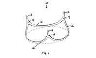
ここで図1を参照すると、大動脈弁の修復に有用な楕円形の弁輪内装着フレームの実施形態の斜視図が示され、一般的に番号10で表わされている。楕円形の弁輪内装着フレーム10は大動脈弁の弁輪内に挿置され、自己大動脈弁の再建をもたらす。
Referring now to FIG. 1, a perspective view of an embodiment of an elliptical intra-annular mounting frame useful for aortic valve repair is shown, generally designated by the numeral 10. The oval
楕円形の弁輪内装着フレーム10は複数の湾曲12、相互接続点14、およびポスト16を含む。一般的に、湾曲12は弁輪尖の形状と一致し、相互接続点14およびポスト16は交連下領域の形状と一致する。湾曲12は、大動脈弁の尖の三次元形状に対応するように楕円形の弁輪内装着フレーム10の複数の平面内でカーブする。参考として、水平面は、各湾曲12が水平面に接触しながら楕円形の弁輪内装着フレーム10が載置される平面と定義される。垂直面は、水平面と直角に交差しかつ楕円形の弁輪内装着フレーム10を垂直に貫通する平面と定義される。湾曲12は水平および垂直両方の面内でカーブすることがあり、かつ/または1つ以上の他の平面内でカーブすることがある。一般的に湾曲12は大動脈壁に接触し、大動脈弁尖に対する支持および整列をもたらす。相互接続点14およびポスト16は大動脈弁の交連に対する支持をもたらす。特に、相互接続点14およびポスト16は隣接する尖の間の三次元形状に緊密に合致し、交連の近くに位置し、こうして尖の適切な接合の回復を支持かつ支援するように設計される。相互接続点14はポスト16に向かって連続的に細くなり、こうして交連につながる隣接する尖の間の狭まる空間内に嵌合する。したがって、相互接続点14およびポスト16は交連の真下までこの尖間空間内に支持をもたらす。
The elliptical
次に図2を参照すると、図1の楕円形の弁輪内装着フレーム10の正面図が示されている。再び、楕円形の弁輪内装着フレーム10は複数の湾曲12、相互接続点14、およびポスト16を含む。
Referring now to FIG. 2, a front view of the elliptical
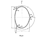
次に図3を参照すると、楕円形の弁輪内装着フレーム10の上面図が示されている。再び、楕円形の弁輪内装着フレーム10は複数の湾曲12、相互接続点14、およびポスト16を含む。図3に示す通り、楕円形の弁輪内装着フレーム10の基部は一般的に、「D」で表わされる長軸および「A」で表わされる短軸を持つ楕円形を画定する。図3に示す楕円形の弁輪内装着フレーム10の実施形態では、楕円形の短軸に対する長軸の比は約1.5:1であるが、楕円形の弁輪内装着フレームの他の実施形態(図示せず)では、楕円形の短軸に対する長軸の比は一般的に約1.7:1または1.8:1から約1.1:1または1.2:1の間で変化することができる。加えて、図3に示す楕円形の弁輪内装着フレーム10の実施形態におけるポスト16間の外周距離(楕円形の周囲の距離)は略均等(対称;外周または周囲の約33%)であるが、楕円形の弁輪内装着フレームの他の実施形態(例えば図5参照)では、ポスト16間の外周距離は異なることができる。修復しようとする大動脈弁の特定の形状に応じて、例えばポスト16間の外周距離のうちの2つは略均等とすることができるが、第3の外周距離は他の2つとは異なることができ、あるいは3つの外周距離全部が互いに異なることができる。こうして、現在記載する楕円形の弁輪内装着フレームを用いて、非対称な大動脈弁の形状を修復することができる。
Referring now to FIG. 3, a top view of the elliptical
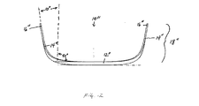
次に図4を参照すると、楕円形の弁輪内装着フレーム10の側面図が示されている。再び、楕円形の弁輪内装着フレーム10は複数の湾曲12、相互接続点14、およびポスト16を含む。図4に示す楕円形の弁輪内装着フレーム10の実施形態では、相互接続点14、ポスト16、および2つの湾曲12の上部を備えた楕円形の弁輪内装着フレーム10の3つの縁部18は、楕円形の弁輪内装着フレームの垂直面から外側に約10°広がっている。しかし、楕円形の弁輪内装着フレームの他の実施形態(図示せず)では、3つの縁部18は、楕円形の弁輪内装着フレームの垂直面から外側に約1°程度から約30°程度の間広がることができる。加えて、図4に示す楕円形の弁輪内装着フレームの実施形態では、3つの縁部18は各々垂直面から等しい角度に外側に広がっているが、追加の実施形態(図示せず)では、修復しようとする大動脈弁の特定の形状に応じて、3つの縁部18は垂直面から異なる角度で外側に広がることができ、例えば縁部18のうちの2つは垂直面から等しい角度で外側に広がることができる一方、第3縁部18は垂直面から他の2つの縁部18とは異なる角度で外側に広がることができ、あるいは3つの縁部18が全部、垂直面とは異なる角度で外側に広がることができる。
Referring now to FIG. 4, a side view of the elliptical
大動脈弁の様々な解剖学的変化を考慮して様々な配向および形状の湾曲を利用することができる。図1ないし図4で上に詳述した通り、ほとんどの実施形態で、ほとんどの大動脈弁は等しい大きさの3つの尖を有するので、湾曲は互いにかなり対称的である。しかし、追加の実施形態では、一部の患者は非対称な洞を持つ大動脈弁を有するので、楕円形の弁輪内装着フレームは非対称な設計に製造することができる。変形は、1つの湾曲の長さが他の2つの湾曲の長さより約20%大きいか、1つの湾曲の長さが他の湾曲の長さより20%小さい変形、または各湾曲の長さが異なる大きさを有する変形を持つ、楕円形の弁輪内装着フレームを含むことがあり得る。加えて、一部の患者は2つの尖だけを有する(二尖)大動脈弁を有するので、2つの湾曲および2つの相互接続点を持つ二尖楕円形の弁輪内装着フレームを製造することができる。かかる非対称でかつ二尖楕円形の弁輪内装着フレームの例が、以下に詳述される。 Various orientations and shapes of curvature can be utilized to account for various anatomical changes of the aortic valve. As detailed above in FIGS. 1-4, in most embodiments, most aortic valves have three cusps of equal size so that the curves are fairly symmetrical with each other. However, in additional embodiments, some patients have an aortic valve with an asymmetrical sinus so that the oval intra-annular mounting frame can be manufactured in an asymmetric design. The deformation is one in which the length of one curve is approximately 20% greater than the length of the other two curves, or one curve length is 20% less than the length of the other curve, or the length of each curve is different It may include an elliptical intra-annular mounting frame with a deformation having a size. In addition, because some patients have an aortic valve with only two cusps (bicuspid), it is possible to produce a bicuspid elliptical intra-annular mounting frame with two curves and two interconnection points it can. An example of such an asymmetric and bicuspid elliptical intra-annular mounting frame is described in detail below.
次に図5を参照すると、大動脈弁の修復に有用な非対称な楕円形の弁輪内装着フレームの実施形態の斜視図が示され、一般的に番号10′で表わされている。非対称な楕円形の弁輪内装着フレーム10′は大動脈弁の弁輪内に挿置され、非対称な洞を有する自己大動脈弁の再建をもたらす。非対称な楕円形の弁輪内装着フレーム10′は複数の湾曲12′、相互接続点14′、およびポスト16′を含む。図1ないし図4で上に詳述した対称な楕円形の弁輪内装着フレーム10の場合と同様に、湾曲12′は弁輪尖の形状と一致し、相互接続点14′およびポスト16′は交連下領域の形状と一致する。湾曲12′は、非対称な大動脈弁の尖の三次元形状に対応するように、非対称な楕円形の弁輪内装着フレーム10′の複数の平面内でカーブする。参考として、水平面は、各湾曲12′が水平面に接触しながら非対称な楕円形の弁輪内装着フレーム10′が載置される平面と定義される。垂直面は、水平面と直角に交差しかつ非対称な楕円形の弁輪内装着フレーム10′を垂直に貫通する平面と定義される。湾曲12′は水平および垂直両方の面内でカーブすることがあり、かつ/または1つ以上の他の平面内でカーブすることがある。一般的に湾曲12′は大動脈壁に接触し、大動脈弁尖に対する支持および整列をもたらす。相互接続点14′およびポスト16′は大動脈弁の交連に対する支持をもたらす。特に、相互接続点14′およびポスト16′は隣接する尖の間の三次元形状に緊密に合致し、交連の近くに位置し、こうして尖の適切な接合の回復を支持かつ支援するように設計される。相互接続点14′はポスト16′に向かって連続的に細くなり、こうして交連につながる隣接する尖の間の狭まる空間内に嵌合する。したがって、相互接続点14′およびポスト16′は交連の真下までこの尖間空間内に支持をもたらす。
Referring now to FIG. 5, a perspective view of an embodiment of an asymmetric elliptical intra-annular mounting frame useful for aortic valve repair is shown, generally designated 10 '. An asymmetric elliptical intra-annular mounting frame 10 'is inserted into the annulus of the aortic valve, resulting in the reconstruction of a self-aortic valve having an asymmetric sinus. The asymmetric elliptical intra-annular mounting frame 10 'includes a plurality of
次に図6を参照すると、図5の非対称な楕円形の弁輪内装着フレーム10′の正面図が示されている。再び非対称な楕円形の弁輪内装着フレーム10′は複数の湾曲12′、相互接続点14′、およびポスト16′を含む。
Referring now to FIG. 6, a front view of the asymmetric elliptical intra-annular mounting frame 10 'of FIG. 5 is shown. The asymmetric elliptical intra-annular mounting frame 10 'includes a plurality of
次に図7を参照すると、非対称な楕円形の弁輪内装着フレーム10′の上面図が示されている。再び、非対称な楕円形の弁輪内装着フレーム10′は複数の湾曲12′、相互接続点14′、およびポスト16′を含む。図7に示す通り、非対称な楕円形の弁輪内装着フレーム10′の基部は一般的に、「D」で表わされる長軸および「A」で表わされる短軸を持つ楕円形を画定する。図7に示す非対称な楕円形の弁輪内装着フレーム10′の実施形態では、楕円形の短軸に対する長軸の比は約1.5:1であるが、楕円形の弁輪内装着フレームの他の実施形態(図示せず)では、楕円形の短軸に対する長軸の比は一般的に約1.7:1または1.8:1から約1.1:1または1.2:1の間で変化することができる。加えて、図7に示す非対称な楕円形の弁輪内装着フレーム10′の実施形態におけるポスト16′間の外周距離(楕円形の周囲の距離)は各々異なる(外周または周囲の大体28%、33%、および39%)が、修復しようとする非対称な大動脈弁の特定の形状に応じて、非対称な楕円形の弁輪内装着フレームの他の実施形態(図示せず)では、ポスト16′間の外周距離のうちの2つは略均等とすることができる一方、第3の外周距離は他の2つと異なることができる。こうして、現在記載する非対称な楕円形の弁輪内装着フレームを用いて、全ての非対称な大動脈弁の形状を修復することができる。
Referring now to FIG. 7, a top view of an asymmetric elliptical intra-annular mounting frame 10 'is shown. Again, the asymmetric elliptical intra-annular mounting frame 10 'includes a plurality of
次に図8を参照すると、非対称な楕円形の弁輪内装着フレーム10′の側面図が示されている。再び、非対称な楕円形の弁輪内装着フレーム10′は複数の湾曲12′、相互接続点14′、およびポスト16′を含む。図8に示す非対称な楕円形の弁輪内装着フレーム10′の実施形態では、相互接続点14′、ポスト16′、および湾曲12′の上部を備えた非対称な楕円形の弁輪内装着フレーム10′の3つの縁部18′は、非対称な楕円形の弁輪内装着フレーム10′の垂直面から外側に約10°広がっている。しかし、非対称な楕円形の弁輪内装着フレームの他の実施形態(図示せず)では、3つの縁部18′は楕円形の弁輪内装着フレームの垂直面から外側に約1°程度から約30°程度の間広がることができる。図8に示す非対称な楕円形の弁輪内装着フレーム10′の実施形態では、3つの縁部18′は各々、垂直面から外側に等しい角度(約10°)広がっているが、追加の実施形態(図示せず)では、3つの縁部18′は垂直面から異なる角度外側に広がることができ、修復しようとする非対称な大動脈弁の特定の形状に応じて、例えば縁部18′のうちの2つは、垂直面から外側に等しい角度広がることができる一方、第3縁部18′は垂直面から外側に他の2つの縁部18′とは異なる角度広がることができ、あるいは3つの縁部18′が全部、垂直面とは異なる角度で外側に広がることができる。
Referring now to FIG. 8, a side view of an asymmetric elliptical intra-annular mounting frame 10 'is shown. Again, the asymmetric elliptical intra-annular mounting frame 10 'includes a plurality of
次に図9を参照すると、大動脈弁の修復に有用な楕円形の二尖弁輪内装着フレームの実施形態の斜視図が示され、一般的に番号10″で表わされている。楕円形の二尖弁輪内装着フレーム10″は大動脈弁の弁輪内に挿置され、2つだけの洞を有する自己大動脈弁の再建をもたらす。楕円形の二尖弁輪内装着フレーム10″は、2つの湾曲12″、相互接続点14″、およびポスト16″を含む。図1ないし図4で上に詳述した対称的な楕円形の弁輪内装着フレーム10の場合と同様に、湾曲12″は弁輪尖の形状と一致し、相互接続点14″およびポスト16″は交連下領域の形状と一致する。湾曲12″は、二尖大動脈弁の2つの尖の三次元形状に対応するように、楕円形の二尖弁輪内装着フレーム10″の複数の平面内でカーブする。参考として、水平面は、各湾曲12″が水平面に接触しながら楕円形の二尖弁輪内装着フレーム10″が載置される平面と定義される。垂直面は、水平面と直角に交差しかつ楕円形の二尖弁輪内装着フレーム10″を垂直に貫通する平面と定義される。湾曲12″は水平および垂直両方の面内でカーブすることがあり、かつ/または1つ以上の他の平面内でカーブすることがある。一般的に湾曲12″は大動脈壁に接触し、大動脈弁尖に対する支持および整列をもたらす。相互接続点14″およびポスト16″は大動脈弁の交連に対する支持をもたらす。特に、相互接続点14″およびポスト16″は隣接する尖の間の三次元形状に緊密に合致し、交連の近くに位置し、こうして尖の適切な接合の回復を支持かつ支援するように設計される。相互接続点14″はポスト16″に向かって連続的に細くなり、こうして交連につながる隣接する尖の間の狭まる空間内に嵌合する。したがって、相互接続点14″およびポスト16″は交連の真下までこの尖間空間内に支持をもたらす。
Referring now to FIG. 9, a perspective view of an embodiment of an oval bicuspid annulus mounting frame useful for aortic valve repair is shown, generally designated 10 ″. The bicuspid
次に図10を参照すると、楕円形の二尖弁輪内装着フレーム10″の正面図が示されている。楕円形の二尖弁輪内装着フレーム10″は2つの湾曲12″、相互接続点14″、およびポスト16″を含む。
Referring now to FIG. 10, a front view of an elliptical bicuspid
次に図11を参照すると、楕円形の二尖弁輪内装着フレーム10″の上面図が示されている。再び、楕円形の二尖弁輪内装着フレーム10″は2つの湾曲12″、相互接続点14″、およびポスト16″を含む。図11に示す通り、楕円形の二尖弁輪内装着フレーム10″の基部は一般的に、「D」で表わされる長軸および「A」で表わされる短軸を持つ楕円形を画定する。図11に示す楕円形の二尖弁輪内装着フレーム10″の実施形態では、楕円形の短軸に対する長軸の比は約1.5:1であるが、楕円形の二尖弁輪内装着フレームの他の実施形態(図示せず)では、楕円形の短軸に対する長軸の比は一般的に約1.7:1または1.8:1から約1.1:1または1.2:1の間で変化することができる。加えて、図11に示す楕円形の二尖弁輪内装着フレーム10″の実施形態におけるポスト16″間の外周距離(楕円形の周囲の距離)は略均等(対称;外周の約50%)であるが、楕円形の二尖弁輪内装着フレームの他の実施形態(図示せず)では、ポスト16″間の外周距離は異なることができ、修復しようとする二尖大動脈弁の特定の形状に応じて、例えば一方の外周距離を外周の約75%、他方の外周距離を外周の約25%とし、一方の外周距離を外周の約70%、他方の外周距離を外周の約30%とし、一方の外周距離を外周の約65%、他方の外周距離を外周の約35%とし、一方の外周距離を外周の約60%、他方の外周距離を外周の約40%とし、一方の外周距離を外周の約55%、他方の外周距離を外周の約45%などとすることができる。こうして、現在記載する非対称な楕円形の二尖弁輪内装着フレームを用いて、全ての非対称な二尖大動脈弁形状を修復することができる。
Referring now to FIG. 11, a top view of an elliptical bicuspid
次に図12を参照すると、楕円形の二尖弁輪内装着フレーム10″の側面図が示されている。再び、楕円形の二尖弁輪内装着フレーム10″は2つの湾曲12″、相互接続点14″、およびポスト16″を含む。図12に示す楕円形の二尖弁輪内装着フレーム10″の実施形態では、相互接続点14″、ポスト16″、および2つの湾曲12″の上部を備えた楕円形の二尖弁輪内装着フレーム10″の2つの縁部18″は、楕円形の二尖弁輪内装着フレームの垂直面から外側に約10°広がる。しかし、楕円形の二尖弁輪内装着フレームの他の実施形態(図示せず)では、2つの縁部18″は弁輪内装着フレームの垂直面から外側に約1°程度から約30°程度の間広がることができる。図12に示す楕円形の二尖弁輪内装着フレーム10″の実施形態では、2つの縁部18″は各々垂直面から外側に等しい角度広がることができるが、追加の実施形態(図示せず)では、2つの縁部18″は、修復しようとする二尖大動脈弁の特定の形状に応じて、垂直面から外側に異なる角度に広がることができる。
Referring now to FIG. 12, a side view of an oval bicuspid
最も一般的に、楕円形の弁輪内装着フレームの長軸は長さが約10ミリメートルから約35ミリメートル程度であり、楕円形の弁輪内装着フレームの短軸は長さが約8ミリメートルから約25ミリメートル程度であり、それらの間の種々の異なる大きさのフレームは、患者の要求に密接に近づくように可能な選択肢の勾配を形成する。しかし、大動脈根瘤またはMarian症候群の患者に利用するために、より大きいサイズの楕円形の弁輪内装着フレームを製造することができる。さらに、湾曲の基部からポストの先端までを測定した楕円形の弁輪内装着フレームの高さは様々に異なってよいが、一般的には約8ミリメートルから約15ミリメートル程度の範囲である。 Most commonly, the major axis of the elliptical intra-annular mounting frame is about 10 millimeters to about 35 millimeters in length, and the minor axis of the elliptical intra-annular mounting frame is about 8 millimeters in length. The various different sized frames between them, on the order of about 25 millimeters, form a gradient of possible choices to closely approach the patient's requirements. However, larger sized elliptical intra-annular mounting frames can be manufactured for use in patients with aortic root aneurysms or Marian syndrome. Further, the height of the elliptical intra-annular mounting frame measured from the base of the curve to the tip of the post may vary, but generally ranges from about 8 millimeters to about 15 millimeters.
楕円形の弁輪内装着フレームは、大きく拡張した大動脈根から生じる潜在的に高い張力にもかかわらず無傷の状態を維持する金属、プラスチック、熱可塑性プラスチック、高分子化合物、樹脂、または他の材料から構成することができる。楕円形の弁輪内装着フレームは、中実金属線、中実プラスチック、または大動脈弁内に移植した後、縫合のための優れた手掛かりをもたらすように穿孔した帯状の金属もしくはプラスチックから構成することができる。穿孔は設置方法に応じて異なってよいが、略均等な形状の弁輪領域では、設定された数および位置の縫合用の穿孔を楕円形の弁輪内装着フレームに形成し、マークを付けることができる。特定の実施形態では、楕円形の弁輪内装着フレームはGORE‐TEX(登録商標)コーティングを含むことができる。さらなる実施形態では、楕円形の弁輪内装着フレームは、DACRON(登録商標)クロースの名称で販売されているポリエチレンテレフタレートを含め、しかしそれに限らず、様々な高分子化合物または高分子樹脂で被覆またはコーティングすることができる。代替的に、楕円形の弁輪内装着フレームは、グルタルアルデヒド固定されたウシの心膜で被覆することができ、それは、特定の実施形態では、左心室の流出路における高い血流速度のため、布の被覆により患者がおそらく溶血を起こしやすくなることがあり得るので、有用であり得る。 An oval intra-annular mounting frame is a metal, plastic, thermoplastic, polymeric compound, resin, or other material that remains intact despite the potentially high tension arising from a large dilated aortic root It can consist of The oval intra-annular mounting frame shall consist of solid metal wire, solid plastic, or a band of metal or plastic drilled to provide a good clue for suturing after implantation into an aortic valve Can do. Perforations may vary depending on the method of installation, but in a substantially uniform annulus area, a set number and position of perforations for stitching should be formed and marked on the oval intraannular mounting frame Can do. In certain embodiments, the oval intra-annular mounting frame may include a GORE-TEX® coating. In further embodiments, the oval intra-annular mounting frame may be coated or coated with various polymeric compounds or polymeric resins including, but not limited to, polyethylene terephthalate sold under the name DACRON® Close. Can be coated. Alternatively, the oval intra-annular mounting frame can be coated with glutaraldehyde-fixed bovine pericardium, which in certain embodiments, due to high blood flow velocity in the left ventricular outflow tract This can be useful because the covering of the fabric may possibly make the patient more susceptible to hemolysis.
楕円形の弁輪内装着フレームの多くの利点の1つは、必要なフレームの大きさを術前に容易に決定することができることである。患者のための楕円形の弁輪内装着フレームを作製するのに必要な測定値を決定するために、非侵襲的に磁気共鳴撮像法(MRI)、心エコー検査法、またはコンピュータ断層撮影(CT)血管造影法のような撮像技術を使用することができる。さらなる実施形態では、MRI機械またはCT血管造影機械および関連制御装置をはじめとする撮像装置は、患者の大動脈弁の大きさを自動的に測定し、患者の大動脈弁の能力を回復するために必要な、適切な大きさの楕円形の弁輪内装着フレームを出力する、楕円形の弁輪内装着フレームのシステムパラメータならびに数学的モデルおよび記述を含むことができる。追加的データ出力は、能力を回復するための種々の大きさの楕円形の弁輪内装着フレームおよび各々の異なるフレームが移植後にもたらす効果の表示を含む。 One of the many advantages of an elliptical intra-annular mounting frame is that the required frame size can be easily determined prior to surgery. Non-invasively magnetic resonance imaging (MRI), echocardiography, or computed tomography (CT) to determine the measurements required to create an oval intra-annular mounting frame for the patient ) Imaging techniques such as angiography can be used. In a further embodiment, an imaging device, including an MRI machine or CT angiography machine and associated control device, is required to automatically measure the size of the patient's aortic valve and restore the patient's aortic valve performance. System parameters and mathematical models and descriptions of the elliptical intra-annular mounting frame that output an appropriately sized elliptical intra-annular mounting frame. Additional data output includes various sizes of elliptical intra-annular mounting frames to restore performance and an indication of the effect each different frame will have after implantation.
特定の実施形態では、現在記載する楕円形の弁輪内装着フレームは、縫合糸を通すための穿孔を湾曲およびポストに有することができる。例えば縫合糸は水平マットレス縫合糸とすることができ、その場合糸は大動脈弁弁輪の下の大動脈壁内に通過することができる。1つの特定の構成では、縫合糸は尖の下で大動脈壁の奥深くに通過することができ、尖および交連に密接に対応する楕円形の弁輪内装着フレームを大動脈弁の弁輪内に直接挿置することを可能にする。任意選択的に、1つの尖につき3つ、および1つの交連につき1つの水平マットレス縫合糸を利用することができ、楕円形の弁輪内装着フレームを移植するために合計で12の縫合糸が使用される。当業者は、楕円形の弁輪内装着フレームを大動脈弁の弁輪内に配置しかつ取り付けるために、より少ないかより多い縫合糸のみならず、当業界で公知の他の取付け技術も利用することができることを理解されるであろう。大動脈組織の断裂の可能性を防ぐために、大動脈弁の上からマットレス縫合糸の上に綿撒糸を配置することができる。綿撒糸はTEFLON(登録商標)フェルト綿撒糸とすることができ、他の実施形態では、綿撒糸ではなく、DACRON(登録商標)のような布片または断片または帯状の織物をマットレス縫合糸と共に利用することができる。綿撒糸は一般的に小さいので、大動脈弁弁葉の可動性を阻害しない。 In certain embodiments, the oval intra-annular mounting frame described herein can have perforations in the curves and posts for threading sutures. For example, the suture can be a horizontal mattress suture, in which case the thread can pass into the aortic wall under the aortic valve annulus. In one particular configuration, the suture can pass under the apex and deep into the aortic wall, with an oval intra-annular mounting frame that closely corresponds to the apex and commissure directly into the aortic valve annulus. Allows to be inserted. Optionally, three horizontal mattress sutures per tip and one commissure can be utilized, for a total of twelve sutures to implant an oval intra-annular mounting frame. used. Those skilled in the art will utilize not only fewer or more sutures, but also other attachment techniques known in the art to place and attach an elliptical intra-annular mounting frame within the annulus of the aortic valve. It will be understood that it can. A pledget can be placed over the mattress suture over the aortic valve to prevent the possibility of aortic tissue rupture. The pledget can be a TEFLON® felt pledget, and in other embodiments, a piece of cloth or a piece of strip or strip-like fabric, such as DACRON®, is mattress stitched instead of pledget. Can be used with yarn. Since pledgets are generally small, they do not interfere with the mobility of the aortic valve leaflets.
代替的実施形態では、楕円形の弁輪内装着フレームを設置するために、弁輪の上に、縫合糸を挿通することのできる支持アークを使用することができる。そのような支持アークは、交連と同様に大動脈壁への尖の取付けの湾曲および形状に対応する、楕円形の弁輪内装着フレームの形状と略同様の形状を持つ3つの湾曲を含み、その結果、大動脈弁の弁輪は楕円形の弁輪内装着フレームと支持アークとの間に「狭持」される。縫合糸は楕円形の弁輪内装着フレームの穿孔を介し、大動脈壁を介して尖の上の支持アークに延び、支持アークの穿孔をも介して取り付ける。追加の実施形態では、縫合糸は支持アークの周りに延び、あるいは当業界で公知の他の方法を用いて取り付けることができる。 In an alternative embodiment, a support arc through which a suture can be inserted can be used over the annulus to install an elliptical intra-annular mounting frame. Such a support arc includes three curves having a shape substantially similar to the shape of an elliptical intra-annular mounting frame, corresponding to the curve and shape of the apex attachment to the aortic wall as well as the commissures. As a result, the annulus of the aortic valve is “sandwiched” between the elliptical intra-annular mounting frame and the support arc. The suture extends through the oval intra-annular mounting frame, extends through the aortic wall to the support arc above the apex, and is also attached through the support arc. In additional embodiments, the suture can extend around the support arc or be attached using other methods known in the art.
記載した楕円形の弁輪内装着フレームおよび楕円形の弁輪内装着フレームの大きさを決定しかつ移植する関連方法は、他の病態にも適用することができる。大動脈根瘤では、楕円形の弁輪内装着フレームは、現行手技の場合のように大がかりな外側からの切開の必要なく、大動脈の内側から弁葉温存根置換を実行することを可能にする。楕円形の弁輪内装着フレームと共に無孔DACRON(登録商標)グラフトを、バルサルバの洞と形状が一致するようにグラフトの近位面を波打たせ広げた後、利用することができる。グラフトの大きさは、遠位大動脈の直径についても考慮しながら、楕円形の弁輪内装着フレームの大きさに適合するように選択することができる。次いで、ボタンとして、または封入技術により、冠動脈をグラフトの横に吻合することができる。この簡単な方法を用いて、大動脈弁の弁輪の大きさおよび形状が決定され、自己大動脈弁は修復かつ保存され、現行の技術よりずっと少ない切開および難度により、動脈根瘤疾患に対し根および上行大動脈全体を置換することができる。 The described oval intra-annular mounting frame and related methods of determining and implanting the oval intra-annular mounting frame can be applied to other pathologies. In an aortic root aneurysm, the oval intra-annular mounting frame allows performing leaflet-preserving root replacement from the inside of the aorta without the need for extensive outside incisions as in current procedures. A non-porous DACRON® graft with an elliptical intra-annular mounting frame can be utilized after the proximal surface of the graft is waved and widened to conform to the Valsalva sinus. The size of the graft can be selected to match the size of the oval intra-annular mounting frame, also taking into account the diameter of the distal aorta. The coronary artery can then be anastomosed next to the graft as a button or by an encapsulation technique. Using this simple method, the annulus size and shape of the aortic valve is determined, the self-aortic valve is repaired and preserved, and the root and ascending against arterial root disease with much less incision and difficulty than current techniques The entire aorta can be replaced.
他の病態も記載した楕円形の弁輪内装着フレームを用いて対処することができる。超音波創面切除を補助的に使用して、カルシウムの針状体を除去することができ、弁葉の一部分を切除して、グルタルアルデヒド固定した自己心膜に置換することができる。この概念は、大動脈弁の単一または複数の尖置換の選択肢をも含む。再配向を通して根の形状を決定し、かつ潜在的にそれをわずかに縮小する方法により、楕円形の弁輪内装着フレームがわずかな不足を補償して、複雑な修復に取り組むことができる。1つの尖が重症または逸脱している場合、例えば尖を、(楕円形の弁輪内装着フレームおよび自己尖の大きさに適合する適切な大きさおよび形状の)グルタルアルデヒド固定された自己(または特定の場合、ウシの)心膜尖に置換することができる。楕円形の弁輪内装着フレームがアークおよび人工弁葉への取付具として働き、人工尖を楕円形の弁輪内装着フレームの上のアークに取り付けることができる。患者の他の弁組織は温存することができ、完全に適格な弁が達成され、その場合、それは3分の2が自己組織である。心膜弁葉組織は、石灰化を防止するための最新技術により処理することができるが、人工弁葉が術後に後で運動不能になった場合、それは依然として他の弁葉のための接合バフルとして働くことができ、全異種グラフト置換術で生じうるように、おそらく追加の手術を必要としない。 Other pathological conditions can be addressed using an oval intra-annular mounting frame. Ultrasonic debridement can be used to remove calcium needles, and a portion of the leaflets can be excised and replaced with glutaraldehyde-fixed autologous pericardium. This concept also includes single or multiple apex replacement options for the aortic valve. By determining the shape of the root through reorientation and potentially slightly reducing it, the oval intra-annular mounting frame can compensate for the slight deficiency and address complex repairs. If one cusp is severe or deviating, for example, the cusp is a glutaraldehyde-fixed self (or of an appropriate size and shape that fits the size of the oval intra-annular mounting frame and the self-cusp) (or In certain cases, a bovine (pericardial) apex can be substituted. The elliptical intra-annular mounting frame serves as an attachment to the arc and the prosthetic leaflet, and the artificial cusp can be attached to the arc on the elliptical intra-annular mounting frame. The patient's other valve tissue can be preserved and a fully qualified valve is achieved, in which case two thirds are self-organized. Pericardial leaflet tissue can be processed with state-of-the-art technology to prevent calcification, but if the prosthetic leaflets become inoperable later after surgery, it still remains a joint for other leaflets It can act as a baffle and probably does not require additional surgery, as can occur with all-graft replacement.
以下の実施例は、本発明の好適な実施形態を実証するために含まれる。以下の実施例に開示する技術が発明の実施においてよく機能することが本発明者らによって明らかになった技術を代表するものであり、したがって発明の実施の好適な形態を構成するとみなすことができることを、当業者は理解されたい。しかし、当業者は、本開示に照らして、開示する特定の実施形態に多くの変化を施しても、依然として発明の精神および範囲から逸脱することなく類似または同様の結果を得ることができることを理解されたい。本発明は、発明の個々の態様の単なる例証として意図された、本書に記載する特定の実施形態によって範囲を制限されず、機能的に同等の方法および構成要素は発明の範囲内である。実際、本書に図示しかつ記載したものに加えて、発明の種々の変形例が、当業者には上記の説明から明らかになるであろう。そのような変形例は、添付する特許請求の範囲に該当することを意図している。 The following examples are included to demonstrate preferred embodiments of the invention. The technology disclosed in the following examples is representative of the technology that has been clarified by the present inventors to function well in the practice of the invention, and therefore can be considered to constitute a preferred embodiment of the invention. Should be understood by those skilled in the art. However, one of ordinary skill in the art appreciates that, in light of the present disclosure, many changes may be made in the particular embodiments disclosed and still obtain similar or similar results without departing from the spirit and scope of the invention. I want to be. The present invention is not to be limited in scope by the specific embodiments described herein, which are intended as merely illustrative of individual aspects of the invention, and functionally equivalent methods and components are within the scope of the invention. Indeed, various modifications of the invention, in addition to those shown and described herein, will be apparent to those skilled in the art from the foregoing description. Such modifications are intended to fall within the scope of the appended claims.
実施例1
発明者らは、健康なヒトの大動脈弁の高解像度マルチスライスコンピュータ断層撮影(CT)血管造影図を入手して解析した。1mmの軸線方向スライスを用いて、Mathematicaで10個の正常な大動脈根のCT血管造影図から弁構造物のx、y、およびz座標を生成した。弁葉および洞の座標の三次元最小二乗回帰を使用して、半球モデルと楕円モデルとを比較した。全ての根構造物の形状および寸法を評価した。
Example 1
The inventors obtained and analyzed high resolution multi-slice computed tomography (CT) angiograms of healthy human aortic valves. The x, y, and z coordinates of the valve structure were generated from CT angiograms of 10 normal aortic roots with Mathematica using a 1 mm axial slice. A hemispherical model and an elliptical model were compared using 3D least squares regression of leaflet and sinus coordinates. The shape and dimensions of all root structures were evaluated.
正常な弁の形状は、円筒内に嵌め込まれた3つの半球として表わすことができる。しかし、寸法的適合は楕円体の形状を用いる方が良好であり、弁葉の高さは半球によって予測されたより高かった。弁葉/洞の水平方向の外周は、かなり円形に近かった(平均短軸‐長軸比=0.82〜0.87)。弁の基部は全く楕円形であり(短軸‐長軸比=0.65)、この形状は垂直方向に延在した。左冠動脈(LC)尖と無冠動脈(NC)尖との間の交連は、右冠動脈(RC)尖の中心と対向して、基部の短径と外周との後接合部に位置する。LC、NC、およびRCの弁葉/洞楕円体の中心は、弁の中心の方向に移動した(それぞれの平均微小移動すなわちアルファ=0.24、0.32、および0.09)。交連は5〜10度外側に広がり、RC尖は最大であった(表1)。

さらに、交連下領域の調査から、交連が弁の中心から約5〜10度外側に広がったことが示された。したがって、装着フレームは、本書および以下に記載するように、ポストが狭まりかつ張り出し、楕円形の断面を持つように設計された。 In addition, investigation of the subcommissural region showed that the commissure spread about 5-10 degrees outward from the center of the valve. Therefore, the mounting frame was designed with the posts narrowed and overhanging and having an oval cross section, as described herein and below.
実施例2
1.5の軸比(長軸/短軸または0.66の短軸/長軸の軸比)の楕円形の断面および10°外側に広がったポストを持つ現在記載した弁輪内装着フレームを子ウシで試験し、以下の詳述する通り有望な結果を得た。
Example 2
The presently described intra-annular mounting frame having an elliptical cross section with an axial ratio of 1.5 (major axis / minor axis ratio or 0.66 minor axis / major axis ratio) and a post extending 10 ° outward. Tested on calves, promising results were obtained as detailed below.
Texas Heart Instituteで生存研究のために装着フレームを10頭の子ウシに移植した。子ウシを移植モデルとして使用したのは、子ウシがヒトに近い大きさの弁を持ち、臨床的にヒトに使用されるであろう装置に対する良好な対応性をもたらすからであった。修復された弁の心エコー解析は、優れた弁葉接合、正常な弁葉開口、無漏出、および不撹乱層流を示した。CT血流造影法は、拡張期の正常な楕円形の弁葉の形状および接合、および収縮期の弁葉の良好な開口を示した。これらの結果は根血管造影法を用いて確認された。 The mounting frame was transplanted into 10 calves for survival studies at the Texas Heart Institute. The calf was used as a transplant model because the calf has a valve of a size close to that of a human and provides good compatibility with devices that would be clinically used by humans. Echocardiographic analysis of the repaired valve showed excellent leaflet joints, normal leaflet opening, no leakage, and undisturbed laminar flow. CT angiography showed a normal oval leaflet shape and junction in diastole and a good opening in the systolic leaflet. These results were confirmed using root angiography.
死体解剖で、加圧水下で内視鏡検査を実行し、全ての子ウシで、弁葉が優れた垂直性をもってよく位置合せされており、接合の問題が無く、すなわち弁葉は正中線上で交差し、綿撒糸は充分に内皮化していることが示された。 Carcass dissection, endoscopy under pressurized water, and in all calves, the leaflets are well aligned with excellent verticality and there is no joint problem, ie the leaflets intersect on the midline It was shown that the pledget was fully endothelialized.
現在記載する装着フレームは現在、臨床試験を受けることが計画されている。 The mounting frame currently described is currently planned to undergo clinical trials.
本書に開示しかつ請求する構成および/または方法は全て、本開示に照らして過度の実験なしに作成しかつ実行することができる。本発明の構成および方法を好適な実施形態に関して記載したが、発明の概念、精神、および範囲から逸脱することなく、該構成および/または方法、ならびに本書に記載する方法のステップまたは一連のステップに変化を適用することができることを、当業者は理解されるであろう。さらに詳しくは、本書に記載する作用物質を、化学的にかつ生理学的に関連する特定の作用物質に置き換えながら、同一または同様の結果を達成することができることは明らかであろう。当業者にとって明白な全てのそのような代替物および変形は、添付の特許請求の範囲に記載する発明の精神、範囲、および概念の範疇であるとみなされる。 All of the configurations and / or methods disclosed and claimed herein can be made and executed without undue experimentation in light of the present disclosure. Although the structure and method of the present invention have been described with reference to preferred embodiments, it is understood that the structure and / or method and method steps or series of steps described herein may be performed without departing from the concept, spirit, and scope of the invention. One skilled in the art will appreciate that changes can be applied. More specifically, it will be apparent that the same or similar results can be achieved while substituting the agents described herein with specific agents that are chemically and physiologically related. All such alternatives and modifications apparent to those skilled in the art are deemed to be within the spirit, scope and concept of the invention as defined by the appended claims.
Claims (12)
b)内部領域を形成するために湾曲の各々の端を相互接続する複数の点と;
c)点の各々から上向きに延びる複数のポストと
を備えた大動脈弁用の弁輪内装着フレームであって、
点、湾曲の端、およびポストが、弁輪内装着フレームの垂直面から測定して5度〜15度の角度で弁輪内装着フレームの内部領域から外側に広がる縁領域を画定し、かつ弁輪内装着フレームが、長軸および短軸を有する楕円形の形状を有し、
短軸に対する長軸の比は1.2〜1.8である、弁輪内装着フレーム。 a) a plurality of curves having ends;
b) a plurality of points interconnecting each end of the curve to form an interior region;
c) an intra-annular mounting frame for an aortic valve comprising a plurality of posts extending upward from each of the points,
The point, the end of the curve, and the post define an edge region extending outwardly from the interior region of the intra-annular mounting frame at an angle of 5 to 15 degrees as measured from the vertical plane of the intra-annular mounting frame; The in-ring mounting frame has an elliptical shape with a major axis and a minor axis;
The ratio of the major axis to the minor axis is 1 . An annulus mounting frame that is 2 to 1.8.
Applications Claiming Priority (3)
| Application Number | Priority Date | Filing Date | Title |
|---|---|---|---|
| US38857310P | 2010-09-30 | 2010-09-30 | |
| US61/388,573 | 2010-09-30 | ||
| PCT/US2011/054160 WO2012044901A2 (en) | 2010-09-30 | 2011-09-30 | Intra-annular mounting frame for aortic valve repair |
Publications (3)
| Publication Number | Publication Date |
|---|---|
| JP2013542761A JP2013542761A (en) | 2013-11-28 |
| JP2013542761A5 JP2013542761A5 (en) | 2014-11-06 |
| JP5877205B2 true JP5877205B2 (en) | 2016-03-02 |
Family
ID=44800265
Family Applications (1)
| Application Number | Title | Priority Date | Filing Date |
|---|---|---|---|
| JP2013531901A Active JP5877205B2 (en) | 2010-09-30 | 2011-09-30 | Intra-annular mounting frame for aortic valve repair |
Country Status (6)
| Country | Link |
|---|---|
| US (1) | US20120083880A1 (en) |
| EP (1) | EP2621407B1 (en) |
| JP (1) | JP5877205B2 (en) |
| CA (1) | CA2813246A1 (en) |
| ES (1) | ES2659542T3 (en) |
| WO (1) | WO2012044901A2 (en) |
Cited By (1)
| Publication number | Priority date | Publication date | Assignee | Title |
|---|---|---|---|---|
| JP2013542764A (en) * | 2010-09-30 | 2013-11-28 | バイオステイブル サイエンス アンド エンジニアリング インコーポレイテッド | Aortic valve device |
Families Citing this family (18)
| Publication number | Priority date | Publication date | Assignee | Title |
|---|---|---|---|---|
| US8163011B2 (en) | 2006-10-06 | 2012-04-24 | BioStable Science & Engineering, Inc. | Intra-annular mounting frame for aortic valve repair |
| US8579964B2 (en) | 2010-05-05 | 2013-11-12 | Neovasc Inc. | Transcatheter mitral valve prosthesis |
| US9161835B2 (en) | 2010-09-30 | 2015-10-20 | BioStable Science & Engineering, Inc. | Non-axisymmetric aortic valve devices |
| US9554897B2 (en) | 2011-04-28 | 2017-01-31 | Neovasc Tiara Inc. | Methods and apparatus for engaging a valve prosthesis with tissue |
| US9308087B2 (en) | 2011-04-28 | 2016-04-12 | Neovasc Tiara Inc. | Sequentially deployed transcatheter mitral valve prosthesis |
| US9345573B2 (en) | 2012-05-30 | 2016-05-24 | Neovasc Tiara Inc. | Methods and apparatus for loading a prosthesis onto a delivery system |
| US9681951B2 (en) | 2013-03-14 | 2017-06-20 | Edwards Lifesciences Cardiaq Llc | Prosthesis with outer skirt and anchors |
| US9572665B2 (en) | 2013-04-04 | 2017-02-21 | Neovasc Tiara Inc. | Methods and apparatus for delivering a prosthetic valve to a beating heart |
| WO2017127939A1 (en) | 2016-01-29 | 2017-08-03 | Neovasc Tiara Inc. | Prosthetic valve for avoiding obstruction of outflow |
| CN113893064A (en) | 2016-11-21 | 2022-01-07 | 内奥瓦斯克迪亚拉公司 | Methods and systems for rapid retrieval of transcatheter heart valve delivery systems |
| EP3672530A4 (en) | 2017-08-25 | 2021-04-14 | Neovasc Tiara Inc. | Sequentially deployed transcatheter mitral valve prosthesis |
| US11737872B2 (en) | 2018-11-08 | 2023-08-29 | Neovasc Tiara Inc. | Ventricular deployment of a transcatheter mitral valve prosthesis |
| JP7438236B2 (en) | 2019-04-01 | 2024-02-26 | ニオバスク ティアラ インコーポレイテッド | Controllably deployable prosthetic valve |
| EP3952792A4 (en) | 2019-04-10 | 2023-01-04 | Neovasc Tiara Inc. | Prosthetic valve with natural blood flow |
| US11779742B2 (en) | 2019-05-20 | 2023-10-10 | Neovasc Tiara Inc. | Introducer with hemostasis mechanism |
| AU2020295566B2 (en) | 2019-06-20 | 2023-07-20 | Neovasc Tiara Inc. | Low profile prosthetic mitral valve |
| CN114173713A (en) | 2019-07-15 | 2022-03-11 | 沃卡尔有限公司 | Transcatheter bioprosthetic member and support structure |
| CN111481323A (en) * | 2020-05-20 | 2020-08-04 | 中国医学科学院阜外医院 | Aortic valve shaping ring |
Family Cites Families (10)
| Publication number | Priority date | Publication date | Assignee | Title |
|---|---|---|---|---|
| US3714671A (en) * | 1970-11-30 | 1973-02-06 | Cutter Lab | Tissue-type heart valve with a graft support ring or stent |
| FR2708458B1 (en) * | 1993-08-03 | 1995-09-15 | Seguin Jacques | Prosthetic ring for cardiac surgery. |
| US5728152A (en) * | 1995-06-07 | 1998-03-17 | St. Jude Medical, Inc. | Bioresorbable heart valve support |
| JPH11514546A (en) * | 1995-11-01 | 1999-12-14 | セント ジュード メディカル,インコーポレイテッド | Bioabsorbable annuloplasty prosthesis |
| US6858039B2 (en) * | 2002-07-08 | 2005-02-22 | Edwards Lifesciences Corporation | Mitral valve annuloplasty ring having a posterior bow |
| US6805710B2 (en) * | 2001-11-13 | 2004-10-19 | Edwards Lifesciences Corporation | Mitral valve annuloplasty ring for molding left ventricle geometry |
| US20050149181A1 (en) * | 2004-01-07 | 2005-07-07 | Medtronic, Inc. | Bileaflet prosthetic valve and method of manufacture |
| US8163011B2 (en) * | 2006-10-06 | 2012-04-24 | BioStable Science & Engineering, Inc. | Intra-annular mounting frame for aortic valve repair |
| US9161835B2 (en) * | 2010-09-30 | 2015-10-20 | BioStable Science & Engineering, Inc. | Non-axisymmetric aortic valve devices |
| EP2621408B1 (en) * | 2010-09-30 | 2016-04-20 | Biostable Science&Engineering Inc. | Aortic valve devices |
-
2011
- 2011-09-30 WO PCT/US2011/054160 patent/WO2012044901A2/en active Application Filing
- 2011-09-30 JP JP2013531901A patent/JP5877205B2/en active Active
- 2011-09-30 EP EP11770003.9A patent/EP2621407B1/en active Active
- 2011-09-30 US US13/249,621 patent/US20120083880A1/en not_active Abandoned
- 2011-09-30 ES ES11770003.9T patent/ES2659542T3/en active Active
- 2011-09-30 CA CA2813246A patent/CA2813246A1/en not_active Abandoned
Cited By (1)
| Publication number | Priority date | Publication date | Assignee | Title |
|---|---|---|---|---|
| JP2013542764A (en) * | 2010-09-30 | 2013-11-28 | バイオステイブル サイエンス アンド エンジニアリング インコーポレイテッド | Aortic valve device |
Also Published As
| Publication number | Publication date |
|---|---|
| ES2659542T3 (en) | 2018-03-16 |
| US20120083880A1 (en) | 2012-04-05 |
| WO2012044901A2 (en) | 2012-04-05 |
| JP2013542761A (en) | 2013-11-28 |
| EP2621407B1 (en) | 2018-01-17 |
| CA2813246A1 (en) | 2012-04-05 |
| WO2012044901A3 (en) | 2012-07-19 |
| EP2621407A2 (en) | 2013-08-07 |
Similar Documents
| Publication | Publication Date | Title |
|---|---|---|
| JP5877205B2 (en) | Intra-annular mounting frame for aortic valve repair | |
| JP6683875B2 (en) | Artificial heart valve | |
| JP6006218B2 (en) | Aortic valve device | |
| US10327891B2 (en) | Intra-annular mounting frame for aortic valve repair | |
| US9814574B2 (en) | Non-axisymmetric aortic valve devices | |
| EA038964B1 (en) | Prosthetic cardiac valve (embodiments) | |
| US20220218479A1 (en) | Intra-annular mounting frame for aortic valve repair |
Legal Events
| Date | Code | Title | Description |
|---|---|---|---|
| A521 | Request for written amendment filed |
Free format text: JAPANESE INTERMEDIATE CODE: A523 Effective date: 20140918 |
|
| A621 | Written request for application examination |
Free format text: JAPANESE INTERMEDIATE CODE: A621 Effective date: 20140918 |
|
| A977 | Report on retrieval |
Free format text: JAPANESE INTERMEDIATE CODE: A971007 Effective date: 20150731 |
|
| A131 | Notification of reasons for refusal |
Free format text: JAPANESE INTERMEDIATE CODE: A131 Effective date: 20150811 |
|
| A601 | Written request for extension of time |
Free format text: JAPANESE INTERMEDIATE CODE: A601 Effective date: 20151110 |
|
| A521 | Request for written amendment filed |
Free format text: JAPANESE INTERMEDIATE CODE: A523 Effective date: 20151208 |
|
| TRDD | Decision of grant or rejection written | ||
| A01 | Written decision to grant a patent or to grant a registration (utility model) |
Free format text: JAPANESE INTERMEDIATE CODE: A01 Effective date: 20160105 |
|
| A61 | First payment of annual fees (during grant procedure) |
Free format text: JAPANESE INTERMEDIATE CODE: A61 Effective date: 20160125 |
|
| R150 | Certificate of patent or registration of utility model |
Ref document number: 5877205 Country of ref document: JP Free format text: JAPANESE INTERMEDIATE CODE: R150 |
|
| R250 | Receipt of annual fees |
Free format text: JAPANESE INTERMEDIATE CODE: R250 |
|
| R250 | Receipt of annual fees |
Free format text: JAPANESE INTERMEDIATE CODE: R250 |
|
| R250 | Receipt of annual fees |
Free format text: JAPANESE INTERMEDIATE CODE: R250 |
|
| R250 | Receipt of annual fees |
Free format text: JAPANESE INTERMEDIATE CODE: R250 |
|
| R250 | Receipt of annual fees |
Free format text: JAPANESE INTERMEDIATE CODE: R250 |
|
| S111 | Request for change of ownership or part of ownership |
Free format text: JAPANESE INTERMEDIATE CODE: R313113 |
|
| R350 | Written notification of registration of transfer |
Free format text: JAPANESE INTERMEDIATE CODE: R350 |