JP5876706B2 - Linear motion rolling guide unit - Google Patents
Linear motion rolling guide unit Download PDFInfo
- Publication number
- JP5876706B2 JP5876706B2 JP2011236761A JP2011236761A JP5876706B2 JP 5876706 B2 JP5876706 B2 JP 5876706B2 JP 2011236761 A JP2011236761 A JP 2011236761A JP 2011236761 A JP2011236761 A JP 2011236761A JP 5876706 B2 JP5876706 B2 JP 5876706B2
- Authority
- JP
- Japan
- Prior art keywords
- ball
- end cap
- molded body
- porous molded
- path
- Prior art date
- Legal status (The legal status is an assumption and is not a legal conclusion. Google has not performed a legal analysis and makes no representation as to the accuracy of the status listed.)
- Active
Links
Images


Classifications
-
- F—MECHANICAL ENGINEERING; LIGHTING; HEATING; WEAPONS; BLASTING
- F16—ENGINEERING ELEMENTS AND UNITS; GENERAL MEASURES FOR PRODUCING AND MAINTAINING EFFECTIVE FUNCTIONING OF MACHINES OR INSTALLATIONS; THERMAL INSULATION IN GENERAL
- F16C—SHAFTS; FLEXIBLE SHAFTS; ELEMENTS OR CRANKSHAFT MECHANISMS; ROTARY BODIES OTHER THAN GEARING ELEMENTS; BEARINGS
- F16C29/00—Bearings for parts moving only linearly
- F16C29/04—Ball or roller bearings
- F16C29/06—Ball or roller bearings in which the rolling bodies circulate partly without carrying load
- F16C29/0602—Details of the bearing body or carriage or parts thereof, e.g. methods for manufacturing or assembly
- F16C29/0609—Details of the bearing body or carriage or parts thereof, e.g. methods for manufacturing or assembly of the ends of the bearing body or carriage where the rolling elements change direction, e.g. end caps
-
- F—MECHANICAL ENGINEERING; LIGHTING; HEATING; WEAPONS; BLASTING
- F16—ENGINEERING ELEMENTS AND UNITS; GENERAL MEASURES FOR PRODUCING AND MAINTAINING EFFECTIVE FUNCTIONING OF MACHINES OR INSTALLATIONS; THERMAL INSULATION IN GENERAL
- F16C—SHAFTS; FLEXIBLE SHAFTS; ELEMENTS OR CRANKSHAFT MECHANISMS; ROTARY BODIES OTHER THAN GEARING ELEMENTS; BEARINGS
- F16C29/00—Bearings for parts moving only linearly
- F16C29/04—Ball or roller bearings
- F16C29/06—Ball or roller bearings in which the rolling bodies circulate partly without carrying load
- F16C29/0633—Ball or roller bearings in which the rolling bodies circulate partly without carrying load with a bearing body defining a U-shaped carriage, i.e. surrounding a guide rail or track on three sides
- F16C29/0635—Ball or roller bearings in which the rolling bodies circulate partly without carrying load with a bearing body defining a U-shaped carriage, i.e. surrounding a guide rail or track on three sides whereby the return paths are provided as bores in a main body of the U-shaped carriage, e.g. the main body of the U-shaped carriage is a single part with end caps provided at each end
- F16C29/0638—Ball or roller bearings in which the rolling bodies circulate partly without carrying load with a bearing body defining a U-shaped carriage, i.e. surrounding a guide rail or track on three sides whereby the return paths are provided as bores in a main body of the U-shaped carriage, e.g. the main body of the U-shaped carriage is a single part with end caps provided at each end with balls
- F16C29/064—Ball or roller bearings in which the rolling bodies circulate partly without carrying load with a bearing body defining a U-shaped carriage, i.e. surrounding a guide rail or track on three sides whereby the return paths are provided as bores in a main body of the U-shaped carriage, e.g. the main body of the U-shaped carriage is a single part with end caps provided at each end with balls with two rows of balls, one on each side of the rail
-
- F—MECHANICAL ENGINEERING; LIGHTING; HEATING; WEAPONS; BLASTING
- F16—ENGINEERING ELEMENTS AND UNITS; GENERAL MEASURES FOR PRODUCING AND MAINTAINING EFFECTIVE FUNCTIONING OF MACHINES OR INSTALLATIONS; THERMAL INSULATION IN GENERAL
- F16C—SHAFTS; FLEXIBLE SHAFTS; ELEMENTS OR CRANKSHAFT MECHANISMS; ROTARY BODIES OTHER THAN GEARING ELEMENTS; BEARINGS
- F16C33/00—Parts of bearings; Special methods for making bearings or parts thereof
- F16C33/30—Parts of ball or roller bearings
- F16C33/66—Special parts or details in view of lubrication
- F16C33/6637—Special parts or details in view of lubrication with liquid lubricant
- F16C33/664—Retaining the liquid in or near the bearing
- F16C33/6648—Retaining the liquid in or near the bearing in a porous or resinous body, e.g. a cage impregnated with the liquid
-
- F—MECHANICAL ENGINEERING; LIGHTING; HEATING; WEAPONS; BLASTING
- F16—ENGINEERING ELEMENTS AND UNITS; GENERAL MEASURES FOR PRODUCING AND MAINTAINING EFFECTIVE FUNCTIONING OF MACHINES OR INSTALLATIONS; THERMAL INSULATION IN GENERAL
- F16C—SHAFTS; FLEXIBLE SHAFTS; ELEMENTS OR CRANKSHAFT MECHANISMS; ROTARY BODIES OTHER THAN GEARING ELEMENTS; BEARINGS
- F16C29/00—Bearings for parts moving only linearly
- F16C29/04—Ball or roller bearings
- F16C29/06—Ball or roller bearings in which the rolling bodies circulate partly without carrying load
- F16C29/0633—Ball or roller bearings in which the rolling bodies circulate partly without carrying load with a bearing body defining a U-shaped carriage, i.e. surrounding a guide rail or track on three sides
- F16C29/0652—Ball or roller bearings in which the rolling bodies circulate partly without carrying load with a bearing body defining a U-shaped carriage, i.e. surrounding a guide rail or track on three sides whereby the return paths are at least partly defined by separate parts, e.g. covers attached to the legs of the main body of the U-shaped carriage
- F16C29/0654—Ball or roller bearings in which the rolling bodies circulate partly without carrying load with a bearing body defining a U-shaped carriage, i.e. surrounding a guide rail or track on three sides whereby the return paths are at least partly defined by separate parts, e.g. covers attached to the legs of the main body of the U-shaped carriage with balls
- F16C29/0657—Ball or roller bearings in which the rolling bodies circulate partly without carrying load with a bearing body defining a U-shaped carriage, i.e. surrounding a guide rail or track on three sides whereby the return paths are at least partly defined by separate parts, e.g. covers attached to the legs of the main body of the U-shaped carriage with balls with two rows of balls, one on each side of the rail
-
- F—MECHANICAL ENGINEERING; LIGHTING; HEATING; WEAPONS; BLASTING
- F16—ENGINEERING ELEMENTS AND UNITS; GENERAL MEASURES FOR PRODUCING AND MAINTAINING EFFECTIVE FUNCTIONING OF MACHINES OR INSTALLATIONS; THERMAL INSULATION IN GENERAL
- F16C—SHAFTS; FLEXIBLE SHAFTS; ELEMENTS OR CRANKSHAFT MECHANISMS; ROTARY BODIES OTHER THAN GEARING ELEMENTS; BEARINGS
- F16C33/00—Parts of bearings; Special methods for making bearings or parts thereof
- F16C33/30—Parts of ball or roller bearings
- F16C33/66—Special parts or details in view of lubrication
- F16C33/6637—Special parts or details in view of lubrication with liquid lubricant
- F16C33/664—Retaining the liquid in or near the bearing
- F16C33/6651—Retaining the liquid in or near the bearing in recesses or cavities provided in retainers, races or rolling elements
Description
この発明は,長尺な軌道レール上を,複数の転動体であるボールを介して相対移動するスライダから成る直動転がり案内ユニットに関する。 The present invention relates to a linear motion rolling guide unit composed of a slider that relatively moves on a long track rail via balls, which are a plurality of rolling elements.
近年,直動転がり案内ユニットは,工作機械,各種組立装置,搬送機械等の各種機械装置の摺動部への適用が拡大している。従来のローラタイプの直動転がり案内ユニットでは,スライダの摺動方向両端のエンドキャップ内に潤滑部材を配置して,エンドキャップ内の方向転換路内で転動体に潤滑剤を給油して潤滑メンテナンスフリーを実現する構造である。 In recent years, the linear motion rolling guide unit has been increasingly applied to sliding parts of various machine devices such as machine tools, various assembly devices, and transport machines. In a conventional roller type linear motion rolling guide unit, lubrication members are placed in the end caps at both ends in the sliding direction of the slider, and lubricant is supplied to the rolling elements in the direction change path in the end cap to perform lubrication maintenance. It is a structure that realizes free.
従来知られている潤滑剤含有ポリマによる潤滑リニアガイド装置は,エンドキャップ内の転動体循環路となる湾曲路の一部である内壁部を構成するリターンガイドを補強材と潤滑剤含有ポリマで構成し,これをエンドキャップ裏側の半円柱状の凹溝に嵌合させている。潤滑剤含有ポリマに対して補強部材の割合が高いと,潤滑剤の含油量が十分でなくなるという課題がある(例えば,特許文献1参照)。 A conventionally known lubrication linear guide device using a lubricant-containing polymer is composed of a reinforcing material and a lubricant-containing polymer as a return guide that forms an inner wall part of a curved path serving as a rolling element circulation path in an end cap. This is fitted into a semi-cylindrical groove on the back side of the end cap. When the ratio of the reinforcing member is high with respect to the lubricant-containing polymer, there is a problem that the oil content of the lubricant is not sufficient (see, for example, Patent Document 1).
また,スライダのリターン路を多孔質構造の焼結樹脂部材で形成した直動転がり案内ユニットが知られている。該直動転がり案内ユニットは,スライダ内のリターン通路孔を,潤滑剤を含浸させた多孔質成形体でパイプ状に形成して,その内部を転走する転動体に潤滑剤を給油する構造であるが,リターン通路孔の貫通孔の直径を大きく形成する必要があるので,ミニアチュアタイプの直動転がり案内ユニットには不向きな構造である(例えば,特許文献2参照)。 There is also known a linear motion rolling guide unit in which the return path of the slider is formed of a sintered resin member having a porous structure. The linear motion rolling guide unit has a structure in which a return passage hole in the slider is formed in a pipe shape with a porous molded body impregnated with a lubricant, and the lubricant is supplied to the rolling element rolling inside. However, since it is necessary to increase the diameter of the through hole of the return passage hole, the structure is not suitable for a miniature type linear motion rolling guide unit (see, for example, Patent Document 2).
また,直動案内ユニットとして,転動体への潤滑剤の給油を方向転換路で行うものが知られている。該直動案内ユニットは,エンドキャップの方向転換路に潤滑剤を含浸させた多孔質成形体を露出させて壁面の一部を形成し,多孔質成形体に接した転動体に潤滑剤を給油する構造であり,比較的に大形のタイプに適したものである(例えば,特許文献3参照)。 In addition, a linear motion guide unit is known that supplies lubricant to rolling elements through a direction change path. The linear motion guide unit exposes the porous molded body impregnated with the lubricant in the direction change path of the end cap to form a part of the wall surface, and lubricates the rolling element in contact with the porous molded body. This structure is suitable for a relatively large type (see, for example, Patent Document 3).
また,直動案内ユニットとして,転動体への潤滑剤の給油を方向転換路で行い,給油手段の構成を単純化してメンテナンスフリーを達成したものが知られている。該直動案内ユニットは,エンドキャップの方向転換路に潤滑剤を含浸した多孔質成形体の潤滑面を露出させ,潤滑面に転動体が接触して潤滑剤を給油する構造であり,転動体がローラタイプに適したものである(例えば,特許文献4参照)。 In addition, a linear motion guide unit is known that achieves maintenance-free operation by supplying lubricant to rolling elements through a direction change path and simplifying the structure of the oil supply means. The linear motion guide unit has a structure in which a lubrication surface of a porous molded body impregnated with a lubricant is exposed in a direction change path of an end cap, and the rolling element comes into contact with the lubrication surface to supply the lubricant. Is suitable for the roller type (see, for example, Patent Document 4).
また,スムーズな転動と確実な潤滑を確保する直動転がり案内ユニット用のスライダが知られている。該スライダは,エンドキャップの方向転換路の円弧面に潤滑剤を含浸させた多孔質成形体の潤滑面を露出させ,潤滑面に転動体が接触して潤滑剤を給油する構造であり,転動体がローラのタイプに適したものである(例えば,特許文献5参照)。 In addition, a slider for a linear motion rolling guide unit that ensures smooth rolling and reliable lubrication is known. The slider has a structure in which the lubrication surface of the porous molded body impregnated with the lubricant is exposed on the arc surface of the direction change path of the end cap, and the rolling element contacts the lubrication surface to supply the lubricant. The moving body is suitable for the type of roller (see, for example, Patent Document 5).
また,スライダとして,スムーズな転動と確実な潤滑を確保して精密な寸法管理を不要とし,製作コストを低減するものが知られている。該スライダは,エンドキャップの方向転換路に潤滑剤を含浸させた多孔質成形体の潤滑面が一対の円弧路の外周面と交差する関係を維持して露出させ,潤滑面に転動体が接触して潤滑剤を給油する構造であり,転動体がローラのタイプに適したものである(例えば,特許文献6参照)。 Also, sliders are known that ensure smooth rolling and reliable lubrication, eliminate the need for precise dimensional control, and reduce manufacturing costs. The slider exposes the lubrication surface of the porous molded body impregnated with the lubricant in the direction change path of the end cap while maintaining the relationship where it intersects the outer peripheral surface of the pair of arc paths, and the rolling element contacts the lubrication surface. Thus, the lubricant is supplied, and the rolling element is suitable for the roller type (for example, see Patent Document 6).
また,軸案内形式のボールタイプの転がり案内ユニットが知られている。該転がり案内ユニットは,筒部材の摺動方向両端のエンドキャップ内の油供給部材に,筒部材に組み込んだ含油部材を接触させた構造であり,エンドキャップ内の方向転換路内で転動体に潤滑剤を給油するものである(例えば,特許文献7参照)。 Also, a ball-type rolling guide unit of a shaft guide type is known. The rolling guide unit has a structure in which the oil supply member in the end cap at both ends in the sliding direction of the cylindrical member is in contact with the oil-impregnated member incorporated in the cylindrical member, and is used as a rolling element in the direction change path in the end cap. A lubricant is supplied (for example, refer to Patent Document 7).
ところで,従来の直動転がり案内ユニットでは,長期間の潤滑メンテナンスフリーが求められている。ミニアチュアタイプの直動転がり案内ユニットは,外形寸法が非常に小さく,長期間の潤滑メンテナンスフリーを実現する潤滑部材を構成できるような寸法の余裕がないのが現状である。直動転がり案内ユニットに対して,仮に従来のスリーブ状の潤滑部材を備えた構造を実施すると,潤滑部材は極めて薄肉で体積が小さくなり,潤滑剤の保持量が少なくなり,潤滑不足による焼付き等の潤滑不良を招く恐れがある。また,転動体に対して潤滑剤を十分に供給するには,潤滑部材を設けるケーシングに形成されたリターン路用孔を大きく形成する必要があり,ケーシング自体の剛性が低下する恐れがあり,同時に,リターン路用貫通孔の周囲が極端に薄肉となってしまうという問題が発生する。 By the way, the conventional linear motion rolling guide unit is required to be free of long-term lubrication maintenance. Miniature type linear motion rolling guide units have very small external dimensions, and do not have enough dimensions to form a lubrication member that is free of long-term lubrication maintenance. If a structure with a conventional sleeve-like lubrication member is implemented for a linear motion rolling guide unit, the lubrication member will be extremely thin and small in volume, reducing the amount of lubricant retained, and seizing due to insufficient lubrication. There is a risk of causing poor lubrication. In addition, in order to sufficiently supply the lubricant to the rolling elements, it is necessary to make a large return path hole formed in the casing provided with the lubricating member, which may reduce the rigidity of the casing itself. , A problem occurs that the periphery of the through hole for the return path becomes extremely thin.
そこで,本出願人は,ローラタイプで実施しているエンドキャップ内に潤滑部材を配置するという構造を,ボールタイプに適した構造に構成することを試み,しかも,ボールタイプの小形サイズ製品,即ち,軌道レールの幅寸法が3mm以下,又は転動体であるボールの直径が1mm以下のミニアチュアタイプの直動転がり案内ユニットを開発し,しかも,該直動転がり案内ユニットが長期間にわたって潤滑メンテナンスフリーを実現させることができた。 Therefore, the present applicant tried to construct a structure suitable for the ball type from the structure in which the lubrication member is arranged in the end cap, which is implemented in the roller type, and in addition, the ball type small size product, that is, , Developed a miniature type linear motion rolling guide unit with a track rail width dimension of 3 mm or less, or a rolling element ball diameter of 1 mm or less. We were able to make it happen.
この発明の目的は,上記の課題を解決することであり,従来のメンテナンスフリー構造を採用できないボールタイプのミニアチュアタイプに特に適しており,スライダの摺動方向両端のエンドキャップ内に潤滑剤を含浸した多孔質成形体を配置し,ボールが方向転換路内を転走する際に,ボールを方向転換路にスムーズに転走させてボールに確実に給油をすることができ,長期間にわたってメンテナンスフリーを実現することができる直動転がり案内ユニットを提供することである。 An object of the present invention is to solve the above-mentioned problems, and is particularly suitable for a ball type miniature type in which a conventional maintenance-free structure cannot be adopted, and a lubricant is impregnated in the end caps at both ends in the sliding direction of the slider. The porous molded body is placed, and when the ball rolls in the direction change path, the ball can smoothly roll on the direction change path and the ball can be reliably refueled, and maintenance is free for a long time. It is to provide a linear motion rolling guide unit that can realize the above.
この発明は, 長手方向両側面に沿って第1軌道溝がそれぞれ形成された軌道レール,及び前記軌道レールに跨架して長手方向に摺動自在なスライダを有し,前記スライダは,前記軌道レールの前記第1軌道溝に対向して第2軌道溝がそれぞれ形成され且つ前記第2軌道溝と前記第1軌道溝との間に形成される一対の軌道路に沿って延びるリターン路がそれぞれ形成されたケーシング,前記ケーシングの両端面にそれぞれ取り付けられ且つ前記軌道路と前記リターン路とを円弧に延びて連通する方向転換路が形成されたエンドキャップ,並びに前記軌道路,前記リターン路及び一対の前記方向転換路で構成される循環路を転走する複数の転動体でなるボールを有しており,前記エンドキャップの摺動方向端面側に形成された凹部内に潤滑剤を含浸した多孔質成形体が嵌合されていることから成る直動転がり案内ユニットにおいて,
前記方向転換路の外周部の壁面には,前記エンドキャップの前記凹部から延びて前記ボールの転走方向に細長い形状の長孔が開口して形成されて成り,前記長孔は,R形状の両端部と前記両端部をそれぞれ結ぶ互いに平行に延びる一対の縁部に形成され,対向する前記縁部間の長さが前記ボールの直径より小さく形成されており,
前記多孔質成形体の導出部が前記長孔に露出した露出面に構成され,前記露出面は,前記方向転換路の前記外周部の前記壁面に位置する前記長孔の前記両縁部よりも凹んだ位置に設定されており,
前記方向転換路の前記ボールが前記長孔の前記両縁部に沿って案内され転走するときに前記ボールの球面の一部が前記縁部間から前記露出面側に突出して前記ボールが前記長孔の中央部分の1点で前記多孔質成形体の前記露出面に接して前記多孔質成形体に含浸された前記潤滑剤が前記ボールに給油されることを特徴とする直動転がり案内ユニットに関する。
The present invention includes a track rail in which first track grooves are formed along both side surfaces in the longitudinal direction, and a slider slidable in the longitudinal direction across the track rail. A return path extending along a pair of track paths formed between the second track grooves and the first track grooves, respectively, is formed so as to face the first track grooves of the rail. A formed casing, an end cap attached to each end surface of the casing and formed with a direction changing path that extends and communicates with the track path and the return path, and the track path, the return path, and a pair A ball composed of a plurality of rolling elements that roll on a circulation path constituted by the direction change path, and a lubricant is contained in a recess formed on the end surface side in the sliding direction of the end cap. In a linear motion rolling guide unit consisting of a soaked porous molded body,
Wherein the wall surface of the outer peripheral portion of the direction changing passage, become elongated shape of the slot in the rolling direction of the ball extending from said recess of said end cap is formed with an opening, the elongated hole is, R shape Are formed at a pair of edges extending in parallel with each other, and the length between the opposing edges is smaller than the diameter of the ball,
The lead-out portion of the porous molded body is configured as an exposed surface exposed in the long hole, and the exposed surface is more than the both edge portions of the long hole located on the wall surface of the outer peripheral portion of the direction change path. Is set in a recessed position,
Wherein said ball the ball of the direction change path protrudes from between the portion of the edge of the spherical surface of the ball when rolling is guided along the edges of the slot on the exposed face A linear motion rolling guide unit characterized in that the lubricant impregnated in the porous molded body is in contact with the exposed surface of the porous molded body at one point of the central portion of the long hole and is supplied to the ball. About.
また,前記エンドキャップは,前記方向転換路の前記外周部を形成するエンドキャップ本体と,前記方向転換路の内周部が形成されたスペーサとから構成され,前記エンドキャップ本体には,前記多孔質成形体が嵌合配置される前記凹部と前記多孔質成形体の前記導出部が嵌合配置される前記長孔とが形成されているものである。 The front SL end cap and the end cap body forming the outer peripheral portion of the direction changing passage, the inner peripheral portion of the direction changing passage is composed of a spacer formed in the end cap body, the porous molded body in which the outlet portion of the recess and the porous shaped body to be fitted arranged is formed with the long hole to be fitted arranged.
また,この直動転がり案内ユニットは,前記多孔質成形体の正面及び/又は背面には,スライダ摺動方向に突出する複数の凸部が形成されており,前記凸部は,前記多孔質成形体が前記エンドキャップ本体の前記凹部に嵌合して端面押え板により前記ケーシングに固定されることによって前記エンドキャップ本体及び/又は前記端面押え板に当接して変形し,前記エンドキャップ本体に対する前記多孔質成形体の浮き上がりやがたつきが抑えられ,前記方向転換路を転走する前記ボールは前記多孔質成形体の前記露出面に的確に安定して接触できて給油されるものである。 Further, this linear motion rolling guide unit, wherein the front and / or back of the porous compact, a plurality of convex portions protruding in the slider sliding direction is formed, the convex portion, the porous molding The body is fitted into the recess of the end cap body and fixed to the casing by an end face pressing plate, thereby deforming in contact with the end cap body and / or the end surface pressing plate. Lifting and rattling of the porous molded body is suppressed, and the ball rolling on the direction change path can be supplied to the exposed surface of the porous molded body accurately and stably .
この直動転がり案内ユニットは,上記のように,エンドキャップ本体の凹部に潤滑剤を含浸した多孔質成形体を組み込み,該凹部から方向転換路の外周部壁面に貫通して開口部の長孔を設け,該長孔に多孔質成形体の導出部の露出面を露出させ,方向転換路内でボールをスムーズに転走させてボールに給油するので,ケーシング断面に寸法の余裕がないミニアチュアタイプの直動転がり案内ユニットに特に対応でき,長期にわたって潤滑メンテナンスフリー化を可能にしたものであり,従来構造のように潤滑部品を追加するためにリターン路の孔径を拡大させる必要が無いので,外部からの負荷に対するスライダの剛性を維持できる。また,潤滑剤が含浸された多孔質成形体の導出部の露出面は,エンドキャップ本体の多孔質成形体が配設された凹部から方向転換路の外周部の壁面に貫通した開口部の長孔に対して凹んだ位置でボールが引っかからない構造に設定されており,ボールの転走方向が軌道路やリターン路内の直進方向から方向転換路内で円弧方向に変化する時にボールの慣性力によって発生する遠心力やスライダの進行方向が反転して方向転換路内のボールが千鳥状態になる時に他のボールから外力を受けたときには,ボールが長孔の縁部に沿って案内されて転走するので,方向転換路内のボールが整列され,構成部品の寸法のばらつきによる影響が出にくく,ボールの良好な転走を実現でき,また開口部には長孔の壁面と露出面とで油溜まり部が形成されることによって,安定してボールに潤滑剤を給油できる。また,この直動転がり案内ユニットは,方向転換路内の多孔質成形体の露出面にボールが接触する面積が小さく,潤滑剤が必要以上に供給されて無駄に消費されることが無く,潤滑剤の保持量に余裕を持たせ難いミニアチュアサイズのタイプに有効と成る。また,エンドキャップ本体の長孔の縁部に対して凹んだ位置に多孔質成形体の導出部の露出面があり,多孔質成形体の露出面と,エンドキャップ本体の開口部の長孔壁面との間の凹部によって油溜まり部が形成される。ボールは,多孔質成形体の露出面に接触するように転走するので,油溜まり部が形成されることで,潤滑剤が安定的にボールへ給油される構造となる。また,多孔質成形体の正面及び/又は背面には,複数の略半球状の凸部が形成されており,エンドキャップ本体の凹部への多孔質成形体の組み込みによる外力が加わると,エンドキャップ本体や端面押え板に当接して変形する構造になっており,その結果,多孔質成形体のスライダ摺動方向の浮き上がりやガタツキが抑えられ,方向転換路を転走するボールは多孔質成形体の露出面の接触面に的確に安定して接触できて給油される。 As described above, this linear motion rolling guide unit incorporates a porous molded body impregnated with a lubricant in the recess of the end cap body, penetrates from the recess to the outer peripheral wall surface of the direction change path, and has a long hole in the opening. The exposed surface of the lead-out part of the porous molded body is exposed in the long hole, and the ball smoothly rolls in the direction change path to lubricate the ball. In particular, it is compatible with the linear motion rolling guide unit of this type, making it possible to eliminate the need for lubrication maintenance over a long period of time, and it is not necessary to increase the hole diameter of the return path in order to add lubricating parts as in the conventional structure. The rigidity of the slider against the load from In addition, the exposed surface of the lead-out portion of the porous molded body impregnated with the lubricant is the length of the opening that penetrates from the recess where the porous molded body of the end cap body is disposed to the wall surface of the outer peripheral portion of the direction change path. It is designed to prevent the ball from catching at a position recessed with respect to the hole, and the ball's inertial force when the ball's rolling direction changes from a straight direction in the track or return path to an arc in the direction change path. When the centrifugal force generated by the slider or the moving direction of the slider reverses and the ball in the direction change path becomes staggered, when the ball receives external force from another ball, the ball is guided along the edge of the slot and rolled. Because the ball runs, the balls in the direction change path are lined up, and it is hard to be affected by the dimensional variation of the component parts, so that the ball can roll well. An oil sump is formed. By, it can be refueling the lubricant stable on the ball. In addition, this linear motion rolling guide unit has a small area where the balls come into contact with the exposed surface of the porous molded body in the direction change path, so that lubricant is not supplied unnecessarily and is not wasted. This is effective for miniature size types where it is difficult to provide sufficient amount of agent retention. Also, the exposed surface of the lead-out portion of the porous molded body is located at a position recessed with respect to the edge of the long hole of the end cap body, and the exposed surface of the porous molded body and the long hole wall surface of the opening of the end cap body An oil reservoir is formed by the recess between the two. Since the ball rolls so as to be in contact with the exposed surface of the porous molded body, the oil reservoir is formed, so that the lubricant is stably supplied to the ball. In addition, a plurality of substantially hemispherical convex portions are formed on the front and / or back of the porous molded body, and when an external force is applied by incorporating the porous molded body into the concave portion of the end cap body, It has a structure that deforms in contact with the main body and the end face pressing plate. As a result, lifting and backlash in the slider sliding direction of the porous molded body are suppressed, and the ball rolling on the direction change path is porous molded body. It is possible to lubricate the contact surface of the exposed surface accurately and stably.
また,開口部を形成する長孔はR形状の両端部と該両端部を結ぶ平行に延びる縁部から形成されているので,ボールが方向転換路の外周部の壁面部分から開口部に案内されるときも,ボールは長孔の対向状態の縁部と両端部とに案内されてスムーズに転走でき,長孔や露出面上をスムーズに転走でき,スライダはボールを介して軌道レール上を滑らかに摺動でき,ボールが多孔質成形体に接触できるボール転走方向の距離を十分確保できる。また,ボールが方向転換路内を転走するとき,ボールが方向転換路の開口部を通過することで,ボールは長孔の縁部に案内されて長孔の中央部のみで多孔質成形体の露出面に接触するように長孔に多孔質成形体の導出部が設定されているので,ボールが常にスムーズに転走することができる。また,多孔質成形体の導出部の露出面は,スライダ摺動方向に対して傾斜して形成され,露出面のリターン路側部分がケーシング端面側に突き出すように傾斜しているので,開口部が方向転換路の中央位置に対してリターン路側に寄っている構造であるが,露出面が傾斜させることで開口部の中央付近でボールが多孔質成形体に接触でき,接触可能な範囲を十分に確保できる。また,各部品の寸法にばらつきがあっても,方向転換路内を転走するボールが多孔質成形体の露出面に必ず接触する位置の範囲内に多孔質成形体を設定することができる。多孔質成形体は,軌道レールの少なくとも上面と対向する部分が露出することで,エンドキャップ本体の凹部に嵌合される多孔質成形体の体積が増加し,多孔質成形体の多孔部の空孔内に保持される潤滑剤の保持量が増加する。 In addition, since the elongated hole forming the opening is formed from both ends of the R shape and the parallel extending edge connecting the both ends, the ball is guided from the wall surface portion of the outer peripheral portion of the direction change path to the opening. The ball is guided by the opposite edge and both ends of the long hole and can smoothly roll, and can smoothly roll on the long hole and the exposed surface. The ball can be slid smoothly, and a sufficient distance in the ball rolling direction that allows the ball to contact the porous molded body can be secured. Further, when the ball rolls in the direction change path, the ball is guided to the edge of the long hole by passing through the opening of the direction change path, and the porous molded body is formed only at the center of the long hole. Since the lead-out portion of the porous molded body is set in the long hole so as to come into contact with the exposed surface, the ball can always roll smoothly. In addition, the exposed surface of the lead-out portion of the porous molded body is inclined with respect to the slider sliding direction, and the return path side portion of the exposed surface is inclined so as to protrude toward the casing end surface. Although the structure is close to the return path side with respect to the center position of the direction change path, the exposed surface is inclined so that the ball can contact the porous molded body in the vicinity of the center of the opening. It can be secured. In addition, even if the dimensions of the parts vary, the porous molded body can be set within a range where the ball rolling in the direction change path always contacts the exposed surface of the porous molded body. In the porous molded body, at least a portion of the track rail facing the upper surface is exposed, so that the volume of the porous molded body fitted into the recess of the end cap body increases, and the porous portion of the porous molded body is emptied. The amount of lubricant retained in the holes increases.
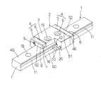
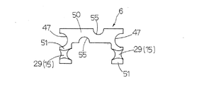
以下,図面を参照して,この発明による直動転がり案内ユニットの実施例を説明する。この発明による直動転がり案内ユニットは,概して,ベース等に取り付けるための上面49から下面へ貫通する取付け用孔18や長手方向の両側面60に沿って軌道溝11(第1軌道溝)がそれぞれ形成された軌道レール1,及び軌道レール1の長手方向に転動体を介して相対的に摺動自在なスライダ2を有している。この直動転がり案内ユニットは,転動体がボール10であって,軌道レール1とスライダ2とに形成された軌道溝11,12は二条列に形成されている。スライダ1は,主として,軌道レール1の軌道溝11に対向して形成された軌道溝12(第2軌道溝)と軌道溝11と軌道溝12との間に形成される一対の軌道路17に沿って延びる一対のリターン路20が形成されると共に各種の機器,ワーク,取付体等の物体を取り付けるための取付け用ねじ孔19が形成されたケーシング3,ケーシング3の両端面46にそれぞれ取り付けられ且つ軌道路17とリターン路20とを円弧形状に延びて連通する方向転換路15が形成されたエンドキャップ4,並びに軌道路17,リターン路20及び一対の方向転換路15で構成される循環路45を転走する複数のボール10でなる転動体を有している。エンドキャップ4は,ケーシング3側に方向転換路外周部28が形成され且つ反ケーシング側即ち摺動方向端面48側に凹部16が形成されたエンドキャップ本体5,及び反ケーシング3側に方向転換路内周部29が形成され且つエンドキャップ本体5のケーシング側に形成された凹部37に嵌合配置されたスペーサ6から構成されている。エンドキャップ4は,エンドキャップ本体5とスペーサ6とが凹凸嵌合して組み立てられている。スペーサ6は,方向転換路15の内周部29の壁面を形成する袖部51と,袖部51を繋げる本体部50とで構成されている。エンドキャップ本体5には凸部38が2つあり,スペーサ6にはエンドキャップ本体5の凸部38が嵌合する凹部55が形成されている。エンドキャップ本体5の凸部38は,断面が半円に形成されている。エンドキャップ4の軌道レール1の上面49と側面60に対向している部分は,エンドキャップ4の凹部16に組み込んだ多孔質成形体7が露出状態になっている。スペーサ6は,エンドキャップ本体5側の面に4つの凸部39が形成されている。方向転換路15は,その外周部28と内周部29とが対向して整合することによって形成されている。
Embodiments of a linear motion rolling guide unit according to the present invention will be described below with reference to the drawings. In the linear motion rolling guide unit according to the present invention, the track grooves 11 (first track grooves) are generally provided along the mounting
この直動転がり案内ユニットでは,ケーシング3は,軌道レール1の上面49側に位置する本体部13,及び本体部13の両側から軌道レール1に沿ってそれぞれ垂下して軌道レール1に跨架する一対の袖部14から構成されている。ケーシング3の袖部14には,長手方向に沿った軌道溝12と貫通孔であるリターン路20とがそれぞれ形成されている。また,エンドキャップ本体5は,ケーシング3の本体部13に対向する本体部35,及びケーシング3の袖部14に対向する袖部36から構成されている。エンドキャップ本体5の両袖部36には,ボール10の循環路45を構成する方向転換路15の外周部28の壁面が形成されている。方向転換路15は,軌道路17とリターン路20を繋ぐ円弧形状の通路で形成されている。方向転換路15のボール転走方向に直角な平面における断面形状は,ボール10の直径寸法よりも大きな直径寸法であって実質的に円形に形成されている。また,スペーサ6は,エンドキャップ本体5の本体部35に対向配置される本体部50,及びエンドキャップ本体5の袖部36に対向配置される袖部51から構成されている。スペーサ6は,方向転換路15の内周側の壁面即ち内周部29が形成されている。エンドキャップ本体5に形成された凹部16内には,潤滑剤を含浸した多孔質成形体7が嵌合されている。エンドキャップ本体5の反ケーシング側端面52には,取付け用孔21が形成された板状の端面押え板8が配置されている。スライダ端部の端面押え板8をねじで締め込むことで,多孔質成形体7は,端面押え板8に押されてエンドキャップ本体5の凹部16に押し付けられるように固定される。スライダ2は,固定ねじ9が端面押え板8に形成された取付け用孔21,エンドキャップ本体5に形成された取付け用孔22,及びスペーサ6に形成された取付け用凹溝47に挿通されてケーシング3に形成された取付け用ねじ孔23に螺入して,ケーシング3にスペーサ6,エンドキャップ本体5及び端面押え板8が固定されることによって組み立てられる。
In this linear motion rolling guide unit, the
この直動転がり案内ユニットは,主として,ボールの直径が1. 0mm以下であり,軌道レール1の幅寸法が5mm以下に構成しており,実施例では,軌道レール1のレール幅が3mmであってボール10の直径の4倍未満に形成されており,軌道レール1のレール高さが2. 6mmに形成され,また,軌道レール1が幅広構造の場合は,軌道レール1の幅寸法が6mm以下であり,軌道レール1の高さが2. 8mm以下であるミニチュアサイズであって,スライダ2に潤滑剤供給のための油孔やグリースニップルが設けられていない構造で潤滑メンテナンスフリーを実現する構成を有している。また,このミニチュアサイズの直動転がり案内ユニットでは,ケーシング3の袖部14の幅はボール直径の3倍未満であり,ケーシング3の袖部14の高さはボール直径の2. 2倍未満に形成されている。
This linear motion rolling guide unit mainly has a ball diameter of 1.0 mm or less and a width dimension of the
また,この直動転がり案内ユニットは,従来構造のスリーブタイプの多孔質成形体とは異なり,エンドキャップ本体5の端面押え板8側の凹部16に組み込まれる潤滑剤を含浸させた多孔質成形体7の体積を大きくするために,スライダ摺動方向に多孔質成形体7の寸法を延長することが可能な構造であり,多孔質成形体7に保持される潤滑剤の含浸量を増加させることができ,その結果,ボール10に対する長期間の潤滑メンテナンスフリーを実現させることができる。多孔質成形体7は,スライダ摺動方向にがたついたり浮き上がったりして動かないように,端面押え板8を固定ねじ9でケーシング3に締め込むことで,押えられて固定される。多孔質成形体7は,超高分子量の合成樹脂微粒子を押し固めて加熱成形している。多孔質成形体7の多孔部は,合成樹脂微粒子間が連通状態即ちオープンポア状態に保形された多孔部が形成されており,多孔部に潤滑剤が含浸されている。多孔質成形体7を構成する合成樹脂微粒子は,ポリエチレン又はポリプロピレンから構成されている。多孔質成形体7は,特に,図17〜図19に示すように,エンドキャップ本体5の凹部16及びエンドキャップ本体5の本体部35の下面側に位置する潤滑剤を含浸した貯留部31,貯留部31と一体構造で且つエンドキャップ本体5の袖部36の凹部16に嵌入した連係部32,及び連係部32と一体構造で且つエンドキャップ本体5の袖部36の長孔26に嵌入配置された導出部30から構成されている。貯留部31は,多量の潤滑剤を貯留可能なブロック構造であり,連係部32は,貯留部31に連係して平板状に形成され,導出部30は,連係部32から突出して方向転換路15内に潤滑剤を導出する機能を有している。導出部30は,エンドキャップ本体5の凹部16の貫通部である長孔26に嵌合して配置されている。導出部30の断面形状,言い換えれば,長孔26の断面形状は,例えば,スライダ幅方向の長さ1. 3mm(ボール直径の約160%に相当),幅が0. 45mm(ボール直径の約60%に相当)であり,両端は半径0. 225mmの円形の形状に形成されている。また,多孔質成形体7の露出面33は,導出部30の断面形状と同じに形成されている。また,エンドキャップ本体5の端面押え板8側の凹部16は,貯留部31が入る部分と連係部32が入る部分で深さが異なって形成されている。エンドキャップ本体5の貫通孔である長孔26には,多孔質成形体7の導出部30が嵌入して組み込まれている。この直動転がり案内ユニットでは,多孔質成形体7の貯留部31は,例えば,幅寸法4mm,高さ寸法0. 72mm,及び厚さが1. 17mmに形成されている。
Further, this linear motion rolling guide unit is different from a sleeve-type porous molded body having a conventional structure, and is a porous molded body impregnated with a lubricant incorporated in the
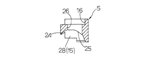
この直動転がり案内ユニットは,特に,エンドキャップ本体5に形成された方向転換路15の外周側の壁面即ち方向転換路外周部28には,ボール転走方向に細長い形状で且つ両端がR形状の長孔26の開口部25が凹部16に開口して形成されており,多孔質成形体7の導出部30が開口部25から方向転換路15に露出して配置され,ボール10自体の遠心力で長孔26の縁部53に案内されて方向転換路15を転走してボール10が多孔質成形体7の導出部30の端面42の露出面33に接して多孔質成形体7に含浸された潤滑剤がボール10に給油されることを特徴としている。即ち,長孔26は,R形状の両端部54と両端部54を連係する平行に延びる一対の縁部53から形成され,対向する縁部53間の長さは,ボール10の直径より小さく形成されている。長孔26は,エンドキャップ本体5の端面押え板8側の凹部16から方向転換路15まで貫通する貫通孔である。また,方向転換路15への導出部30の端面42である露出面33は,長孔26の縁部53の開口部25よりも凹んだ位置に設定されている。言い換えれば,長孔26の縁部53は,方向転換路15の外周部28の壁面に位置しているので,多孔質成形体7の露出面33が方向転換路15の外周部28の壁面より凹んだ位置に設定されている。露出面33は,図11に示すように,エンドキャップ本体5の長孔26に対応して,楕円や長円の形状や,細長い矩形形状を形成されている。ボール10の球面の一部が長孔26の縁部53間で露出面33側に突出して方向転換路15の外周部28を走行するので,その時にボール10が露出面33と接触することになり,その領域は,図11に示すように,長孔26の長手方向中央部に位置する接触部40となる。ボール10が露出面33に接触する接触部40は,平面状で見てスライダ幅方向において,後述のように傾斜面や平行面を成し,又は,曲面状で円筒形状の内側面やドーナツ形状の内側曲面に形成することができる。多孔質成形体7の露出面33の接触部40以外は,ボール10が方向転換路15内を転走する動きを妨げないような任意の形状として,露出面33よりもスライダ摺動方向である端面押え板8側に凹んだ形状にエンドキャップ本体5に設定されており,凸形,矩形形状の両辺が傾斜した略台形,台形の両端の頂点が曲面の形状,台形の斜面が曲面で凸形状または凹形状であってもよいものである。また,多孔質成形体7が方向転換路15に露出して配置された長孔26の両端部54の付近に,導出部30の端面42である露出面33と長孔26の壁面41とによって,潤滑剤の油溜まり部27となる凹部43が形成されている。更に,ボール10は,長孔26の両縁部53間で且つ長孔26の両端部54間の中央部分だけで,多孔質成形体7の導出部30の露出面33の少なくとも1点に接して転走するように構成されている。また,多孔質成形体7の導出部30の方向転換路15に露出する露出面33は,ボール10の転走方向に対して直角方向又は傾斜方向に延びており,多孔質成形体7の導出部30の露出面33は,軌道溝12側よりもリターン路20側の方が開口部25内でケーシング端面46側に延び出すように傾斜している。
This linear motion rolling guide unit has a wall shape on the outer peripheral side of the
また,この直動転がり案内ユニットは,多孔質成形体7の貯留部31と連係部32との端面押え板8側である正面及び/又はエンドキャップ本体5側である背面には,スライダ摺動方向に突出する複数の凸部39が形成されている。凸部39は,例えば,半球形状(半径寸法0. 08mm)の半球体に形成され,貯留部31と連係部32にそれぞれ2箇所設けられ,エンドキャップ本体5の凹部16の壁面に当接するように構成されている。貯留部31の凸部39は,例えば,貯留部31の中心から1. 72mmの位置に左右対象に配置している。凸部39は,多孔質成形体7がエンドキャップ本体5の凹部16に嵌合してケーシング3に固定されることによって,固定ねじ9の締め付け力によって凹部16の壁面に押し付けられて変形して,多孔質成形体7の摺動方向の浮き上がりやがたつきを防止でき,ボール10の多孔質成形体7の露出面33への的確な接触を確保できる。多孔質成形体7に形成された凸部39は,具体的には,貯留部31の連係部32寄りの位置と,連係部32の方向転換路15の内周部29の壁面の上側に左右対称の位置に形成されている。多孔質成形体7は,エンドキャップ本体5の凹部16内に係合固定される。多孔質成形体7のエンドキャップ4への固定方法は,スライダ2の端部に設ける端面押え板8を固定ねじ9で締め込んで,多孔質成形体7をエンドキャップ4に押し付けることで達成されるものであり,多孔質成形体7は,端面押え板8の平面部分でエンドキャップ本体5の凹部16内に押し付けられる。このとき,多孔質成形体7の凸部39が変形して,多孔質成形体7の摺動方向のガタつきや浮き上がりを防ぐことができるようになり,多孔質成形体7の全体的な異常変形が防止され,潤滑剤の供給がスムーズに行われる。
Further, this linear motion rolling guide unit is provided with a slider slide on the front surface on the end
更に,エンドキャップ本体5の凹部16に配置された多孔質成形体7は,軌道レール1の上面49と対向する部分で軌道レール1に対して露出して配置される。エンドキャップ本体5の方向転換路15の外周側壁面即ち外周部28には,貫通孔の方向転換路15側の出口部分である開口部25が設けられている。方向転換路15側の開口部25では,多孔質成形体7の導出部30の端面42が露出する露出面33が位置することになる。また,ボール10は,方向転換路15内を開口部25の長孔26の縁部53に案内されて転走し,長孔26の中央領域で,多孔質成形体7の導出部30の端面42である少なくとも露出面33に接触するように構成されている。ボール10が露出面33に接触しながら転走することによって,多孔質成形体7の導出部30に含浸されている潤滑剤が露出面33からボール10に供給されることになる。この時に,多孔質成形体7の貯留部31の潤滑剤は,ポンプ作用で連係部32,次いで導出部30を通じて露出面33まで導出される。露出面33は,エンドキャップ本体5の貫通孔の開口部25から方向転換路15側に向かって露出している。露出面33は,スライダ2の端部側である方向転換路15の外周側壁面である外周部28に設けた開口部25のボール10を案内する縁部53の位置より引っ込んだ位置に設定されている。
Further, the porous molded
この直動転がり案内ユニットでは,ボール10は,方向転換路15を転走するときに,特に,図10に示すように,接触位置を変える動きになっている。ボール10は,方向転換路15の外周部28に設けられた開口部25の手前位置までは,それ自体の遠心力を受けて外周部28の壁面に1点で接触しながら(又は非接触状態)転走する時に,ボール10と外周部28の壁面との接触位置の軌跡は1本の線状になる。開口部25のボール転走方向となる両端位置では,ボール10は開口部25の両縁部53に案内されて2点で接触して案内される。即ち,ボール10は,方向転換路15内を転走して開口部25に達すると,開口部25の縁部53と2点で接触して案内される。ボール10と外周部28の壁面との接触位置の軌跡は,開口部25の縁部形状と一致する形状になっている。次いで,開口部25の中央領域で多孔質成形体7の露出面33に接触する状態に移行し,開口部25の長孔26の中心領域では,ボール10は多孔質成形体7の露出面33に接触して転走して接触位置の軌跡は1本の線上になる。その後,ボール10は転走しながら再び開口部25の縁部53に2点で接触して,多孔質成形体7の露出面33から離れることになる。ボール10の露出面33との接触位置の変化により,ボール10は方向転換路15内を転走するときに開口部25と多孔質成形体7との境界位置に段差が存在することになるが,ボール10はエンドキャップ本体5に形成された長孔26の両縁部53に案内されてスムーズに転走するので,ボール10の転走を阻害することは無い。
In this linear motion rolling guide unit, when the
また,多孔質成形体7は,方向転換路15の外周部28の壁面の長孔26の縁部53に対して凹んだ状態で露出しており,ボール10は,軌道路17やリターン路20を転走して,略円弧形状の方向転換路15内で進行方向を変え,また,ボール10は遠心力や他のボールによる外力によって方向転換路の外周部28の壁面に沿って転走して,方向転換路15の外周部28の壁面に設けた開口部25の少なくとも一側の縁部53に案内され,多孔質成形体7の露出面33の接触部40に接触する位置へと転走し,ボール10に潤滑剤が給油される。露出面33とボール10の接触する接触部40の形状は,図11に示すように,細長い楕円形状になる。例えば,接触部40の楕円の大きさは,ボール10の転走方向の長軸長さが約0. 24mm〜0. 95mm(ボール直径の約30%から約120%に相当),短軸長さが0. 01mm〜0. 19mm(ボール直径の約1%から約20%に相当),方向転換路15内でのボール転走の角度範囲では,約11. 8°〜47. 4°に相当する。
Further, the porous molded
また,この直動転がり案内ユニットでは,特に,図6に示すように,方向転換路15の開口部25の中心位置は,実質的に円弧でなる方向転換路15に対してリターン路20側に寄った位置に設けられている。方向転換路15の中心位置に対する開口部25の中心位置のリターン路20側へのずれ量は,スライダの摺動方向に対して直角をなすスライダ幅方向において0. 35mm程度であり,この構造で,ボール10のすくい部24は,その周辺が肉厚になって強度が確保されている。また,方向転換路15に進入するボール10を,方向転換路15の外周部28の壁面で案内しながら多孔質成形体7の露出面33に衝突するときの衝撃を緩和できるように構成されている。
Further, in this linear motion rolling guide unit, as shown in FIG. 6 in particular, the center position of the
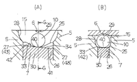
この直動転がり案内ユニットでは,多孔質成形体7の導出部30の形状については,例えば,図23〜図27に示す具体的例に形成することができる。図23〜図27では,(A)は,スライダ2の上面から見たエンドキャップ4内の方向転換路15の位置での断面図であり,(B)は方向転換路15の中心位置を通る位置の断面図がそれぞれ示されている。また,方向転換路15の外周部28の壁面の開口部25の長孔26に対して凹んだ位置に多孔質成形体7の露出面33がそれぞれ位置設定されている。また,スライダ摺動方向に対して直角を成すスライダ幅方向において,方向転換路15の中央位置と,方向転換路15の外周部28の壁面に設けた長孔26の中央位置が一致している構造である。この直動転がり案内ユニットでは,導出部30の端面42である露出面33は平面で構成され,1つ又は複数の平面,或いは,露出面33は曲面で形成されている。露出面33は,例えば,図6に示すように,スライダ2の摺動方向に対して傾斜して設けられている。露出面33の傾斜角度は,例えば,スライダ2の摺動方向に対して直角をなすケーシング端面46に対して,露出面33のリターン路20側がケーシング端面46に突き出すように,約16°傾いて形成されたり,又は,露出面33はスライダ2の摺動方向に対して直角に設けられている。
In this linear motion rolling guide unit, the shape of the lead-out
図23の(A)は,多孔質成形体7の露出面33がスライダ幅方向に対して傾斜する傾斜面34に形成されている断面図である。図23の(B)は,図23の(A)のG−G断面であって方向転換路15の中心位置を通る断面であり,多孔質成形体7の露出面33の接触部40の形状を示す断面図である。
FIG. 23A is a cross-sectional view in which the exposed
図24の(A)は,多孔質成形体7の露出面33の形状がスライダ幅方向に対して平行な平面56に形成されている断面図である。図24の(B)は,図24の(A)のH−H断面であって方向転換路15の中心位置を通る位置の断面であり,多孔質成形体7の露出面33の接触部40の形状を示す断面図である。
FIG. 24A is a cross-sectional view in which the shape of the exposed
図25の(A)は,多孔質成形体7の露出面33の形状がスライダ幅方向に対して平面の凸面57に形成されている断面図である。図25の(B)は,図25の(A)のI−I断面であって方向転換路15の中心位置を通る位置の断面であり,多孔質成形体7の露出面33の接触部40の形状を示す断面図である。言い換えれば,図25の(A)と(B)の実施形態では,多孔質成形体7の露出面33がボール10と接触する接触部40の部分が突出した凸面状態になっている。
FIG. 25A is a cross-sectional view in which the shape of the exposed
図26の(A)は,多孔質成形体7の露出面33の形状がスライダ幅方向に曲面の円弧面58に形成されている断面図である。図26の(B)は,図26の(A)のJ−J断面であって方向転換路15の中心位置を通る位置の断面であり,多孔質成形体7の露出面33の接触部40の平らな形状を示す断面図である。多孔質成形体7の露出面33の形状は,方向転換路15の最も外周側位置の壁面形状の半径寸法よりも大きい半径寸法になっている。
FIG. 26A is a cross-sectional view in which the shape of the exposed
図27の(A)は,多孔質成形体7の露出面33の形状がスライダ幅方向にドーナツ形状の環状曲面59に形成されている断面図である。図27の(B)は,図27の(A)のK−K断面であって方向転換路15の中心位置を通る位置の断面であり,多孔質成形体7の露出面33の接触部40の円弧状の形状を示す断面図である。多孔質成形体7の露出面33の形状は,方向転換路15の最も外周側位置の壁面形状の半径寸法よりも大きい半径寸法になっている。上記の各実施形態に加えて,多孔質成形体の露出面が開口部よりも凹んだ状態の1つまたは複数の平面,或いは,1つ又は複数の曲面から形成されたものがある。また,開口部から露出して,方向転換路の壁面形状の曲率に一致した曲面,或いは僅かに方向転換路側に突出した形状に形成されたタイプにも形成できる。
FIG. 27A is a cross-sectional view in which the shape of the exposed
この発明による直動転がり案内ユニットは,半導体製造装置,精密機械,測定・検査装置,医療機器,各種ロボット,各種組立装置,搬送機械,工作機械,マイクロマシーン等の各種装置における摺動部に組み込んで利用して好ましいものである。 The linear motion rolling guide unit according to the present invention is incorporated in sliding parts of various devices such as semiconductor manufacturing equipment, precision machinery, measurement / inspection equipment, medical equipment, various robots, various assembling equipment, transfer machines, machine tools, micromachines, etc. It is preferable to use it.
1 軌道レール
2 スライダ
3 ケーシング
4 エンドキャップ
5 エンドキャップ本体
6 スペーサ
7 多孔質成形体
10 ボール(転動体)
11 軌道溝(第1軌道溝)
12 軌道溝(第2軌道溝)
15 方向転換路
16 凹部
17 軌道路
20 リターン路
25 開口部
26 長孔
27 油溜まり部
28 方向転換路外周部
29 方向転換路内周部
30 導出部
33 露出面
34 傾斜面
39 凸部
40 接触部
41 壁面
42,46,48 端面
43 凹部
45 循環路
49 上面
53 長孔の縁部
54 長孔の端部
60 側面
DESCRIPTION OF
11 Track groove (first track groove)
12 Track groove (second track groove)
DESCRIPTION OF
Claims (3)
前記方向転換路の外周部の壁面には,前記エンドキャップの前記凹部から延びて前記ボールの転走方向に細長い形状の長孔が開口して形成されて成り,前記長孔は,R形状の両端部と前記両端部をそれぞれ結ぶ互いに平行に延びる一対の縁部に形成され,対向する前記縁部間の長さが前記ボールの直径より小さく形成されており,
前記多孔質成形体の導出部が前記長孔に露出した露出面に構成され,前記露出面は,前記方向転換路の前記外周部の前記壁面に位置する前記長孔の前記両縁部よりも凹んだ位置に設定されており,
前記方向転換路の前記ボールが前記長孔の前記両縁部に沿って案内され転走するときに前記ボールの球面の一部が前記縁部間から前記露出面側に突出して前記ボールが前記長孔の中央部分の1点で前記多孔質成形体の前記露出面に接して前記多孔質成形体に含浸された前記潤滑剤が前記ボールに給油されることを特徴とする直動転がり案内ユニット。 A track rail having first track grooves formed along both side surfaces in the longitudinal direction; and a slider slidable in the longitudinal direction across the track rail. A casing in which a second raceway groove is formed opposite to one raceway groove and a return path extending along a pair of raceway paths formed between the second raceway groove and the first raceway groove is formed. , End caps that are respectively attached to both end faces of the casing and that form a direction change path that communicates the track path and the return path in an arc, and the track path, the return path, and the pair of the direction changes. A porous body having a ball made of a plurality of rolling elements that roll on a circulation path constituted by a path, and having a recess impregnated with a lubricant in a recess formed on the end surface side in the sliding direction of the end cap In the linear motion rolling guide unit consists of features is fitted,
Wherein the wall surface of the outer peripheral portion of the direction changing passage, become elongated shape of the slot in the rolling direction of the ball extending from said recess of said end cap is formed with an opening, the elongated hole is, R shape Are formed at a pair of edges extending in parallel with each other, and the length between the opposing edges is smaller than the diameter of the ball,
The lead-out portion of the porous molded body is configured as an exposed surface exposed in the long hole, and the exposed surface is more than the both edge portions of the long hole located on the wall surface of the outer peripheral portion of the direction change path. Is set in a recessed position,
Wherein said ball the ball of the direction change path protrudes from between the portion of the edge of the spherical surface of the ball when rolling is guided along the edges of the slot on the exposed face A linear motion rolling guide unit characterized in that the lubricant impregnated in the porous molded body is in contact with the exposed surface of the porous molded body at one point of the central portion of the long hole and is supplied to the ball. .
Priority Applications (2)
| Application Number | Priority Date | Filing Date | Title |
|---|---|---|---|
| JP2011236761A JP5876706B2 (en) | 2011-10-28 | 2011-10-28 | Linear motion rolling guide unit |
| US13/661,658 US8858080B2 (en) | 2011-10-28 | 2012-10-26 | Linear motion guide unit using balls |
Applications Claiming Priority (1)
| Application Number | Priority Date | Filing Date | Title |
|---|---|---|---|
| JP2011236761A JP5876706B2 (en) | 2011-10-28 | 2011-10-28 | Linear motion rolling guide unit |
Publications (3)
| Publication Number | Publication Date |
|---|---|
| JP2013096431A JP2013096431A (en) | 2013-05-20 |
| JP2013096431A5 JP2013096431A5 (en) | 2014-11-27 |
| JP5876706B2 true JP5876706B2 (en) | 2016-03-02 |
Family
ID=48172530
Family Applications (1)
| Application Number | Title | Priority Date | Filing Date |
|---|---|---|---|
| JP2011236761A Active JP5876706B2 (en) | 2011-10-28 | 2011-10-28 | Linear motion rolling guide unit |
Country Status (2)
| Country | Link |
|---|---|
| US (1) | US8858080B2 (en) |
| JP (1) | JP5876706B2 (en) |
Families Citing this family (9)
| Publication number | Priority date | Publication date | Assignee | Title |
|---|---|---|---|---|
| JP6390616B2 (en) * | 2013-07-04 | 2018-09-19 | 日本精工株式会社 | Oil supply device for linear guide device, linear guide device |
| JP2015055374A (en) * | 2013-09-10 | 2015-03-23 | 住友重機械工業株式会社 | Ultra-low temperature freezer |
| JP6234758B2 (en) * | 2013-09-25 | 2017-11-22 | 日本トムソン株式会社 | Linear motion guide unit with lubrication member |
| JP2015090187A (en) | 2013-11-06 | 2015-05-11 | 日本精工株式会社 | Rolling bearing guide device |
| JP6403992B2 (en) * | 2014-05-28 | 2018-10-10 | 日本トムソン株式会社 | Linear motion rolling guide unit |
| JP6407566B2 (en) * | 2014-05-28 | 2018-10-17 | 日本トムソン株式会社 | Linear motion rolling guide unit |
| JP6445788B2 (en) | 2014-05-30 | 2018-12-26 | 日本トムソン株式会社 | Linear motion rolling guide unit |
| EP3225862B1 (en) * | 2016-03-29 | 2018-08-22 | Hiwin Technologies Corp. | Linear slide having lubricating device |
| CN110195743A (en) * | 2019-05-22 | 2019-09-03 | 浙江非攻机械有限公司 | Roller linear guide rail device |
Family Cites Families (13)
| Publication number | Priority date | Publication date | Assignee | Title |
|---|---|---|---|---|
| JPS61133122U (en) * | 1985-02-08 | 1986-08-20 | ||
| JPH0571443U (en) * | 1992-03-02 | 1993-09-28 | 光洋精工株式会社 | Direct acting guide device |
| JPH07110030A (en) * | 1993-10-12 | 1995-04-25 | Nippon Seiko Kk | Rectilinearly moving device having lubricant supply member |
| JP3733654B2 (en) * | 1996-08-30 | 2006-01-11 | 日本精工株式会社 | Lubricating linear guide device with lubricant-containing polymer |
| JP4070265B2 (en) * | 1997-07-01 | 2008-04-02 | Thk株式会社 | Linear guide device |
| JP3980778B2 (en) * | 1998-11-06 | 2007-09-26 | 日本トムソン株式会社 | Linear motion guidance unit |
| JP4502290B2 (en) | 1999-09-10 | 2010-07-14 | 日本トムソン株式会社 | Linear motion rolling guide unit |
| JP4274744B2 (en) * | 2002-05-31 | 2009-06-10 | Thk株式会社 | Lubricating oil supply device and linear guide device using the same |
| JP4152362B2 (en) | 2004-07-30 | 2008-09-17 | 日本トムソン株式会社 | Rolling guide unit |
| JP4685723B2 (en) * | 2005-09-06 | 2011-05-18 | 日本トムソン株式会社 | Linear motion guidance unit |
| JP4584888B2 (en) * | 2006-09-27 | 2010-11-24 | 日本トムソン株式会社 | Linear motion guidance unit |
| JP4986775B2 (en) * | 2007-09-05 | 2012-07-25 | 日本トムソン株式会社 | Slider for linear motion rolling guide unit |
| JP5052270B2 (en) * | 2007-09-13 | 2012-10-17 | 日本トムソン株式会社 | Slider for linear motion rolling guide unit |
-
2011
- 2011-10-28 JP JP2011236761A patent/JP5876706B2/en active Active
-
2012
- 2012-10-26 US US13/661,658 patent/US8858080B2/en active Active
Also Published As
| Publication number | Publication date |
|---|---|
| US20130108194A1 (en) | 2013-05-02 |
| JP2013096431A (en) | 2013-05-20 |
| US8858080B2 (en) | 2014-10-14 |
Similar Documents
| Publication | Publication Date | Title |
|---|---|---|
| JP5876706B2 (en) | Linear motion rolling guide unit | |
| US6813968B2 (en) | Ball screw device and linear motion device | |
| JP4505397B2 (en) | Linear motion guidance unit | |
| JP4584888B2 (en) | Linear motion guidance unit | |
| US7780356B2 (en) | Slider for linear motion rolling guide unit | |
| JP7194794B2 (en) | Linear guide unit | |
| US7927016B2 (en) | Slider for linear motion rolling guide unit | |
| JP6403992B2 (en) | Linear motion rolling guide unit | |
| JP2011149469A (en) | Linear motion guide unit | |
| US7121723B2 (en) | Linear guide apparatus | |
| JP4469705B2 (en) | Linear motion guidance unit | |
| JP6393496B2 (en) | Linear motion guide unit with lubrication member | |
| JP5938196B2 (en) | Linear motion rolling guide unit | |
| JP6945980B2 (en) | How to load the rolling element into the bending rolling guide unit and its slider | |
| CN110307255B (en) | Roller retainer type bearing | |
| JP6777416B2 (en) | Ball screw | |
| JP2018135981A (en) | Linear motion guide unit | |
| JP6407566B2 (en) | Linear motion rolling guide unit | |
| JP4634223B2 (en) | Linear motion guidance unit | |
| CN110307259B (en) | Roller retainer type bearing | |
| JP2014234858A5 (en) | ||
| JP7114976B2 (en) | cage and roller | |
| JP4280376B2 (en) | Linear motion rolling guide unit | |
| JP2001132745A (en) | Linearly moving rolling guide unit | |
| JP2017180664A (en) | Ball Screw |
Legal Events
| Date | Code | Title | Description |
|---|---|---|---|
| A521 | Request for written amendment filed |
Free format text: JAPANESE INTERMEDIATE CODE: A523 Effective date: 20141010 |
|
| A621 | Written request for application examination |
Free format text: JAPANESE INTERMEDIATE CODE: A621 Effective date: 20141010 |
|
| A977 | Report on retrieval |
Free format text: JAPANESE INTERMEDIATE CODE: A971007 Effective date: 20150403 |
|
| A131 | Notification of reasons for refusal |
Free format text: JAPANESE INTERMEDIATE CODE: A131 Effective date: 20150616 |
|
| A521 | Request for written amendment filed |
Free format text: JAPANESE INTERMEDIATE CODE: A523 Effective date: 20150717 |
|
| TRDD | Decision of grant or rejection written | ||
| A01 | Written decision to grant a patent or to grant a registration (utility model) |
Free format text: JAPANESE INTERMEDIATE CODE: A01 Effective date: 20160119 |
|
| A61 | First payment of annual fees (during grant procedure) |
Free format text: JAPANESE INTERMEDIATE CODE: A61 Effective date: 20160122 |
|
| R150 | Certificate of patent or registration of utility model |
Ref document number: 5876706 Country of ref document: JP Free format text: JAPANESE INTERMEDIATE CODE: R150 |
|
| R250 | Receipt of annual fees |
Free format text: JAPANESE INTERMEDIATE CODE: R250 |
|
| R250 | Receipt of annual fees |
Free format text: JAPANESE INTERMEDIATE CODE: R250 |