JP5876035B2 - Bottle accessories for attaching a drinking mouth that can be retracted using a cap to a bottle - Google Patents
Bottle accessories for attaching a drinking mouth that can be retracted using a cap to a bottle Download PDFInfo
- Publication number
- JP5876035B2 JP5876035B2 JP2013506811A JP2013506811A JP5876035B2 JP 5876035 B2 JP5876035 B2 JP 5876035B2 JP 2013506811 A JP2013506811 A JP 2013506811A JP 2013506811 A JP2013506811 A JP 2013506811A JP 5876035 B2 JP5876035 B2 JP 5876035B2
- Authority
- JP
- Japan
- Prior art keywords
- bottle
- housing
- cap
- spout
- neck
- Prior art date
- Legal status (The legal status is an assumption and is not a legal conclusion. Google has not performed a legal analysis and makes no representation as to the accuracy of the status listed.)
- Expired - Fee Related
Links
Images


Classifications
-
- B—PERFORMING OPERATIONS; TRANSPORTING
- B65—CONVEYING; PACKING; STORING; HANDLING THIN OR FILAMENTARY MATERIAL
- B65D—CONTAINERS FOR STORAGE OR TRANSPORT OF ARTICLES OR MATERIALS, e.g. BAGS, BARRELS, BOTTLES, BOXES, CANS, CARTONS, CRATES, DRUMS, JARS, TANKS, HOPPERS, FORWARDING CONTAINERS; ACCESSORIES, CLOSURES, OR FITTINGS THEREFOR; PACKAGING ELEMENTS; PACKAGES
- B65D47/00—Closures with filling and discharging, or with discharging, devices
- B65D47/04—Closures with discharging devices other than pumps
- B65D47/06—Closures with discharging devices other than pumps with pouring spouts or tubes; with discharge nozzles or passages
- B65D47/061—Closures with discharging devices other than pumps with pouring spouts or tubes; with discharge nozzles or passages with telescopic, retractable or reversible spouts, tubes or nozzles
-
- B—PERFORMING OPERATIONS; TRANSPORTING
- B65—CONVEYING; PACKING; STORING; HANDLING THIN OR FILAMENTARY MATERIAL
- B65D—CONTAINERS FOR STORAGE OR TRANSPORT OF ARTICLES OR MATERIALS, e.g. BAGS, BARRELS, BOTTLES, BOXES, CANS, CARTONS, CRATES, DRUMS, JARS, TANKS, HOPPERS, FORWARDING CONTAINERS; ACCESSORIES, CLOSURES, OR FITTINGS THEREFOR; PACKAGING ELEMENTS; PACKAGES
- B65D51/00—Closures not otherwise provided for
- B65D51/18—Arrangements of closures with protective outer cap-like covers or of two or more co-operating closures
Description
本発明は、従来の蓋締機を用いることによってキャップによりボトルに付与するためのボトル付属品であって、ボトル内に保持されたボトル付属品によりキャップがボトルから後で取り外されることを可能にするボトル付属品に関する。本発明は、引っ込められる飲み口装置をボトルに付与するために特に有用であり、従ってかかる付与に対して以下に記載される。 The present invention is a bottle accessory for applying to a bottle with a cap by using a conventional lid clamping machine, and allows the cap to be later removed from the bottle by a bottle accessory held in the bottle. Related to bottle accessories. The present invention is particularly useful for applying a retractable spout device to a bottle and is therefore described below for such application.
本発明は、本出願人の先行する米国特許第6026994号及び第6976610号に開示された引っ込められる飲み口装置で特に有用であり、それらの内容は参考としてここに組み込まれる。 The present invention is particularly useful with the retractable spout device disclosed in Applicants' prior US Pat. Nos. 6,026,994 and 6,976,610, the contents of which are hereby incorporated by reference.
本出願人の先行する米国特許第6026994号は、キャップにより閉じられるボトルの首に付与するための引っ込められる飲み口装置を記載する。この装置は、ボトルの首内に固定して受け入れ可能な套管状ハウジング、及びこのハウジングがボトル首内に固定されかつボトル首がキャップにより閉じられるとき、ハウジング内で引っ込められた位置からボトルの内容物を注ぐためにハウジング及びボトル首から外向きに突出する延びた位置まで可動な飲み口を含む。キャップを除去することで飲み口を自動的に延ばさせるために、この装置はさらに、飲み口をその延びた位置に偏位させるばねを含む。かかるばねは省略されることができ、それにより飲み口はキャップの除去と一緒にまたは除去後にその延びた位置に手で動かされることができるであろう。ボトルの液体内容物が飲み口を通して注ぎ出されるときに空気をボトル中に戻すために空気戻り通路が設けられる。 Applicant's prior US Pat. No. 6,026,994 describes a retractable spout device for application to the neck of a bottle closed by a cap. The device includes a tubular housing fixedly received within a bottle neck, and the contents of the bottle from a retracted position within the housing when the housing is secured within the bottle neck and the bottle neck is closed by a cap. It includes a drinking spout which is movable to an extended position protruding outwardly from the housing and bottle neck for pouring objects. In order to automatically extend the spout by removing the cap, the device further includes a spring that biases the spout into its extended position. Such a spring can be omitted, so that the spout can be moved manually into its extended position with or after removal of the cap. An air return passage is provided to return air into the bottle as the liquid content of the bottle is poured out through the spout.
本出願人の先行する米国特許第6976610号は、装置を構造的によりコンパクトにしかつ操作をより信頼性あるものにするだけでなく、連結円盤を含むことにより、装置を存在するボトル蓋締機に順応させ、従ってそれらを引っ込められる飲み口装置を組み込んでいるキャップを付与するために使用可能にするためにかかる高価な機械に実質的に変化を要求しない引っ込められる飲み口装置の構造の改善を記載する。 Applicant's prior U.S. Pat. No. 6,976,610 not only makes the device structurally more compact and more reliable in operation, but also includes a connecting disk to make the device an existing bottle cap. Describes improvements in the structure of retractable spout devices that do not require substantial changes to such expensive machines to adapt and thus enable them to be used to apply caps that incorporate retractable spout devices To do.
本出願人の先行する米国特許第6976610号に記載された構造に存在することが見い出された欠点は、キャップ及び飲み口装置がボトルに付与された後に、連結円盤を持つキャップの除去がボトルから飲み口ハウジングを引っ張り出す傾向があるかもしれないという可能性である。 A disadvantage found to be present in the structure described in Applicant's prior US Pat. No. 6,976,610 is that the removal of the cap with the connecting disc from the bottle after the cap and spout device has been applied to the bottle. The possibility that there may be a tendency to pull out the spout housing.
本発明の目的は、キャップによりボトルの首に付与するためのボトル付属品を提供することであり、その装置は、キャップがボトル首から連結円盤と一緒に除去されるときに連結円盤からのハウジングの解放をより確実にするものである。 The object of the present invention is to provide a bottle accessory for application to the neck of a bottle by a cap, the device comprising a housing from a coupling disk when the cap is removed together with the coupling disk from the bottle neck. This will ensure the release of
本発明の広い態様によれば、キャップによりボトルの首に付与するためのボトル付属品であって、ボトル首内に固定して受け入れられる寸法をしたハウジング;及び前記ハウジングの上端に取り付けられかつキャップ内に受け入れ可能な連結円盤であって、連結円盤とハウジングがキャップによりボトルの首に付与されることを可能にするものを含むものにおいて、前記ハウジングの上端が、ハウジングの外周縁から内向きに間隔を置かれかつハウジングの軸方向に延びる環状溝を形成されていること、及び前記連結円盤が、前記キャップ内に固定して受け入れられる寸法をし、キャップのためのライナーとしての役目をする環状周囲表面を持つ下面を含むことを特徴とし、さらに連結円盤の前記下面がまた、連結円盤の周囲から内向きに間隔を置かれた環状リブを含み、前記環状リブが、ハウジングの軸方向に延び、かつ連結円盤がキャップによりボトル首へのハウジングの取り付けを容易にしかつボトル首からのキャップの除去によりハウジングから解放するように前記ハウジングの上端の前記環状溝内に解放可能に保持される寸法をしており、それによりハウジングがボトルネック内に残る間に連結円盤が除去されたキャップのためのライナーとしての役目もすることを可能にすることを特徴とするボトル付属品が提供される。 In accordance with a broad aspect of the present invention, a bottle accessory for application to a bottle neck by a cap, dimensioned to be fixedly received within the bottle neck; and a cap attached to the upper end of the housing and the cap A coupling disk receivable within, wherein the coupling disk and the housing allow the cap to be applied to the neck of the bottle by a cap, the upper end of the housing being inward from the outer periphery of the housing An annular groove spaced apart and extending in the axial direction of the housing is formed, and the annular ring is dimensioned to be fixedly received within the cap and serves as a liner for the cap Characterized in that it includes a lower surface having a peripheral surface, and further wherein the lower surface of the connecting disk is also spaced inwardly from the periphery of the connecting disk. The annular rib extends in the axial direction of the housing, and the connecting disc facilitates attachment of the housing to the bottle neck by the cap and releases from the housing by removal of the cap from the bottle neck. Is dimensioned to be releasably retained in the annular groove at the upper end of the housing, so that it also serves as a liner for the cap from which the connecting disc has been removed while the housing remains in the bottleneck A bottle accessory is provided that is characterized in that it is possible to do so.
以下に述べられる本発明の好適な実施態様によれば、ハウジングの上端の環状溝は、外部環状側壁、及び外部環状側壁から内向きに間隔を置かれた内部環状側壁を含み、外部環状側壁は、半径方向に延びる環状溝を形成された内表面を持ち、連結円盤の下面の環状リブの外表面は、環状溝に受け入れ可能な半径方向に延びる環状ビードを持つ。ハウジングの上端は、軸方向に延びる環状凹所を形成された上部部分、及びキャップを受け入れるためのねじ山を形成された下にある部分を含む。ハウジングの上部部分はさらに、ハウジングの上部と下にある部分の間に弾性接合部を含む。 According to a preferred embodiment of the invention described below, the annular groove at the upper end of the housing includes an outer annular side wall and an inner annular side wall spaced inwardly from the outer annular side wall, the outer annular side wall being The outer surface of the annular rib on the lower surface of the connecting disk has a radially extending annular bead that can be received in the annular groove. The upper end of the housing includes an upper portion formed with an axially extending annular recess and an underlying portion formed with a thread for receiving a cap. The upper portion of the housing further includes an elastic joint between the upper and lower portions of the housing.
本発明の二つの実施態様が例示目的のために以下に述べられる。一つの述べられた実施態様では、ハウジングの上部部分は、ハウジングの下にある部分の外径より小さい外径を持ち、弾性接合部の上部部分の半径方向たわみを可能にするための環状空間を規定し、それによりボトル首内へのハウジングの挿入後のボトル首からのキャップの除去によりハウジングからの連結円盤の解放を容易にする。この実施態様では、飲み口ハウジングは、飲み口ハウジングがボトル首内に挿入されるときに上部部分の外端がボトル首の外端と実質的に同一平面であるような寸法をしている。 Two embodiments of the invention are described below for illustrative purposes. In one described embodiment, the upper portion of the housing has an outer diameter that is smaller than the outer diameter of the portion under the housing, and an annular space is provided to allow radial deflection of the upper portion of the elastic joint. Defining, thereby facilitating release of the connecting disc from the housing by removal of the cap from the bottle neck after insertion of the housing into the bottle neck. In this embodiment, the spout housing is dimensioned such that the outer end of the upper portion is substantially flush with the outer end of the bottle neck when the spout housing is inserted into the bottle neck.
第二の述べられた好適な実施態様では、ハウジングの上部部分は、ハウジングの下にある部分の外径より大きい外径を持ち、ハウジングは、下にある部分から内向きに軸方向に延びる環状凹所を含み、下にある部分の内向き半径方向たわみ、それにより上部部分の外向き半径方向たわみを可能にする環状空間を弾性接合部に規定する。これは、ボトル首内へのハウジングの挿入後のボトル首からのキャップの除去によりハウジングからの連結円盤の解放を容易にする。この実施態様では、飲み口ハウジングは、飲み口ハウジングがボトル首内に挿入されるときに上部部分の外端がボトル首の外端から外向きに突出するような寸法をしている。 In the second described preferred embodiment, the upper portion of the housing has an outer diameter that is greater than the outer diameter of the underlying portion, and the housing is annularly extending axially inwardly from the underlying portion. An elastic space is defined in the elastic joint that includes a recess and allows an inward radial deflection of the underlying portion, thereby allowing an outward radial deflection of the upper portion. This facilitates release of the connecting disc from the housing by removal of the cap from the bottle neck after insertion of the housing into the bottle neck. In this embodiment, the spout housing is dimensioned such that the outer end of the upper portion projects outwardly from the outer end of the bottle neck when the spout housing is inserted into the bottle neck.
上に示されたように、本発明は、ボトル首に付与される引っ込められる飲み口装置のために特に有用であり、従ってその用途に関して以下に説明される。 As indicated above, the present invention is particularly useful for a retractable spout device applied to a bottle neck and is therefore described below with respect to its use.
従って、本発明のより特別な態様によれば、キャップによりボトルの首に付与するための引っ込められる飲み口装置であって、ボトル首内に固定して受け入れられるような寸法をした飲み口ハウジング;ハウジングがボトル首内に固定されかつキャップがボトル首の上に付与されるときの飲み口ハウジング内の引っ込んだ位置からボトルの内容物を注ぎ出すための飲み口ハウジング及びボトル首から外向きに突出する延びた位置まで前記飲み口ハウジング内で可動な飲み口;及びキャップによりボトルの首に付与されるように前記ハウジングの上端に取り付けられた連結円盤を含むものにおいて、前記飲み口ハウジングの上端が、飲み口ハウジングの外周縁から内向きに間隔を置かれかつハウジングの軸方向に延びる環状溝を形成されていること、及び前記連結円盤が、前記キャップ内に固定して受け入れられる寸法をし、キャップのためのライナーとしての役目をする環状周囲表面を持つ下面を含むことを特徴とし、さらに連結円盤の前記下面がまた、連結円盤の周囲から内向きに間隔を置かれた環状リブを含み、前記環状リブが、飲み口ハウジングから軸方向に延び、かつ連結円盤がキャップによりボトル首への飲み口ハウジングの取り付けを容易にしかつボトル首からのキャップの除去により飲み口ハウジングから解放するように前記飲み口ハウジングの上端の前記環状溝内に解放可能に保持される寸法をしており、それにより飲み口ハウジング及び飲み口がボトル首内に残る間に連結円盤が除去されたキャップのためのライナーとしての役目もすることを可能にすることを特徴とする引っ込められる飲み口装置が提供される。 Thus, according to a more particular aspect of the present invention, a retractable spout device for application to the neck of a bottle by a cap, the spout housing dimensioned to be fixedly received within the bottle neck; A spout housing for pouring out the contents of the bottle from the retracted position in the spout housing when the housing is secured in the bottle neck and the cap is applied over the bottle neck and protrudes outward from the bottle neck A drinking spout movable within the spout housing to an extended position; and a connecting disc attached to the top end of the housing to be attached to the neck of the bottle by a cap, wherein the top end of the spout housing is An annular groove is formed inwardly spaced from the outer periphery of the spout housing and extending in the axial direction of the housing And the lower surface of the connecting disk, wherein the lower surface of the connecting disk is further dimensioned to be fixedly received within the cap and having an annular peripheral surface that serves as a liner for the cap. Also includes an annular rib spaced inwardly from the periphery of the coupling disk, the annular rib extending axially from the drinking hole housing, and the coupling disk being attached to the bottle neck by the cap And is releasably retained in the annular groove in the upper end of the spout housing so as to be released from the spout housing by removal of the cap from the bottle neck, whereby the spout housing and To allow the connecting disc to serve as a liner for the removed cap while the spout remains in the bottle neck Spout device retracted and symptoms are provided.
本発明のさらなる特徴及び利点は以下の説明から明らかとなるであろう。 Further features and advantages of the present invention will become apparent from the following description.
前述の図面、及び以下の説明は、主として現在好適な実施態様であると考えられるものを含む本発明の概念的態様及びそれらの可能な実施態様を理解することを容易にする目的のために提供されることは理解されるべきである。明解さ及び簡潔さのために、当業者が通常の技能及び設計を用いて、説明された発明を理解及び実施することを可能にするために必要なものより多い詳細を提供する試みはなされていない。説明された実施態様は例示目的だけのためにあること、及び本発明はここに説明された以外の形及び用途で実施されることができることは、さらに理解されるべきである。 The foregoing drawings, and the following description, are provided for the purpose of facilitating understanding of the conceptual aspects of the present invention and their possible embodiments, including those considered to be presently preferred embodiments. It should be understood that For clarity and brevity, attempts have been made to provide more detail than is necessary to enable one of ordinary skill in the art to understand and practice the described invention using ordinary skill and design. Absent. It should be further understood that the described embodiments are for illustrative purposes only and that the invention can be practiced in other forms and applications than those described herein.
図1−3の実施態様
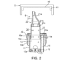
図1−3は、キャップ6(図2)により閉じられた首4を形成された2で概略的に示されたボトルに付与された本出願人の先行する米国特許第6976610号に記載されたタイプの引っ込められる飲み口装置を示す。図1及び2にBで概括的に示された飲み口装置は、ボトル2の首4内に固定して受け入れられ、従ってそれは繰り返して付与されかつ除去される必要がない。従って、キャップ6が除去されるときはいつでも、装置B内の飲み口は、ボトル内容物を注ぎ出すために使用されることを可能にする延びた位置(図2)に自動的に動き、キャップが再付与されるときはいつでも、それはその引っ込んだ位置(図1)に戻すように飲み口を自動的に動かす。
1-3. FIG. 1-3 shows the applicant's prior U.S. patent granted to a bottle, shown schematically at 2, formed with a neck 4 closed by a cap 6 (FIG. 2). Figure 6 shows a retractable spout device of the type described in US 6976610. 1 and 2 is generally received in a fixed manner within the neck 4 of the
飲み口装置Bは、ボトル首4内に固定して受け入れられる10で概括的に示されたハウジング;ハウジングを通して延びかつそこでボトルから内容物を注ぐのを容易にするためにボトル首から外向きに突出する延びた位置(図2)まで、及びキャップ6により閉じられたときにボトル首内に配置された引っ込んだ位置(図1)まで移動可動な20で概括的に示された飲み口;及び飲み口20をその延びた位置に通常促すが、ボトル首4へのキャップの付与により飲み口をその引っ込んだ位置に自動的に動かすように圧縮可能な30(図2)で概括的に示されたコイル状のばねを含む。
The spout device B is a housing generally indicated at 10 that is fixedly received within the bottle neck 4; extends through the housing and outwards from the bottle neck to facilitate pouring the contents from the bottle there. A spout shown generally at 20 movable to a protruding extended position (FIG. 2) and to a retracted position (FIG. 1) placed in the bottle neck when closed by the
ハウジング10は、飲み口装置がボトル首に付与されるときにボトル2の内部と連通する開口13を形成された挿入体12をその下端に持つ円筒状部分11を含む。
The
飲み口装置20は二つのはめ込み部分21,22を含む。外部はめ込み部分21の外端21aは、ボトルからグラスまたは他の容器中への液体の排出を容易にするために先細り断面を有する。はめ込み部分21の反対端は、その内表面上に、ばね30のための座部としての役目をする環状肩21bを形成され、はめ込み部分21の外向き移動を制限するために、はめ込み部分22の内表面内の対応する肩と係合可能な外部環状肩21cを形成されている。
The
はめ込み部分22は、はめ込み部分22の突出位置を制限するために、その反対端に、ハウジング円筒状部分11の対応する端部の内向き先細り表面11aと共働可能な外向き末広がり表面22aを形成されている。
The
ハウジング10の円筒状部分11は、二つの通路(すなわち、ボトル2から注がれる液体(または他の注ぎ可能な物質)のための第一通路14;及びその内容物が注がれるときにボトルの内部中へ空気を戻すための空気通路15)を形成されている。
The
従って、キャップ6が除去されるたびに、飲み口20は、ばね30によりその延びた位置に自動的に動かされ、空気が通路15を介してボトルの内部中に戻されながら、飲み口の通路14を介してボトルの内容物を注ぎ出すために飲み口を使用することを可能にすることがわかるであろう。キャップ6がボトル首4に再付与されるとき、飲み口20はキャップによりその引っ込んだ位置に自動的に動かされ、それはばね30の圧縮により可能にされる。従って、キャップが飲み口装置を含むボトルに再付与されるたびに、従来の飲み口構造のように飲み口装置を除去する必要がない。
Thus, each time the
図1−3に示された構造では、この装置はさらに、40で概括的に示された連結円盤を含む。円盤40は実際には二つの機能を果たす:その主機能は、引っ込められる飲み口装置をキャップ6に連結し、かつこの装置をキャップ内に保持するための連結器としての役目をし、それにより、引っ込められる飲み口装置を持つキャップを、存在するボトル充填及び蓋締機により取り扱われるのを可能にする。円盤40はまた、ボトルに取り付けられたときにキャップのためのライナーとしての役目をし、それは、図1に示されたように、キャップが引っ込んだ位置の飲み口20を持って付与されるときにボトルを封止する。
In the structure shown in FIGS. 1-3, the apparatus further includes a connecting disk, indicated generally at 40. The
本発明によれば、飲み口ハウジング10の上端、及び連結円盤40の下表面は、連結円盤40を、飲み口ハウジング10と一緒に、通常の蓋締機を用いてキャップに付与されることを可能にする態様で構成され、一方同時にキャップがボトルからはずされるときに連結円盤からの飲み口ハウジングの解放をより確実にし、従って連結円盤は、キャップのためのライナーとしての役目をするためにキャップ内に保持されるであろうし、かつ飲み口ハウジングは、キャップが除去されるときにそこからの内容物の注ぎをその後に容易にするためにボトル首内に保持されるであろう。
According to the present invention, the upper end of the
従って、特に図3の拡大された断片図に示されるように、ハウジング10の円筒11の上部は、環状外部側壁16a、内部環状側壁16b、及び底壁16cにより規定される環状溝または凹所16を一体的に形成されている。外部環状側壁16aの内表面は、半径方向に延びる溝16dを形成されている。
Thus, as particularly shown in the enlarged fragmentary view of FIG. 3, the upper portion of the
連結円盤40の内面は、環状溝16内に受け入れ可能でありかつ溝の幅より小さい厚さを持つ環状壁またはリブ42を形成されている。環状リブ42の外表面は、ハウジング円筒11の上端の外部環状壁16aの環状溝16d内に受け入れ可能である、半径方向に延びる拡大された丸いビード形成体42aを形成されている。
The inner surface of the connecting
ハウジング円筒11の上端はさらに、側壁16aの下にある部分17を形成されかつボトルキャップ(図2の6)を受けるためのねじ山17aを形成されている。ハウジングの部分17は、深い環状凹所18によりハウジング円筒部分11の上端から半径方向に間隔を置かれている。好ましくは、部分17は、そのねじ付き部17aにおいて、凹所16の底壁16cの厚さより大きい厚さを持ち、従って弾性接合部17bは、上部ハウジング部分の底壁16cと、下にある部分17との間に形成される。
The upper end of the
図1−3の実施態様では、ハウジングの環状壁16aの外表面は、以下に述べるように、ハウジングの壁16aの外向き半径方向たわみを可能にするために、それとボトル首4の間に環状空間19を規定するために外径を減少される。
In the embodiment of FIGS. 1-3, the outer surface of the housing
従って、図1−3の実施態様は次のように作用する:まず、飲み口装置20を含む飲み口ハウジング10が、連結円盤の環状リブ42をハウジングの凹所16中に単にはめ込むことにより連結円盤40に取り付けられる。かかる場合に、壁16aの環状溝16d内に受け入れられた壁42のリブ42aは、連結円盤に取り付けられた飲み口装置を固定して、しかし解放可能に保持する。従って、連結円盤40は、それに解放可能に取り付けられた飲み口装置と共に、連結円盤及び飲み口装置をキャップに蓋締めするために従来の蓋締機で使用されることができる。
Accordingly, the embodiment of FIGS. 1-3 operates as follows: First, the
キャップ、及びそれに取り付けられた飲み口装置がボトル首4中に挿入されるとき、ハウジングの上端の力強い挿入は、上端を外向きに曲げさせ、これは、ハウジングの上部部分とその下にある部分の間の弾性接合部17bにより可能にされる。外部環状壁16aのこの外向き曲がりは、空間19により可能にされ、かつ環状壁16aの上端内の環状溝16dを連結円盤40の環状リブ42内のビード42aから離れるように動かす。
When the cap and the spout device attached to it are inserted into the bottle neck 4, the strong insertion of the upper end of the housing causes the upper end to bend outward, which is the upper part of the housing and the part below it It is made possible by the elastic joint 17b between the two. This outward bending of the outer
従って、連結円盤40がキャップ内に受け入れられたとき、連結円盤は固定して、しかし解放可能に飲み口装置に取り付けられる。しかし、飲み口装置及びキャップがボトル首中に挿入されるとき、連結円盤は、溝16dからのリブ42aの引っ込みにより飲み口装置から解放される。従って、キャップがボトルから除去された後はいつでも、連結円盤40はキャップ内に保持され、そのライナーとしての役目をするであろうし、一方飲み口装置はボトル首内に固定されたまま残るであろう。
Thus, when the connecting
従って、図1−3に示された構造は、飲み口装置が連結円盤40に解放可能に取り付けられることを可能にし、従って両者は従来の蓋締機を用いてボトルに付与されることができ、その後キャップがボトルから除去されるときはいつでも、連結円盤はキャップ内に保持され、そのライナーとしての役目をするであろうし、一方飲み口装置はボトル内に固定されたまま残り、自動的にその延びた位置に動くであろう。
Thus, the structure shown in FIGS. 1-3 allows the spout device to be releasably attached to the
図4及び5の実施態様
図4及び5は、図1−3の実施態様と同様の実施態様を示すが、以下の変更がある。
Embodiments of FIGS. 4 and 5 FIGS. 4 and 5 show an embodiment similar to that of FIGS. 1-3, with the following changes.
上述のように、図1−3の実施態様では、環状壁16aを形成されたハウジングの上部部分は、ねじ山17aを形成された下にある部分17の外径より小さい外径を持ち、キャップと飲み口装置が力強くボトル首に付与されるときに飲み口装置を連結円盤40から解放するために環状壁16aのたわみを可能にするための空間19を規定する。かかる装置では、ハウジング10は、環状壁16aを含むその上部部分の外端がボトル首の外端と実質的に同一平面であり、従って完全な飲み口装置がボトル首と同一平面で固定されるような寸法をしている。
As described above, in the embodiment of FIGS. 1-3, the upper portion of the housing formed with the
図4及び5は、図において116aで示されている環状壁を含むハウジングの上部部分が、ねじ山117aを形成された下にある部分117より大きい外径を持つ変更を示す。かかる構成では、ハウジングは、飲み口装置がそこに挿入されるときにその上部部分の外端がボトル首の外端から外向きに突出するような寸法をしている。この場合、上部ハウジング部分のたわみは、それとボトルキャップ(図2の6)の間の空間により可能にされる。なぜなら上部ハウジング部分の環状壁116aはボトル首により係合されておらず、それは、下にあるハウジング部分のねじ山117aのみと係合するからである。
4 and 5 show a modification in which the upper part of the housing, including the annular wall shown at 116a in the figure, has a larger outer diameter than the
全ての他の点では、図4及び5に示された引っ込められる飲み口装置は、図1−3の実施態様に関して上述されたものと実質的に同じ態様で構成されかつ作用する。 In all other respects, the retractable spout device shown in FIGS. 4 and 5 is constructed and operates in substantially the same manner as described above with respect to the embodiment of FIGS. 1-3.
本発明は、引っ込められる飲み口装置の特別な構造を含む二つの好適実施態様に関して述べられたが、本発明は、他の飲み口装置に関して、また投与装置、滴下防止装置等のボトル首内に取り付けられる他のボトル付属品に関して、使用されることができることは認められるであろう。本発明の多くの他の変更、修正及び適用は明らかであるだろう。 Although the present invention has been described with reference to two preferred embodiments including the special structure of a withdrawal device, the present invention relates to other mouth devices and within bottle necks of dosing devices, anti-drip devices, etc. It will be appreciated that it can be used with other bottle accessories attached. Many other changes, modifications and applications of the invention will be apparent.
Claims (3)
(a)ボトル首内に固定して受け入れられる寸法をしたハウジング(10);及び
(b)前記ハウジングの上端に係合する環状リブ(42)を含む連結円盤(40)であって、前記連結円盤(40)と前記ハウジング(10)がボトルの首(4)に付与されるときにキャップ(6)内で支持されることを可能にするようにキャップ(6)内に受け入れ可能な連結円盤(40)を含むものであって、
ボトルの首(4)内に挿入されるとき、前記ハウジングの一部分が変形し、それによって前記ハウジング(10)から前記環状リブ(42)を脱係合し、前記ハウジング(10)からの前記連結円盤(40)の解放を可能にし、キャップ(6)がボトルの首(4)から除去されるとき、前記連結円盤(40)が、前記ハウジングがボトルのネック(4)内に残る間に除去されたキャップ(6)のためのライナーとしての役目をするように前記キャップ(6)に取り付けられたままであることを特徴とするボトル付属品。 A bottle accessory for attaching to the neck of the bottle with a cap,
A coupling disk (40) comprising: (a) a housing (10) dimensioned to be fixedly received within the bottle neck; and (b) an annular rib (42) engaging the upper end of said housing. A connecting disc that is receivable within the cap (6) to allow the disc (40) and the housing (10) to be supported within the cap (6) when applied to the neck (4) of the bottle. Including (40),
When inserted into the neck (4) of the bottle, a portion of the housing is deformed, thereby disengaging the annular rib (42) from the housing (10) and the coupling from the housing (10). Allows the disc (40) to be released and when the cap (6) is removed from the bottle neck (4), the connecting disc (40) is removed while the housing remains in the bottle neck (4). Bottle accessory, characterized in that it remains attached to said cap (6) to serve as a liner for the cap (6) made.
Applications Claiming Priority (3)
| Application Number | Priority Date | Filing Date | Title |
|---|---|---|---|
| US12/769,743 | 2010-04-29 | ||
| US12/769,743 US8430279B2 (en) | 2010-04-29 | 2010-04-29 | Bottle accessory for application with a cap to a bottle, particularly useful for attaching a retractable spout to a bottle |
| PCT/IL2011/000347 WO2011135575A1 (en) | 2010-04-29 | 2011-04-28 | Bottle accessory for attaching a retractable spout to a bottle using a cap |
Publications (3)
| Publication Number | Publication Date |
|---|---|
| JP2013525219A JP2013525219A (en) | 2013-06-20 |
| JP2013525219A5 JP2013525219A5 (en) | 2014-05-29 |
| JP5876035B2 true JP5876035B2 (en) | 2016-03-02 |
Family
ID=44857454
Family Applications (1)
| Application Number | Title | Priority Date | Filing Date |
|---|---|---|---|
| JP2013506811A Expired - Fee Related JP5876035B2 (en) | 2010-04-29 | 2011-04-28 | Bottle accessories for attaching a drinking mouth that can be retracted using a cap to a bottle |
Country Status (11)
| Country | Link |
|---|---|
| US (1) | US8430279B2 (en) |
| EP (1) | EP2566767A4 (en) |
| JP (1) | JP5876035B2 (en) |
| CN (1) | CN102905982B (en) |
| AU (1) | AU2011246852A1 (en) |
| BR (1) | BR112012027685A2 (en) |
| CA (1) | CA2797445A1 (en) |
| IL (1) | IL222740A (en) |
| MX (1) | MX2012012544A (en) |
| RU (1) | RU2568101C2 (en) |
| WO (1) | WO2011135575A1 (en) |
Families Citing this family (10)
| Publication number | Priority date | Publication date | Assignee | Title |
|---|---|---|---|---|
| IT1400345B1 (en) * | 2010-05-26 | 2013-05-24 | Antiche Distillerie Riunite S R L | POURING DEVICE FOR BOTTLES, AND ORIENTATOR DEVICE FOR CAPPING SYSTEMS |
| US20120069695A1 (en) * | 2010-09-21 | 2012-03-22 | Devon Sory | Capstir |
| US10099826B2 (en) * | 2012-09-10 | 2018-10-16 | Guala Closures S.P.A. | Pourer with retractable spout |
| ITMI20121498A1 (en) * | 2012-09-10 | 2014-03-11 | Guala Closures Spa | VERSATOR WITH RETRACTABLE SPOUT |
| WO2014181337A2 (en) * | 2013-05-09 | 2014-11-13 | Doron Rigel | Retractable spout assemblies |
| CN103573242B (en) * | 2013-10-16 | 2016-01-20 | 中国石油集团渤海钻探工程有限公司 | Open hole well pressure break sliding sleeve nozzle |
| US10124930B2 (en) | 2014-05-24 | 2018-11-13 | Sessions/Painter, Llc | Pull-out expandable contractible pour spout cartridge insert for liquid container openings |
| WO2016189528A1 (en) * | 2015-05-26 | 2016-12-01 | Jumpn'pour Ltd. | Smooth pour directionless liquid dispenser |
| US10501240B2 (en) | 2017-07-07 | 2019-12-10 | Sessions/Painter, Llc | Pull-out expandable contractible pour spout for a liquid container with a pour opening |
| US11261010B2 (en) | 2018-07-11 | 2022-03-01 | Robert MARCIANO | Liquid dispenser with retractable spout |
Family Cites Families (27)
| Publication number | Priority date | Publication date | Assignee | Title |
|---|---|---|---|---|
| US2915223A (en) * | 1957-03-22 | 1959-12-01 | Linden H Chandler | Fitment for container |
| US3217935A (en) * | 1964-05-11 | 1965-11-16 | Procter & Gamble | Pouring fitment |
| US3339772A (en) | 1964-11-16 | 1967-09-05 | Formold Plastics Inc | Container cap |
| US3318496A (en) * | 1965-01-26 | 1967-05-09 | Wheaton Plastics Company | Container closure with axial plug |
| US3300104A (en) * | 1965-07-09 | 1967-01-24 | Procter & Gamble | Pouring adapter for liquid containers |
| US3369710A (en) | 1966-11-01 | 1968-02-20 | Procter & Gamble | Pouring fitment |
| US3543973A (en) | 1967-11-06 | 1970-12-01 | Guild Molders | Drop dispenser and closure assembly |
| JPS573966Y2 (en) * | 1976-04-30 | 1982-01-25 | ||
| JPS54146646U (en) * | 1978-04-03 | 1979-10-12 | ||
| JPS56649U (en) * | 1979-06-16 | 1981-01-07 | ||
| DE3036139A1 (en) | 1980-09-25 | 1982-05-06 | Hans 8801 Schillingsfürst Heinlein | SPOUT FOR BOTTLE-LIKE CONTAINERS |
| IT8322185V0 (en) * | 1983-06-22 | 1983-06-22 | Victor Wassilieff | CLOSING DEVICE FOR FLUID CONTAINERS. |
| US4696416A (en) | 1984-09-28 | 1987-09-29 | The Procter & Gamble Company | Liquid product dispensing package with self draining feature employing drip concentrator |
| US4917268A (en) * | 1988-06-20 | 1990-04-17 | The Clorox Company | Liquid dispensing package with drainback spout |
| US5107909A (en) * | 1991-02-04 | 1992-04-28 | Donovan Terrence E | Retractable, self-ventilating, self-stopping pouring spout |
| EP0539647A1 (en) * | 1991-10-31 | 1993-05-05 | The Procter & Gamble Company | Squeezable container for liquid material having a detachable measuring cap |
| US5454489A (en) * | 1994-01-21 | 1995-10-03 | Colgate-Palmolive Company | Pouring member having self sealing venting closure |
| US6026994A (en) * | 1998-08-04 | 2000-02-22 | Rigel; Doron | Spout assemblies for bottles |
| FR2799739B1 (en) * | 1999-10-13 | 2002-09-06 | Pechiney Emballage Alimentaire | ERECTILE ANTI-DRIP POURER FOR CAPPING CAP |
| WO2002016219A1 (en) * | 2000-08-23 | 2002-02-28 | Grupo Industrial Especializado, S.A. De C.V. | Flexible, accordion-type pouring spout with security seal and hermetically closing cap |
| FR2813862B1 (en) * | 2000-09-14 | 2002-10-25 | Pechiney Emballage Alimentaire | POURER WITH IMPROVED LOCKING AND CAPSULE PROVIDED WITH SAID |
| US6386405B1 (en) | 2000-12-18 | 2002-05-14 | Royal Packaging Industries Van Leer Nv | Snap on closure and method |
| DE60219603T2 (en) * | 2001-02-26 | 2007-08-30 | Kao Corp. | CONTAINER |
| CA2351835A1 (en) * | 2001-06-28 | 2002-12-28 | Scepter Corporation | Spout with cut-away openings |
| US6976610B2 (en) | 2003-06-25 | 2005-12-20 | Doron Rigel | Retractable spout assembly for bottles |
| US7789277B2 (en) * | 2006-06-12 | 2010-09-07 | Rieke Corporation | Closure assembly having a spout with a thicker band for spout directing |
| RU88342U1 (en) * | 2009-06-05 | 2009-11-10 | Индивидуальный предприниматель Лиева Залина Амировна | BOTTLE STOP |
-
2010
- 2010-04-29 US US12/769,743 patent/US8430279B2/en not_active Expired - Fee Related
-
2011
- 2011-04-28 EP EP20110774539 patent/EP2566767A4/en not_active Withdrawn
- 2011-04-28 CN CN201180021646.2A patent/CN102905982B/en active Active
- 2011-04-28 AU AU2011246852A patent/AU2011246852A1/en not_active Abandoned
- 2011-04-28 CA CA2797445A patent/CA2797445A1/en active Pending
- 2011-04-28 BR BR112012027685A patent/BR112012027685A2/en not_active Application Discontinuation
- 2011-04-28 WO PCT/IL2011/000347 patent/WO2011135575A1/en active Application Filing
- 2011-04-28 RU RU2012151213/12A patent/RU2568101C2/en not_active IP Right Cessation
- 2011-04-28 MX MX2012012544A patent/MX2012012544A/en active IP Right Grant
- 2011-04-28 JP JP2013506811A patent/JP5876035B2/en not_active Expired - Fee Related
-
2012
- 2012-10-28 IL IL222740A patent/IL222740A/en active IP Right Grant
Also Published As
| Publication number | Publication date |
|---|---|
| RU2568101C2 (en) | 2015-11-10 |
| WO2011135575A1 (en) | 2011-11-03 |
| BR112012027685A2 (en) | 2016-08-16 |
| US20110266251A1 (en) | 2011-11-03 |
| IL222740A (en) | 2017-05-29 |
| JP2013525219A (en) | 2013-06-20 |
| MX2012012544A (en) | 2013-02-21 |
| EP2566767A4 (en) | 2013-12-25 |
| AU2011246852A1 (en) | 2012-12-20 |
| CA2797445A1 (en) | 2011-11-03 |
| US8430279B2 (en) | 2013-04-30 |
| CN102905982A (en) | 2013-01-30 |
| EP2566767A1 (en) | 2013-03-13 |
| CN102905982B (en) | 2015-08-19 |
| RU2012151213A (en) | 2014-06-10 |
Similar Documents
| Publication | Publication Date | Title |
|---|---|---|
| JP5876035B2 (en) | Bottle accessories for attaching a drinking mouth that can be retracted using a cap to a bottle | |
| US3093273A (en) | Retractable and extensible container spout | |
| JP6408837B2 (en) | Assembling method of spout stopper and spout stopper | |
| JP2013525219A5 (en) | ||
| MX2009008868A (en) | Tamper evident closure for containers provided with a threaded neck. | |
| JP2019006431A (en) | cap | |
| JP5182811B2 (en) | Container with lid | |
| JP5049823B2 (en) | cap | |
| JP4954695B2 (en) | Refill container | |
| JP6894728B2 (en) | Composite container lid | |
| JP2008155961A (en) | Hinge capped container structure | |
| JP5394209B2 (en) | Plastic cap | |
| JP2016193741A (en) | Double container | |
| JP5427501B2 (en) | Refill container and discharge container | |
| JP5342047B2 (en) | Plastic cap with excellent capping and sorting | |
| KR101382634B1 (en) | Spout cap for container | |
| JP7446057B2 (en) | stopper cap | |
| JP6971172B2 (en) | Dispensing container | |
| JP4929627B2 (en) | cap | |
| US10336495B2 (en) | Container comprising a single-piece head section | |
| KR101651019B1 (en) | container cap | |
| JP4815981B2 (en) | Inner stopper and cap with inner stopper | |
| JP5596439B2 (en) | Pouring cap | |
| JP5710211B2 (en) | Hinge cap | |
| JP5011165B2 (en) | cap |
Legal Events
| Date | Code | Title | Description |
|---|---|---|---|
| A521 | Written amendment |
Free format text: JAPANESE INTERMEDIATE CODE: A523 Effective date: 20140411 |
|
| A621 | Written request for application examination |
Free format text: JAPANESE INTERMEDIATE CODE: A621 Effective date: 20140411 |
|
| A977 | Report on retrieval |
Free format text: JAPANESE INTERMEDIATE CODE: A971007 Effective date: 20150217 |
|
| A131 | Notification of reasons for refusal |
Free format text: JAPANESE INTERMEDIATE CODE: A131 Effective date: 20150403 |
|
| A521 | Written amendment |
Free format text: JAPANESE INTERMEDIATE CODE: A523 Effective date: 20150611 |
|
| TRDD | Decision of grant or rejection written | ||
| A01 | Written decision to grant a patent or to grant a registration (utility model) |
Free format text: JAPANESE INTERMEDIATE CODE: A01 Effective date: 20160105 |
|
| A61 | First payment of annual fees (during grant procedure) |
Free format text: JAPANESE INTERMEDIATE CODE: A61 Effective date: 20160120 |
|
| R150 | Certificate of patent or registration of utility model |
Ref document number: 5876035 Country of ref document: JP Free format text: JAPANESE INTERMEDIATE CODE: R150 |
|
| R250 | Receipt of annual fees |
Free format text: JAPANESE INTERMEDIATE CODE: R250 |
|
| LAPS | Cancellation because of no payment of annual fees |