JP5873679B2 - Drilling bucket and excavation method using drilling bucket - Google Patents
Drilling bucket and excavation method using drilling bucket Download PDFInfo
- Publication number
- JP5873679B2 JP5873679B2 JP2011225467A JP2011225467A JP5873679B2 JP 5873679 B2 JP5873679 B2 JP 5873679B2 JP 2011225467 A JP2011225467 A JP 2011225467A JP 2011225467 A JP2011225467 A JP 2011225467A JP 5873679 B2 JP5873679 B2 JP 5873679B2
- Authority
- JP
- Japan
- Prior art keywords
- bucket
- main body
- container
- drilling
- earth
- Prior art date
- Legal status (The legal status is an assumption and is not a legal conclusion. Google has not performed a legal analysis and makes no representation as to the accuracy of the status listed.)
- Expired - Fee Related
Links
Images


Landscapes
- Earth Drilling (AREA)
Description
本発明は、アースドリル工法に使用されるドリリングバケット、及びドリリングバケットを用いた掘削方法に関する。 The present invention relates to a drilling bucket used in an earth drill method and a drilling method using the drilling bucket.
現場打ちコンクリート杭などを施工する場合、アースドリル工法により地盤を掘削することがある。アースドリル工法では、ドリリングバケットを掘削孔の底壁に押し付けた状態で回転させて、地盤を切削しながら掘削土砂をバケット内に取り込み、取り込んだ土砂を排出する作業を繰り返し行うことで、掘削孔を所望の深度まで掘削する。 When constructing cast-in-place concrete piles, the ground may be excavated by the earth drill method. In the earth drill method, the drilling bucket is rotated while pressed against the bottom wall of the excavation hole, the excavation soil is taken into the bucket while the ground is being cut, and the taken-in sediment is discharged repeatedly, thereby excavating the excavation hole. Is drilled to the desired depth.
ドリリングバケットは、その底部から内部に土砂を取り込む構造であるので、新たな土砂を取り込むためには、既にドリリングバケット内に取り込まれている土砂を押し上げる必要がある。しかし、ドリリングバケット内に取り込まれた土砂が所定の高さになると、土砂を押し上げる力と内部土砂の重量による押し下げ力が釣り合った状態になり、これ以上は土砂を取り込むことができなくなる。このときの土砂の量がドリリングバケットの1回の最大掘削量であり、掘削対象となる土砂の性質、ドリリングバケットを掘削孔の底壁に押し付ける力(押込力)、ドリリングバケットの回転力などによって定まる。 Since the drilling bucket has a structure for taking in earth and sand from the bottom thereof, in order to take in new earth and sand, it is necessary to push up the earth and sand already taken into the drilling bucket. However, when the earth and sand taken into the drilling bucket reach a predetermined height, the force for pushing up the earth and sand and the pressing force due to the weight of the inner earth and sand are in balance, and no more earth can be taken in. The amount of earth and sand at this time is the maximum excavation amount of the drilling bucket once, depending on the nature of the earth and sand to be excavated, the force to press the drilling bucket against the bottom wall of the drilling hole (pushing force), the rotational force of the drilling bucket Determined.
ドリリングバケット内の土砂が最大掘削量に達したら、ドリリングバケットを地上まで引き上げて内部の土砂を掘削孔の外部へ排出した後、ドリリングバケットを掘削孔に再び挿入する。ドリリングバケットを昇降させるとき、掘削孔内の安定液が攪拌される。これによって、孔壁の肌落ちが生じ、肌落ちした孔壁が孔底に沈積してスライムが生じるという問題が生じる。従って、ドリリングバケットの昇降回数は少ないことが望ましい。 When the sediment in the drilling bucket reaches the maximum excavation amount, the drilling bucket is pulled up to the ground, and the sediment in the drilling bucket is discharged to the outside of the excavation hole, and then the drilling bucket is inserted into the excavation hole again. When the drilling bucket is raised and lowered, the stabilizing liquid in the excavation hole is agitated. This causes a problem that the skin of the hole wall is peeled off, and the hole wall that has been skinned is deposited on the bottom of the hole and slime is generated. Accordingly, it is desirable that the number of times the drilling bucket is raised and lowered is small.
さらに、ドリリングバケットの昇降回数が少なければ、ドリリングバケットの昇降に要する時間が短くなり、掘削作業全体の作業時間を短縮することができるという効果もある。 Furthermore, if the number of times of raising and lowering the drilling bucket is small, the time required for raising and lowering the drilling bucket is shortened, and the working time of the entire excavation work can be shortened.
ドリリングバケットの昇降回数を少なくするためには、ドリリングバケットの1回の最大掘削量を増やす必要がある。そのためには、ドリリングバケットの押込力、回転力を増加させればよいが、ドリリングバケットを駆動させる駆動装置が過大な設備になるという問題がある。 In order to reduce the number of times the drilling bucket is moved up and down, it is necessary to increase the maximum excavation amount of the drilling bucket once. To that end, it is only necessary to increase the pushing force and rotational force of the drilling bucket, but there is a problem that the driving device for driving the drilling bucket becomes an excessive facility.
特許文献1には、押込力、回転力を増加させずに、ドリリングバケットの1回の最大掘削量を増やす技術が記載されている。この技術は、ドリリングバケット内にオーガースクリューを設置し、ドリリングバケット内に取り込んだ土砂をオーガースクリューで上方へ運搬することによって、長尺としたバケット内の上方まで土砂を取り入れることができるようにしたものである。 Patent Document 1 describes a technique for increasing the maximum excavation amount of one drilling bucket without increasing the pushing force and the rotational force. In this technology, an auger screw is installed in the drilling bucket, and the earth and sand taken in the drilling bucket is transported upward by the auger screw, so that the earth and sand can be taken up to the upper part of the long bucket. Is.
しかしながら、特許文献1に記載の技術では、連結されるケリーバーの回転に伴い正方向に回転するドリリングバケットの回転力を動力変換機構によって反転させることにより、オーガースクリューを逆方向に回転させている。そのため、複雑な動力変換機構を必要とするという課題がある。 However, in the technique described in Patent Document 1, the auger screw is rotated in the reverse direction by reversing the rotational force of the drilling bucket that rotates in the forward direction with the rotation of the coupled kelly bar by the power conversion mechanism. Therefore, there is a problem that a complicated power conversion mechanism is required.
本発明は、以上の点に鑑み、過大な駆動装置や複雑な動力変換機構などを必要とすることなく、1回の最大掘削量を増やすことが可能なドリリングバケット、及びドリリングバケットを用いた掘削方法を提供することを目的とする。 In view of the above points, the present invention provides a drilling bucket capable of increasing the maximum excavation amount per time without requiring an excessive drive device or a complicated power conversion mechanism, and excavation using the drilling bucket. It aims to provide a method.
本発明のドリリングバケットは、掘削した土砂をバケット内に取り込むドリリングバケットであって、本体バケットと、前記本体バケットに内蔵され、前記本体バケット内で昇降可能に構成された内部コンテナとからなり、前記本体バケットは、円筒形のバケット胴体部と、前記バケット胴体部の底部に開閉自在に設けられたバケット底蓋と、前記バケット底蓋に形成されたバケット開口部とを備え、前記内部コンテナは、前記バケット胴体部よりも小径の円筒形のコンテナ胴体部と、前記コンテナ胴体部の底部に開閉自在に設けられたコンテナ底蓋と、前記コンテナ底蓋に形成されたコンテナ開口部とを備え、前記内部コンテナが最下降位置に位置する状態において、前記バケット底蓋を掘削孔の底壁に押し付けた状態で回転したときに前記バケット開口部から取り込んだ土砂を前記コンテナ開口部まで誘導する誘導板が設けられていることを特徴とする。 The drilling bucket of the present invention is a drilling bucket that takes excavated earth and sand into the bucket, and includes a main body bucket and an internal container that is built in the main body bucket and configured to be movable up and down in the main body bucket. The main body bucket includes a cylindrical bucket body portion, a bucket bottom lid provided at the bottom of the bucket body portion so as to be openable and closable, and a bucket opening formed in the bucket bottom lid, and the internal container includes: A cylindrical container body portion having a smaller diameter than the bucket body portion, a container bottom lid provided at the bottom of the container body portion so as to be openable and closable, and a container opening formed in the container bottom lid, in the state in which the interior of the container is located at the lowest position, before when rotating the bucket bottom cover in a state pressed against the bottom wall of the borehole Wherein the guide plate is provided to induce sediment taken from the bucket opening to the container opening.
内部コンテナが最下降位置に位置するとは、本体バケット内の昇降可能な範囲内で内部コンテナが最も下降した位置に位置することを意味する。内部コンテナがこの位置にある状態で掘削を行うことにより、バケット開口部から取り込んだ土砂を誘導板を介してコンテナ開口部から内部コンテナ内に取り込むことができる。 The inner container being positioned at the lowest position means that the inner container is positioned at the lowest position within the range in which the main body bucket can be raised and lowered. By excavating with the internal container in this position, the earth and sand taken in from the bucket opening can be taken into the internal container from the container opening via the guide plate.
本発明のドリリングバケットによれば、内部コンテナが最下降位置に位置する状態において、バケット開口部、誘導板、及びコンテナ開口部を介して内部コンテナ内に土砂を取り入れることができるとともに、内部コンテナを上昇させた状態において、バケット開口部を介して本体バケット内に土砂を取り入れることができる。よって、従来のドリリングバケットを駆動させる駆動装置と同じ駆動装置を用いた場合には、内部コンテナ及び本体ブラケット内にともに従来と同じ高さまで土砂を取り込むことができ、従来と比較して1回の最大掘削量を多くすることが可能となる。 According to the drilling bucket of the present invention, in the state where the inner container is located at the lowest lowered position, the earth and sand can be taken into the inner container through the bucket opening, the guide plate, and the container opening, and the inner container In the raised state, earth and sand can be taken into the main body bucket through the bucket opening. Therefore, when the same drive device as the drive device for driving the conventional drilling bucket is used, both the inner container and the main body bracket can take the earth and sand up to the same height as the conventional one. It is possible to increase the maximum excavation amount.
これによって、ドリリングバケットの昇降回数を少なくすることができ、孔壁の肌落ちやスライムの発生を減少させることが可能となる。 As a result, the number of times the drilling bucket is raised and lowered can be reduced, and it is possible to reduce the skin fall of the hole wall and the generation of slime.
さらに、従来のドリリングバケットに対して、本体バケット内で昇降可能に構成された内部コンテナと誘導板とを追加しただけの構成である。よって、上記特許文献1に記載された技術のように複雑な動力伝達機構を必要としない。 Furthermore, it is the structure which added only the internal container and guide plate which were comprised so that raising / lowering was possible in a main body bucket with respect to the conventional drilling bucket. Therefore, a complicated power transmission mechanism as in the technique described in Patent Document 1 is not required.
そして、内部コンテナ及び本体ブラケットには駆動装置の駆動力などによって定まる所定の同じ高さまで土砂を取り込むことが可能である。よって、内部コンテナの胴体部の長さ及び本体バケットの内部コンテナを上昇させた状態でのバケット底蓋と内部コンテナ底部との間の胴体部の長さを、この所定の取り込み高さ以上とすれば、1回の最大掘削量を最大値にすることができる。 And it is possible to take the earth and sand into the inner container and the main body bracket to the same predetermined height determined by the driving force of the driving device. Therefore, the length of the body portion of the inner container and the length of the body portion between the bucket bottom lid and the inner container bottom portion in the state where the inner container of the main body bucket is raised should be equal to or greater than the predetermined intake height. For example, one maximum excavation amount can be maximized.
そこで、本発明のドリリングバケットにおいて、前記バケット胴体部の長さは、前記コンテナ胴体部の長さの少なくとも2倍以上であることが好ましい。 Therefore, in the drilling bucket of the present invention, it is preferable that the length of the bucket body is at least twice as long as the length of the container body.
なお、内部コンテナを本体バケット内で昇降可能とする機構は限定されないが、例えば、油圧シリンダを用いればよい。 The mechanism that allows the inner container to move up and down in the main body bucket is not limited. For example, a hydraulic cylinder may be used.
この場合、本発明のドリリングバケットにおいて、前記バケット胴体部と前記コンテナ胴体部とが油圧シリンダを介して接続され、前記油圧シリンダの伸縮によって前記内部コンテナが前記本体バケット内を昇降するように構成することが好ましい。これにより、簡易に前記機構を構成することが可能となる。なお、油圧シリンダは、地上に設置された油圧機構等によって動作させればよい。 In this case, in the drilling bucket of the present invention, the bucket body part and the container body part are connected via a hydraulic cylinder, and the inner container moves up and down in the main body bucket by expansion and contraction of the hydraulic cylinder. It is preferable. Thereby, the mechanism can be configured easily. The hydraulic cylinder may be operated by a hydraulic mechanism or the like installed on the ground.
また、ドリリングバケットに回転力及び昇降力を伝達するケリーバーを介して伝達される力によって、前記機構を実現してもよい。 Further, the mechanism may be realized by a force transmitted via a kelly bar that transmits a rotational force and a lifting force to the drilling bucket.
この場合、本発明のドリリングバケットにおいて、前記内部コンテナの上部にケリーバーが接続され、前記ケリーバーを介した動力によって前記内部コンテナが前記本体バケット内を昇降し、且つ、前記ケリーバーを介して前記内部コンテナに伝達された動力を前記本体バケットに伝達して、前記本体バケットを昇降させ、回転させる伝達機構を備えることも好ましい。これにより、他の動力源を必要としない。 In this case, in the drilling bucket of the present invention, a kerry bar is connected to an upper portion of the inner container, the inner container is moved up and down in the main body bucket by power via the kelly bar, and the inner container is passed through the kelly bar. It is also preferable to provide a transmission mechanism that transmits the power transmitted to the main body bucket to raise and lower the main body bucket and rotate it. This eliminates the need for another power source.
本発明の掘削方法は、本体バケットと、前記本体バケットに内蔵され、前記本体バケット内を昇降可能に構成された内部コンテナとからなるドリリングバケットを用いた掘削孔の掘削方法であって、前記内部コンテナが最下降位置に位置する状態で、前記ドリリングバケットを掘削孔内へ挿入する工程と、前記ドリリングバケットを前記掘削孔の底壁に押し付けた状態で回転させて、前記本体バケットの底部に形成されたバケット開口部から取り込んだ土砂を、誘導板を経由して、前記内部コンテナの底部に形成されたコンテナ開口部から前記内部コンテナ内に取り込む工程と、前記ドリリングバケットの回転を停止し、内部に土砂を取り込んだ前記内部コンテナを上方に移動させる工程と、前記ドリリングバケットを前記掘削孔の底壁に押し付けた状態で回転させて、前記内部コンテナが上方に移動したことにより前記本体バケットの内部下方に形成された空間内に、前記バケット開口部から土砂を取り込む工程と、前記ドリリングバケットの回転を停止し、前記本体バケット及び前記内部コンテナの内部に取り込んだ土砂を前記掘削孔の外部へ排出する工程とを含むことを特徴とする。 The excavation method of the present invention is an excavation method for excavation holes using a drilling bucket comprising a main body bucket and an internal container built in the main body bucket and configured to be movable up and down in the main body bucket. A step of inserting the drilling bucket into the excavation hole in a state where the container is located at the lowest position, and rotating the drilling bucket against the bottom wall of the excavation hole to form at the bottom of the main body bucket The earth and sand taken in from the bucket opening is taken into the inner container from the container opening formed at the bottom of the inner container via a guide plate, and the rotation of the drilling bucket is stopped. A step of moving the inner container in which the earth and sand are taken up to the bottom, and pushing the drilling bucket against the bottom wall of the excavation hole. Rotating in the attached state, taking the earth and sand from the bucket opening into the space formed inside the main body bucket by moving the internal container upward, and stopping the rotation of the drilling bucket And discharging the earth and sand taken into the main body bucket and the inner container to the outside of the excavation hole.
本発明の掘削方法によれば、本発明のドリリングバケットの作用効果と同様に、従来と同じ駆動装置を用いた場合であっても、従来と比較して1回の最大掘削量を多くすることが可能となる。よって、ドリリングバケットの昇降回数を少なくすることができ、孔壁の肌落ちやスライムの発生を減少させることが可能となる。 According to the excavation method of the present invention, similarly to the effect of the drilling bucket of the present invention, even when the same drive unit as the conventional one is used, the maximum excavation amount per time is increased as compared with the conventional one. Is possible. Therefore, the number of times of raising and lowering the drilling bucket can be reduced, and it is possible to reduce the skin fall of the hole wall and the generation of slime.
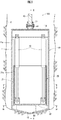
本発明のドリリングバケットは、一般的なドリリングバケットより長尺の本体バケット(長尺バケット)と、これに内蔵される内部コンテナ(内部バケット)とを備え、内部コンテナが本体バケット内を昇降可能なように構成されている。 The drilling bucket according to the present invention includes a main body bucket (long bucket) longer than a general drilling bucket and an internal container (internal bucket) built in the main bucket, and the internal container can move up and down in the main body bucket. It is configured as follows.
〔第1の実施形態〕
以下、本発明の第1の実施形態に係るドリリングバケット100について図1から図6を参照して説明する。このドリリングバケット100は、本体バケット10内で内部コンテナ20を昇降可能とする機構として、油圧シリンダ30を用いている。
[First Embodiment]
Hereinafter, a
本体バケット10は、円筒形の胴体部(バケット胴体部)11と、胴体部11の底部に開閉自在に配置され、下側が突出する略円錐形の底蓋(バケット底蓋)12とを備えている。底蓋12には本体バケット10内に土砂を取り込むための開口部(バケット開口部)13が2つ形成されている(図3参照)。そして、底蓋12の掘削孔Aの底壁に接する部分に刃口(切削刃)14(図3参照)が設けられている。
The
掘削孔Aの底壁に底蓋12を押し付けながら回転させることで、刃口14が切削した土砂が開口部13を介して本体バケット10の内部に取り込まれる。ドリリングバケット100の押込力及び回転力は、ケリーバー40から伝達される。
By rotating the
内部コンテナ20は、円筒形の胴体部(コンテナ胴体部)21と、胴体部21の底部に開閉自在に配置され、平板状の底蓋(コンテナ底蓋)22とを備えている、内部コンテナ20の胴体部21の外径は、本体バケット10の胴体部11の内径より小径になっている。内部コンテナ20の底蓋22には、土砂を取り入れるための開口部(コンテナ開口部)23が2つ形成されている(図4参照)。
The
さらに、ドリリングバケット100には、本体バケット10の開口部13から取り込んだ土砂を内部コンテナ20の開口部23へ誘導するために、スロープ状の誘導板50が設けられている。なお、誘導板50は、ここでは、本体バケット10の底蓋12に設けられているが、内部コンテナ20の底蓋22に設けてもよい。
Further, the
本体バケット10と内部コンテナ20の底蓋12,22は、それぞれ蝶番15,25によって胴体部11,21に開閉可能に支持されている。そして、底蓋12,22がそれぞれ胴体部11,21の下方を閉じた状態を維持するための機構として係止機構(フック機構)16,26が設けられている。
The
係止機構16,26による底蓋12,22の係止を解除することによって、底蓋12,22は蝶番15,25を支点として下方に回動し、胴体部11,21の下方が外部に開放される。本体バケット10と内部コンテナ20の底蓋12,22を開放する際に、互いの底蓋12,22が干渉しないように、これらの蝶番15,25をずらして配置することが好ましい。なお、係止機構16,26は、図示しないフック動作杆等を作業者が操作することにより、係止が解除される。
By releasing the locking of the
内部コンテナ20の各開口部23には逆止板(シャッタ板)27が設けられている。逆止板27は、それぞれ蝶番28に揺動可能に設けられている。逆止板27で開口部23が閉鎖されて土砂の落下が阻止されるため、内部コンテナ20内に一旦取り込まれた土砂が本体バケット10内に逆流することはない。なお、図示しないが本体バケット10の各開口部13にも逆止板が設けられている。
Each
内部コンテナ20は、本体バケット10内に設置した2本の油圧シリンダ30によって昇降可能に構成されている。各油圧シリンダ30は、本体バケット10の胴体部11の上面に固定された上面板11bにシリンダ基部が接続され、内部コンテナ20の胴体部21の下部にロッド先端が接続されている。油圧シリンダ30は、図示しないが、地上に設置された油圧装置から供給される油圧によって伸縮動作する。
The
ケリーバー40は本体バケット10の上端中央部に連結ピン41を用いて連結されている。具体的には、本体バケット10の胴体部11の上面に固定された上面板11bの中央部に設けられた連結部17と、ケリーバー40の下端部とが、連結ピン41を用いて連結されている。これにより、ケリーバー40と本体バケット10とは一体化されており、ドリリングバケット100の掘削時の押込力及び回転力は、ケリーバー40から本体バケット10に直接伝達される。
The
図示しないが、ケリーバー40は、その上端がワイヤを介してクレーン等の楊重機に吊り下げられ、且つその中間部が楊重機に設置された油圧モータ等の駆動装置に接続されている。ケリーバー40は、駆動装置からの駆動力によって、回転可能に構成されている。
Although not illustrated, the upper end of the
なお、本体バケット10と内部コンテナ20とが独立して回転すると、油圧シリンダ30にねじれ応力が作用し、好ましくない。そこで、本体バケット10から内部コンテナ20へ回転力を伝達するための機構を設けている。
In addition, if the
ここでは、このような機構として、本体バケット10の胴体部11の内側に縦方向に延びる溝部11aを設け、内部コンテナ20の胴体部21の外側にこの溝部11aと嵌合する突出部21aを設けている。これにより、内部コンテナ20の昇降を制約することなく、本体バケット10の回転力を内部コンテナ20に伝達することができ、本体バケット10の回転に伴い内部コンテナ20も同様に回転する。
Here, as such a mechanism, a
さらに、図示しないが、油圧シリンダ30に土砂がかかって内部コンテナ20の昇降が阻害されることを防止するために、油圧シリンダ30全体又はその一部を保護部材で囲むことが好ましい。保護部材は、例えば、伸縮自在な軟質管や、蛇腹状のシートなどであればよい。また、保護部材に、本体バケット10から内部コンテナ20へ回転力を伝達するための上述した機構を設けてもよい。
Furthermore, although not shown, it is preferable to surround the entire
次に、ドリリングバケット100を用いた掘削方法について説明する。
Next, the excavation method using the
[1]まず、内部コンテナ20が最下降位置に位置する状態で、前記楊重機を操作して、ドリリングバケット100を掘削孔A内へ挿入し、掘削孔Aの底壁にドリリングバケット100を着底させる。
[1] First, with the
なお、内部コンテナ20が最下降位置に位置する状態とは、本体バケット10内の昇降可能な範囲内で内部コンテナ20が最も下降した位置に位置する状態を意味する。この状態で掘削を行うことにより、開口部13から取り込んだ土砂を誘導板50を介して開口部23から内部コンテナ20の内部に取り込むことができる。
The state in which the
[2]前記駆動装置を作動してケリーバー40を回転させながらドリリングバケット100を下降させる。そして、ドリリングバケット100を掘削孔Aの底壁に押し付けた状態で回転させる。これにより、刃口14で切削された土砂が本体バケット10の開口部13から取り込まれる。この段階では、本体バケット10の開口部13から取り込んだ土砂は、続いて取り込まれる土砂によって押し上げられ、誘導板50を経由して、開口部23を介して内部コンテナ20の内部に取り込まれる。
[2] The driving device is operated to lower the
[3]内部コンテナ20内の土砂が1回の内部コンテナ20の最大取り込み量に達したら、前記駆動装置の作動を停止させて、ドリリングバケット100の回転を停止する。そして、前記油圧機構を作動させて、図6に示すように、油圧シリンダ30を退縮させ、内部コンテナ20を最上昇位置まで上昇させる。この内部コンテナ20の上昇によって、本体バケット10の下部に空間が形成される。
[3] When the earth and sand in the
なお、内部コンテナ20が最上昇位置に位置する状態とは、本体バケット10内の昇降可能な範囲内で内部コンテナ20が最も上昇した位置に位置する状態を意味する。この状態で掘削を行うことにより、開口部13から最大限、本体バケット10の内部に土砂を取り込むことができる。
The state in which the
[4]その後、再び、前記駆動装置を作動して、ドリリングバケット100を掘削孔Aの底壁に押し付けた状態で回転させる。これにより、内部コンテナ20の上昇によって本体バケット10の下部に形成された空間内に土砂が取り込まれる。
[4] Thereafter, the driving device is operated again to rotate the
[5]本体バケット10内の土砂が1回の本体バケット10の最大取り込み量に達したら、前記駆動装置の作動を停止させて、ドリリングバケット100の回転を停止する。
[5] When the earth and sand in the
[6]前記楊重機を操作して、ドリリングバケット100を地上に引き上げる。そして、内部コンテナ20と本体バケット10との内部に取り込まれた土砂を掘削孔Aの外部に排出する。
[6] Operate the heavy machinery to lift the
土砂の排出は、まず、本体バケット10の底蓋12を開放して土砂を落下させる。次に、前記油圧機構を作動させて、油圧シリンダ30を伸長させ、内部コンテナ20を最下降位置に移動させてから底蓋22を開放して土砂を落下させる。なお、本体バケット10の内側に土砂が張り付いている場合には、このような土砂を削ぎ落としてから、内部コンテナ20を下降させる。
For discharging the earth and sand, first, the
土砂の排出が全て終了した後、内部コンテナ20の底蓋22を閉じた後、本体バケット10の底蓋12を閉じる。本体バケット10と内部コンテナ20の回転方向の位置関係は一定であるので、それぞれの底蓋12,22を閉じることによって、各開口部13,23と誘導板50とは土砂の取り込みに適した位置関係になる。
After all the earth and sand have been discharged, the
上述した[1]から[6]の作業を掘削孔Aが所望の深度に達するまで繰り返し行う。 The operations [1] to [6] are repeated until the excavation hole A reaches a desired depth.
このように、ドリリングバケット100の1回の最大掘削量は、本体バケット10の1回の最大取り込み量と内部コンテナ20の1回の最大取り込み量との和となる。
Thus, the maximum excavation amount of the
本体バケット10、内部コンテナ20ともに、土砂を取り込んで押し上げることができる高さは、通常のドリリングバケットと同程度である。そこで、通常のドリリングバケットと同じ駆動装置を用いた場合、本体バケット10の胴体部11を通常のドリリングバケットの胴体部の2倍程度の長さとし、内部コンテナ20の胴体部21を通常のドリリングバケットと同程度の長さとして、内部コンテナ20を本体バケット10の中央部以上まで上昇可能な構成とすれば、ドリリングバケット100の1回の掘削量は最大となり、最も作業効率が優れたものとなる。
Both the
以上、説明したように、内部コンテナ20が最下降位置に位置する状態において、開口部13、誘導板50、開口部23を介して内部コンテナ20内に土砂を取り入れることができるとともに、内部コンテナを最上昇位置に位置させた状態において、開口部13を介して本体バケット10内に土砂を取り入れることができる。
As described above, in the state where the
よって、従来のドリリングバケットを駆動させる駆動装置と同じ駆動装置を用いた場合には、内部コンテナ20及び本体バケット10内にともに従来と同じ高さまで土砂を取り込むことが可能となる。従って、従来と同じ駆動装置を用いた場合であっても、1回の最大掘削量を従来より多くすることが可能となる。
Therefore, when the same drive device as the drive device that drives the conventional drilling bucket is used, both the
これによって、ドリリングバケット100の昇降回数を少なくすることができ、孔壁の肌落ちやスライムの発生を減少させることができる。
As a result, the number of times the
さらに、従来のドリリングバケットに対して、本体バケット10内で昇降可能に構成された内部コンテナ20と誘導板50とを追加しただけの構成である。よって、上記特許文献1に記載された技術のように複雑な動力伝達機構を必要としない。
Furthermore, it is the structure which only added the
そして、本体バケット10及び内部コンテナ20には駆動装置の駆動力などによって定まる所定の同じ高さまで土砂を取り込むことが可能である。よって、内部コンテナ20が最上昇位置に位置するときの本体バケット10の土砂を取り込み可能な内部空間の高さ、及び内部コンテナ20の胴体部21の長さを、ともにこの所定の取り込み高さ以上とすれば、1回の最大掘削量を最大値にすることができる。そこで、本体バケット10の胴体部11の長さは、内部コンテナ20の胴体部21の長さの少なくとも2倍以上であることが好ましい。
And it is possible to take in the earth and sand to the
〔第2の実施形態〕
以下、本発明の第2の実施形態に係るドリリングバケット200について図7を参照して説明する。このドリリングバケット200は、本体バケット10内で内部コンテナ20を昇降可能とする機構がケリーバー40に伝達される力を用いている。なお、ドリリングバケット100と同様の構成については、同じ符号を用い、その説明を省略する。
[Second Embodiment]
Hereinafter, a
ケリーバー40は内部コンテナ20の上端中央部に連結ピン41を用いて連結されている。具体的には、内部コンテナ20の胴体部21の上面に固定された上面板61の中央部に設けられた連結部62と、ケリーバー40の下端部とが、連結ピン41を用いて連結されている。これにより、ケリーバー40と内部コンテナ20とは一体化されている。
The
そして、掘削時のケリーバー40からの押込力及び回転力が、内部コンテナ20を介して本体バケット10に伝達されるように構成されている。具体的には、本体バケット10の胴体部11の内側に溝部63を形成し、内部コンテナ20の胴体部21の外側に形成した突出部64を溝部63内に嵌め込むことにより、内部コンテナ20は本体バケット10に対して溝部63に沿った移動のみが可能となるように構成している。
The pushing force and rotational force from the
溝部63は、内部コンテナ20を昇降させるために垂直方向に形成された垂直溝部63aと、この垂直溝部63aの上下両端をそれぞれ始点として同方向に水平方向に伸長する2本の水平溝部63b,63cとからなり、全体としてコの字形状になっている。
The
内部コンテナ20の突出部64が水平溝部63b,63cの先端に当接することにより、内部コンテナ20が本体バケット10に対して水平溝部63b,63cの始端から先端に向う回転力及び押込力を内部コンテナ20から本体バケット10に伝達することが可能になっている。
When the protruding
下側の水平溝部63bは、内部コンテナ20の下端が本体バケット10の下端付近となる高さである最下降位置になるように設定されている。下側の水平溝部63bの先端に本体バケット10の突出部64が位置しているとき、本体バケット10の開口部13から取り込まれた土砂は誘導板50を経由して開口部23から内部コンテナ20内に取り込むことができる。
The lower
上側の水平溝部63cは、内部コンテナ20の上端が本体バケット10の上端付近となる高さである最上昇位置になるように設定されている。内部コンテナ20がこの最上昇位置に位置するとき、本体バケット10は1回の最大取り込み量まで土砂を取り込むことができる。
The upper
次に、ドリリングバケット200を用いた掘削方法について説明する。
Next, an excavation method using the
[1]まず、内部コンテナ20が最下降位置に位置する状態で、前記楊重機を操作して、ドリリングバケット200を掘削孔A内へ挿入し、掘削孔Aの底壁にドリリングバケット200を着底させる。
[1] First, with the
[2]前記駆動装置を作動してケリーバー40を回転させながらドリリングバケット200を下降させる。そして、ドリリングバケット200を掘削孔Aの底壁に押し付けた状態で回転させる。これにより、切削された土砂が本体バケット10の開口部13から取り込まれる。この段階では、本体バケット10の開口部13から取り込んだ土砂は、続いて取り込まれる土砂によって押し上げられ、誘導板50を経由して、開口部23を介して内部コンテナ20の内部に取り込まれる。
[2] The driving device is operated to lower the
[3]内部コンテナ20内の土砂が1回の内部コンテナ20の最大取り込み量に達したら、前記駆動装置の作動を停止させて、ドリリングバケット200の回転を停止する。そして、前記駆動装置を作動して、ケリーバー40を逆回転させ、本体バケット10の突出部64が下側の水平溝部63bの始端(すなわち、垂直溝部63aの下端)に位置させた後、前記駆動装置の作動を停止させる。
[3] When the earth and sand in the
そして、前記揚重機を操作して、ケリーバー40を上昇させて、本体バケット10の突出部64を垂直溝部63aの上端(すなわち、上側の水平溝部63cの始端)に位置させる。その後、前記駆動装置を作動して、ケリーバー40を回転させ、本体バケット10の突出部64を上側の水平溝部63cの先端に位置させた後、前記駆動装置の作動を停止させる。これにより、内部コンテナ20は最上昇位置に位置する。この内部コンテナ20の上昇によって、本体バケット10の下部に空間が形成される。
Then, the lifting machine is operated to raise the
[4]その後、再び、前記駆動装置を作動して、ドリリングバケット200を掘削孔Aの底壁に押し付けた状態で回転させる。これにより、内部コンテナ20の上昇によって本体バケット10の下部に形成された空間内に土砂が取り込まれる。
[4] After that, the driving device is operated again to rotate the
[5]本体バケット10内の土砂が1回の本体バケット10の最大取り込み量に達したら、前記駆動装置の作動を停止させて、ドリリングバケット200の回転を停止する。
[5] When the earth and sand in the
[6]前記楊重機を操作して、ドリリングバケット200を地上に引き上げる。そして、内部コンテナ20と本体バケット10との内部に取り込まれた土砂を掘削孔Aの外部に排出する。
[6] The heavy machinery is operated to lift the
土砂の排出は、まず、本体バケット10の底蓋12を開放して土砂を落下させる。次に、前記駆動装置を作動して、ケリーバー40を逆回転させ、本体バケット10の突出部64を上側の水平溝部63cの始端(すなわち、垂直溝部63aの上端)に位置させた後、前記駆動装置の作動を停止させる。
For discharging the earth and sand, first, the
そして、前記揚重機を操作して、ケリーバー40を下降させて、本体バケット10の突出部64を水平溝部63aの下端(すなわち、下側の水平溝部63bの始端)に位置させる。その後、前記駆動装置を作動して、ケリーバー40を回転させ、本体バケット10の突出部64を下側の水平溝部63cの先端に位置させた後、前記駆動装置の作動を停止させる。これにより、内部コンテナ20は最下降位置に位置する。その後、底蓋22を開放して内部コンテナ20から土砂を落下させる。
Then, the lifting machine is operated to lower the
なお、内部コンテナ20内の土砂を排出する際には、地上に設置した架台で本体バケット10を支持してから内部コンテナ20を下降させることが好ましい。
In addition, when discharging the earth and sand in the
土砂の排出が全て終了した後、内部コンテナ20の底蓋22を閉じた後、本体バケット10の底蓋12を閉じる。本体バケット10と内部コンテナ20の回転方向の位置関係は一定であるので、それぞれの底蓋12,22を閉じることによって、各開口部13,23と誘導板50とは土砂の取り込みに適した位置関係になる。
After all the earth and sand have been discharged, the
上述した[1]から[6]の作業を掘削孔Aが所望の深度に達するまで繰り返し行う。 The operations [1] to [6] are repeated until the excavation hole A reaches a desired depth.
このように、ドリリングバケット200の1回の最大掘削量は、本体バケット10の1回の最大取り込み量と内部コンテナ20の1回の最大取り込み量との和となる。
Thus, the maximum excavation amount of one
本体バケット10、内部コンテナ20ともに、土砂を取り込んで押し上げることができる高さは、通常のドリリングバケットと同程度である。そこで、通常のドリリングバケットと同じ駆動装置を用いた場合、本体バケット10の胴体部11を通常のドリリングバケットの胴体部の2倍程度の長さとし、内部コンテナ20の胴体部21を通常のドリリングバケットと同程度の長さとして、内部コンテナ20を本体バケット10の中央部以上まで上昇可能な構成とすれば、ドリリングバケット200の1回の掘削量は最大となり、最も作業効率が優れたものとなる。
Both the
以上、説明したように、内部コンテナ20が最下降位置に位置する状態において、開口部13、誘導板50、開口部23を介して内部コンテナ20内に土砂を取り入れることができるとともに、内部コンテナを最上昇位置に位置させた状態において、開口部13を介して本体バケット10内に土砂を取り入れることができる。
As described above, in the state where the
よって、従来のドリリングバケットを駆動させる駆動装置と同じ駆動装置を用いた場合には、内部コンテナ20及び本体バケット10内にともに従来と同じ高さまで土砂を取り込むことが可能となる。従って、従来と同じ駆動装置を用いた場合であっても、1回の最大掘削量を従来より多くすることが可能となる。
Therefore, when the same drive device as the drive device that drives the conventional drilling bucket is used, both the
これによって、ドリリングバケット200の昇降回数を少なくすることができ、孔壁の肌落ちやスライムの発生を減少させることができる。
As a result, the number of times the
さらに、従来のドリリングバケットに対して、本体バケット10内で昇降可能に構成された内部コンテナ20と誘導板50とを追加しただけの構成である。よって、上記特許文献1に記載された技術のように複雑な動力伝達機構を必要としない。
Furthermore, it is the structure which only added the
そして、内部コンテナ20及び本体バケット10には駆動装置の駆動力などによって定まる所定の同じ高さまで土砂を取り込むことが可能である。よって、本体バケット10の胴体部11の長さは、内部コンテナ20の胴体部21の長さの少なくとも2倍以上であることが好ましい。
And it is possible to take the earth and sand into the
なお、溝部を内部コンテナ20の外側に、突出部を本体バケット10の内側にそれぞれ設けてもよい。また、溝部内に土砂が入らないように保護部材を設けてもよい。
The groove portion may be provided outside the
10…本体バケット、 11…胴体部(バケット胴体部)、 11a…溝部、 12…底蓋(バケット底蓋)、 13…開口部(バケット開口部)、 14…刃口(切削刃)、 20…内部コンテナ、 21…胴体部(コンテナ胴体部)、 21a…突出部、 22…底蓋(コンテナ底蓋)、 23…開口部(コンテナ開口部)、 30…油圧シリンダ、 40…ケリーバー、 41…連結ピン、 50…誘導板、 63…溝部、 63a…垂直溝部、 63b…下側の水平溝部、 63c…上側の水平溝部、 64…突出部、 100,200…ドリリングバケット、 A…掘削孔。
DESCRIPTION OF
Claims (5)
本体バケットと、前記本体バケットに内蔵され、前記本体バケット内で昇降可能に構成された内部コンテナとからなり、
前記本体バケットは、円筒形のバケット胴体部と、前記バケット胴体部の底部に開閉自在に設けられたバケット底蓋と、前記バケット底蓋に形成されたバケット開口部とを備え、
前記内部コンテナは、前記バケット胴体部よりも小径の円筒形のコンテナ胴体部と、前記コンテナ胴体部の底部に開閉自在に設けられたコンテナ底蓋と、前記コンテナ底蓋に形成されたコンテナ開口部とを備え、
前記内部コンテナが最下降位置に位置する状態において、前記バケット底蓋を掘削孔の底壁に押し付けた状態で回転したときに前記バケット開口部から取り込んだ土砂を前記コンテナ開口部まで誘導する誘導板が設けられていることを特徴とするドリリングバケット。 A drilling bucket for taking excavated earth and sand into the bucket,
It consists of a main body bucket and an internal container built in the main body bucket and configured to be movable up and down in the main body bucket,
The main body bucket includes a cylindrical bucket body portion, a bucket bottom lid provided at the bottom of the bucket body portion so as to be freely opened and closed, and a bucket opening formed in the bucket bottom lid,
The inner container includes a cylindrical container body portion having a smaller diameter than the bucket body portion, a container bottom lid provided at the bottom of the container body portion so as to be openable and closable, and a container opening formed in the container bottom lid And
A guide plate for guiding the earth and sand taken from the bucket opening to the container opening when the bucket is rotated with the bucket bottom lid pressed against the bottom wall of the excavation hole in a state where the inner container is at the lowest position Is provided with a drilling bucket.
前記内部コンテナが最下降位置に位置する状態で、前記ドリリングバケットを掘削孔内へ挿入する工程と、
前記ドリリングバケットを前記掘削孔の底壁に押し付けた状態で回転させて、前記本体バケットの底部に形成されたバケット開口部から取り込んだ土砂を、誘導板を経由して、前記内部コンテナの底部に形成されたコンテナ開口部から前記内部コンテナ内に取り込む工程と、
前記ドリリングバケットの回転を停止し、内部に土砂を取り込んだ前記内部コンテナを上方に移動させる工程と、
前記ドリリングバケットを前記掘削孔の底壁に押し付けた状態で回転させて、前記内部コンテナが上方に移動したことにより前記本体バケットの内部下方に形成された空間内に、前記バケット開口部から土砂を取り込む工程と、
前記ドリリングバケットの回転を停止し、前記本体バケット及び前記内部コンテナの内部に取り込んだ土砂を前記掘削孔の外部へ排出する工程とを含むことを特徴とする掘削方法。 A drilling method of a drilling hole using a drilling bucket comprising a main body bucket and an internal container built in the main body bucket and configured to be movable up and down in the main body bucket,
Inserting the drilling bucket into the excavation hole in a state where the inner container is located at the lowest position;
The drilling bucket is rotated in a state where it is pressed against the bottom wall of the excavation hole, and the earth and sand taken from the bucket opening formed at the bottom of the main body bucket is transferred to the bottom of the internal container via a guide plate. Taking into the internal container from the formed container opening;
Stopping the rotation of the drilling bucket and moving the internal container that has taken in the soil upwards;
The drilling bucket is rotated in a state where it is pressed against the bottom wall of the excavation hole, and the sand is discharged from the bucket opening into the space formed inside the main body bucket by moving the internal container upward. Capture process;
A step of stopping the rotation of the drilling bucket and discharging the earth and sand taken into the main body bucket and the inner container to the outside of the excavation hole.
Priority Applications (1)
| Application Number | Priority Date | Filing Date | Title |
|---|---|---|---|
| JP2011225467A JP5873679B2 (en) | 2011-10-13 | 2011-10-13 | Drilling bucket and excavation method using drilling bucket |
Applications Claiming Priority (1)
| Application Number | Priority Date | Filing Date | Title |
|---|---|---|---|
| JP2011225467A JP5873679B2 (en) | 2011-10-13 | 2011-10-13 | Drilling bucket and excavation method using drilling bucket |
Publications (2)
| Publication Number | Publication Date |
|---|---|
| JP2013087415A JP2013087415A (en) | 2013-05-13 |
| JP5873679B2 true JP5873679B2 (en) | 2016-03-01 |
Family
ID=48531629
Family Applications (1)
| Application Number | Title | Priority Date | Filing Date |
|---|---|---|---|
| JP2011225467A Expired - Fee Related JP5873679B2 (en) | 2011-10-13 | 2011-10-13 | Drilling bucket and excavation method using drilling bucket |
Country Status (1)
| Country | Link |
|---|---|
| JP (1) | JP5873679B2 (en) |
Family Cites Families (4)
| Publication number | Priority date | Publication date | Assignee | Title |
|---|---|---|---|---|
| JPH0679893U (en) * | 1993-04-28 | 1994-11-08 | 日本基礎技術株式会社 | Drilling bucket |
| JPH07116904B2 (en) * | 1993-08-27 | 1995-12-18 | 明和機械株式会社 | Excavation bucket for drilling holes |
| JPH07293174A (en) * | 1994-04-20 | 1995-11-07 | Mitsubishi Constr Co Ltd | Drilling bucket for earth drilling construction method |
| JPH07301077A (en) * | 1994-05-09 | 1995-11-14 | Mitsubishi Constr Co Ltd | General purpose drilling bucket for earth drill construction method |
-
2011
- 2011-10-13 JP JP2011225467A patent/JP5873679B2/en not_active Expired - Fee Related
Also Published As
| Publication number | Publication date |
|---|---|
| JP2013087415A (en) | 2013-05-13 |
Similar Documents
| Publication | Publication Date | Title |
|---|---|---|
| US4202416A (en) | Method and apparatus for sinking a cased borehole for producing cased pile foundations | |
| JP2017053167A (en) | Existing pile removal device | |
| JP6308990B2 (en) | Attachment for removing underground obstacles and method for removing underground obstacles | |
| WO2003091532A1 (en) | Drilling device for earth drill | |
| JP2006207252A (en) | Pile pull-out machine | |
| JP5873679B2 (en) | Drilling bucket and excavation method using drilling bucket | |
| JP4714724B2 (en) | Hammer grab | |
| JP2016176263A (en) | Underground obstacle removing device | |
| JP5290463B1 (en) | Hammer grabs and low-head drilling rigs | |
| JP5479943B2 (en) | Hammer grab | |
| JP3392810B2 (en) | Shaft excavator | |
| JP2010031523A (en) | Vertical shaft excavator | |
| JP2005232930A (en) | Drilling device and steel-pipe pile forming device | |
| JP3225878U (en) | Excavation bucket for drilling holes | |
| JP2001164867A (en) | Excavation device for earth drill | |
| JP6329382B2 (en) | Excavation bucket and excavation method | |
| JP2023008062A (en) | Bucket device for earth drill | |
| JP6087794B2 (en) | Hammer grab | |
| JP2530905B2 (en) | Drill bit gravel crusher | |
| JP3856739B2 (en) | Drilling bucket for earth drill | |
| JP2019218827A (en) | Underground obstacle removal device | |
| JP5046673B2 (en) | Vertical drilling equipment and excavation method | |
| JP3556803B2 (en) | Shaft excavator | |
| US2879974A (en) | Grab-type tool for sinking wells in the ground | |
| JP7449545B2 (en) | Underground object crushing and removal equipment |
Legal Events
| Date | Code | Title | Description |
|---|---|---|---|
| A621 | Written request for application examination |
Free format text: JAPANESE INTERMEDIATE CODE: A621 Effective date: 20141009 |
|
| A977 | Report on retrieval |
Free format text: JAPANESE INTERMEDIATE CODE: A971007 Effective date: 20150827 |
|
| A131 | Notification of reasons for refusal |
Free format text: JAPANESE INTERMEDIATE CODE: A131 Effective date: 20150929 |
|
| A521 | Request for written amendment filed |
Free format text: JAPANESE INTERMEDIATE CODE: A523 Effective date: 20151112 |
|
| TRDD | Decision of grant or rejection written | ||
| A01 | Written decision to grant a patent or to grant a registration (utility model) |
Free format text: JAPANESE INTERMEDIATE CODE: A01 Effective date: 20160105 |
|
| A61 | First payment of annual fees (during grant procedure) |
Free format text: JAPANESE INTERMEDIATE CODE: A61 Effective date: 20160118 |
|
| R150 | Certificate of patent or registration of utility model |
Ref document number: 5873679 Country of ref document: JP Free format text: JAPANESE INTERMEDIATE CODE: R150 |
|
| R250 | Receipt of annual fees |
Free format text: JAPANESE INTERMEDIATE CODE: R250 |
|
| LAPS | Cancellation because of no payment of annual fees |