JP5869826B2 - Ventilation rotor and stator for electric machine - Google Patents
Ventilation rotor and stator for electric machine Download PDFInfo
- Publication number
- JP5869826B2 JP5869826B2 JP2011220019A JP2011220019A JP5869826B2 JP 5869826 B2 JP5869826 B2 JP 5869826B2 JP 2011220019 A JP2011220019 A JP 2011220019A JP 2011220019 A JP2011220019 A JP 2011220019A JP 5869826 B2 JP5869826 B2 JP 5869826B2
- Authority
- JP
- Japan
- Prior art keywords
- rotor
- stator
- cooling
- stack
- electric machine
- Prior art date
- Legal status (The legal status is an assumption and is not a legal conclusion. Google has not performed a legal analysis and makes no representation as to the accuracy of the status listed.)
- Active
Links
- 238000009423 ventilation Methods 0.000 title claims description 32
- 238000001816 cooling Methods 0.000 claims description 90
- 239000002826 coolant Substances 0.000 claims description 29
- 238000004804 winding Methods 0.000 claims description 29
- 238000004891 communication Methods 0.000 claims description 11
- 125000006850 spacer group Chemical group 0.000 claims description 11
- 229910052739 hydrogen Inorganic materials 0.000 claims description 3
- 239000001257 hydrogen Substances 0.000 claims description 3
- UFHFLCQGNIYNRP-UHFFFAOYSA-N Hydrogen Chemical compound [H][H] UFHFLCQGNIYNRP-UHFFFAOYSA-N 0.000 claims description 2
- 239000004020 conductor Substances 0.000 description 5
- 239000012809 cooling fluid Substances 0.000 description 5
- RYGMFSIKBFXOCR-UHFFFAOYSA-N Copper Chemical compound [Cu] RYGMFSIKBFXOCR-UHFFFAOYSA-N 0.000 description 4
- 238000005273 aeration Methods 0.000 description 4
- XAGFODPZIPBFFR-UHFFFAOYSA-N aluminium Chemical compound [Al] XAGFODPZIPBFFR-UHFFFAOYSA-N 0.000 description 4
- 229910052782 aluminium Inorganic materials 0.000 description 4
- 229910052802 copper Inorganic materials 0.000 description 4
- 239000010949 copper Substances 0.000 description 4
- 238000005520 cutting process Methods 0.000 description 3
- 238000000034 method Methods 0.000 description 3
- 238000013022 venting Methods 0.000 description 3
- 238000004519 manufacturing process Methods 0.000 description 2
- 239000003302 ferromagnetic material Substances 0.000 description 1
- 239000012530 fluid Substances 0.000 description 1
- 150000002431 hydrogen Chemical class 0.000 description 1
- 238000003475 lamination Methods 0.000 description 1
- XLYOFNOQVPJJNP-UHFFFAOYSA-N water Substances O XLYOFNOQVPJJNP-UHFFFAOYSA-N 0.000 description 1
Images


Classifications
-
- H—ELECTRICITY
- H02—GENERATION; CONVERSION OR DISTRIBUTION OF ELECTRIC POWER
- H02K—DYNAMO-ELECTRIC MACHINES
- H02K1/00—Details of the magnetic circuit
- H02K1/06—Details of the magnetic circuit characterised by the shape, form or construction
- H02K1/12—Stationary parts of the magnetic circuit
- H02K1/20—Stationary parts of the magnetic circuit with channels or ducts for flow of cooling medium
-
- H—ELECTRICITY
- H02—GENERATION; CONVERSION OR DISTRIBUTION OF ELECTRIC POWER
- H02K—DYNAMO-ELECTRIC MACHINES
- H02K1/00—Details of the magnetic circuit
- H02K1/06—Details of the magnetic circuit characterised by the shape, form or construction
- H02K1/22—Rotating parts of the magnetic circuit
- H02K1/32—Rotating parts of the magnetic circuit with channels or ducts for flow of cooling medium
-
- H—ELECTRICITY
- H02—GENERATION; CONVERSION OR DISTRIBUTION OF ELECTRIC POWER
- H02K—DYNAMO-ELECTRIC MACHINES
- H02K1/00—Details of the magnetic circuit
- H02K1/06—Details of the magnetic circuit characterised by the shape, form or construction
- H02K1/22—Rotating parts of the magnetic circuit
- H02K1/27—Rotor cores with permanent magnets
- H02K1/2706—Inner rotors
- H02K1/272—Inner rotors the magnetisation axis of the magnets being perpendicular to the rotor axis
- H02K1/274—Inner rotors the magnetisation axis of the magnets being perpendicular to the rotor axis the rotor consisting of two or more circumferentially positioned magnets
- H02K1/2753—Inner rotors the magnetisation axis of the magnets being perpendicular to the rotor axis the rotor consisting of two or more circumferentially positioned magnets the rotor consisting of magnets or groups of magnets arranged with alternating polarity
- H02K1/276—Magnets embedded in the magnetic core, e.g. interior permanent magnets [IPM]
- H02K1/2766—Magnets embedded in the magnetic core, e.g. interior permanent magnets [IPM] having a flux concentration effect
-
- H—ELECTRICITY
- H02—GENERATION; CONVERSION OR DISTRIBUTION OF ELECTRIC POWER
- H02K—DYNAMO-ELECTRIC MACHINES
- H02K9/00—Arrangements for cooling or ventilating
- H02K9/02—Arrangements for cooling or ventilating by ambient air flowing through the machine
- H02K9/04—Arrangements for cooling or ventilating by ambient air flowing through the machine having means for generating a flow of cooling medium
- H02K9/06—Arrangements for cooling or ventilating by ambient air flowing through the machine having means for generating a flow of cooling medium with fans or impellers driven by the machine shaft
Description
本明細書で記載される主題は、全体的に電動機械に関し、より詳細には、通気通路を備えた積層ロータを有する電動機械に関する。 The subject matter described herein relates generally to electric machines, and more particularly, to electric machines having a laminated rotor with vent passages.
現在、電動機械を冷却する公知の方法は、スペーサを用いてロータ及び/又はステータを通気することを含む。一般に、コアは積層体を含むことができ、スペーサは、積層パケットを分離するため離散間隔で取り付けることができる。スペーサは、I形ビーム、ブロック、又はパケットとして構成することができ、ここでI形ビーム及びブロックは、単に、積層体を離間して配置し、積層体間の冷却空気の流れを可能にするよう機能する。スペーサパケットは、中央ボアを含むことができ、該中央ボアは、間に配置された各積層体のアパーチャと連通しており、従って、積層体を通って横方向に冷却空気を流すことができる。上記の方法の1つの欠点は、各積層体が該積層体間にスペーサを固定することが必要となり、これによってより複雑になり、製造コストが大幅に増加することである。 Currently, known methods for cooling electric machines include venting the rotor and / or stator with spacers. In general, the core can include a stack, and the spacers can be attached at discrete intervals to separate the stacked packets. The spacers can be configured as I-beams, blocks, or packets, where the I-beams and blocks simply place the stacks apart and allow cooling air flow between the stacks. It works as follows. The spacer packet can include a central bore that communicates with the apertures of each stack disposed therebetween, and thus allows cooling air to flow laterally through the stack. . One drawback of the above method is that each laminate requires that spacers be secured between the laminates, which makes it more complicated and greatly increases manufacturing costs.
本発明の1つの態様によれば、積層ロータが電動機械に提供される。ロータは、複数の冷却アパーチャを有する少なくとも1つの端部フランジと、複数の冷却アパーチャを有する少なくとも1つのロータ内側通気積層体とを含む。少なくとも1つのロータ外側通気積層体は、第1の複数の半径方向に向いたロータ通気スロットと連通した複数の冷却アパーチャを有する。端部フランジ、ロータ内側通気積層体、及びロータ外側通気積層体が全体としてロータ積層体スタックに構成され、複数のロータ冷却アパーチャが、冷却媒体の流れのためのほぼ軸方向の冷却通路を形成する。 According to one aspect of the invention, a laminated rotor is provided for an electric machine. The rotor includes at least one end flange having a plurality of cooling apertures and at least one rotor inner vent laminate having a plurality of cooling apertures. The at least one rotor outer vent stack has a plurality of cooling apertures in communication with the first plurality of radially oriented rotor vent slots. The end flange, the rotor inner ventilation laminate, and the rotor outer ventilation laminate are generally configured in a rotor laminate stack, and the plurality of rotor cooling apertures form a substantially axial cooling passage for cooling medium flow. .
本発明の別の態様によれば、積層ステータが電動機械に提供される。ステータは、ステータ巻線用の複数のスロットを有する少なくとも1つの端部積層体と、第1の複数のステータ冷却アパーチャと連通した第1の複数のスロットを有する少なくとも1つの第1の積層体とを含む。ステータ巻線は、第1の複数のスロット内に包含される。少なくとも1つの第2の積層体は、第2の複数のスロットと、第1の複数の冷却アパーチャと連通した第2の複数の冷却アパーチャとを有する。ステータ巻線はまた、第2の複数のスロット内に包含される。端部積層体、第1の積層体及び第2の積層体が全体としてステータ積層体スタックに構成される。複数のスロットがほぼ半径方向冷却通路を形成し、第1及び第2の複数の冷却アパーチャが、冷却媒体の流れのためのほぼ軸方向の冷却通路を形成する。 According to another aspect of the invention, a laminated stator is provided for an electric machine. The stator includes at least one end stack having a plurality of slots for stator windings, and at least one first stack having a first plurality of slots in communication with the first plurality of stator cooling apertures. including. The stator winding is contained within the first plurality of slots. The at least one second stack includes a second plurality of slots and a second plurality of cooling apertures in communication with the first plurality of cooling apertures. The stator winding is also contained within the second plurality of slots. The end laminate, the first laminate, and the second laminate are configured as a whole in the stator laminate stack. The plurality of slots form a substantially radial cooling passage, and the first and second plurality of cooling apertures form a substantially axial cooling passage for cooling medium flow.
本発明の更に別の態様によれば、ロータ及びステータを有する電動機械が提供される。電動機械は、複数のロータ冷却アパーチャを有する少なくとも1つのロータ端部フランジと、複数のロータ冷却アパーチャを有する少なくとも1つのロータ内側通気積層体と、第1の複数の半径方向に向いたロータ通気スロットと連通した複数のロータ冷却アパーチャを有する少なくとも1つのロータ外側通気積層体とを含む。ステータは、ステータ巻線用の複数のスロットを有する少なくとも1つのステータ端部積層体と、第1の複数のステータ冷却アパーチャと連通した第1の複数のスロットを有する少なくとも1つの第1のステータ積層体とを含み、ステータ巻線は、第1の複数のスロット内に包含される。少なくとも1つの第2のステータ積層体は、第2の複数のスロットと、第1の複数のステータ冷却アパーチャと連通した第2の複数のステータ冷却アパーチャとを含み、ステータ巻線は、第2の複数のスロット内に包含される。ロータ端部フランジ、ロータ内側通気積層体、及びロータ外側通気積層体は、全体としてロータ積層体スタックに構成され、複数のロータ冷却アパーチャが、冷却媒体の流れのためのほぼ軸方向のロータ冷却通路を形成する。ステータ端部積層体、第1のステータ積層体、及び第2のステータ積層体が全体としてステータ積層体スタックに構成され、複数のスロットがほぼ半径方向エリ客通路を形成し、第1及び第2の複数のステータ冷却アパーチャが、冷却媒体の流れのためのほぼ軸方向ステータ冷却通路を形成する。 According to yet another aspect of the present invention, an electric machine having a rotor and a stator is provided. The electric machine includes: at least one rotor end flange having a plurality of rotor cooling apertures; at least one rotor inner ventilation stack having a plurality of rotor cooling apertures; and a first plurality of radially oriented rotor ventilation slots. At least one rotor outer ventilation laminate having a plurality of rotor cooling apertures in communication therewith. The stator includes at least one stator end stack having a plurality of slots for stator windings and at least one first stator stack having a first plurality of slots in communication with the first plurality of stator cooling apertures. And the stator winding is contained within the first plurality of slots. The at least one second stator stack includes a second plurality of slots and a second plurality of stator cooling apertures in communication with the first plurality of stator cooling apertures, the stator winding comprising a second plurality of stator windings Contained within multiple slots. The rotor end flange, the rotor inner vent laminate, and the rotor outer vent laminate are generally configured in a rotor laminate stack, wherein the plurality of rotor cooling apertures are substantially axial rotor cooling passages for coolant flow. Form. The stator end stack, the first stator stack, and the second stator stack are configured as a whole in the stator stack, and the plurality of slots form a substantially radial passage, and the first and second The plurality of stator cooling apertures form a substantially axial stator cooling passage for cooling medium flow.
本発明の1つの態様は、電動機械の冷却装置に関し、該電動機械は、積層体を通る冷却流体の層流及び/又は乱流の両方をもたらすような寸法及び構成にされた、無間隔配置の(間隔なしで配置された)積層体(ラミネーション)の積層コアを含む。このようにすると、積層体間のスペーサの固定を排除することで製造コストが大幅に低減される。電動機械は、発電器、モータ、或いは、機械エネルギーを電気エネルギーに又は電気エネルギーを機械エネルギーに変換するあらゆる装置を含むことができる。 One aspect of the present invention relates to a cooling device for an electric machine that is dimensioned and configured to provide both laminar and / or turbulent flow of cooling fluid through the stack. A laminate core (lamination) of the laminate (arranged without spacing). If it does in this way, manufacturing cost will be reduced significantly by eliminating fixation of the spacer between laminated bodies. An electric machine can include a generator, a motor, or any device that converts mechanical energy into electrical energy or electrical energy into mechanical energy.
図1を参照すると、本発明の1つの態様による積層ロータが全体的に符号100で示されている。この実施形態において、積層ロータ100は、1つ又はそれ以上の端部フランジ102と、複数のロータ内側通気積層体104と、複数のロータ外側通気積層体106と、ロータ中央積層体108とを含む。図示のように、端部フランジ102、ロータ内側通気積層体104、ロータ外側通気積層体106、及びロータ中央積層体108の各々は、その間に冷却流体の流れを形成するどのようなスペーサも無い状態で互いに隣接して配置される。勿論、積層体のグループは、軸方向及び半径方向冷却通路により定められる領域以外は、冷却流体の流れに対して全体的に有孔性でないように全体として接着及び/又は密閉することができる。従って、本明細書で用いる場合のスペーサ及び無間隔配置関係という用語は、積層コア100の接着又は密閉状態を意味するものではない。また、端部フランジ102、ロータ内側通気積層体104、ロータ外側通気積層体106、及びロータ中央積層体108の各々は、ほぼ円盤状の外側構成を各々備えることができ、従って、その各々は、外径に対して比較的小さい幅を有することを理解されたい。更に、端部フランジ102、ロータ内側通気積層体104、ロータ外側通気積層体106、及びロータ中央積層体108の1つ又はそれ以上は、強磁性材料を含むことができ、この強磁性材料は、レーザビーム又は高圧水のような様々な切断手段を用いて型抜き加工及び/又は切断加工することができる。
Referring to FIG. 1, a laminated rotor according to one aspect of the present invention is indicated generally at 100. In this embodiment, the laminated
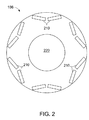
ここで図2から4を参照すると、各ロータ内側通気積層体104、ロータ外側通気積層体106、及びロータ中央積層体108は、銅又はアルミニウム(図示せず)などの導電性材料もしくは永久磁石を一般に含む複数のアパーチャを備える。図示のように、各端部フランジ102、ロータ内側通気積層体104、ロータ外側通気積層体106、及びロータ中央積層体108は、発電器又はモータシャフト(図示せず)に装着するための中央アパーチャ220を備えることができる。図示していないが、積層体は、ロータシャフト101上でキーを係合するキー溝を含むよう構成することができる。第1の複数の軸方向冷却アパーチャ230は、冷却目的で設けられ、中央アパーチャ220から円周方向及び半径方向に間隔を置いて配置される。第2の複数の軸方向冷却アパーチャ240は、冷却目的で設けられ、中央アパーチャ220から円周方向及び半径方向に間隔を置いて配置される。端部フランジ102はまた、冷却アパーチャ230及び240を含むことができる。ファン(図示せず)は、回転軸線(すなわち、軸方向軸線)に対してほぼ平行な方向でアパーチャ230及び240を通過する冷却流体の層流及び/又は乱流を生成するのに利用することができる。しかしながら、ロータは、電動機械を冷却するのに好適な圧力及び流れ特性を提供するよう構成することができる。これにより外部ファン又はシャフト装着ファンの必要性が低減又は排除される。
Referring now to FIGS. 2-4, each rotor
一部の用途において、中央積層体108は通気孔又はスロットが無く、両頭通気機械が図1に示される。しかしながら、単頭通気機械においては、中央積層体108は、端部積層体102の位置の一方に移動させることができる点は理解される。この場合には、端部積層体の一方は、取り除いて中央積層体と置き換えられることになる。全ての用途において、端部積層体は、アパーチャ210を含むことができる。中央積層体108は、特定の用途における要求に応じて半径方向及び/又は軸方向通気スロットを含むことができる。
In some applications, the
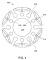
図4において、ロータ外側通気積層体106はまた、冷却アパーチャに接続された半径方向通気スロットを含む。冷却アパーチャ230は、半径方向通気スロット242に接続されてこれと連通する。通気スロット232及び242は、冷却アパーチャ230、240それぞれから半径方向外向きに延びる。図示のように、通気スロット242はほぼ極中心線を通って延びることができ、通気スロット232はほぼ極中心線間を延びる。全ての積層体が共にスタックされると、冷却アパーチャ230及び240はほぼ軸方向冷却通路を形成し、通気スロットはほぼ半径方向冷却スロット又は通路を形成する。
In FIG. 4, the rotor
軸方向から半径方向平面上に見たときに、冷却アパーチャは円形断面を有して図示され、通気アパーチャはほぼ矩形断面を有して図示されているが、冷却アパーチャ及び通気スロットには、好適な構造的支持及び流体流れを提供するあらゆる好適な幾何学的構成を利用することができる点は理解されるであろう。加えて、本発明の実施においてあらゆる好適な数の冷却アパーチャ及び通気スロットを利用してもよい点は理解されるであろう。 When viewed from an axial direction to a radial plane, the cooling aperture is illustrated with a circular cross-section and the vent aperture is illustrated with a generally rectangular cross-section, but is suitable for the cooling aperture and vent slot. It will be appreciated that any suitable geometric configuration that provides a good structural support and fluid flow can be utilized. In addition, it will be appreciated that any suitable number of cooling apertures and vent slots may be utilized in the practice of the present invention.
図5は、代替のロータ内側通気積層体504の端面図を示している。積層体504は、軸方向アパーチャ530、屈曲アパーチャ510、及び中央アパーチャ520を含む。屈曲アパーチャ510は、一般に、永久磁石、或いは銅又はアルミニウム(図示せず)などの導電性材料を包含する。中央アパーチャ520は、発電器又はモータシャフト(図示せず)に取り付けるために使用される。冷却アパーチャ530は、冷却目的で設けられ、中央アパーチャ520から円周方向及び半径方向に間隔を置いて配置される。
FIG. 5 shows an end view of an alternative rotor
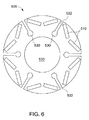
図6は、代替のロータ外側通気積層体606の端面図を示す。積層体606は、軸方向冷却アパーチャ530、半径方向通気スロット532、屈曲アパーチャ510、及び中央アパーチャ520を含む。冷却アパーチャ530は、冷却目的で設けられ、中央アパーチャ520から円周方向及び半径方向に間隔を置いて配置される。冷却アパーチャ530は、半径方向通気スロット532に接続されてこれと連通する。通気スロット532は、冷却アパーチャ530から半径方向外向きに延びており、ほぼ極中心線間に延びる。全ての積層体が共にスタックされると、冷却アパーチャ530はほぼ軸方向の冷却通路を形成し、通気スロット532は、ほぼ半径方向冷却スロット又は通路を形成する。
FIG. 6 shows an end view of an alternative rotor
積層体504及び606は、通気孔又はスロットの無い中央積層体108及び端部積層体102と共に用いることができ、両頭通気機械において、中央積層体108は、積層体スタックのほぼ中間に位置付けられることになる。しかしながら、中央積層体108は、単頭通気機械においては端部積層体102の位置の一方に移動させることができる点は理解されたい。この場合には、端部積層体の一方は、取り除いて中央積層体と置き換えられることになる。全ての用途において、端部積層体は、アパーチャ210、510を含むことができる。
図7は、本発明の1つの態様による積層ロータ700の斜視図を示す。積層ロータ700は、1つ又はそれ以上の端部フランジ702、複数のロータ内側通気積層体704、複数のロータ外側通気積層体706、及びロータ中央積層体708を含む。端部フランジ702、複数のロータ内側通気積層体704、複数のロータ外側通気積層体706、及びロータ中央積層体708の構成は、端部フランジ102、ロータ内側通気積層体104、ロータ外側通気積層体106、及びロータ中央積層体108それぞれと同様とすることができる。しかしながら、ロータ中央積層体708は、一部の用途において望ましいとすることができる、半径方向スロット232、242及び/又は軸方向通気通路230、240を含むことができる。
FIG. 7 illustrates a perspective view of a
図示のように、端部フランジ102、ロータ内側通気積層体104、ロータ外側通気積層体106、及びロータ中央積層体108の各々は、従来技術において設けられているように、その間に冷却流体の流れを形成するどのようなスペーサも無い状態で互いに隣接して配置される。1つ又はそれ以上の軸方向ファン750は、ロータシャフト101上に配置され、冷却媒体をロータ積層体に配向する。両頭通気機械(図示のような)において、中央積層体708は、積層体スタックのほぼ中間に配置される。また、ファン750は、積層体スタックの両端に配置されることになる。しかしながら、中央積層体708は、単頭通気機械においては端部積層体702の位置の一方に移動させることができる点は理解されたい。この場合には、端部積層体の一方は、取り除いて中央積層体と置き換えられることになる。
As shown, each of the
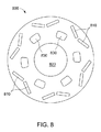
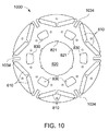
図8から11は、本発明の1つの態様による、電動機械において使用できる一連の積層体を示している。図8は、永久磁石、又は銅もしくはアルミニウム(図示せず)などの導電性材料を一般に包含する複数のアパーチャ810を有する第1の積層体(又はロータ内側通気積層体)800を示している。1つの態様において、導電性材料は、ロータ巻線又は界磁として使用される。中央アパーチャ820は、発電器又はロータシャフト(図示せず)に装着するために使用される。積層体は、ロータシャフト上でキーを係合するキー溝821を含むように構成することができる。第1の複数の軸方向冷却アパーチャ830は、冷却目的で設けられ、中央アパーチャ820から円周方向及び半径方向に間隔を置いて配置される。
8-11 illustrate a series of laminates that can be used in an electric machine according to one aspect of the present invention. FIG. 8 shows a first laminate (or rotor inner vent laminate) 800 having a plurality of
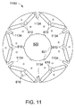
図9は、冷却アパーチャ830と連通した半径方向通気スロット932を含む第2の積層体(又はロータ外側通気積層体)900を示している。図10は、半径方向通気スロット1034を有する第3の積層体1000を示す。図11は、半径方向通気スロット1134を有する第4の積層体1100を示し、両頭通気機械の積層体スタックの中間において、或いは、単頭機械の一方端において用いることができる。軸方向冷却アパーチャ830は、軸方向冷却通路を形成し、通気スロット932、1034、及び1134は、ほぼ半径方向冷却通路を形成する。
FIG. 9 illustrates a second stack (or rotor outer vent stack) 900 that includes a
図12は、図8から11の積層体を利用する電動機械のロータ又は界磁1200の一部を示している。積層体800、900、1000、及び1100は、冷却媒体(例えば、空気又は水素、その他)がアパーチャ830を通って軸方向に流れ(全体的に矢印で示される)、次いで、半径方向上方に通気スロット932及び1034を通って流れるように配列することができる。スロット932及び1034の接合部において流れが転回し、スロット1034の頂部から流出するまで半径方向及び軸方向の両方で乱流が生成され、又は流れることができる。第4の積層体は、半径方向通気口又はスロットとして機能するスロット1134を除き、空気流の更なる軸方向移動を実質的に阻止する機能を果たす。両頭機械において、端部フランジ102、702は、積層体スタックの端部に配置することができる。図12は、両頭機械用のロータの約半分を示しており、明瞭にするために端部フランジ及び巻線は省略され、通常は第4の積層体が積層体スタックの中央又は中間付近に配置されている。単頭機械において、1つのフランジを一方端に配置することができ、第4の積層体は対向する端部に配置することができる。一部の用途において、積層体800は排除され、追加の積層体900及び1000と置き換えることができる。
FIG. 12 shows a portion of a rotor or
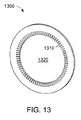
電動機械用のステータはまた、複数の積層体から構成することができる。図13は、ステータコア用の端部積層体の斜視図を示している。端部積層体1300は、銅又はアルミニウム(図示せず)などの導電性材料を包含するよう構成された複数のスロット1310を含む。中央アパーチャ1320は、ロータ(図示せず)を覆って装着するのに使用される。図14は、スロット1410及び冷却アパーチャ1430を含む第1の積層体1400の斜視図を示す。図15は、スロット1510及び冷却アパーチャ1530を含む第2の積層体1500の斜視図を示す。
A stator for an electric machine can also be composed of a plurality of laminates. FIG. 13 shows a perspective view of the end laminate for the stator core. The
図16は、ロータ1601及びステータ1602を有する電動機械の部分切り欠き斜視図を示す。ステータ1602は、1つ又はそれ以上の端部積層体1300、1つ又はそれ以上の第1の積層体1400、及び1つ又はそれ以上の第2の積層体1500のスタックから構成される。ロータ1601は、複数の半径方向冷却通路1631と連通した複数の軸方向冷却通路1630を含む。ロータ1601は、図1から12に関連して説明したように、複数の積層体のスタックから形成することができる。
FIG. 16 is a partially cutaway perspective view of an electric machine having a
ステータ積層体におけるスロット1310、1410、及び1510は、ステータ巻線1612を受け入れるように構成される。ステータ巻線1612及びスロット1310、1410、1510は、ロータ1601から半径方向外向きに流れる冷却媒体(例えば、空気又は水素)がスロット1310、1410、1510に流入し、少なくとも一部の巻線1612にわたって流れることができるように、間にスペースを備えて構成される。冷却媒体が巻線1612の傍を通過した後、スロット1410の外側半径方向部分に入り、次いで、冷却アパーチャ1430及び1530により形成される軸方向冷却通路に沿って軸方向に移動する。
図17は、図16のステータ1602の部分断面図を示す。通気スロット1410及び冷却アパーチャ1430を有する積層体1400の一部が図示されている。巻線1612は、スロット1410内に配置されるが、スペースは、冷却媒体が巻線1612にわたって通過できるように何れの側部上にも維持される。冷却媒体は、半径方向外向き(又は図17では垂直方向上向き)に流れ、次いで、アパーチャ1430及び1530によって形成されたチャンネルに沿ってページの内外に流れる。
FIG. 17 is a partial cross-sectional view of the
図18は、本発明の別の態様による、ステータ1802の部分断面図を示す。積層体におけるスロットは、巻線1612の片側だけに曝されるように構成することができる。この実施例では、第1の積層体1800は、冷却アパーチャ1830及び通気スロット1810を含む。通気スロット1810は、巻線1612の片側に沿って半径方向外向きに延びて、冷却アパーチャ1830までテーパ付きにされる。他の積層体におけるスロットは、同様の構成を有することができる。この構成は、ステータ巻線又はコイルの片側を冷却し、スロットの後部における膨張(圧力低下が小さくなることに起因して)を低減することができる。
FIG. 18 shows a partial cross-sectional view of a
図19は、ロータ1901及びステータ1902を有する電動機械1900の部分斜視図を示す。この単頭通気機械の実施例では、冷却媒体は、ファン(図示せず)などの好適な装置によってロータ軸方向通路1930を通して適用できる。冷却媒体は、通路1930に沿って軸方向に且つ半径方向通路1931を通って半径方向外向きに通過する。冷却媒体がロータ1901から流出すると、ステータ1902内の半径方向通路1942に流入する。次に、冷却媒体は、軸方向通路1940に流入し、ステータから流出するまで軸方向に移動する。通路は、ロータ及びステータを含む積層体のスタック内で種々のアパーチャ及びスロットにより形成される。
FIG. 19 shows a partial perspective view of an
図20は、ロータ2001及びステータ2002を有する両頭通気電動機械2000の部分斜視図を示す。この両頭通気機械において、冷却媒体は、ファン(図示せず)などの好適な装置によってロータ軸方向通路2030の両端を通って適用することができる。冷却媒体は、通路2030に沿って軸方向内向きに且つロータ半径方向通路2031を通って半径方向外向きに通過する。冷却媒体がロータ2001から流出すると、ステータ2002内の半径方向通路2042に流入する。次に、冷却媒体は、軸方向通路2040に流入し、ステータから流出するまで機械の両端に向けて軸方向に移動する。この用途では、積層体スタックの中央では、冷却アパーチャ又は通気スロットの無い積層体(図示せず)を用いることができる。
FIG. 20 shows a partial perspective view of a double-headed ventilated
本発明の別の態様において、ロータは、冷却媒体の流れ及び熱伝達を向上させるために種々の構成を含むことができる。図21は、冷却媒体がロータの長さを下方に流れる極間スペースを有するロータ2100の斜視図を示す。複数のV形軸方向チャンネル2110がロータ2100内に形成することができる。各V形チャンネルは、チャンネル2110の半径方向外向き部分付近に形成された1つ又はそれ以上の軸方向溝2120を含むことができる。
In another aspect of the invention, the rotor can include various configurations to improve cooling medium flow and heat transfer. FIG. 21 shows a perspective view of a
図22は、冷却媒体がロータの長さを下方に流れる極間スペースを有するロータ2200の斜視図を示す。複数の軸方向チャンネル2210がロータ2200内に形成することができる。各チャンネル2210は、チャンネルから半径方向外向きに延びる複数の半径方向スロット2220と、軸方向溝2220の出口付近に形成された1つ又はそれ以上の軸方向溝2230とを含むことができる。
FIG. 22 shows a perspective view of a
実施の種々の実施例が与えられたが、一部の実施例は、極間の中心線上及び極の中心線上に位置付けられる冷却通路を示している。しかしながら、通気通路は、特定の用途における要求に応じて、これらの中心線から離れて位置付けることができる点は理解されたい。加えて、通気通路は、一般に軸方向又は半径方向に整列されて図示されるが、これらの通路は、軸方向又は半径方向軸線に対して傾斜又は湾曲してもよい。通気通路はまた、円周方向にも延びることができる。軸方向通気通路の形状は、断面がほぼ円形であるように図示されており、半径方向通気通路は、断面がほぼ矩形で図示されている。しかしながら、これらの通路の両方は、様々な断面形状(例えば、多角形、矩形、楕円、その他)を有することができ、また、熱伝達を更に向上させるために乱流発生部を含むことができる。種々の積層体はまた、群として組み付けられ、組み合わされてロータ及びステータ用の積層体の「スタック」を形成することができる。単なる1つの例証として、A、B、及びCタイプの積層体を有するロータ又はステータ積層体は、20個の「A」タイプの積層体と、その後に続く30個の「B」タイプの積層体と、その後に25個の「C」タイプの積層体から構成することができ、このパターンは、積層体スタックが完成するまで継続することができる。しかしながら、これは一例に過ぎず、あらゆる数の好適な積層体をグループにし、他の積層体と隣接してスタックすることができる。 While various examples of implementation have been given, some examples show cooling passages located on the centerline between the poles and on the centerline of the poles. However, it should be understood that the vent passages can be located away from these centerlines as required by the particular application. In addition, although the vent passages are illustrated as being generally axially or radially aligned, these passages may be inclined or curved with respect to the axial or radial axis. The vent passage can also extend circumferentially. The shape of the axial vent passage is illustrated as having a substantially circular cross section, and the radial vent passage is illustrated as having a substantially rectangular cross section. However, both of these passages can have various cross-sectional shapes (eg, polygons, rectangles, ellipses, etc.) and can include turbulence generators to further improve heat transfer. . The various stacks can also be assembled as a group and combined to form a “stack” of stacks for the rotor and stator. By way of example only, a rotor or stator stack having A, B, and C type stacks is composed of 20 “A” type stacks followed by 30 “B” type stacks. And then 25 “C” type stacks, and this pattern can continue until the stack is complete. However, this is only an example, and any number of suitable stacks can be grouped and stacked adjacent to other stacks.
本明細書は、最良の形態を含む実施例を用いて本発明を開示し、更に、あらゆる当業者があらゆるデバイス又はシステムを実施及び利用すること並びにあらゆる包含の方法を実施することを含む本発明を実施することを可能にする。本発明の特許保護される範囲は、請求項によって定義され、当業者であれば想起される他の実施例を含むことができる。このような他の実施例は、請求項の文言と差違のない構造要素を有する場合、或いは、請求項の文言と僅かな差違を有する均等な構造要素を含む場合には、本発明の範囲内にあるものとする。 This written description discloses the invention using examples, including the best mode, and further includes any person skilled in the art to make and use any device or system and any method of inclusion. It is possible to carry out. The patentable scope of the invention is defined by the claims, and may include other examples that occur to those skilled in the art. Such other embodiments are within the scope of the invention if they have structural elements that do not differ from the words of the claims, or if they contain equivalent structural elements that have slight differences from the words of the claims. It shall be in
100 ロータ
101 ロータシャフト
102 端部フランジ
104 ロータ内側通気積層体
106 ロータ外側通気積層体
108 ロータ中央積層体
210 アパーチャ
220 中央アパーチャ
230 第1の複数の冷却アパーチャ
232 通気スロット
240 第2の複数の冷却アパーチャ
242 通気スロット
504 ロータ内側通気積層体
510 巻線アパーチャ
520 中央アパーチャ
530 軸方向冷却アパーチャ
532 通気スロット
606 ロータ外側通気積層体
700 積層ロータ
702 端部フランジ
704 ロータ内側通気積層体
706 ロータ外側通気積層体
708 ロータ中央積層体
750 軸方向ファン
800 第1の積層体
810 アパーチャ
820 中央アパーチャ
830 軸方向冷却アパーチャ
900 第2の積層体
932 通気スロット
1000 第3の積層体
1034 通気スロット
1100 第4の積層体
1200 ロータ
1300 端部積層体
1310 スロット
1320 中央アパーチャ
1400 第1の積層体
1410 スロット
1430 冷却アパーチャ
1500 第2の積層体
1510 スロット
1530 冷却アパーチャ
1600 電動機械
1601 ロータ
1602 ステータ
1612 ステータ巻線s
1630 軸方向冷却通路
1631 半径方向冷却通路
1800 第1の積層体
1802 ステータ
1810 通気スロット
1830 冷却アパーチャ
1900 電動機械
1901 ロータ
1902 ステータ
1930 ロータ軸方向通路
1931 半径方向通路
1940 ステータ軸方向通路
1942 半径方向通路
2000 電動機械
2001 ロータ
2002 ステータ
2030 ロータ軸方向通路
2031 ロータ半径方向通路
2040 ステータ軸方向通路
2042 ステータ半径方向通路
2100 ロータ
2110 軸方向チャンネル
2120 軸方向溝
2200 ロータ
2210 軸方向チャンネル
2220 半径方向スロット
2230 軸方向溝
100
1630
Claims (12)
複数のロータ軸方向冷却アパーチャ(240、230)を含む少なくとも1つのロータ端部フランジ(102)と、
複数のロータ軸方向冷却アパーチャを含む少なくとも1つのロータ内側通気積層体(104)と、
第1の複数の半径方向に向いたロータ通気スロット(232、242)と連通した複数のロータ冷却アパーチャを含む少なくとも1つのロータ外側通気積層体(106)と、
ステータ巻線(1612)用の複数のスロット(1310)を含む少なくとも1つのステータ端部積層体(1300)と、
第1の複数のステータ冷却アパーチャ(1430)と連通し且つ内部に前記ステータ巻線を包含する第1の複数のスロット(1410)を含む少なくとも1つの第1のステータ積層体(1400)と、
内部に前記ステータ巻線を包含する第2の複数のスロット(1510)と、前記第1の複数のステータ冷却アパーチャと連通した第2の複数のステータ冷却アパーチャ(1530)とを含む少なくとも1つの第2のステータ積層体(1500)と、
を備え、
前記少なくとも1つのロータ端部フランジ、前記少なくとも1つのロータ内側通気積層体、及び前記少なくとも1つのロータ外側通気積層体が、全体としてロータ積層体スタックに構成され、前記複数のロータ軸方向冷却アパーチャが、冷却媒体の流れのためのほぼ軸方向のロータ冷却通路を形成し、前記少なくとも1つのステータ端部積層体、前記少なくとも1つの第1のステータ積層体、及び前記少なくとも1つの第2のステータ積層体が全体としてステータ積層体スタックに構成され、前記複数のスロットがほぼ半径方向冷却通路を形成し、前記第1及び第2の複数のステータ冷却アパーチャが、冷却媒体の流れのためのほぼ軸方向ステータ冷却通路を形成し、
前記冷却媒体が、前記電動機械の第1の端部において前記ロータ内に流れ、前記電動機械の反対側の第2の端部において前記ステータから外に流れる、
電動機械。 An electric machine including a rotor (100) and a stator (1602),
At least one rotor end flange (102) including a plurality of rotor axial cooling apertures (240, 230);
At least one rotor inner ventilation laminate (104) comprising a plurality of rotor axial cooling apertures;
At least one rotor outer ventilation stack (106) including a plurality of rotor cooling apertures in communication with a first plurality of radially oriented rotor ventilation slots (232, 242);
At least one stator end laminate (1300) including a plurality of slots (1310) for stator windings (1612);
At least one first stator stack (1400) including a first plurality of slots (1410) in communication with a first plurality of stator cooling apertures (1430) and containing the stator winding therein;
At least one first plurality of slots (1510) containing the stator windings therein and a second plurality of stator cooling apertures (1530) in communication with the first plurality of stator cooling apertures. Two stator stacks (1500);
With
The at least one rotor end flange, the at least one rotor inner ventilation stack, and the at least one rotor outer ventilation stack are configured as a rotor stack as a whole, and the plurality of rotor axial cooling apertures Forming a substantially axial rotor cooling passage for cooling medium flow, the at least one stator end stack, the at least one first stator stack, and the at least one second stator stack. The body as a whole is configured in a stator stack, wherein the plurality of slots form a substantially radial cooling passage, and the first and second plurality of stator cooling apertures are substantially axial for cooling medium flow. Forming a stator cooling passage,
The cooling medium flows into the rotor at a first end of the electric machine and flows out of the stator at a second end opposite the electric machine;
Electric machine.
複数の半径方向スロット(2220)を有し、前記複数の半径方向スロットの半径方向外側部分付近に複数の軸方向溝(2230)が位置付けられる、複数の軸方向チャンネル(2210)と、
のうちの少なくとも1つを更に備える、請求項1から9のいずれかに記載の電動機械。 A plurality of V-shaped axial channels (2110) having a plurality of axial grooves (2120) positioned near the radially outer portion;
A plurality of axial channels (2210) having a plurality of radial slots (2220), wherein a plurality of axial grooves (2230) are positioned near a radially outer portion of the plurality of radial slots;
The electric machine according to claim 1, further comprising at least one of the following.
12. The stator winding according to claim 1, wherein the stator winding is configured to have a spacer between the plurality of slots so that the cooling medium can pass by at least one side of the stator winding. Electric machine.
Applications Claiming Priority (2)
| Application Number | Priority Date | Filing Date | Title |
|---|---|---|---|
| US12/898,795 | 2010-10-06 | ||
| US12/898,795 US8362661B2 (en) | 2010-10-06 | 2010-10-06 | Ventilated rotor and stator for dynamoelectric machine |
Publications (3)
| Publication Number | Publication Date |
|---|---|
| JP2012085517A JP2012085517A (en) | 2012-04-26 |
| JP2012085517A5 JP2012085517A5 (en) | 2014-11-13 |
| JP5869826B2 true JP5869826B2 (en) | 2016-02-24 |
Family
ID=45035047
Family Applications (1)
| Application Number | Title | Priority Date | Filing Date |
|---|---|---|---|
| JP2011220019A Active JP5869826B2 (en) | 2010-10-06 | 2011-10-04 | Ventilation rotor and stator for electric machine |
Country Status (5)
| Country | Link |
|---|---|
| US (1) | US8362661B2 (en) |
| JP (1) | JP5869826B2 (en) |
| KR (1) | KR20120035883A (en) |
| DE (1) | DE102011054250B4 (en) |
| GB (1) | GB2484386B (en) |
Families Citing this family (51)
| Publication number | Priority date | Publication date | Assignee | Title |
|---|---|---|---|---|
| FI122472B (en) * | 2009-12-17 | 2012-02-15 | Abb Oy | Arrangement and method for cooling an electrical machine |
| US20120169159A1 (en) * | 2011-01-05 | 2012-07-05 | General Electric Company | Apparatus for ventilating stator core |
| JP5773196B2 (en) * | 2011-07-19 | 2015-09-02 | アイシン・エィ・ダブリュ株式会社 | Rotating electric machine |
| GB2507230B (en) * | 2011-08-26 | 2017-11-15 | Gen Electric | Permanent magnet rotor having a combined laminated stack and method of assembly |
| US20130140938A1 (en) * | 2011-12-05 | 2013-06-06 | GM Global Technology Operations LLC | Balanced rotor core with reduced mass and inertia laminations |
| EP2629402B1 (en) * | 2012-02-20 | 2020-09-30 | GE Renewable Technologies Wind B.V. | Repairing method of a concentrated winding of a generator on site |
| US20130241326A1 (en) * | 2012-03-19 | 2013-09-19 | Hamilton Sundstrand Corporation | Liquid cooled dynamoelectric machine |
| US9685829B2 (en) | 2012-04-23 | 2017-06-20 | Mitsubishi Electric Corporation | Permanent magnet-type rotary electric machine and vehicle drive system |
| ES2742265T3 (en) | 2012-05-02 | 2020-02-13 | Abb Schweiz Ag | An electric machine |
| US20130293043A1 (en) * | 2012-05-04 | 2013-11-07 | General Electric Company | Electro-mechanical rotating machine spacer block |
| JP5740416B2 (en) * | 2013-01-18 | 2015-06-24 | 東芝三菱電機産業システム株式会社 | Rotating electric machine |
| US10031331B2 (en) | 2013-07-09 | 2018-07-24 | General Electric Company | Inspection apparatus guide system |
| JP5991545B2 (en) * | 2013-11-15 | 2016-09-14 | 株式会社デンソー | Rotating electric machine rotor and rotating electric machine equipped with the rotor |
| KR101863481B1 (en) * | 2014-03-27 | 2018-05-31 | 프리펠 테크놀로지스, 엘엘씨 | Induction motor with transverse liquid cooled rotor and stator |
| JP6085267B2 (en) * | 2014-04-11 | 2017-02-22 | 本田技研工業株式会社 | Rotating electric machine |
| JP6230478B2 (en) * | 2014-04-28 | 2017-11-15 | 三菱電機株式会社 | Rotor, rotating electrical machine, and compressor |
| CN103986263A (en) * | 2014-06-07 | 2014-08-13 | 哈尔滨理工大学 | Rotor packs and method for forming helical passage |
| JP6098578B2 (en) * | 2014-06-27 | 2017-03-22 | トヨタ自動車株式会社 | Rotating electrical machine rotor |
| EP3207323A4 (en) * | 2014-07-21 | 2018-01-24 | Prime Datum Development Company, LLC | Cooling schemes and methods for cooling tower motors |
| WO2016014849A1 (en) | 2014-07-25 | 2016-01-28 | Prippel Technologies, Llc | Fluid-cooled wound strip structure |
| US11255612B2 (en) | 2014-07-25 | 2022-02-22 | Enure, Inc. | Wound strip machine |
| US10756583B2 (en) * | 2014-07-25 | 2020-08-25 | Enure, Inc. | Wound strip machine |
| EP2993767A1 (en) * | 2014-09-08 | 2016-03-09 | Siemens Aktiengesellschaft | Generator for a power plant |
| BE1022463B1 (en) * | 2014-09-12 | 2016-04-07 | Techspace Aero S.A. | DYNAMOMETER FOR AN AIRCRAFT TURBOMACHINE TEST BENCH |
| WO2016044570A1 (en) * | 2014-09-18 | 2016-03-24 | Prippel Technologies, Llc | Electric machine end turn cooling apparatus |
| KR101628828B1 (en) * | 2014-10-13 | 2016-06-09 | 재단법인한국조선해양기자재연구원 | IPMSM(Interior Permanent Magnet Synchronous Motor) with forced air cooling structure for |
| JP6269436B2 (en) * | 2014-10-23 | 2018-01-31 | トヨタ自動車株式会社 | Rotating electrical machine rotor |
| WO2016070908A1 (en) * | 2014-11-04 | 2016-05-12 | Abb Technology Ag | An electric machine |
| JP2018504881A (en) | 2015-01-30 | 2018-02-15 | プリペル テクノロジーズ,リミティド ライアビリティ カンパニー | Electromechanical stator with fluid cooling teeth |
| US10454330B2 (en) * | 2015-06-19 | 2019-10-22 | Ward Leonard Investment Holdings, LLC | Motor including stator cooling channel adjacent to stator slots |
| EP3136549A1 (en) * | 2015-08-24 | 2017-03-01 | Siemens Aktiengesellschaft | Synchronous reluctance machine |
| US10177618B2 (en) | 2016-03-15 | 2019-01-08 | General Atomics | Rotor assembly and method of manufacturing |
| US10931158B2 (en) | 2016-09-29 | 2021-02-23 | Mitsubishi Electric Corporation | Rotor, rotary electric machine, and compressor |
| WO2018099541A1 (en) * | 2016-11-29 | 2018-06-07 | L-3 Communications Magnet-Motor Gmbh | Rotor for an electric machine excited by a permanent magnet |
| JP6818869B2 (en) * | 2017-03-21 | 2021-01-20 | 三菱電機株式会社 | Electric motor and blower |
| EP3379696A1 (en) * | 2017-03-21 | 2018-09-26 | Siemens Aktiengesellschaft | Synchronous reluctance machine |
| US10804756B2 (en) * | 2017-07-25 | 2020-10-13 | Toshiba International Corporation | Stators comprising air flow slots with adjacent winding slots |
| US20190309644A1 (en) * | 2018-04-10 | 2019-10-10 | Elysium Solutions LLC | Electrical power generation assembly having recovery gas efficiency |
| CN110690775B (en) * | 2018-07-05 | 2021-11-19 | 爱信艾达株式会社 | Rotor and rotating electrical machine |
| JP2020096410A (en) | 2018-12-10 | 2020-06-18 | 本田技研工業株式会社 | Rotor |
| DE102019113456A1 (en) * | 2019-05-21 | 2020-11-26 | Schaeffler Technologies AG & Co. KG | Rotor with optimized rotor lamination geometry for fluid guidance |
| DE102019207883A1 (en) * | 2019-05-29 | 2020-12-03 | Robert Bosch Gmbh | Rotor of an electrical machine |
| JP6927279B2 (en) * | 2019-12-17 | 2021-08-25 | ダイキン工業株式会社 | Compressor |
| KR102170237B1 (en) * | 2019-12-18 | 2020-10-26 | (주)대양수력 | Generator with Air Path |
| GB2590677B (en) * | 2019-12-23 | 2023-09-27 | Dyson Technology Ltd | A motor core |
| CN114946107A (en) * | 2020-01-21 | 2022-08-26 | 三菱电机株式会社 | Stator and rotating electric machine using the same |
| DE102020204467A1 (en) | 2020-04-07 | 2021-10-07 | Volkswagen Aktiengesellschaft | Rotor for an electrical machine and sheet metal cutting for an electrical machine |
| DE102020110168A1 (en) * | 2020-04-14 | 2021-10-14 | Schaeffler Technologies AG & Co. KG | Rotary electric machine rotor and rotary electric machine |
| CN112564356A (en) * | 2020-10-28 | 2021-03-26 | 西安交通大学 | Motor has cooling channel's electronic scroll compressor |
| JP7350195B2 (en) * | 2020-11-30 | 2023-09-25 | 三菱電機株式会社 | Compressors, refrigeration cycle equipment, and air conditioners |
| CN112421905B (en) * | 2020-12-18 | 2022-06-21 | 山东理工大学 | Production method of radial-crossed block-type salient pole rotor for driving motor |
Family Cites Families (30)
| Publication number | Priority date | Publication date | Assignee | Title |
|---|---|---|---|---|
| US532795A (en) * | 1895-01-22 | Armature for dynamo-electric machines or motors | ||
| US890577A (en) * | 1906-10-31 | 1908-06-09 | Allis Chalmers | Ventilated laminated core for dynamo-electric machines. |
| US3675056A (en) * | 1971-01-04 | 1972-07-04 | Gen Electric | Hermetically sealed dynamoelectric machine |
| US3784851A (en) | 1971-03-03 | 1974-01-08 | Fuji Electric Co Ltd | Ventillating arrangement for dynamo-electric machines |
| US3684906A (en) * | 1971-03-26 | 1972-08-15 | Gen Electric | Castable rotor having radially venting laminations |
| US4152610A (en) * | 1973-08-22 | 1979-05-01 | Patentbureau Danubia | Turbogenerator having dual cooling |
| JPS53107603A (en) * | 1977-03-02 | 1978-09-19 | Hitachi Ltd | Rotary machine |
| US4301386A (en) | 1977-08-12 | 1981-11-17 | General Electric Co. | Rotor laminae assembly for a cast rotor dynamoelectric machine |
| US4331895A (en) * | 1979-05-18 | 1982-05-25 | Reliance Electric Company | Ducted rotor and lamination with deep radial passageway |
| US4499660A (en) | 1979-11-16 | 1985-02-19 | General Electric Company | Method of making a laminated rotor for a dynamoelectric machine |
| JPS56139334U (en) * | 1980-03-19 | 1981-10-21 | ||
| US4341966A (en) * | 1980-06-09 | 1982-07-27 | General Electric Co. | Laminated dynamoelectric machine rotor having cast conductors and radial coolant ducts and method of making same |
| JPS577875U (en) * | 1980-06-13 | 1982-01-16 | ||
| US4365178A (en) | 1981-06-08 | 1982-12-21 | General Electric Co. | Laminated rotor for a dynamoelectric machine with coolant passageways therein |
| DE3504782A1 (en) | 1985-02-13 | 1986-08-14 | Schorch GmbH, 4050 Mönchengladbach | Rotor laminate stack and/or stator laminate stack for electrical machines |
| JPS61156447U (en) * | 1985-03-15 | 1986-09-27 | ||
| JPS6390949U (en) * | 1986-12-02 | 1988-06-13 | ||
| US6534891B2 (en) | 1992-01-15 | 2003-03-18 | General Electric Company | High speed induction motor rotor and method of fabrication |
| US5859483A (en) | 1994-12-19 | 1999-01-12 | General Electric Company | Staggered cooling holes for enhanced heat transfer in air-cooled motors |
| US6268668B1 (en) * | 2000-01-03 | 2001-07-31 | General Electric Co. | Gas cooled generator stator structure and method for impingement cooling of generator stator coil |
| DE10027246C1 (en) | 2000-05-31 | 2001-10-31 | Mannesmann Sachs Ag | Electrical machine has axial cooling channels in first set of stator laminations coupled together via deflection elements provided via second set of stator laminations |
| US6867527B2 (en) | 2002-09-25 | 2005-03-15 | General Electric Canada, Inc. | Method and apparatus for reducing dynamo-electric machine vibration |
| KR101043795B1 (en) | 2004-07-19 | 2011-06-27 | 더 스위치 드라이브 시스템즈 오와이 | Electric machine |
| JP4704137B2 (en) * | 2005-07-08 | 2011-06-15 | 株式会社小松製作所 | Electric motor cooling structure and construction machine vehicle equipped with the electric motor |
| JP4867598B2 (en) | 2006-11-15 | 2012-02-01 | トヨタ自動車株式会社 | Manufacturing method of rotor |
| JP5157138B2 (en) * | 2006-11-24 | 2013-03-06 | 株式会社日立製作所 | Permanent magnet rotating electrical machine and wind power generation system |
| US7692352B2 (en) * | 2007-09-04 | 2010-04-06 | General Electric Company | Apparatus and method for cooling rotor and stator motor cores |
| US7982359B2 (en) | 2007-10-02 | 2011-07-19 | Emerson Electric Co. | High efficiency salient pole machine and method of forming the same |
| JP5211785B2 (en) * | 2008-03-21 | 2013-06-12 | 株式会社豊田自動織機 | Permanent magnet rotating electric machine |
| US20090261669A1 (en) * | 2008-04-17 | 2009-10-22 | Robert David Sirois | Method of making and device for cooling rotor motor cores |
-
2010
- 2010-10-06 US US12/898,795 patent/US8362661B2/en active Active
-
2011
- 2011-10-03 GB GB1117005.7A patent/GB2484386B/en active Active
- 2011-10-04 JP JP2011220019A patent/JP5869826B2/en active Active
- 2011-10-05 KR KR1020110101157A patent/KR20120035883A/en not_active Application Discontinuation
- 2011-10-06 DE DE102011054250.7A patent/DE102011054250B4/en active Active
Also Published As
| Publication number | Publication date |
|---|---|
| DE102011054250A1 (en) | 2012-04-12 |
| JP2012085517A (en) | 2012-04-26 |
| US8362661B2 (en) | 2013-01-29 |
| GB2484386B (en) | 2017-06-28 |
| US20120086291A1 (en) | 2012-04-12 |
| DE102011054250B4 (en) | 2023-11-16 |
| KR20120035883A (en) | 2012-04-16 |
| GB2484386A (en) | 2012-04-11 |
| GB201117005D0 (en) | 2011-11-16 |
Similar Documents
| Publication | Publication Date | Title |
|---|---|---|
| JP5869826B2 (en) | Ventilation rotor and stator for electric machine | |
| US7692352B2 (en) | Apparatus and method for cooling rotor and stator motor cores | |
| JP5080603B2 (en) | Apparatus and method for cooling an electric machine | |
| US8648505B2 (en) | Electrical machine with multiple cooling flows and cooling method | |
| JP2001086679A (en) | Rotating machine | |
| JP2012085517A5 (en) | ||
| ES2889975T3 (en) | Generator preferably from a wind turbine | |
| EP2136455A1 (en) | An electric motor provided with a cooling arrangement | |
| JP2010226947A6 (en) | Apparatus and method for cooling an electric machine | |
| CN101728900B (en) | Arrangement for cooling of an electrical machine | |
| WO2005022718A1 (en) | Laminated stator with cooling fins | |
| JP6469964B2 (en) | Permanent magnet rotating electric machine | |
| EP2670026A1 (en) | Spacer-less air duct | |
| US20070096590A1 (en) | Paddled rotor spaceblocks | |
| JP2020156201A (en) | Rotary electric machine | |
| EP3136550B1 (en) | Rotor assembly having improved cooling path | |
| JP2011004518A (en) | Rotary electric machine | |
| EP3070816B1 (en) | Method and assembly for cooling an electric machine | |
| JPH10322975A (en) | Ventilating structure of rotating machine | |
| CN111614182B (en) | Synchronous rotating electric machine | |
| JP2008283737A (en) | Salient-pole rotating electrical machine | |
| JP2016163377A (en) | Rotary machine | |
| CN219801990U (en) | Stator punching sheet, stator and motor | |
| EP3553920A1 (en) | Cooling device for a stator of an electrical generator | |
| CN100576690C (en) | Distance piece as axially spaced-apart closed-loop in the motor and cover |
Legal Events
| Date | Code | Title | Description |
|---|---|---|---|
| A521 | Request for written amendment filed |
Free format text: JAPANESE INTERMEDIATE CODE: A523 Effective date: 20141001 |
|
| A621 | Written request for application examination |
Free format text: JAPANESE INTERMEDIATE CODE: A621 Effective date: 20141001 |
|
| A977 | Report on retrieval |
Free format text: JAPANESE INTERMEDIATE CODE: A971007 Effective date: 20150529 |
|
| A131 | Notification of reasons for refusal |
Free format text: JAPANESE INTERMEDIATE CODE: A131 Effective date: 20150602 |
|
| A521 | Request for written amendment filed |
Free format text: JAPANESE INTERMEDIATE CODE: A523 Effective date: 20150828 |
|
| TRDD | Decision of grant or rejection written | ||
| A01 | Written decision to grant a patent or to grant a registration (utility model) |
Free format text: JAPANESE INTERMEDIATE CODE: A01 Effective date: 20151215 |
|
| A61 | First payment of annual fees (during grant procedure) |
Free format text: JAPANESE INTERMEDIATE CODE: A61 Effective date: 20160108 |
|
| R150 | Certificate of patent or registration of utility model |
Ref document number: 5869826 Country of ref document: JP Free format text: JAPANESE INTERMEDIATE CODE: R150 |
|
| R250 | Receipt of annual fees |
Free format text: JAPANESE INTERMEDIATE CODE: R250 |
|
| R250 | Receipt of annual fees |
Free format text: JAPANESE INTERMEDIATE CODE: R250 |
|
| R250 | Receipt of annual fees |
Free format text: JAPANESE INTERMEDIATE CODE: R250 |
|
| R250 | Receipt of annual fees |
Free format text: JAPANESE INTERMEDIATE CODE: R250 |
|
| R250 | Receipt of annual fees |
Free format text: JAPANESE INTERMEDIATE CODE: R250 |
|
| S111 | Request for change of ownership or part of ownership |
Free format text: JAPANESE INTERMEDIATE CODE: R313113 |
|
| R350 | Written notification of registration of transfer |
Free format text: JAPANESE INTERMEDIATE CODE: R350 |
|
| R250 | Receipt of annual fees |
Free format text: JAPANESE INTERMEDIATE CODE: R250 |