JP5867887B2 - Method of operating a phagocytic hair removal device and picking bank for use in phagocytic hair removal device - Google Patents
Method of operating a phagocytic hair removal device and picking bank for use in phagocytic hair removal device Download PDFInfo
- Publication number
- JP5867887B2 JP5867887B2 JP2015502097A JP2015502097A JP5867887B2 JP 5867887 B2 JP5867887 B2 JP 5867887B2 JP 2015502097 A JP2015502097 A JP 2015502097A JP 2015502097 A JP2015502097 A JP 2015502097A JP 5867887 B2 JP5867887 B2 JP 5867887B2
- Authority
- JP
- Japan
- Prior art keywords
- picking
- gas
- air
- bank
- cover member
- Prior art date
- Legal status (The legal status is an assumption and is not a legal conclusion. Google has not performed a legal analysis and makes no representation as to the accuracy of the status listed.)
- Active
Links
- 238000000034 method Methods 0.000 title claims description 13
- 230000000242 pagocytic effect Effects 0.000 title claims description 11
- 230000007246 mechanism Effects 0.000 claims description 28
- CBENFWSGALASAD-UHFFFAOYSA-N Ozone Chemical compound [O-][O+]=O CBENFWSGALASAD-UHFFFAOYSA-N 0.000 claims description 8
- 239000012530 fluid Substances 0.000 claims description 8
- 239000000203 mixture Substances 0.000 claims description 5
- 239000007789 gas Substances 0.000 description 61
- 210000003746 feather Anatomy 0.000 description 15
- XLYOFNOQVPJJNP-UHFFFAOYSA-N water Substances O XLYOFNOQVPJJNP-UHFFFAOYSA-N 0.000 description 14
- 244000144977 poultry Species 0.000 description 8
- 239000000356 contaminant Substances 0.000 description 7
- 230000008901 benefit Effects 0.000 description 6
- 238000010438 heat treatment Methods 0.000 description 5
- 230000000712 assembly Effects 0.000 description 4
- 238000000429 assembly Methods 0.000 description 4
- 238000004140 cleaning Methods 0.000 description 4
- 239000000428 dust Substances 0.000 description 4
- 238000012545 processing Methods 0.000 description 4
- 241000894006 Bacteria Species 0.000 description 3
- 230000015556 catabolic process Effects 0.000 description 3
- 238000006731 degradation reaction Methods 0.000 description 3
- 238000013461 design Methods 0.000 description 3
- 239000000463 material Substances 0.000 description 3
- CURLTUGMZLYLDI-UHFFFAOYSA-N Carbon dioxide Chemical compound O=C=O CURLTUGMZLYLDI-UHFFFAOYSA-N 0.000 description 2
- 238000011161 development Methods 0.000 description 2
- 238000001035 drying Methods 0.000 description 2
- -1 feathers Substances 0.000 description 2
- 238000012423 maintenance Methods 0.000 description 2
- 230000008439 repair process Effects 0.000 description 2
- 238000007789 sealing Methods 0.000 description 2
- 230000001954 sterilising effect Effects 0.000 description 2
- 238000004659 sterilization and disinfection Methods 0.000 description 2
- 238000003860 storage Methods 0.000 description 2
- 238000009825 accumulation Methods 0.000 description 1
- 239000003570 air Substances 0.000 description 1
- 230000000845 anti-microbial effect Effects 0.000 description 1
- 238000013459 approach Methods 0.000 description 1
- 230000001580 bacterial effect Effects 0.000 description 1
- 238000007664 blowing Methods 0.000 description 1
- 229910002092 carbon dioxide Inorganic materials 0.000 description 1
- 239000001569 carbon dioxide Substances 0.000 description 1
- 230000008859 change Effects 0.000 description 1
- 239000012459 cleaning agent Substances 0.000 description 1
- 230000001427 coherent effect Effects 0.000 description 1
- 230000003750 conditioning effect Effects 0.000 description 1
- 230000001419 dependent effect Effects 0.000 description 1
- 239000000645 desinfectant Substances 0.000 description 1
- 239000003599 detergent Substances 0.000 description 1
- 238000009826 distribution Methods 0.000 description 1
- 230000000694 effects Effects 0.000 description 1
- 230000036541 health Effects 0.000 description 1
- 230000005802 health problem Effects 0.000 description 1
- 239000012535 impurity Substances 0.000 description 1
- 238000009434 installation Methods 0.000 description 1
- 239000007788 liquid Substances 0.000 description 1
- 231100000252 nontoxic Toxicity 0.000 description 1
- 230000003000 nontoxic effect Effects 0.000 description 1
- 238000005457 optimization Methods 0.000 description 1
- 239000005416 organic matter Substances 0.000 description 1
- 238000005498 polishing Methods 0.000 description 1
- 238000002360 preparation method Methods 0.000 description 1
- 230000002265 prevention Effects 0.000 description 1
- 230000008569 process Effects 0.000 description 1
- 239000007787 solid Substances 0.000 description 1
Images


Classifications
-
- A—HUMAN NECESSITIES
- A22—BUTCHERING; MEAT TREATMENT; PROCESSING POULTRY OR FISH
- A22C—PROCESSING MEAT, POULTRY, OR FISH
- A22C21/00—Processing poultry
- A22C21/02—Plucking mechanisms for poultry
-
- A—HUMAN NECESSITIES
- A22—BUTCHERING; MEAT TREATMENT; PROCESSING POULTRY OR FISH
- A22C—PROCESSING MEAT, POULTRY, OR FISH
- A22C21/00—Processing poultry
- A22C21/02—Plucking mechanisms for poultry
- A22C21/022—Plucking mechanisms for poultry with fingers
Landscapes
- Life Sciences & Earth Sciences (AREA)
- Engineering & Computer Science (AREA)
- Wood Science & Technology (AREA)
- Zoology (AREA)
- Food Science & Technology (AREA)
- Processing Of Meat And Fish (AREA)
- Apparatus For Disinfection Or Sterilisation (AREA)
- Housing For Livestock And Birds (AREA)
Description
本発明は、複数のピッキングヘッドを回転させるのに駆動機構が使用される食鳥脱毛装置の作動方法に関し、また、少なくとも一つのカバー部材と複数のピッキングヘッドとピッキングヘッドを回転させるための駆動機構とを包含して、ピッキングヘッドの各々が、カバー部材の開口部から突出する軸でカバー部材の外側に取り付けられ、軸がベアリングに支持され、ピッキングヘッドと反対にあるカバー部材の内側に駆動機構が配設されるようなピッキングバンクに関する。 The present invention relates to a method for operating a phagocytic hair removal apparatus in which a driving mechanism is used to rotate a plurality of picking heads, and also to a driving mechanism for rotating at least one cover member, a plurality of picking heads, and the picking head. Each of the picking heads is attached to the outside of the cover member with a shaft protruding from the opening of the cover member, the shaft is supported by the bearing, and the drive mechanism is inside the cover member opposite to the picking head The present invention relates to a picking bank in which is provided.
このような食鳥脱毛装置は数十年にわたって周知であるが、継続的な開発の対象となっており、出願人自身の特許出願である特許文献1に最近の改良装置例が記載されている。
Such a poultry bird hair removal device has been known for several decades, but has been the subject of continuous development, and a recent improved device example is described in
一般的には駆動機構の少なくとも一部を包囲するハウジングの形のカバー部材から突出する軸を介して駆動される回転ピッキングヘッドを備えるピッキングバンクの全体構造は、概ね変更の無いのままである。したがって、水、羽毛、および砂塵への露出を含む非常に苛酷な条件の下で常に機能しなければならない駆動機構、特に軸ベアリングの保護、またピッキングバンクの内側への羽毛または夾雑物の蓄積の防止の必要性が、長らく認識されている。砂塵および細かい羽毛はわずか数ミリメートルの大きさであり、最小の間隙にも侵入してピッキングバンクの内部に入る。この作用は、羽毛除去を補助するためピッキングバンクの外側正面に大量の水を使用することにより強められるが、それは、水分が砂塵および羽毛に付着してベアリングを腐食させることで、その寿命をかなり短くするからである。 In general, the overall structure of the picking bank with a rotating picking head driven through a shaft protruding from a cover member in the form of a housing surrounding at least part of the drive mechanism remains largely unchanged. Therefore, protection of drive mechanisms that must always function under extremely harsh conditions including exposure to water, feathers, and dust, especially shaft bearing protection, and the accumulation of feathers or contaminants inside the picking bank The need for prevention has long been recognized. Dust and fine feathers are only a few millimeters in size and penetrate into the smallest gaps and enter the picking bank. This effect is enhanced by the use of a large amount of water on the outside front of the picking bank to assist in feather removal, but it can significantly increase its life by moisture adhering to the dust and feathers and corroding the bearings. Because it shortens.
これらの課題に対する解決法の例は、軸の周囲でのスリーブの使用を開示している特許文献2と、三つのシールによるセットを各軸に使用することを教示している特許文献3に見られる。この分野での25年の開発期間を表すこれら二つの公報の発明と他の同様の発明は、理論上は良好に機能するが、実際には最新の食鳥処理産業で求められる頑強性が欠如している。やはり特許文献2に説明されているように、微細な羽毛は最小の開口部にも侵入して驚くべきことに研磨作用を及ぼし、ゆえに頻繁な保守および修理の必要性が生じ、これは先行技術の解決法が適用されてもやはり問題である。特に、羽毛内での砂塵の含有量が大抵は高いことにより軸シールが短期間で磨滅し、これらの交換は時間とコストの両方を浪費する。また、ピッキングバンクの内側を清掃する試みは、それ自体が機械部品、ベアリング、およびシールの破損という結果を生じることが知られている。 Examples of solutions to these problems are found in U.S. Pat. No. 6,057,086 which discloses the use of a sleeve around the shaft and U.S. Pat. It is done. The inventions of these two publications, which represent the development period of 25 years in this field, and other similar inventions work well in theory, but actually lack the robustness required in the modern poultry processing industry doing. As also described in US Pat. No. 6,057,086, fine feathers also penetrate the smallest openings and surprisingly abrading, thus creating frequent maintenance and repair needs, which is a problem in the prior art. Even if this solution is applied, it is still a problem. In particular, the high dust content in the feathers often causes the shaft seals to wear out in a short period of time, and replacing them wastes both time and money. It is also known that attempts to clean the inside of the picking bank itself result in mechanical parts, bearings and seals being damaged.
そのため、食鳥脱毛装置を作動させるための方法を提供することが本発明の第一の目的であり、駆動機構および他の機械部品の劣化がさらに最小化される食鳥脱毛装置のためのピッキングバンクを設けることが第二の目的である Therefore, it is a primary object of the present invention to provide a method for operating a phagocytic epilation device, and picking for phagocytic epilation devices that further minimizes degradation of the drive mechanism and other mechanical components The second purpose is to establish a bank.
この第一の目的は、ガスまたは空気がカバー部材の内側の流入経路に沿って前方へ駆動機構まで流され、装置が作動する時にガスまたは空気がピッキングヘッドを囲繞する空気よりも低い相対湿度を有するという方法により、達成される。 The primary purpose of this is that gas or air is flowed forward along the inflow path inside the cover member to the drive mechanism, and when the device is activated, the gas or air has a lower relative humidity than the air surrounding the picking head. This is achieved by the method of having.
第二の目的は、ガスまたは空気をカバー部材の内側の流入経路に沿って駆動機構へ誘導するのに適した一つ以上の導流体を包含するピッキングバンクにより達成され、一つ以上の導流体へガスまたは空気を案内するのに適した吸入口はピッキングヘッドから離れる方向に向けられている。 A second object is achieved by a picking bank including one or more guide fluids suitable for directing gas or air along the inflow path inside the cover member to the drive mechanism, wherein the one or more guide fluids A suction port suitable for guiding gas or air is directed away from the picking head.
「導流体」の語はここでは、流れを起こす圧力差を発生させる送風器または圧縮器のような能動的コンポーネントであれ、他で発生された既存の流れを所望の方向に誘導する偏向器のような受動的デバイスであれ、流入経路に沿った流れを発生させることの可能ないかなるデバイスも意味するものと理解される。 The term “conducting fluid” is used herein to refer to a deflector that directs an existing flow generated elsewhere in a desired direction, whether it is an active component such as a blower or a compressor that creates a pressure differential that causes the flow. Any such passive device is understood to mean any device capable of generating a flow along the inflow path.
先行技術では、駆動機構を保護する唯一の手法が、水分、羽毛、および夾雑物をこれから遠ざけることであることは、常に容認されてきた。本発明は、密封ではなく送風によってこの考え方から離脱することに相当する。装置が作動している時にピッキングヘッドを囲繞する空気よりも低い相対湿度のガスまたは空気を使用すると、通常動作中にピッキングバンクへ侵入する水分が、カバー部材の内側に蓄積する代わりに、送風除去されうることを保証する。システムへ入る夾雑物は比較的乾燥した条件ゆえに付着せず、代わりにガスまたは空気によりシステムから徐々に吹き飛ばされる。 In the prior art, it has always been accepted that the only way to protect the drive mechanism is to keep moisture, feathers and contaminants away from it. The present invention corresponds to the departure from this idea by blowing rather than sealing. Using a gas or air with a relative humidity lower than the air surrounding the picking head when the device is in operation, the moisture that enters the picking bank during normal operation is removed instead of accumulating inside the cover member Guarantee that it can be done. Contaminants entering the system do not adhere due to the relatively dry conditions and instead are gradually blown away from the system by gas or air.
通常動作中に、ピッキングヘッドの周囲のエリアは通常、食鳥が脱毛前に高温の水で熱湯処理されたことによる非常に高い湿度を特徴とし、そのためガスまたは空気を一つ以上の導流体へ案内するのに適した吸入口はこれから離れる方向に向けられている。屠殺場の他のエリアの湿度が等しいかより高いという稀な場合には、導流体に通じる吸入口はまたここにも配置されるべきではない。 During normal operation, the area around the picking head is typically characterized by very high humidity due to the poultry being treated with hot water with hot water prior to hair removal, so that gas or air is transferred to one or more conducting fluids. The inlet suitable for guiding is directed away from it. In the rare case that the humidity in other areas of the slaughterhouse is equal or higher, the inlet leading to the guiding fluid should also not be placed here either.
ある程度の水分の進入を受け入れてしまうと、ピッキングバンクのすべての部品の間の密着はもはや必要なく、そのためピッキングバンクは密封に関しても同じ高品質のものである必要はない。羽毛が挟まりうる密着ジョイントが少ないので、これは、羽毛の研磨特性もそれほど問題ではなくなるという付加的な利点を伴う。 Once a certain amount of moisture has been accepted, close contact between all parts of the picking bank is no longer necessary, so the picking bank need not be of the same high quality in terms of sealing. This is accompanied by the additional advantage that the polishing properties of the feathers are not that much of an issue since there are few tight joints that can be pinched.
有利な実施形態において、ガスまたは空気の流れはカバー部材の内側に過圧を発生させるのに適しており、ピッキングバンクの内側の圧力が好ましくは常に外側の圧力よりも高いことを意味する。こうして、夾雑物、羽毛、および水がピッキングバンクへ侵入することが有効に防止される。内側での200〜250ミリバールの過圧が現在では有利であると考えられ、ガスまたは空気は好ましくは10〜25m/秒でカバー部材の中を通過する。 In an advantageous embodiment, the gas or air flow is suitable for generating an overpressure inside the cover member, meaning that the pressure inside the picking bank is preferably always higher than the outside pressure. In this way, impurities, feathers, and water are effectively prevented from entering the picking bank. An overpressure of 200 to 250 mbar on the inside is currently considered advantageous, and gas or air preferably passes through the cover member at 10 to 25 m / sec.
軸シャフトの周囲に小さな間隙を設け、こうしてガスまたは空気の一部が漏出すると有利であることも判明している。内側に過圧が存在し、且つ/または、ガスや空気の速度および方向が正しい時には、夾雑物、羽毛、および水の潜在的な進入とは反対の方向でのガスまたは空気の細い流れが各シャフトに発生して、ピッキングバンクへのこれらの流入を防止する結果となる。 It has also proved advantageous to provide a small gap around the shaft shaft and thus to leak some of the gas or air. When there is overpressure inside and / or when the gas and air velocities and directions are correct, there will be a narrow flow of gas or air in the direction opposite to the potential ingress of contaminants, feathers and water. Occurring in the shaft results in preventing these inflows into the picking bank.
内側に送風することと過圧の使用が可能であることとは、ピッキングバンクでの細菌の成長が防止されるか少なくとも抑制されるという付加的な利点を有する。過圧は、鳥に由来する有機物がピッキングバンクに蓄積するのを防止し、乾燥条件は、通常の清掃作業では除去が困難であるバイオフィルムを生成することが知られている細菌の成長を阻止する。 The ability to blow inward and the use of overpressure has the additional advantage that bacterial growth in the picking bank is prevented or at least suppressed. Overpressure prevents bird-derived organic matter from accumulating in the picking bank, and drying conditions prevent the growth of bacteria that are known to produce biofilms that are difficult to remove by normal cleaning operations. To do.
食品産業での使用に適した何らかのガスが原則として使用されるが、現時点では、乾燥大気、オゾン、またはこれらの混合物を使用することが好ましい。オゾンは有効な殺菌剤であるという利点を有するが、オゾン発生器またはタンクの用意を必要とし、機械オペレータに対するある周知の健康問題を伴う。他方、空気は入手が容易で非毒性である。空気の湿度を低下させたい場合には、通常は食鳥処理施設で必ず見られる低温保管ルームからの空気を加熱するだけでこれが達成されうるが、除湿器を使用することも当然可能である。 Any gas suitable for use in the food industry is in principle used, but at present it is preferred to use dry air, ozone, or a mixture thereof. While ozone has the advantage of being an effective disinfectant, it requires the preparation of an ozone generator or tank, with some well-known health problems for machine operators. On the other hand, air is readily available and non-toxic. If it is desired to reduce the humidity of the air, this can be achieved simply by heating the air from the cold storage room normally found in poultry processing facilities, but it is of course possible to use a dehumidifier.
流入経路に沿って送られる前に空気が摂氏約80度を上回る温度まで加熱される場合には、こうしてピッキングバンクの加熱という結果を生じ、これは少なくとも一部の細菌を死滅させるには充分である。同様の利点は、当然だがガスまたはガスと空気の混合物の加熱と関連したものであろう。 If the air is heated to a temperature above about 80 degrees Celsius before being sent along the inflow path, this will result in heating of the picking bank, which is sufficient to kill at least some bacteria. is there. Similar advantages will of course be associated with heating a gas or a mixture of gas and air.
流入経路に沿ったガスまたは空気の流れは、当業者には容易に想像しうる多数の手法で達成されてよく、一つの手法は圧縮ガスまたは圧縮空気を使用することである。圧力タンクまたは圧縮器から放出されると、圧力はガスまたは空気の推進を引き起こし、これはピッキングバンクの全長に沿ってガスまたは空気を運ぶのに充分なものでありうる。異なるガス/空気の混合物を使用する時には、一方が圧縮されて他方の推進に使用されるか、適切な混合を達成するために圧力が使用されうる。しかし、推進は、送風器の使用によっても達成または補助され、流れの方向は偏向器によって、または単にピッキングバンクを適切な形状とすることにより制御されうる。 The flow of gas or air along the inflow path may be accomplished in a number of ways that can be easily imagined by those skilled in the art, one approach is to use compressed gas or compressed air. When released from the pressure tank or compressor, the pressure causes propulsion of the gas or air, which may be sufficient to carry the gas or air along the entire length of the picking bank. When using different gas / air mixtures, one can be compressed and used to propel the other, or pressure can be used to achieve proper mixing. However, propulsion can also be achieved or assisted by the use of a blower and the direction of flow can be controlled by a deflector or simply by making the picking bank an appropriate shape.
完全密封ハウジングに駆動機構を収容する必要はもはやないので、ガスまたは空気はカバー部材の表面に沿って簡単に案内されうるが、中空の密閉断面構成のピッキングバンクを使用することと、中空を介してピッキングバンクにガスまたは空気を流すことがやはり有利であると考えられる。最適な保護、乾燥、そしておそらくは駆動機構の殺菌を達成するため、カバー部材の中空にこれが実質上完全に配設されることが好ましいが、そのサイズゆえに、モータは通常、カバー部材の外側に配設されなければならないだろう。 Since it is no longer necessary to house the drive mechanism in a fully sealed housing, gas or air can be easily guided along the surface of the cover member, but the use of a picking bank with a hollow sealed cross-section configuration and through the hollow It is still considered advantageous to flow gas or air through the picking bank. In order to achieve optimal protection, drying, and possibly sterilization of the drive mechanism, it is preferred that it be substantially completely disposed in the hollow of the cover member, but because of its size, the motor is usually placed outside the cover member. It will have to be established.
カバー部材の設計と関係なく、ピッキングバンクの第1端部の流入口からガスまたは空気を注入すること、および/または、ピッキングバンクの第2端部の流出口からガスまたは空気を抜き出すことが有利でありうる。機械オペレータにとっての潜在的健康リスクを伴うガス、とりわけオゾンまたは同様のガスを使用する時には、使用済みガスの収集を容易にするので特に有利であるが、軸開口部を介して流出する時には、ガスのすべてを再収集することが通常は可能ではないだろう。 Regardless of the cover member design, it is advantageous to inject gas or air from the inlet at the first end of the picking bank and / or withdraw gas or air from the outlet at the second end of the picking bank It can be. It is particularly advantageous when using gases with potential health risks for machine operators, especially ozone or similar gases, as it facilitates the collection of spent gas, but when flowing out through the shaft opening, It would normally not be possible to recollect all of them.
再収集されたガスまたは空気は流入口へ戻されて直ちに再利用されるか、調整、殺菌、濃縮、および/または異なる供給源からのガス/空気との混合のための処理ステーションへ送られる。 The recollected gas or air is returned to the inlet for immediate reuse or sent to a processing station for conditioning, sterilization, concentration, and / or mixing with gas / air from different sources.
上述した発明は、ピッキングヘッドが一連の相互嵌合歯車により、ベルト駆動装置により、または個別モータにより駆動されるかどうかに関係なく、いかなるタイプのピッキングバンクにも使用されうる。しかし、歯車に基づく駆動機構は比較的複雑であり、そのため保守および修理の必要性の減少から特に利益を受ける。ここで、「駆動機構」という表現は、カバー部材の内側に配置されてピッキングヘッドの回転を起こすのに使用される歯車、ベルト、チェーン、スプロケット、プーリ、ベアリング等に適用されることを主に想定したものであるのに対して、実際のモータは離れたところに配置されることが多いことに注意すべきである。しかし、個々のピッキングヘッドの軸へ直接に接続された一連の小型モータを使用する場合には、軸およびモータも駆動機構の部品であると考えられ、劣化から保護されなければならない。 The above-described invention can be used in any type of picking bank regardless of whether the picking head is driven by a series of interdigitated gears, by a belt drive, or by a separate motor. However, gear-based drive mechanisms are relatively complex and thus benefit particularly from reduced maintenance and repair needs. Here, the expression “drive mechanism” is mainly applied to gears, belts, chains, sprockets, pulleys, bearings, etc. that are arranged inside the cover member and used to cause the picking head to rotate. It should be noted that the actual motor is often located remotely, as expected. However, when using a series of small motors that are directly connected to the shafts of the individual picking heads, the shafts and motors are also considered to be parts of the drive mechanism and must be protected from degradation.
以下では、発明の実施形態を示す図面を参照して、より細かい詳細について発明が説明される。
図1に示された食鳥脱毛装置1は、頭上コンベヤ4のシャックル3から懸架された装置へ鳥死骸2が給送される食鳥処理ラインの一部である。装置への給送に先立って、鳥は通常、熱湯処理設備(不図示)を通過しており、当該設備では、羽毛を緩めてその後の屠体からの除去を容易にするため高温の水が散布されている。
1 is a part of a poultry processing line in which a
食鳥脱毛装置1は、少なくとも4本の直立体と少なくとも2本の水平ガーダとを有するフレーム5を包含し、各ガーダは一対の直立体の間で水平方向に延在する。むしり部品は、実質上同一であるが鏡像を成す二つの脱毛アセンブリ6を包含し、このアセンブリは矢印Hの方向にガーダに沿って摺動可能である支持体7に取り付けられている。個々の脱毛アセンブリ6は、矢印Vの方向に支持体7上で上下に摺動することにより垂直方向の配置を調節できる。代替的なガーダは、アセンブリ6の垂直位置を調節するため直立体の上で摺動可能である。懸架された鳥2の両側でピッキングヘッド8が鳥の表面と同時に接触できるように、二つの脱毛アセンブリ6はコンベヤ4の両側部位に配設される。当業者にはよく知られているように、このタイプの食鳥脱毛装置は通常、列状に配設された一連のピッキングヘッドが設けられるため、鳥2の各部品は装置内の経路上でいくつかのピッキングヘッドを通過する。そのため、図1に示されたピッキングヘッド8の各々は図面の平面上に延在するピッキングヘッドの列に相当し、このようなピッキングヘッドの列は通常、6から24個のピッキングヘッドを有するピッキングバンクの一部である。周知の脱毛装置は現在、合計で176個までのピッキングヘッドを有する。
The poultry bird
図1に示された脱毛アセンブリ6の各々は、共通の駆動機構(不図示)を備える一つの整合的なピッキングバンクとして設けられるか、相互に隣接して配設されておそらくは共通のハウジングに包囲される個々のピッキングバンクによるグループであってもよい。
Each of the
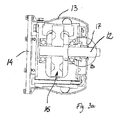
グループで使用されるように設計されたピッキングバンク10の例が、図2および3に示されている。このピッキングバンクは、カバー部材13の開口部から突出する軸12を回転させるための独自のモータ11を有し、見やすくするためピッキングヘッドは取り外されている。軸12を回転させるのに使用される駆動機構を包囲する中空の管形ハウジングを一緒に形成するように、カバー部材13は支持板14に装着されている。ピッキングバンクの端部は端板15により密閉され、ハウジングの上下側面は、隣接のピッキングバンクが近接並置状態で配設されながら相互位置および角度の調節を可能とするように、ともに湾曲している。
An example of a picking
この実施形態において、駆動機構16は相互に嵌合する一連の歯車であり、その一つがモータ11により駆動されるが、駆動機構が広く使用されているチェーン駆動のベルトタイプのものであるか、いくつかの小型モータが各ピッキングバンクと連動するようなピッキングバンクにも適用されることが理解されるべきである。
In this embodiment, the
図2の右側に見られる端板15は3個の開口部151,152,153を備え、そのうち中央の開口部152は、食鳥脱毛装置にピッキングバンクを取り付ける時の使用が想定され、装置のピンまたは同様の突出部が開口部へ簡単に挿入される。他の開口部の一方、この事例では最上部の開口部151は、端板15の上側を押すか引くことで中央開口部152を中心としてピッキングバンクを回転させてその動作角度を変化させうる、油圧シリンダなどの位置調節デバイスの装着に使用される。最後の開口部、この事例では最下部の開口部153は、ピッキングバンクの内側へのアクセスを提供してガスまたは空気のための流入口として機能する。
The end plate 15 seen on the right side of FIG. 2 comprises three
以下では、単純性のため、異なる意図が明記されないかぎり、すべてのガス、空気、および混合物についての共通名称として、「ガス」の語が使用されるだろう。 In the following, for simplicity, the term “gas” will be used as a common name for all gases, air, and mixtures unless a different intention is specified.
図3aに見られるように、駆動機構16は、カバー部材13と支持板14とにより画定されるスペースの大部分を占めるが、それにもかかわらず、ガスが長さ方向に通過することが可能である。それからガスは、流入開口部を包含する端板15と反対にある端板15の開口部(不図示)を介して抜き出されるが、図2および3bに矢印Gで図示されているように軸12と軸ベアリング17との間の開口部を介してガスが漏出可能である。やはりベアリングが軸を支持しなければならないので、これらの軸開口部は通常は0.5mm未満の幅を有するが、最適なサイズは、使用される軸、ベアリング、およびピッキングヘッドのタイプに、また処理される鳥の種類に応じたものであり、そのため実験によって判断されなければならない。同様に、ガス流の制御および最適化を行うため、ベアリングおよび/または軸は、長手方向の水路のような輪郭を備えうる。図3bでガスまたは空気の辿る経路から分かるように、開口部がラビリンスを形成することにも注意すべきである。これは、ピッキングバンクの外側の清掃中には特に、夾雑物および水の侵入を防止するのに役立つ。
As seen in FIG. 3a, the
軸開口部を介して流出するガスまたは空気が多いほど、こうしてピッキングバンクへ侵入する羽毛、夾雑物、および水が少なくなるが、すべてのガスまたは空気が軸開口部を介して流出する場合には流入部から最も遠い軸開口部で充分な流れを達成するのは困難となりうる。そのため、一方の端板15の流入開口部153から反対の端板の流出部までの一次流をピッキングバンクの中に設けること、および/またはピッキングバンクの長さにわたっていくつかの流入口を分散させることが有利であろう。ガスの分散に関する問題の程度は当然、ピッキングバンクの設計、とりわけその長さに依存し、これに従って流入口等の設置が設計されなければならないだろう。 The more gas or air that flows out through the shaft opening, the less feathers, contaminants, and water will enter the picking bank, but if all gas or air flows out through the shaft opening, Achieving sufficient flow at the axial opening furthest from the inflow can be difficult. Therefore, a primary flow from the inflow opening 153 of one end plate 15 to the outflow portion of the opposite end plate is provided in the picking bank and / or several inlets are distributed over the length of the picking bank. It would be advantageous. The extent of the problem with gas distribution naturally depends on the design of the picking bank, especially its length, and the installation of inlets etc. will have to be designed accordingly.
水の進入に対して、またピッキングバンク10への羽毛および夾雑物の侵入に対して可能な限り最良な保護を達成するため、内側に一定の過圧が保持される。しかし、圧力の自然な変動によって結果的に時々は過圧が失われるようにし、そして不要物を吹き飛ばすことのできる過圧の再確立に頼ることも可能である。同様に、短時間での規則的な圧力の上昇を、おそらくは液体と気体のいずれかの洗浄剤の導入との組合せで、洗浄目的に使用してもよい。
In order to achieve the best possible protection against water ingress and against feather and dirt ingress into the picking
図2,3a,3bの実施形態において、ピッキングバンクは、それ自体が流路を形成する中空の密閉構成のものであるが、本発明は、より開放的な構成のピッキングバンクにも関する。一例として、ピッキングバンクが支持板14なしで製作されうる、および/またはカバー部材13が平面でありうる。このような事例では、例えば図2の矢印Gと実質上平行な方向にガスがピッキング列の裏側へ吹き付けられ、軸開口部へ侵入しないあらゆるガスは単純に残留してピッキングバンクの側面および端部を介して漏出しうる。しかし、ガスは図2のように端部からも注入され、その際には、ガスの流れを所望の方向に誘導するように機能する一つ以上のフィン状バッフルまたは偏向器をピッキングバンクが備えうる。
In the embodiment of FIGS. 2, 3a and 3b, the picking bank is of a hollow sealed configuration which itself forms a flow path, but the invention also relates to a more open configuration of the picking bank. As an example, the picking bank can be made without the
当業者には理解されるように、ガスの流れパターンは、これがピッキングバンクと出会う際の方向および速度に強く依存し、そのためこれらの要因は所与の設計のピッキングバンクについて所望の流れパターンを達成するように調節されうる。しかし、ガスは少なくとも10m/秒、しかし25m/秒を超えずに移動することが好ましい。所望のガス速度を達成するには送風器が使用されうるが、食鳥脱毛装置に関連して設けられる圧縮器により、または圧力タンクに蓄積されたガスを使用することにより、ガスを圧縮することも可能である。 As will be appreciated by those skilled in the art, the gas flow pattern is highly dependent on the direction and speed in which it encounters the picking bank, so these factors achieve the desired flow pattern for a given design of picking bank. Can be adjusted to However, it is preferred that the gas move at least 10 m / sec, but not exceeding 25 m / sec. A blower can be used to achieve the desired gas velocity, but compressing the gas by means of a compressor provided in connection with the poultry hair removal apparatus or by using gas stored in a pressure tank Is also possible.
図2,3a,3bに示されたタイプのピッキングバンクでは、低温保管ルームからの低温空気を使用することと、流入開口部153を介してこれを300l/分で注入してピッキングバンクの内側に200〜250ミリバールの過圧を発生させると好都合であることが判明している。しかし、軸の数、各軸の開口部のサイズ、およびピッキングバンクの全体的気密度に応じて、過圧を維持するのにより多くの空気またはガスを使用する必要がありうる。他の事例では、より低い圧力で作動することも容認可能であるが、大気圧を上回る150ミリバール以上の圧力を常に維持することが好ましい。 The picking bank of the type shown in FIGS. 2, 3a and 3b uses cold air from a cold storage room and injects it at 300 l / min through the inflow opening 153 to the inside of the picking bank. It has proved advantageous to generate an overpressure of 200 to 250 mbar. However, depending on the number of shafts, the size of the openings in each shaft, and the overall air density of the picking bank, it may be necessary to use more air or gas to maintain the overpressure. In other cases, it may be acceptable to operate at a lower pressure, but it is preferable to always maintain a pressure of 150 mbar above atmospheric pressure.
ガスは原則として、オゾンまたは二酸化炭素のように食品産業での使用が承認されているいかなるガスでもよいが、入手可能性および価格ゆえに、大気の使用が好都合であることが多い。この事例では、ガス供給源は単純に、大気をピッキングバンクへ誘導する送風器でありうるが、熱湯処理プロセスでの水の使用ゆえに、食鳥脱毛装置の外側であっても大気が比較的高湿度であることが多いだろう。羽毛、夾雑物、および水分を吹き飛ばすガスの能力、および/または進入を防止する過圧のみに頼る場合には、これは問題ではないだろうが、ガスが低い相対湿度を有することが好ましい。これは、乾燥器エリアからの空気を使用することにより、または空気を加熱して相対湿度を低下させることにより、簡単に達成されうる。一例として、摂氏20度の温度の大気から始めてこれを摂氏60度まで加熱する場合には、相対湿度は100%から13%まで低下するが、別の言い方をすると、最初の含水量の7倍以上も加湿できることになるだろう。ガスの加熱は、細菌の少なくとも一部が死滅するというさらなる利点も有し、摂氏84度以上までガスを加熱した場合には、抗菌性洗浄剤の使用の必要が回避されることが多い。しかし、このような高温で装置を運転すると、使用される材料の劣化を起こすため、短い間隔のみで、または装置が運転されていない時の清掃作業の一部として、高温ガスを印加することが好ましい。 The gas can in principle be any gas approved for use in the food industry, such as ozone or carbon dioxide, but due to availability and price, use of the atmosphere is often convenient. In this case, the gas source can simply be a blower that directs the atmosphere to the picking bank, but due to the use of water in the hot water treatment process, the atmosphere is relatively high even outside the poultry hair removal apparatus. It will often be humidity. This may not be a problem when relying solely on the ability of the gas to blow off feathers, contaminants, and moisture, and / or overpressure to prevent ingress, but it is preferred that the gas have a low relative humidity. This can be easily achieved by using air from the dryer area or by heating the air to reduce the relative humidity. As an example, if you start from an atmosphere with a temperature of 20 degrees Celsius and heat it to 60 degrees Celsius, the relative humidity will drop from 100% to 13%, but in other words, 7 times the initial water content The above will be able to humidify. Gas heating also has the added benefit of killing at least some of the bacteria, and the need for the use of antimicrobial detergents is often avoided when the gas is heated to 84 degrees Celsius or higher. However, operating the device at such high temperatures will cause degradation of the materials used, so hot gas may be applied only at short intervals or as part of a cleaning operation when the device is not operating. preferable.
他のタイプのガスはタンクで納入されるか、オゾン発生器のような適当な設備で発生されなければならず、このようなガスはいくつかの事例ではやはり加熱されることが理解されるべきである。 It should be understood that other types of gas must be delivered in tanks or generated in appropriate equipment such as an ozone generator, and such gases are still heated in some cases. It is.
ガスをピッキングバンクへ出入させるための適当な設備の用意は、使用されるガスのタイプと、システムで使用される圧縮器、タンク、送風器、加熱器等のタイプおよび位置に依存するが、共通のチューブ類およびパイプシステムに基づくことが可能なので、これは当業者にとって何の問題も含まないだろう。 Appropriate equipment for gas to and from the picking bank depends on the type of gas used and the type and location of the compressors, tanks, blowers, heaters, etc. used in the system. This would not involve any problems for the person skilled in the art since it can be based on a variety of tubes and pipe systems.
上述したことを別にすると、材料の選択を含めてピッキングバンクの他の詳細は先行技術のままでありうる。 Apart from the above, other details of the picking bank, including material selection, may remain prior art.
1 食鳥脱毛装置
2 鳥
3 シャックル
4 頭上コンベヤ
5 フレーム
6 脱毛アセンブリ
7 支持体
8 ピッキングヘッド
10 ピッキングバンク
11 モータ
12 軸
13 カバー部材
14 支持板
15 端板
16 駆動機構
17 軸ベアリング
151,152,153 開口部
DESCRIPTION OF
Claims (15)
ガスまたは空気が前記カバー部材の前記内側の流入経路に沿って前方へ前記駆動機構まで流され、前記食鳥脱毛装置が作動している時に前記ガスまたは空気が前記ピッキングヘッドを囲繞する空気よりも低い相対湿度を有する、ことを特徴とする方法。 An operation method of a phagocytic hair removal apparatus in which a drive mechanism is used to rotate a plurality of picking heads of a picking bank, wherein each of the picking heads protrudes from an opening of a cover member and is supported by a bearing Is attached to the outside of the cover member, and the driving mechanism is disposed inside the cover member opposite to the picking head,
Gas or air is flowed forward to the drive mechanism along the inner inflow path of the cover member, and the gas or air is more than the air surrounding the picking head when the phagocytic hair removal device is operating. A method characterized by having a low relative humidity.
前記カバー部材の前記内側の流入経路に沿って前記駆動機構へガスまたは空気を誘導するのに適した一つ以上の導流体をさらに包含し、前記一つ以上の導流体へガスまたは空気を案内するのに適した吸入口が前記ピッキングヘッドから離れる方向を向いている、ことを特徴とするピッキングバンク。 Including at least one cover member, a plurality of picking heads, and a driving mechanism for rotating the picking head, wherein each of the picking heads has an axis protruding from an opening of the cover member. A picking bank for use in a phagocytic hair removal device, wherein the shaft is supported by a bearing, and the drive mechanism is disposed inside the cover member opposite to the picking head. ,
And further including one or more fluids suitable for directing gas or air to the drive mechanism along the inner inflow path of the cover member to guide the gas or air to the one or more fluids. A picking bank, characterized in that a suction port suitable for performing is directed away from the picking head.
Applications Claiming Priority (1)
| Application Number | Priority Date | Filing Date | Title |
|---|---|---|---|
| PCT/DK2012/050095 WO2013143539A1 (en) | 2012-03-28 | 2012-03-28 | A method for operating a poultry defeathering apparatus and a picking bank for use in a poultry defeathering apparatus |
Publications (2)
| Publication Number | Publication Date |
|---|---|
| JP2015514399A JP2015514399A (en) | 2015-05-21 |
| JP5867887B2 true JP5867887B2 (en) | 2016-02-24 |
Family
ID=45952398
Family Applications (1)
| Application Number | Title | Priority Date | Filing Date |
|---|---|---|---|
| JP2015502097A Active JP5867887B2 (en) | 2012-03-28 | 2012-03-28 | Method of operating a phagocytic hair removal device and picking bank for use in phagocytic hair removal device |
Country Status (11)
| Country | Link |
|---|---|
| US (1) | US9107427B2 (en) |
| EP (1) | EP2830426B1 (en) |
| JP (1) | JP5867887B2 (en) |
| KR (1) | KR101921705B1 (en) |
| CN (1) | CN104486951B (en) |
| BR (1) | BR112014024114B8 (en) |
| CA (1) | CA2872013C (en) |
| ES (1) | ES2582641T3 (en) |
| PL (1) | PL2830426T3 (en) |
| RU (1) | RU2585855C2 (en) |
| WO (1) | WO2013143539A1 (en) |
Families Citing this family (3)
| Publication number | Priority date | Publication date | Assignee | Title |
|---|---|---|---|---|
| US9809387B2 (en) * | 2016-03-14 | 2017-11-07 | Chuan Yang Foods Machine Co., Ltd. | Anti-sticking conveyor belt and conveyor strips of frying machine |
| CN113924999B (en) * | 2021-11-03 | 2023-03-24 | 广西壮族自治区畜牧研究所 | A plucker for collecting ostrich feather |
| KR102401129B1 (en) * | 2022-02-22 | 2022-05-20 | 편진호 | Shackle cleaning device for slaughter |
Family Cites Families (20)
| Publication number | Priority date | Publication date | Assignee | Title |
|---|---|---|---|---|
| US3561040A (en) * | 1968-08-02 | 1971-02-09 | Food Equipment Inc | Spraying apparatus and method for use in conjunction with fowl defeathering apparatus |
| NL6814207A (en) | 1968-10-04 | 1970-04-07 | ||
| NL155175B (en) | 1968-10-24 | 1977-12-15 | Stork Amsterdam | FARM FOR PICKING POULTRY. |
| US3665539A (en) * | 1970-04-09 | 1972-05-30 | Food Equipment Inc | Automatic shackle washer |
| US3716892A (en) * | 1970-10-19 | 1973-02-20 | Int Agri Systems | Method and apparatus for processing poultry |
| US3797068A (en) * | 1972-04-06 | 1974-03-19 | Food Equipment Inc | Fowl agitating and wetting system |
| CA1002712A (en) * | 1973-01-25 | 1977-01-04 | Johannes J. Smorenburg | Poultry processing equipment |
| US4175302A (en) * | 1978-07-28 | 1979-11-27 | Simon-Johnson, Inc. | Sealed feather picking unit |
| US4199842A (en) * | 1978-11-08 | 1980-04-29 | Bergeron Camille F | Feather removing apparatus and method |
| US4514879A (en) | 1983-01-26 | 1985-05-07 | Hazenbroek Jacobus E | Suspended feather picker with rotatable sections |
| US4868950A (en) * | 1989-01-03 | 1989-09-26 | Centennial Machine Company, Inc. | Fowl scalding apparatus and method |
| DE69404479T2 (en) * | 1993-11-26 | 1997-12-04 | British Tech Group | Apparatus for plucking poultry |
| JP2001254837A (en) * | 2000-03-08 | 2001-09-21 | Shimadaya Corp | Shaft sealing structure for container fixing type mixer to be used for food processing |
| DE10148568A1 (en) * | 2001-10-01 | 2003-04-24 | Bernhard Wichelmann | Method and device for preparing slaughtered poultry for plucking |
| US7175516B2 (en) | 2002-01-18 | 2007-02-13 | Memco | Poultry processing hub and belt assembly |
| US20040147211A1 (en) | 2003-01-24 | 2004-07-29 | Mostoller Charles R. | Poultry defeathering process and apparatus |
| US6918825B2 (en) * | 2003-08-26 | 2005-07-19 | Everett T. Conaway | Poultry de-feathering apparatus and method |
| CN2855088Y (en) * | 2005-12-20 | 2007-01-10 | 翁楚隆 | Domestic fowl depilator |
| ATE521241T1 (en) | 2005-12-21 | 2011-09-15 | Linco Food Systems As | POULTRY PULLER |
| CN101946819A (en) * | 2010-08-19 | 2011-01-19 | 陈志中 | Poultry feather plucker |
-
2012
- 2012-03-28 PL PL12713582.0T patent/PL2830426T3/en unknown
- 2012-03-28 JP JP2015502097A patent/JP5867887B2/en active Active
- 2012-03-28 EP EP12713582.0A patent/EP2830426B1/en active Active
- 2012-03-28 CN CN201280073485.6A patent/CN104486951B/en active Active
- 2012-03-28 WO PCT/DK2012/050095 patent/WO2013143539A1/en active Application Filing
- 2012-03-28 US US14/388,547 patent/US9107427B2/en active Active
- 2012-03-28 RU RU2014141003/13A patent/RU2585855C2/en active
- 2012-03-28 BR BR112014024114A patent/BR112014024114B8/en active IP Right Grant
- 2012-03-28 ES ES12713582.0T patent/ES2582641T3/en active Active
- 2012-03-28 CA CA2872013A patent/CA2872013C/en active Active
- 2012-03-28 KR KR1020147029442A patent/KR101921705B1/en active IP Right Grant
Also Published As
| Publication number | Publication date |
|---|---|
| CA2872013A1 (en) | 2013-10-03 |
| US9107427B2 (en) | 2015-08-18 |
| BR112014024114B8 (en) | 2023-02-14 |
| EP2830426B1 (en) | 2016-04-20 |
| US20150133040A1 (en) | 2015-05-14 |
| CN104486951B (en) | 2016-11-09 |
| ES2582641T3 (en) | 2016-09-14 |
| CN104486951A (en) | 2015-04-01 |
| RU2585855C2 (en) | 2016-06-10 |
| BR112014024114A2 (en) | 2017-06-20 |
| CA2872013C (en) | 2016-10-11 |
| KR20140147848A (en) | 2014-12-30 |
| JP2015514399A (en) | 2015-05-21 |
| PL2830426T3 (en) | 2016-11-30 |
| WO2013143539A1 (en) | 2013-10-03 |
| BR112014024114B1 (en) | 2019-11-05 |
| KR101921705B1 (en) | 2018-11-26 |
| EP2830426A1 (en) | 2015-02-04 |
| RU2014141003A (en) | 2016-05-20 |
Similar Documents
| Publication | Publication Date | Title |
|---|---|---|
| JP5867887B2 (en) | Method of operating a phagocytic hair removal device and picking bank for use in phagocytic hair removal device | |
| CA2203429C (en) | Method and apparatus for steam pasteurization of meat | |
| ES2700655T3 (en) | Tempering system with process fluid purification | |
| CN103668840A (en) | Hot wind spray nozzle of tenter and hot wind spray apparatus of tenter using the same | |
| JP2009544312A (en) | Poultry heat treatment apparatus and poultry heat treatment method | |
| KR20110029502A (en) | Fruit cleaning device with hot water | |
| BR112017012194B1 (en) | Apparatus and method for loading product into containers | |
| ES2339785T3 (en) | METHOD AND SYSTEM FOR SCALDING DEAD CORRAL BIRDS. | |
| CN108452363A (en) | A kind of efficient ultraviolet air sterilization chlorination equipment | |
| US9210949B2 (en) | Method and means for extending the shelf life of food products | |
| TW201429404A (en) | Poultry carcass cooling and conveying device | |
| JP4724189B2 (en) | Longitudinal crop cleaning equipment | |
| KR20080050479A (en) | Device for treating elongate food products with a conditioned airflow | |
| US20220134393A1 (en) | Methods and Systems for Automated Cleaning of Immersion Tanks | |
| KR20220110256A (en) | Cleaning an article to be cleaned having at least one cavity in a conveyor washer | |
| JP5938027B2 (en) | Steam cleaning device | |
| CN110327696A (en) | A kind of train air-conditioning strainer cross drive cleaning equipment | |
| JP5064422B2 (en) | Manufacturing apparatus and manufacturing method for processed fishery products | |
| US20080241325A1 (en) | Device and Method for Removing Liquid From a Food Strand | |
| KR102077045B1 (en) | Sterilizng package and sterilizer thereof | |
| KR20170060344A (en) | Cleaning and drying equipment for fishing net | |
| JP2008517597A5 (en) | ||
| US20220387646A1 (en) | Dual zone systems and methods for disinfecting with ozone | |
| CN211204810U (en) | Drying and sterilizing device for manufacturing cosmetic packaging bottles | |
| KR101808727B1 (en) | Surface treatment device |
Legal Events
| Date | Code | Title | Description |
|---|---|---|---|
| A977 | Report on retrieval |
Free format text: JAPANESE INTERMEDIATE CODE: A971007 Effective date: 20151203 |
|
| TRDD | Decision of grant or rejection written | ||
| A01 | Written decision to grant a patent or to grant a registration (utility model) |
Free format text: JAPANESE INTERMEDIATE CODE: A01 Effective date: 20151208 |
|
| A61 | First payment of annual fees (during grant procedure) |
Free format text: JAPANESE INTERMEDIATE CODE: A61 Effective date: 20151225 |
|
| R150 | Certificate of patent or registration of utility model |
Ref document number: 5867887 Country of ref document: JP Free format text: JAPANESE INTERMEDIATE CODE: R150 |
|
| R250 | Receipt of annual fees |
Free format text: JAPANESE INTERMEDIATE CODE: R250 |
|
| R250 | Receipt of annual fees |
Free format text: JAPANESE INTERMEDIATE CODE: R250 |
|
| R250 | Receipt of annual fees |
Free format text: JAPANESE INTERMEDIATE CODE: R250 |
|
| R250 | Receipt of annual fees |
Free format text: JAPANESE INTERMEDIATE CODE: R250 |
|
| S531 | Written request for registration of change of domicile |
Free format text: JAPANESE INTERMEDIATE CODE: R313531 |
|
| S533 | Written request for registration of change of name |
Free format text: JAPANESE INTERMEDIATE CODE: R313533 |
|
| R350 | Written notification of registration of transfer |
Free format text: JAPANESE INTERMEDIATE CODE: R350 |
|
| R250 | Receipt of annual fees |
Free format text: JAPANESE INTERMEDIATE CODE: R250 |
|
| R250 | Receipt of annual fees |
Free format text: JAPANESE INTERMEDIATE CODE: R250 |