JP5866282B2 - Compression after beam shaping in ultrasonic systems - Google Patents
Compression after beam shaping in ultrasonic systems Download PDFInfo
- Publication number
- JP5866282B2 JP5866282B2 JP2012518545A JP2012518545A JP5866282B2 JP 5866282 B2 JP5866282 B2 JP 5866282B2 JP 2012518545 A JP2012518545 A JP 2012518545A JP 2012518545 A JP2012518545 A JP 2012518545A JP 5866282 B2 JP5866282 B2 JP 5866282B2
- Authority
- JP
- Japan
- Prior art keywords
- samples
- compressed
- group
- sample
- compression
- Prior art date
- Legal status (The legal status is an assumption and is not a legal conclusion. Google has not performed a legal analysis and makes no representation as to the accuracy of the status listed.)
- Expired - Fee Related
Links
Images


Classifications
-
- G—PHYSICS
- G01—MEASURING; TESTING
- G01S—RADIO DIRECTION-FINDING; RADIO NAVIGATION; DETERMINING DISTANCE OR VELOCITY BY USE OF RADIO WAVES; LOCATING OR PRESENCE-DETECTING BY USE OF THE REFLECTION OR RERADIATION OF RADIO WAVES; ANALOGOUS ARRANGEMENTS USING OTHER WAVES
- G01S7/00—Details of systems according to groups G01S13/00, G01S15/00, G01S17/00
- G01S7/52—Details of systems according to groups G01S13/00, G01S15/00, G01S17/00 of systems according to group G01S15/00
- G01S7/52017—Details of systems according to groups G01S13/00, G01S15/00, G01S17/00 of systems according to group G01S15/00 particularly adapted to short-range imaging
- G01S7/52023—Details of receivers
- G01S7/52034—Data rate converters
-
- A—HUMAN NECESSITIES
- A61—MEDICAL OR VETERINARY SCIENCE; HYGIENE
- A61B—DIAGNOSIS; SURGERY; IDENTIFICATION
- A61B8/00—Diagnosis using ultrasonic, sonic or infrasonic waves
- A61B8/06—Measuring blood flow
-
- A—HUMAN NECESSITIES
- A61—MEDICAL OR VETERINARY SCIENCE; HYGIENE
- A61B—DIAGNOSIS; SURGERY; IDENTIFICATION
- A61B8/00—Diagnosis using ultrasonic, sonic or infrasonic waves
- A61B8/13—Tomography
-
- A—HUMAN NECESSITIES
- A61—MEDICAL OR VETERINARY SCIENCE; HYGIENE
- A61B—DIAGNOSIS; SURGERY; IDENTIFICATION
- A61B8/00—Diagnosis using ultrasonic, sonic or infrasonic waves
- A61B8/48—Diagnostic techniques
- A61B8/488—Diagnostic techniques involving Doppler signals
-
- A—HUMAN NECESSITIES
- A61—MEDICAL OR VETERINARY SCIENCE; HYGIENE
- A61B—DIAGNOSIS; SURGERY; IDENTIFICATION
- A61B8/00—Diagnosis using ultrasonic, sonic or infrasonic waves
- A61B8/54—Control of the diagnostic device
-
- G—PHYSICS
- G01—MEASURING; TESTING
- G01S—RADIO DIRECTION-FINDING; RADIO NAVIGATION; DETERMINING DISTANCE OR VELOCITY BY USE OF RADIO WAVES; LOCATING OR PRESENCE-DETECTING BY USE OF THE REFLECTION OR RERADIATION OF RADIO WAVES; ANALOGOUS ARRANGEMENTS USING OTHER WAVES
- G01S7/00—Details of systems according to groups G01S13/00, G01S15/00, G01S17/00
- G01S7/52—Details of systems according to groups G01S13/00, G01S15/00, G01S17/00 of systems according to group G01S15/00
- G01S7/52017—Details of systems according to groups G01S13/00, G01S15/00, G01S17/00 of systems according to group G01S15/00 particularly adapted to short-range imaging
- G01S7/52023—Details of receivers
-
- G—PHYSICS
- G10—MUSICAL INSTRUMENTS; ACOUSTICS
- G10K—SOUND-PRODUCING DEVICES; METHODS OR DEVICES FOR PROTECTING AGAINST, OR FOR DAMPING, NOISE OR OTHER ACOUSTIC WAVES IN GENERAL; ACOUSTICS NOT OTHERWISE PROVIDED FOR
- G10K11/00—Methods or devices for transmitting, conducting or directing sound in general; Methods or devices for protecting against, or for damping, noise or other acoustic waves in general
- G10K11/18—Methods or devices for transmitting, conducting or directing sound
- G10K11/26—Sound-focusing or directing, e.g. scanning
- G10K11/34—Sound-focusing or directing, e.g. scanning using electrical steering of transducer arrays, e.g. beam steering
- G10K11/341—Circuits therefor
- G10K11/346—Circuits therefor using phase variation
-
- H—ELECTRICITY
- H03—ELECTRONIC CIRCUITRY
- H03M—CODING; DECODING; CODE CONVERSION IN GENERAL
- H03M7/00—Conversion of a code where information is represented by a given sequence or number of digits to a code where the same, similar or subset of information is represented by a different sequence or number of digits
- H03M7/30—Compression; Expansion; Suppression of unnecessary data, e.g. redundancy reduction
- H03M7/40—Conversion to or from variable length codes, e.g. Shannon-Fano code, Huffman code, Morse code
Description
本発明は、受信した超音波信号サンプルに適用される受信ビーム成形器によって超音波画像形成システムに発生されるビーム成形サンプルを圧縮することに係り、より特定すれば、各ビームのビーム成形サンプルを独立して圧縮しそして画像形成のための処理の前に解凍することに係る。 The present invention relates to compressing a beamformed sample generated in an ultrasound imaging system by a receive beamformer applied to a received ultrasound signal sample, and more particularly, to form a beamformed sample for each beam. Independent compression and decompression prior to processing for image formation.
医療用超音波システムは、臨床医により対象者に置かれたトランスジューサから超音波ビームを送信することにより対象者の体内解剖学的組織をスキャンする。超音波は、異なる音響インピーダンスを有する体内組織の界面で反射されて、エコーを発生する。トランスジューサは、エコーを受信して、電気的な超音波信号へ変換する。超音波システムは、超音波信号に一連の処理ステップを適用して、画像又は一連の画像を発生し、それらは、臨床医による分析のためにコントロールコンソールに表示される。受信したエコーの強度に基づき形成される画像は、Bモード画像と称される。更に、システムは、超音波信号のドップラーシフトを測定して、血液のような流体の流れを指示するカラー画像を発生すると共に、診断に有用な付加的な分析を遂行する。 A medical ultrasound system scans a subject's body anatomy by transmitting an ultrasound beam from a transducer placed on the subject by a clinician. Ultrasound is reflected at the interface of body tissues having different acoustic impedances to generate echoes. The transducer receives the echo and converts it into an electrical ultrasonic signal. The ultrasound system applies a series of processing steps to the ultrasound signal to generate an image or series of images that are displayed on a control console for analysis by a clinician. An image formed based on the received echo intensity is referred to as a B-mode image. In addition, the system measures the Doppler shift of the ultrasound signal to generate a color image that indicates the flow of a fluid, such as blood, and performs additional analysis useful for diagnosis.
従来の医療用超音波トランスジューサは、電気信号で駆動されたとき超音波を送信し、返送されるエコーを受信し、そしてその受信エコーを複数のアナログ信号へ変換する圧電素子のアレイを備えている。複数のアナログ/デジタルコンバータ(ADC)がアナログ信号をサンプリングし、その各々がデジタル信号サンプルのストリームを発生する。信号サンプルの典型的なデジタル信号処理は、ビーム成形、ダウン変換、Bモード(輝度)処理及び/又はドップラー処理、スキャン変換、及び表示のための画像処理を含む。ビーム成形器は、信号サンプルのストリームに遅延及び加算オペレーションを適用して、視野内の特定方向に対応するビーム成形サンプルのアレイを形成する。ビーム成形器は、信号サンプルのストリームに異なる遅延パターンを適用することによって視野内の異なる方向に対応するビーム成形サンプルの多数のアレイを発生することができる。次いで、望ましい診断情報のタイプに基づいて、ビーム成形サンプルに対してBモード処理及び/又はドップラー処理を遂行して、Bモード検出サンプル及び/又はドップラー検出サンプルを形成する。検出サンプルの空間的座標は、ビーム成形サンプルのビーム幾何学形状に依然対応する。スキャンコンバータが検出サンプルの座標変換を行って、表示に適したラスタフォーマットを有するデータのフレームを発生する。サンプルのフレームに付加的な画像処理を適用して、二次元(2D)又は三次元(3D)画像として表示できるようにする。 Conventional medical ultrasonic transducers include an array of piezoelectric elements that transmit ultrasonic waves when driven by electrical signals, receive the returned echoes, and convert the received echoes into a plurality of analog signals. . A plurality of analog / digital converters (ADC) sample the analog signal, each of which generates a stream of digital signal samples. Typical digital signal processing of signal samples includes beam shaping, down conversion, B-mode (brightness) processing and / or Doppler processing, scan conversion, and image processing for display. The beam shaper applies a delay and sum operation to the stream of signal samples to form an array of beam shaped samples corresponding to a particular direction in the field of view. The beam shaper can generate multiple arrays of beam-shaped samples corresponding to different directions in the field of view by applying different delay patterns to the stream of signal samples. A B-mode process and / or a Doppler process is then performed on the beam-shaped sample based on the type of diagnostic information desired to form a B-mode detection sample and / or a Doppler detection sample. The spatial coordinates of the detected sample still correspond to the beam geometry of the beam-shaped sample. A scan converter performs coordinate conversion of the detected samples to generate a frame of data having a raster format suitable for display. Additional image processing is applied to the sample frame so that it can be displayed as a two-dimensional (2D) or three-dimensional (3D) image.
医療用超音波システムを改善するための現在の努力は、コンソール/カートシステムの診断能力を高めると共に、画質の改善された小型のポータブル装置を開発することに向けられる。ハイエンドのコンソール又はカートシステムについては、トランスジューサ素子の数を増加して、診断能力を拡張するための高い解像度及び/又は3D画像を発生することが望まれる。トランスジューサ素子の数を増加すると、トランスジューサヘッドからコンソールプロセッサへ通信されるデータの量が増加し、より広い帯域巾の通信チャンネル及びより大きなケーブル接続を要求する。トランスジューサヘッドのデータ取得能力は、操作及びフォームファクタの要件により制約を受ける。手持ち及びハンドヘルド型の超音波装置は、経済的なものであり、小規模な医院、移動処置ユニット及び家庭で使用するのに望ましいものである。これらの装置では、バッテリ寿命も制約となる。超音波システムにおいて超音波信号データをより効率的に処理し、転送し、記憶することで、電力、データ転送帯域巾及びメモリ容量を節約することができる。 Current efforts to improve medical ultrasound systems are aimed at enhancing the diagnostic capabilities of console / cart systems and developing small portable devices with improved image quality. For high-end console or cart systems, it is desirable to increase the number of transducer elements to generate high resolution and / or 3D images to extend diagnostic capabilities. Increasing the number of transducer elements increases the amount of data communicated from the transducer head to the console processor, requiring a wider bandwidth communication channel and larger cabling. The data acquisition capability of the transducer head is constrained by operational and form factor requirements. Handheld and handheld ultrasound devices are economical and desirable for use in small clinics, mobile treatment units and homes. In these devices, battery life is also a limitation. By more efficiently processing, transferring and storing ultrasound signal data in an ultrasound system, power, data transfer bandwidth and memory capacity can be saved.
超音波信号データの圧縮は、コンソール/カートシステム及びポータブルシステムの両方に利益をもたらすことができる。その利益とは、システムのデータ送信帯域巾、メモリ容量、及び電力要件を下げることを含む。ポータブル又は手持ち式超音波システムでは、この利益で、重量が減少され、バッテリ寿命が延びる。コンソールシステムの場合には、圧縮は、トランスジューサヘッドにより取得されるデータ量の増加及び超音波信号プロセッサへのデータの転送の影響を軽減する。計算効率のよい圧縮は、システムの複雑さへの影響がほとんど又は全くないという圧縮の利益をもたらす。 The compression of ultrasound signal data can benefit both console / cart systems and portable systems. The benefits include lowering the data transmission bandwidth, memory capacity, and power requirements of the system. In portable or handheld ultrasound systems, this benefit reduces weight and extends battery life. In the case of a console system, compression mitigates the effects of increasing the amount of data acquired by the transducer head and transferring the data to the ultrasonic signal processor. Computational compression provides the benefit of compression with little or no impact on system complexity.
ここで使用する「圧縮」という語は、信号サンプルを表すビットの数が減少されそして信号サンプルがその後に表示のための処理の前に解凍されるという超音波信号サンプルのデータ圧縮を指す。超音波画像形成システムのある説明では、データ圧縮ではなく「パルス圧縮」を意味するように圧縮という語が使用される。パルス圧縮は、送信された超音波パルスのフィルタリング及び/又は変調と、受信した超音波パルスの逆フィルタリング及び/又は復調とを指す。(例えば、2004年、Ultrasonics、第42巻、第1101−1109ページに掲載されたV.Behar及びD.Adam著の“Parameter optimization of pulse compression in ultrasound imaging system with coded excitation”を参照されたい。)超音波画像形成システムのある説明では、データ圧縮ではなく「対数圧縮」を意味するように圧縮という語が使用される。この点について、対数圧縮は、処理された超音波データの対数、典型的に、表示の前の大きさ検出データを計算することを指す。(例えば、2008年11月、Texas Instruments SPRAB 12、第1−26ページに掲載されたA.Murtaza氏等の“Signal Processing Overview of Ultrasound Systems for Medical Imaging”を参照されたい。)パルス圧縮及び対数圧縮は、両方とも、時間ドメイン及び周波数ドメインにおいて送信又は受信超音波信号の特性を意図的に変更する。受信超音波信号サンプルのデータ圧縮に続いて解凍を行うことは、時間及び周波数ドメインにおいて信号特性を保存するプロセスである。ここでの説明は、超音波信号サンプルのロスレス及びロッシー圧縮を参照する。ロスレス圧縮では、解凍サンプルがオリジナルサンプルと同一の値を有する。ロッシー圧縮では、解凍サンプルがオリジナルサンプルと同様であるが、同一ではない。ここでの説明は、生、又は処理済みの、即ち表示のための超音波画像を形成するよう最終的に処理された、超音波データのアレイを指すために「フレーム」という語を使用する。又、従来の超音波画像形成システムの説明は、超音波データのフレームを指すために「スクリーン」という語を使用している。ここでの説明では、「リアルタイム」とは、デジタル信号のサンプルレートと少なくとも同程度に速いレートを意味する。「リアルタイム」という語は、デジタル信号の処理、転送及び記憶のためのレートを記述するのに使用することができる。サンプルレートとは、ADCがアナログ信号の変換中にデジタル信号のサンプルを形成するレートである。従来の超音波画像形成システムのある説明は、超音波画像を表示するためのフレームレートを指すために「リアルタイム」という語を使用する。ここでの説明は、リアルタイムを、フレームレートの解釈ではなく、サンプルレートに関連付ける。 As used herein, the term “compression” refers to data compression of an ultrasound signal sample in which the number of bits representing the signal sample is reduced and the signal sample is subsequently decompressed prior to processing for display. In some descriptions of ultrasound imaging systems, the term compression is used to mean “pulse compression” rather than data compression. Pulse compression refers to filtering and / or modulation of transmitted ultrasound pulses and inverse filtering and / or demodulation of received ultrasound pulses. (See, for example, “Parameter optimization of pulse compression in ultrasound imaging system with coded excitation” by V. Behar and D. Adam, published in 2004, Ultrasonics, Vol. 42, pages 1101-1109.) In some descriptions of ultrasound imaging systems, the term compression is used to mean “logarithmic compression” rather than data compression. In this regard, logarithmic compression refers to calculating the logarithm of processed ultrasound data, typically magnitude detection data prior to display. (See, eg, “Signal Processing Overview of Ultrasound Systems for Medical Imaging” by A. Murtaza et al., November 2008, Texas Instruments SPRAB 12, page 1-26.) Pulse Compression and Logarithmic Compression Both intentionally alter the characteristics of transmitted or received ultrasound signals in the time and frequency domains. Performing decompression following data compression of received ultrasound signal samples is a process that preserves signal characteristics in the time and frequency domains. The description here refers to lossless and lossy compression of ultrasound signal samples. In lossless compression, the decompressed sample has the same value as the original sample. In lossy compression, the decompressed sample is similar to the original sample, but not the same. The description herein uses the term “frame” to refer to an array of ultrasound data that is raw or processed, ie, finally processed to form an ultrasound image for display. Also, the description of conventional ultrasound imaging systems uses the term “screen” to refer to a frame of ultrasound data. In this description, “real time” means a rate that is at least as fast as the sample rate of the digital signal. The term “real time” can be used to describe the rate for processing, transferring and storing digital signals. The sample rate is the rate at which the ADC forms samples of the digital signal during conversion of the analog signal. One description of a conventional ultrasound imaging system uses the term “real time” to refer to a frame rate for displaying an ultrasound image. The description here relates real time to sample rate rather than interpretation of frame rate.
超音波システムにおけるデータ圧縮の以前の適用は、画像成形のためのスキャン変換の前後に別のデータ圧縮を含ませている。2001年11月13日に発行された“Ultrasonic Diagnostic Device”と題する米国特許第6,315,722号において、ヤエガシ氏は、ADCユニットから出力される超音波信号サンプルを記憶するための時間軸延長ユニットを述べている。時間軸延長ユニットは、ADCユニットから出力されるレートでデータを書き込み、そしてそれより低いレートでデータを読み出す。時間軸延長ユニットは、1つのスクリーン又はフレームに対して信号サンプルを記憶し、そして先入れ先出し(FIFO)メモリを使用して具現化される。時間軸延長ユニットから読み取られた信号サンプルをデータ圧縮ユニットで圧縮する。ヤエガシ氏は、1つのデータフレーム内の空間的相関を利用するための離散的コサイン変換(DCT)に基づく方法、又は複数のデータフレームのためのMPEG圧縮方法のような画像圧縮技術を適用することを述べている。(MPEGとは、ムービングピクチャーエキスパートグループにより開発されたビデオデータ圧縮規格を指す。)圧縮されたサンプルは、ハードディスクのような大量メモリ装置に記憶される。データ圧縮は、大量メモリ装置に必要とされる記憶容量を減少する。画像の発生については、データ拡張ユニットが、大量メモリ装置から検索される圧縮サンプルを解凍する。フィルタリング、対数変換、検出及びデジタルスキャン変換を含む従来のオペレーションが、画像形成及び表示のために解凍サンプルに適用される。ヤエガシ氏は、処理シーケンスにおけるビーム成形については開示していない。 Previous applications of data compression in ultrasound systems include separate data compression before and after scan conversion for image shaping. In US Pat. No. 6,315,722 entitled “Ultrasonic Diagnostic Device” issued on November 13, 2001, Mr. Yaegashi extended the time axis for storing the ultrasonic signal samples output from the ADC unit. Stated unit. The time axis extension unit writes data at a rate output from the ADC unit, and reads data at a lower rate. The time base extension unit stores signal samples for one screen or frame and is implemented using a first in first out (FIFO) memory. The signal sample read from the time axis extension unit is compressed by the data compression unit. Yaegashi applies image compression techniques such as a method based on discrete cosine transform (DCT) to take advantage of spatial correlation within one data frame, or an MPEG compression method for multiple data frames States. (MPEG refers to a video data compression standard developed by the Moving Picture Experts group.) Compressed samples are stored in a mass memory device such as a hard disk. Data compression reduces the storage capacity required for mass memory devices. For image generation, the data expansion unit decompresses the compressed sample retrieved from the mass memory device. Conventional operations including filtering, logarithmic conversion, detection and digital scan conversion are applied to the decompressed samples for imaging and display. Yaegashi does not disclose beam shaping in the processing sequence.
“Transducer Array Imaging System”と題する米国特許公告2008/0114246号において、ランデール氏等は、ビーム成形の前及び/又は後にマッピング、再サンプリング及び/又はデータウインドウ化を使用して超音波デジタルデータを圧縮することを述べている。マッピングは、信号サンプルを再量子化又はクリッピングすることを含む。例えば、必要なビットの数は、深さと共に単調に減少し、深さに基づきサンプル当たりより少数のビットが指定される。ある実施形態では、送信及び受信アパーチャーを越えて延びる受信チャンネルからの信号サンプルを切断することができる。当該領域(ROI)を画像形成するために、信号取得時間は、深さ範囲に比例し、最小サンプル時間の前及び/又は最大サンプル時間の後に取得されるデータは、それが画像ピクセルの形成に貢献しない場合には切断することができる。ある実施形態では、表示解像度が全解像度画像に必要なものより低い場合にはデータをより少数のサンプルへと再サンプリングし、転送されるサンプルの数を減少することができる。 In US Patent Publication No. 2008/0114246 entitled “Transducer Array Imaging System”, Landale et al. Compresses ultrasound digital data using mapping, resampling and / or data windowing before and / or after beamforming. States that to do. Mapping includes requantizing or clipping the signal samples. For example, the number of bits required decreases monotonically with depth, and fewer bits are specified per sample based on depth. In some embodiments, signal samples from the receive channel that extend beyond the transmit and receive apertures can be cut. In order to image the region (ROI), the signal acquisition time is proportional to the depth range and the data acquired before and / or after the maximum sample time is used to form the image pixel. You can cut off if you don't contribute. In some embodiments, if the display resolution is lower than that required for a full resolution image, the data can be resampled into fewer samples to reduce the number of samples transferred.
2000年3月28日に発行された“Medical Diagnostic Ultrasound System and Method for Transform Ultrasound Processing”と題する米国特許第6,042,545号において、ホサック氏等は、ビーム成形後の超音波データに対する変換圧縮技術を述べている。ビーム成形の別の態様は、ADCの前のアナログビーム成形、又はADCの後のデジタルビーム成形を含む。ビーム成形器は、同相及び直角位相(I及びQ)サンプルを発生するか、或いは又高周波(RF)サンプルを発生する。二次元(2D)フレームに対応するビーム成形サンプルは、変換ドメイン表現を発生するようにフィルタリング及び変換される。変換ドメインサンプルは、圧縮のために量子化及び/又はエンコードされる。圧縮は、ロスレス又はロッシーである。DCT又は離散的ウェーブレット変換(DWT)、量子化関数及びエンコーディング関数のような変換は、データのフレームを圧縮するのに適用される。例えば、JPEG圧縮は、データのフレームをデータの2Dブロックへ分割し、各ブロックに2D DCTを使用して変換し、変換ドメインサンプルを量子化し、ブロック間でDC(ゼロ周波数)変換サンプルを差動エンコーディングし、そして量子化変換ドメインサンプルの2Dブロックをエントロピーエンコーディング(例えば、ハフマンエンコーディング)することを含む。JPEG圧縮アルゴリズムは、ロッシー又はロスレスとして構成することができる。(JPEG圧縮とは、ジョイントフォトグラフィックエキスパートグループによって開発された標準画像圧縮方法を指す。)種々の画像処理機能のための変換ドメインにおける付加的なオペレーション、例えば、フィルタリングは、空間的ドメインより変換ドメインにおいて計算効率が高い。例えば、空間的ドメインにおける2Dフィルタリングは、2Dコンボリューションオペレーションを使用する。変換ドメインにおいて、2Dフィルタリングは、変換ドメインフィルタ係数による効率的な乗算を使用する。圧縮された変換ドメインデータは、後で画像形成のために記憶することができる。解凍については、表示のための処理の前に逆エンコーディング及び変換機能が適用される。 In US Pat. No. 6,042,545 entitled “Medical Diagnostic Ultrasound System and Method for Transform Ultrasound Processing” issued March 28, 2000, Hosak et al. State the technology. Another aspect of beam shaping includes analog beam shaping before ADC or digital beam shaping after ADC. The beam shaper generates in-phase and quadrature (I and Q) samples, or also generates radio frequency (RF) samples. Beamformed samples corresponding to a two-dimensional (2D) frame are filtered and transformed to generate a transform domain representation. The transform domain samples are quantized and / or encoded for compression. Compression is lossless or lossy. Transformations such as DCT or discrete wavelet transform (DWT), quantization functions and encoding functions are applied to compress frames of data. For example, JPEG compression divides a frame of data into 2D blocks of data, transforms each block using 2D DCT, quantizes transform domain samples, and differentially transforms DC (zero frequency) transform samples between blocks. Encoding and entropy encoding (eg, Huffman encoding) 2D blocks of quantized transform domain samples. The JPEG compression algorithm can be configured as lossy or lossless. (JPEG compression refers to a standard image compression method developed by the Joint Photographic Experts group.) Additional operations in the transform domain for various image processing functions, such as filtering, are performed in the transform domain rather than in the spatial domain. The calculation efficiency is high. For example, 2D filtering in the spatial domain uses 2D convolution operations. In the transform domain, 2D filtering uses efficient multiplication by transform domain filter coefficients. The compressed transform domain data can be stored for later image formation. For decompression, reverse encoding and conversion functions are applied before processing for display.
2005年2月15日に発行された“Diagnostic Information Generation Apparatus and Ultrasonic Diagnostic System”と題する米国特許第6,855,113号において、アメミヤ氏等は、超音波ユニットから情報ユニットへワイヤレス送信する前に超音波データのフレームを圧縮することを述べている。超音波ユニットは、トランスジューサと、その後のビーム成形、Bモード画像形成及びドップラー画像形成のためのプロセッサとを備えている。汎用のデータ圧縮規格、例えば、単一フレームについてはJPEG圧縮、又は複数のフレームについてはMPEG圧縮が、Bモード画像形成データ又はドップラー画像形成データに適用される。圧縮されたデータは、標準ワイヤレス通信モードを使用して情報ユニットへ送信される。情報ユニットは、受信したデータを圧縮規格に基づいて解凍する中央処理ユニット(CPU)を備えている。CPUは、更に、解凍されたBモード画像形成データ及び解凍されたドップラー画像形成データを表示のために処理する。 In US Pat. No. 6,855,113, entitled “Diagnostic Information Generation Apparatus and Ultrasonic Diagnostic System” issued on February 15, 2005, Amemiya et al. Before transmitting wirelessly from an ultrasound unit to an information unit. It describes compressing frames of ultrasound data. The ultrasound unit includes a transducer and a processor for subsequent beam shaping, B-mode imaging and Doppler imaging. General-purpose data compression standards such as JPEG compression for single frames or MPEG compression for multiple frames are applied to B-mode image formation data or Doppler image formation data. The compressed data is transmitted to the information unit using a standard wireless communication mode. The information unit includes a central processing unit (CPU) that decompresses received data based on a compression standard. The CPU further processes the decompressed B-mode image formation data and the decompressed Doppler image formation data for display.
1997年3月20日に公告された“Ultrasonic Diagnostic Apparatus for Compressing and Storing Data in CINE Memory”と題するPCT出願公告、国際公告番号WO97/09930において、リー氏は、CINEメモリに記憶する前に超音波データを圧縮しそしてCINEメモリから検索されたデータを解凍することを述べている。CINEメモリは、時間により編成される多数のバンクを含む。このシステムでは、超音波プローブがADCの前でビーム成形を行い、従って、ADCの出力データは、ビーム成形されたサンプルを表す。圧縮は、データのフレームに適用され、そしてスキャン変換の前又は後に適用することができる。Lempel−Ziv−Welch(LZW)アルゴリズムが圧縮及び解凍に適用される。このLZWアルゴリズムは、データにおけるビットの繰り返しパターンを検出しそしてその繰り返しパターンにコードを指定することに基づく。CINEメモリから検索されたフレームに対する圧縮データは、解凍され、そして表示のために更に処理される。 In a PCT application publication entitled “Ultrasonic Diagnostic Apparatus for Compressing and Storing Data in CINE Memory” published on March 20, 1997, International Publication No. WO 97/09930, Mr. Lee explained ultrasound before storing in CINE memory. It describes compressing data and decompressing data retrieved from CINE memory. CINE memory includes a number of banks organized by time. In this system, the ultrasound probe performs beam shaping before the ADC, and therefore the ADC output data represents the beam shaped sample. Compression is applied to the frame of data and can be applied before or after scan conversion. The Lempel-Ziv-Welch (LZW) algorithm is applied for compression and decompression. This LZW algorithm is based on detecting a repeating pattern of bits in the data and assigning a code to the repeating pattern. The compressed data for the frames retrieved from the CINE memory is decompressed and further processed for display.
2005年3月31日に公告された“Ultrasonograph and Ultrasonic Data Compression Method”と題する日本国特許出願、公告番号2005−081082号において、アキヒロ氏は、アナログビーム成形後に超音波データを圧縮するための3つの実施形態を述べている。第1の実施形態において、ADCは、アナログビーム成形器出力信号のI及びQサンプルを発生する。圧縮器は、隣接ビームのI、Qサンプル間の差を計算し、それに続いて、その差をラン長さエンコーディングし、圧縮データを形成する。圧縮データは、メモリに記憶される。メモリから検索された圧縮データは、解凍され、そして画像表示のために処理される。第2の実施形態において、ADCは、アナログビーム成形出力サンプルのRFサンプルを発生する。圧縮器は、隣接ビームのRFサンプル間の差を計算し、その後、ラン長さエンコーディングを行う。圧縮されたサンプルは、メモリに記憶され、検索され、解凍され、そして画像表示のために処理される。第3の実施形態において、ビーム成形器の出力は、圧縮の前にBモード画像フレーム及びドップラー画像フレームを発生するように更に処理される。圧縮器は、フレーム対フレームの差を計算して、圧縮されたデータフレームを発生する。圧縮されたデータフレームは、メモリに記憶され、検索され、解凍され、そして表示のために更に処理される。 In a Japanese patent application entitled “Ultrasonograph and Ultrasonic Data Compression Method” published on March 31, 2005, publication number 2005-081082, Mr. Akihiro proposed 3 for compressing ultrasound data after analog beam shaping. One embodiment is described. In the first embodiment, the ADC generates I and Q samples of the analog beamformer output signal. The compressor calculates the difference between the I and Q samples of the adjacent beams and subsequently encodes the difference for run length to form compressed data. The compressed data is stored in the memory. The compressed data retrieved from the memory is decompressed and processed for image display. In the second embodiment, the ADC generates an RF sample of the analog beamformed output sample. The compressor calculates the difference between RF samples of adjacent beams and then performs run length encoding. The compressed samples are stored in memory, retrieved, decompressed, and processed for image display. In a third embodiment, the beamformer output is further processed to generate B-mode and Doppler image frames prior to compression. The compressor calculates the frame-to-frame difference and generates a compressed data frame. The compressed data frame is stored in memory, retrieved, decompressed, and further processed for display.
1988年6月21日に発行された“Ultrasonic Bloodstream Diagnostic Apparatus with Dual Displays of Velocity Profiles and Average Flow Velocity”と題する米国特許第4,751,929号において、ハヤカワ氏等は、ドップラー周波数検出データを圧縮することを述べている。圧縮器は、周波数スペクトルサンプルの実数部及び虚数部の2乗の大きさを計算する平方・加算回路の出力に対して動作する。圧縮器は、加算器からの各サンプル出力のビットを再エンコードして、表現におけるビット数を減少する。圧縮器は、加算器出力サンプルに対して動作して、仮数における最上位ビットの位置をエンコードし、固定数の最上位ビットを保存し、そして残りの最下位ビットを除去する。それにより各サンプルに対して得られる圧縮ワードは、固定数の最上位ビットと、オリジナルサンプルから除去される最下位ビットの数を示すコードとを含む。各サンプルから可変数の最下位ビットが除去され、従って、圧縮は、ロッシーである。 In US Pat. No. 4,751,929 entitled “Ultrasonic Bloodstream Diagnostic Apparatus with Dual Displays of Velocity Profiles and Average Flow Velocity” issued June 21, 1988, Hayakawa et al. Compressed Doppler frequency detection data. States that to do. The compressor operates on the output of the square-adder circuit that calculates the square magnitude of the real and imaginary parts of the frequency spectrum samples. The compressor re-encodes the bits of each sample output from the adder to reduce the number of bits in the representation. The compressor operates on the adder output samples to encode the position of the most significant bit in the mantissa, preserve the fixed number of most significant bits, and remove the remaining least significant bits. The compressed word thereby obtained for each sample includes a fixed number of most significant bits and a code indicating the number of least significant bits removed from the original sample. A variable number of least significant bits are removed from each sample, so compression is lossy.
1998年Proc. Intl. Conf. IEEE Engineering in Medicine and Biology Society、第20巻、第3号、第1274−76ページに掲載された“A Novel B-Mode Ultrasound Image Compression Method Based on Beam Forming Data”と題する論文において、リー氏等は、ビーム成形サンプルをテレ超音波システムにおいて送信するために圧縮することを述べている。128x512個のビーム成形サンプルのフレームにDWTが適用される。垂直方向におけるサブ画像の係数が、演算コード化を使用して量子化されエンコードされる。解凍の後、128x512個の解凍されたサンプルのフレームにスキャン変換を適用して、512x512個のサンプルのフレームを表示のために形成する。 “A Novel B-Mode Ultrasound Image Compression Method Based on Beam Forming Data” published in 1998 Proc. Intl. Conf. IEEE Engineering in Medicine and Biology Society, Vol. 20, No. 3, pages 1274-76 In the title paper, Lee et al. Describe compressing beamformed samples for transmission in a tele-ultrasound system. The DWT is applied to a frame of 128 × 512 beam-shaped samples. The sub-image coefficients in the vertical direction are quantized and encoded using operational coding. After decompression, a scan transform is applied to the frame of 128 × 512 decompressed samples to form a frame of 512 × 512 samples for display.
画像形成のためにスキャン変換後に超音波画像を圧縮するための異なる方法が多数の論文に掲載されている。幾つかの例は、次のものを含む。2001年Proc. 23rd Annual IEEE Engineering in Medicine and Biology Society Intl. Conf.、第2461−64ページに掲載された“Comparative Survey of Ultrasound Images Compression Methods Dedicated to a Tele-Echography Robotic System”と題する論文において、デルゴージ氏等は、超音波画像に異なる圧縮方法を適用することを述べている。これらの方法は、フーリエ変換、DCT、クオドツリー解凍、DWT、フラクタル、ヒストグラムスレッシュホールド、及びラン長さコード化を含む。これらの方法は、スキャン変換後に512x512個の超音波画像に適用される。2005年6月、IEEE Trans. Medical Imaging、第24巻、第6号、第743−54ページに掲載された“Despeckling of Medical Ultrasound Images Using Data and Rate Adaptive Lossy Compression”と題する論文において、グプタ氏等は、圧縮を、超音波画像から斑点を除去するアルゴリズムと組み合わせることを述べている。DWTに続いて、斑点除去アルゴリズム、量子化及びエントロピーエンコーディングが行われる。2005年3月、IEEE Trans. Information Technology in Biomedicine、第9巻、第1号、第50−58ページに掲載された“A Tele-Operated Mobile Ultrasound Scanner Using a Light-Weight Robot”と題する論文において、デルゴージ氏等は、種々のロスレス及びロッシー圧縮方法を超音波画像に適用することを述べている。ロスレス方法は、ハフマン、演算コード化、Lempel−Ziv、ラン長さコード化、及びFanoコード化を含む。ロッシー方法は、JPEG、JPEG−LS及びJPEG2000を含む種々のJPEGバージョンを包含する。1997年6月、IEEE Signal Processing Letters、第4巻、第6号、第156−7ページに掲載された“Maximum Likelihood Motion Estimation in Ultrasound Image Sequence”と題する論文において、ストリンツイス氏等は、一連の超音波画像にMPEG圧縮を適用することを述べている。この方法は、一連の画像内の連続フレーム間でピクセルの8x8ブロックに対して運動ベクトルを検出することを含む。運動ベクトルは、フレーム対フレームのMPEG圧縮に対してエンコードされる。
A number of papers have published different methods for compressing ultrasound images after scan conversion for image formation. Some examples include the following: 2001 Proc. 23 rd Annual IEEE Engineering in Medicine and Biology Society Intl. Conf., In the published in the "Comparative Survey of Ultrasound Images Compression Methods Dedicated to a Tele-Echography Robotic System" article entitled to a 2461-64 page, Delgorge et al. Describe applying different compression methods to ultrasound images. These methods include Fourier transform, DCT, quadtree decompression, DWT, fractal, histogram threshold, and run length coding. These methods are applied to 512x512 ultrasound images after scan conversion. In a paper titled “Despeckling of Medical Ultrasound Images Using Data and Rate Adaptive Lossy Compression” published in June 2005, IEEE Trans. Medical Imaging, Vol. 24, No. 6, pp. 743-54 Describes combining compression with an algorithm that removes speckles from an ultrasound image. Following DWT, a speckle removal algorithm, quantization and entropy encoding are performed. In a paper entitled “A Tele-Operated Mobile Ultrasound Scanner Using a Light-Weight Robot” published in March 2005, IEEE Trans. Information Technology in Biomedicine, Vol. 9, No. 1, pages 50-58, Delgorge et al. Describe the application of various lossless and lossy compression methods to ultrasound images. Lossless methods include Huffman, operation coding, Lempel-Ziv, run length coding, and Fano coding. Lossy methods include various JPEG versions including JPEG, JPEG-LS and JPEG2000. In a paper entitled “Maximum Likelihood Motion Estimation in Ultrasound Image Sequence” published in June 1997, IEEE Signal Processing Letters,
2006年3月7日付の“Adaptive Compression and Decompression of Band limited Signals”と題する共通所有の米国特許第7,009,533号(‘533特許)は、ある帯域制限信号の圧縮及び解凍のためのアルゴリズムを記述している。2000年6月2日に出願された“Ultrasound Signal Compression”と題する共通所有の同時係争中の米国特許出願第12/477062号(‘062出願)は、アナログ/デジタルコンバータから出力される超音波信号サンプルの圧縮と、ビーム成形オペレーションの前の解凍とを記述している。本出願は、超音波信号サンプルに適用されたビーム成形オペレーションから生じる超音波ビーム成形サンプルの圧縮に向けられる。 Commonly owned US Pat. No. 7,009,533 (the '533 patent) entitled “Adaptive Compression and Decompression of Band limited Signals” dated March 7, 2006 is an algorithm for compression and decompression of certain band limited signals. Is described. Commonly owned copending US patent application Ser. No. 12 / 477,062 ('062 application) entitled “Ultrasound Signal Compression”, filed June 2, 2000, is an ultrasonic signal output from an analog / digital converter. It describes the compression of the sample and the decompression before the beam shaping operation. The present application is directed to compression of an ultrasound beamformed sample resulting from a beamforming operation applied to the ultrasound signal sample.
超音波画像形成システムのコンポーネント間で超音波ビーム成形サンプルを効率的にデータ転送する必要がある。又、システムの複雑さへの影響を最少にしてデータ転送を改善するために超音波ビーム成形サンプルを計算上効率的にデータ圧縮する必要がある。 There is a need for efficient data transfer of ultrasound beamformed samples between components of an ultrasound imaging system. There is also a need for computationally efficient data compression of ultrasound beamformed samples in order to minimize the impact on system complexity and improve data transfer.
本発明の実施形態は、以上の従来の問題を考慮して得られたものである。本発明は、超音波画像形成システムにおいて受信ビーム成形器により発生される1つ以上のビームを表すビーム成形サンプルを圧縮するための装置及び方法を提供する。受信ビーム成形器は、サンプリング窓の間に受け取られる超音波信号サンプルの複数のシーケンスに適用され、ビーム成形サンプルのアレイによって各々表される1つ以上のビームを形成する。超音波信号サンプルのシーケンスは、サンプリング窓の間にトランスジューサ要素により出力されるアナログ超音波信号のアナログ/デジタル変換により発生される。本発明の方法及び装置は、ビームを圧縮して圧縮ビームを形成するもので、これは、特定ビームを表すアレイ内のビーム成形サンプルを圧縮して、対応する圧縮ビームの圧縮ビーム成形サンプルを形成することを含む。アレイ内の特定のビーム成形サンプルの圧縮は、アレイ内の少なくとも1つの他のビーム成形サンプルの特性に一部分依存する。各ビームは、サンプリング窓に対応する別のビームとは独立して圧縮される。圧縮されたビームは、デジタルインターフェイスを横切って信号プロセッサへ転送される。信号プロセッサにおいて、圧縮されたビームは、画像形成のための処理の前に解凍される。 The embodiment of the present invention has been obtained in consideration of the above conventional problems. The present invention provides an apparatus and method for compressing a beamformed sample that represents one or more beams generated by a receive beamformer in an ultrasound imaging system. A receive beamformer is applied to a plurality of sequences of ultrasound signal samples received during a sampling window to form one or more beams, each represented by an array of beamformed samples. The sequence of ultrasound signal samples is generated by analog / digital conversion of the analog ultrasound signal output by the transducer element during the sampling window. The method and apparatus of the present invention compresses a beam to form a compressed beam, which compresses a beamformed sample in an array representing a particular beam to form a compressed beamformed sample of the corresponding compressed beam. Including doing. The compression of a particular beam-shaped sample in the array depends in part on the characteristics of at least one other beam-shaped sample in the array. Each beam is compressed independently of another beam corresponding to the sampling window. The compressed beam is transferred across the digital interface to the signal processor. In the signal processor, the compressed beam is decompressed before processing for imaging.
本発明の装置の実施形態において、圧縮器は、1つ以上の圧縮ユニットを備えている。対応する圧縮ユニットが、サンプリング窓に対応する他のビームとは独立して、受信ビーム成形器から出力される対応ビームに圧縮オペレーションを適用する。対応する圧縮ユニットは、対応するビームの少なくとも1つの他のビーム成形サンプルの特性に一部分基づいて、特定のビーム成形サンプルを圧縮するように構成される。 In an embodiment of the apparatus of the present invention, the compressor comprises one or more compression units. A corresponding compression unit applies the compression operation to the corresponding beam output from the receive beamformer independently of the other beams corresponding to the sampling window. A corresponding compression unit is configured to compress a particular beam-shaped sample based in part on the characteristics of at least one other beam-shaped sample of the corresponding beam.
本発明の別の態様において、圧縮オペレーションは、特定ビームのビーム成形サンプルのグループにブロックのフローティングポイントを適用して、圧縮ビーム成形サンプルのグループを形成することを含む。グループマルチプレクサは、2つ以上の圧縮ビームに対応するグループをインターリーブさせて、デジタルインターフェイスにわたって転送するためのマルチプレクスされたシーケンスを形成する。マルチプレクスされて受け取られたシーケンスの圧縮グループは、解凍されて、解凍ビーム成形サンプルのグループを形成する。グループデマルチプレクサは、解凍グループを再アレンジして、対応する解凍ビームのためのオリジナルグループ順序を回復する。本発明の別の実施形態では、圧縮オペレーションは、対応ビームのビーム成形サンプル間の差を計算し、それに続いて、差のサンプルをブロックフローティングポイントエンコーディングして、圧縮ビームを形成することを含む。 In another aspect of the invention, the compression operation includes applying a block floating point to a group of beam-shaped samples of a particular beam to form a group of compressed beam-shaped samples. A group multiplexer interleaves groups corresponding to two or more compressed beams to form a multiplexed sequence for transfer across a digital interface. The compressed group of sequences received in a multiplexed manner is decompressed to form a group of decompressed beamformed samples. The group demultiplexer rearranges the decompressed groups to restore the original group order for the corresponding decompressed beam. In another embodiment of the present invention, the compression operation includes calculating a difference between beam-shaped samples of the corresponding beam, followed by block floating point encoding of the difference samples to form a compressed beam.
ビーム内のビーム成形サンプル間の相関は、同じビーム内の別のビーム成形サンプルの特性に一部分基づいて特定のビーム成形サンプルを圧縮することにより利用される。ブロックフローティングポイントエンコーディングを含む実施形態では、特性は、ビーム内のビーム成形サンプルのグループに最大の大きさを有するビーム成形サンプルに対する指数値である。ブロックフローティングポイントエンコーディングは、指数値及びビーム成形サンプルそれ自体の値に基づきグループ内の各ビーム成形サンプルを表す。ビーム内のビーム成形サンプルの対間の差を計算することを含む実施形態では、特性は、その対の各ビーム成形サンプルの値である。各ビームをサンプリング窓内の他のビームとは独立して圧縮することで、圧縮ビームを発生するための効率的な計算及び短い待ち時間を許す。 Correlation between beam-shaped samples within a beam is exploited by compressing a particular beam-shaped sample based in part on the characteristics of another beam-shaped sample within the same beam. In embodiments that include block floating point encoding, the characteristic is an exponent value for the beam-shaped sample that has the largest magnitude in the group of beam-shaped samples in the beam. Block floating point encoding represents each beamformed sample in the group based on the exponent value and the value of the beamformed sample itself. In embodiments that involve calculating the difference between a pair of beam-shaped samples in the beam, the characteristic is the value of each beam-shaped sample in that pair. Compressing each beam independently of the other beams in the sampling window allows efficient computation and short latency to generate a compressed beam.
超音波画像形成システムにおいてビーム成形サンプルを圧縮する効果は、圧縮されたビーム成形サンプルを、デジタルインターフェイスを経て信号プロセッサへ転送するに必要な帯域巾が減少されることを含む。受信ビーム成形器及び圧縮器がトランスジューサヘッドに収容されるシステムアーキテクチャーでは、デジタルインターフェイスは、ワイヤード又はワイヤレス通信リンクである。ワイヤード通信リンクの場合は、デジタルインターフェイスは、PCIe(周辺コンポーネント相互接続エクスプレス)ケーブルリンク又は光ファイバリンクのような低コストのケーブルアッセンブリによって具現化される。ワイヤレス通信リンクの場合は、要求される帯域巾の減少で、ワイヤレスリンクを具現化する送信器及び受信器のコスト及び複雑さを低減することができる。デジタルインターフェイスの帯域巾が固定であるシステムアーキテクチャーでは、ビーム成形サンプルの圧縮で、より多くのビームを圧縮形態で画像形成のために信号プロセッサへ転送することができる。信号プロセッサは、より多数のビーム成形サンプルを使用して、改善された解像度又は大きな視野を有する超音波画像を発生することができる。 The effect of compressing the beam-shaped sample in the ultrasound imaging system includes a reduction in the bandwidth required to transfer the compressed beam-shaped sample through the digital interface to the signal processor. In a system architecture where the receive beamformer and compressor are housed in the transducer head, the digital interface is a wired or wireless communication link. In the case of wired communication links, the digital interface is embodied by a low cost cable assembly such as a PCIe (Peripheral Component Interconnect Express) cable link or a fiber optic link. For wireless communication links, the reduction in required bandwidth can reduce the cost and complexity of transmitters and receivers that implement the wireless link. In a system architecture where the bandwidth of the digital interface is fixed, compression of the beam-shaped sample allows more beams to be transferred in compressed form to the signal processor for imaging. The signal processor can use a larger number of beam-shaped samples to generate an ultrasound image with improved resolution or a large field of view.
本発明の別の効果は、圧縮されたビーム成形サンプルが効率的に記憶されることを含む。ビーム成形サンプルがメモリ又は他の記憶媒体に記憶されるシステムアーキテクチャーでは、圧縮されたビーム成形サンプルを記憶するのに必要な記憶容量が、非圧縮のビーム成形サンプルに比して減少される。 Another advantage of the present invention includes efficient storage of compressed beamformed samples. In system architectures in which beamformed samples are stored in memory or other storage media, the storage capacity required to store compressed beamformed samples is reduced compared to uncompressed beamformed samples.
本発明の別の効果は、計算効率のよい圧縮及び解凍を含む。圧縮及び解凍の具現化は、あまり複雑でなく、システムリソースへの負担を減少し、コストを下げる。本発明の他の観点及び効果は、添付図面、以下の詳細な説明及び特許請求の範囲から明らかとなろう。 Another advantage of the present invention includes computationally efficient compression and decompression. The implementation of compression and decompression is less complex, reducing the burden on system resources and lowering costs. Other aspects and advantages of the invention will be apparent from the accompanying drawings, the following detailed description, and from the claims.
図1は、従来技術による典型的な医療用超音波システムの一例を示すブロック図である。送信ビーム成形器104は、デジタル又はアナログビーム成形器のような既知の構造のものである。送信ビーム成形器104は、システムコントローラ102に応答して1つ以上の励起信号を発生する。励起信号は、典型的に、1ないし20MHz範囲の関連中心周波数を有する。送信ビーム成形器104からの励起信号は、送信/受信スイッチ112を経て超音波トランスジューサ110に与えられる。超音波トランスジューサ110は、トランスジューサ素子110iのアレイを含む。超音波トランスジューサ110は、検査を受ける対象者に超音波を結合できるようにする既知の構造のものである。トランスジューサ素子110iは、超音波の発射及び受信の両方を行う。送信/受信スイッチ112は、送信及び受信モードのためのスイッチング回路を含む。送信モードでは、送信/受信スイッチ112は、送信ビーム成形器104からの励起信号をトランスジューサ110へ結合する。受信モードでは、送信/受信スイッチ112は、トランスジューサ110から受信した超音波信号をアナログフロントエンド(AFE)114へ結合する。送信の場合に、トランスジューサ素子110iは、励起信号を変換して、超音波音響波形を発生する。特に、トランスジューサ110は、送信ビーム成形器104に応答して、励起信号を、対象者内をある方向に進行する超音波波形へ変換する。異なる音響インピーダンスを伴う界面を有する散乱場所で超音波波形を反射させて、トランスジューサ110へエコーを返送させる。複数のトランスジューサ素子110iがエコーを受信して、複数のアナログ超音波信号へと変換する。送信/受信スイッチ112は、トランスジューサ110からの複数のアナログ超音波信号をサンプリング窓間にAFE114へ結合する。サンプリング窓は、受信したエコーが対象者の望ましい深さ範囲内の散乱場所からの反射を表すところの時間インターバルに対応する。コントローラ102は、ユーザ入力又はスキャンプロトコルに従ってサンプリング窓をセットし、そして送信/受信スイッチ112にタイミングコントロール情報を与える。送信/受信スイッチ112は、サンプリング窓間に複数のアナログ超音波信号を並列に出力する。AFE114は、アナログ/デジタル変換のための準備として複数のアナログ超音波信号を増幅しそしてフィルタリングする。AFE114は、各アナログ信号チャンネル113iに対して、低ノイズ増幅器(LNA)、可変利得増幅器(VGA)及びローパスフィルタを含むことができる。VGAは、受信信号強度が時間と共に減少するので、時間の関数として利得を増加する利得プロフィールを適用する。時間に伴う信号強度の低下は、超音波がより多くの組織を通してより長い距離進行するにつれて減衰することから生じる。ADCバンク120は、サンプリング窓の間に受信した複数のアナログ超音波信号を、並列の超音波信号サンプルの複数のシーケンスへ変換するための複数のADCを備えている。各ADC入力チャンネル115iにおけるアナログ超音波信号は、それに対応するADC出力チャンネル121iにおける超音波信号サンプルのストリームへと変換される。超音波信号サンプルは、トランスジューサの圧電材料の固有の共振周波数に関連した受信超音波信号の高周波(RF)に典型的に対応する非ゼロの中心周波数を有する。
FIG. 1 is a block diagram illustrating an example of a typical medical ultrasound system according to the prior art. The transmit
超音波信号プロセッサ130は、ビーム成形、ダウン変換、Bモード処理、及び/又はドップラー処理を含めて、超音波信号サンプルから診断情報を抽出するオペレーションを遂行し、これについては図2を参照して更に説明する。超音波信号プロセッサ130は、デジタル信号プロセッサ(DSP)、フィールドプログラマブルゲートアレイ(FPGA)、マイクロプロセッサ、又はコンピュータのCPUのような1つ以上のプロセッサで具現化することができる。スキャンコンバータ140は、処理されたサンプルのフレームの座標変換を遂行して、ラスタ(直線)フォーマットを有する超音波画像サンプルのフレームを発生する。画像プロセッサ150は、付加的な画像向上オペレーションを超音波画像サンプルに適用することができる。ディスプレイ160は、ユーザにより分析するための2次元又は3次元画像を与える。
The
図2は、従来技術による超音波信号プロセッサ130のブロック図である。医療用超音波システムは、ADCバンク120から出力されたRF超音波信号サンプルに対してデジタルビーム成形オペレーションを遂行することができる。受信ビーム成形器160は、遅延、アポダイゼーション(減衰)及び加算オペレーションを超音波信号サンプルに適用して、視野内の特定の方向又は角度に対応するビーム成形サンプル又はビームの1Dアレイを形成する。受信ビーム成形器160は、計算されているビームの方向に依存する遅延のパターンを超音波信号サンプルに適用する。受信ビーム成形器160は、視野内の多数の方向に対応するビーム成形サンプルの多数の1Dアレイを発生する。受信ビーム成形器160は、表示のための超音波信号サンプル及びビーム成形(BF)計算器164の加算オペレーションを記憶するためにビーム成形器(BF)メモリ162を備えている。BF計算器164は、同じ受信パルスに対してBFメモリ162から検索された超音波信号サンプルを使用して複数のビームを成形することができる。又、BF計算器164は、補間オペレーションを超音波信号サンプルに適用して、計算されるビームの位相解像度を改善することができる。又、受信ビーム成形器160は、加算オペレーションの前に信号サンプルに重み付け関数を適用して、空間的窓機能又はアポダイゼーションを具現化することができる。各角度に対して計算されたビーム成形サンプルは、それに対応するビーム成形器出力チャンネル161iに与えられる。受信ビーム成形器160は、典型的に、ADC出力チャンネル121iより成る入力チャンネルより少ない出力チャンネル161iを有する。この構成では、ビーム成形サンプルは、RF中心周波数を有する。デジタルダウンコンバータ(DDC)170は、ビーム成形サンプルを基本帯域へと復調し、各ビームに対する複雑な基本帯域I及びQサンプルを発生する。DDC170とは別に又はそれに加えて、希望の周波数を中心とする周波数帯域でビーム成形サンプルにバンドパスフィルタを適用することもできるし、又はDDC170がビーム成形サンプルを基本帯域ではなくて中間周波(IF)へ復調することもできる。この技術の別のアーキテクチャーは、アナログ/デジタル変換の前にアナログビーム成形を行い、そしてビーム成形の前に超音波信号サンプルのデジタルダウン変換を行うことを含む。
FIG. 2 is a block diagram of an
診断情報プロセッサ180は、希望のタイプの超音波画像のためにI、Qサンプルに対して適当なオペレーションを遂行する。Bモード処理は、エコー信号の強度を表す情報を発生する。I、Qサンプルの大きさは、Bモード画像のための検出サンプルを形成するように計算することができる。ドップラー処理は、I、Qサンプルから速度、速度の偏差、及びエネルギーを推定して、ドップラー検出サンプルを形成する。Bモード検出サンプル及びドップラー検出サンプルの空間的座標は、ビーム成形サンプルの幾何学形状に対応する。スキャンコンバータ140は、検出サンプルの座標変換を遂行して、表示に適したラスタフォーマットを有するデータのフレームを発生する。画像プロセッサ150は、サンプルのフレームの付加的な画像処理を、表示の前に、2次元又は3次元画像として遂行する。
The
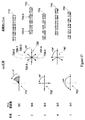
図3は、ビーム成形の前の超音波信号サンプルのプロットである。このプロットは、ADCアレイの1つのADCによってサンプリングされた4つのパルスエコーに対する同相サンプルを表示するものである。この例では、ビーム成形の前に、ADCから出力された超音波信号サンプルにデジタルダウン変換が適用されて、I、Qサンプルを形成している。図4は、1つのビーム成形出力チャンネルに対応するビーム成形超音波信号の同相サンプルのプロットである。この例では、ビーム成形器は、遅延及び重み付け関数をI、Qサンプルに適用することにより複数のADCから出力されたI、Qサンプルの複数のシーケンスを合成する。 FIG. 3 is a plot of ultrasound signal samples prior to beam shaping. This plot displays in-phase samples for four pulse echoes sampled by one ADC of the ADC array. In this example, before beam shaping, digital down conversion is applied to the ultrasonic signal samples output from the ADC to form I and Q samples. FIG. 4 is a plot of in-phase samples of the beam-shaping ultrasound signal corresponding to one beam-shaping output channel. In this example, the beam shaper combines a plurality of sequences of I and Q samples output from a plurality of ADCs by applying a delay and weighting function to the I and Q samples.
図5は、好ましい実施形態により、受信ビーム成形器160によって発生されたビーム成形サンプルを圧縮することを含む超音波画像形成システムのブロック図である。圧縮器210は、複数の圧縮ユニット210iを備え、その各々は、それに対応するビーム成形器出力チャンネル161iに圧縮オペレーションを適用する。圧縮ユニット210iは、特定のビームを表すビーム成形サンプルの1Dアレイに圧縮オペレーションを適用して、圧縮されたビーム成形サンプルの対応シーケンスを圧縮器の出力211iに発生する。特定のビームのビーム成形サンプルは、他のビームを表すビーム成形サンプルとは独立して圧縮される。或いは又、圧縮ユニット210iは、複数のビーム成形器出力チャンネル161iから受け取られた複数のビームを表すビーム成形サンプルを圧縮してもよい。この別の態様では、圧縮ユニット210iは、異なるビームを表すビーム成形サンプルに圧縮オペレーションを独立して適用する。圧縮されたビーム成形サンプルは、デジタルインターフェイス220を横切って診断情報プロセッサ180へ転送される。解凍器240は、受け取った圧縮データを解凍して、診断情報プロセッサ180による更なる信号処理オペレーションのためにビーム成形サンプルの1Dアレイを再構成する。圧縮されたビーム成形サンプルを転送するに必要なデジタルインターフェイス220のデータ転送帯域巾は、非圧縮のビーム成形サンプルを転送するに必要な帯域巾に比して減少される。
FIG. 5 is a block diagram of an ultrasound imaging system that includes compressing a beamformed sample generated by a receive
処理シーケンスのある時点で、処理された超音波信号がIF又は基本帯域へダウン変換される。ダウン変換は、ADCバンク120によるアナログ/デジタル変換の前又は後、ビーム成形の後であって且つ圧縮の前、或いは解凍の後に、適用されてもよい。ダウン変換が圧縮の前に適用されるときには、圧縮器210に入力されるビーム成形サンプルは、中心周波数を中間周波(IF)又はゼロ周波数(基本帯域)に有する。ダウン変換が解凍の後に適用されるときには、圧縮器210に入力されるビーム成形サンプルは、RF中心周波数を有する。ここでの説明は、ビーム成形サンプルが実数値のサンプルであることを仮定している。或いは又、ADC120iが直角位相サンプリングを遂行するか又は直角位相ダウン変換が圧縮の前に適用される場合には、ビーム成形サンプルがI及びQ成分を有する。この状態では、圧縮器210は、ビーム成形サンプルのI及びQ成分を独立して処理する。
At some point in the processing sequence, the processed ultrasound signal is down converted to IF or the fundamental band. Down conversion may be applied before or after analog / digital conversion by
圧縮されたビーム成形サンプルは、サンプル当たり少数のビットしかもたないので、デジタルインターフェイス220に接続するためのデータポートが、過剰な帯域巾を有することがある。圧縮されたビーム成形サンプルは、デジタルインターフェイス220を経て転送するための少数のデータチャンネルを形成するようにマルチプレクスされてもよい。図6は、少数のデータポートを横切って転送するために圧縮されたビーム成形サンプルをマルチプレクスすることを含む超音波システムのブロック図である。受信ビーム成形器160は、各ADC出力121iから超音波信号サンプルのN本のストリームX1ないしXNを受け取り、そしてビーム成形器出力チャンネル161iにJ本のビームB1ないしBJを発生する。圧縮ユニット210iは、圧縮されたビーム成形サンプルのJ本の対応ストリームC1ないしCJを発生する。減少ビットレートの圧縮されたビーム成形サンプルがデータポート270iに与えられる。好ましくは、データポート270iは、低電圧差動シグナリング(LVDS)データ送信を与える。或いは又、データポート270iは、データ送信のためのシリアライザ/デシリアライザ(serDes)インターフェイスを使用することができる。ナショナルセミコンダクタ社により2008年1月に出版された“LVDS Owner’s Manual Including High-Speed CML and Signal Conditioning”と題する文書、第4版には、LVDS装置及びアーキテクチャーが記述されている。LVDSデータ送信は、3.125Gbpsの最大データ転送レート、低ノイズ及び低電力消費を含む望ましい特性を有する。差動シグナリングは、正の差動出力について1つ及び負の差動出力について1つの、2つのI/Oピンをチャンネル出力当たりに要求し、これは、LVDS対と称される。データポート270iは、圧縮器出力Ciにおける圧縮ビームのビットレートがポートの最大データ転送レートより低いときには、過剰な帯域巾を有する。この過剰な帯域巾は、所与のデータポート270iを経て転送するために複数の圧縮ビームを合成することにより利用することができる。マルチプレクサ250は、圧縮されたビーム成形サンプルのJ個のシーケンスを合成して、M個のデータポート270iを経て転送するためのM個のマルチプレクスされたシーケンスDjを形成する。合成することのできる圧縮ビームの数は、データ転送ポート270iの帯域巾により制限される。シリアライザ260は、マルチプレクスされたビットシーケンスを、それに対応するデータポート270iに与える。
Since the compressed beamformed sample has only a few bits per sample, the data port for connection to the
圧縮されたビーム成形サンプルをマルチプレクスして、M個のデータポートを使用する効果は、より少数の物理的データポートを使用することを含み、これは、次いで、データポートの接続及び電力消費を減少する。圧縮されたビーム成形サンプルのビットレートが固定である用途では、マルチプレクサ250は、固定数の物理的データポート270iに対して固定数のマルチプレクサ出力251iを有する。或いは又、融通性のあるアーキテクチャーは、圧縮されたビーム成形サンプルのビットレートに基づいて固定数の物理的データポート270iの中で可変数のアクティブなデータポートをサポートすることができる。融通性のあるアーキテクチャーでは、圧縮器210は、ユーザ選択可能な圧縮比パラメータに基づく種々のビットレートで圧縮されたビーム成形サンプルを与える。圧縮コントローラ(図5には示されていない)は、オペレーションが希望の圧縮比に対応するビットレートで圧縮されたビーム成形サンプルを発生するように、圧縮コントロールパラメータを圧縮ユニット210iに与える。圧縮コントローラは、発生すべきマルチプレクスされたシーケンスの数Mを指示するためにマルチプレクスコントロールパラメータをマルチプレクサ250に与える。又、圧縮コントローラは、ユーザ入力に応答して、インアクティブなデータポートを電源オフし、電力を更に保存することができる。
The effect of multiplexing compressed beam-shaped samples and using M data ports includes using fewer physical data ports, which in turn reduces data port connectivity and power consumption. Decrease. For applications where the bit rate of the compressed beamformed sample is fixed, the
1つのデータポートに対して合成できる圧縮ビームの数は、データポート270iの帯域巾によって制限される。例えば、J=8本のビームBiに対して、各ビームが16ビット/ビーム成形サンプル、及び50メガサンプル/秒(Msps)のサンプルレートを有する場合に、各ビーム成形器出力チャンネル161iのビットレートは、800Mbpsである。データポート270iが800Mbpsまでのデータ転送レートを有し、そして圧縮器210が2:1の圧縮比を生じると仮定する。圧縮器出力211iにおける圧縮ビームCiは、400Mbpsのビットレートを有する。この場合に、1つのデータポート270iは、800Mbpsのデータ転送レートで2つの圧縮ビームCiを転送するに充分な帯域巾を有する。マルチプレクサ250は、1組の2つの圧縮ビームCi及びCi+1からの圧縮されたビーム成形サンプルを合成し、マルチプレクスされた圧縮サンプルDjの対応シーケンスを1つのマルチプレクサ出力251iに形成する。この例では、対応するアクティブなデータポートに与えられるマルチプレクスされたシーケンスの数は、M=J/2=4である。シリアライザ260は、ビットのシーケンスを対応データポート270iに与える。デジタルインターフェイス220を経て転送された後に、デマルチプレクサは、M個のマルチプレクスされたシーケンスを受け取り、そしてそれらをデマルチプレクスして、解凍器240に与えられるJ個の圧縮ビームを回復させる。或いは又、マルチプレクサ250は、グループ当たり固定数のサンプルを有する圧縮されたビーム成形サンプルのグループをインターリーブしてもよい。この別の形態では、解凍器240は、図12及び図13を参照して以下に述べるように、デマルチプレクシングの前に、圧縮されたビーム成形サンプルのグループを解凍することができる。
The number of compressed beams that can be combined for one data port is limited by the bandwidth of the data port 270i. For example, if the relative J = 8 beams B i, having a sample rate of each beam 16 bit / beam molded samples, and 50 mega-samples / second (Msps), bits of each
圧縮ユニット210iにより適用される圧縮方法は、各ビーム成形器出力チャンネル161iのビーム成形サンプルに、他のビームとは独立して、作用する。ビーム成形サンプルに適用される圧縮方法は、ビーム内の他のサンプルの値に依存する。圧縮方法は、ブロックフローティングポイントエンコーディングを行い、そしてビーム成形サンプルの第1又はそれより高次の導関数を計算し、それに続いて、ブロックフローティングポイントエンコーディングを行うことを含む。ブロックフローティングポイントエンコーディングに代わって、ハフマン又は他の形式のエンコーディングを行うこともできる。
The compression method applied by the
圧縮ユニット210iの好ましい実施形態は、ビーム成形器出力チャンネル161iからの連続的ビーム成形サンプルのグループにブロックフローティングポイントエンコーディングを適用し、各グループは、N_GROUPサンプルを有する。N_GROUPサンプルの最大指数がエンコードされ、そしてN_GROUPサンプルが次の段階に基づいてエンコードされる。
N_GROUPサンプルの第1グループの場合:
1)最大の大きさをもつサンプルの指数(底2)を、例えば、N_GROUPサンプルの各グループにおいて最大の大きさのlog2を計算することにより決定する。これは、エンコードされたサンプル当たりのビット数、又はn_exp(0)を指示する。
2)S個のビットを使用して第1グループの指数n_exp(0)を絶対エンコードする。ここで、Sは、サンプル当たりの元のビット数である。
3)サンプル当たりn_exp(0)ビットを使用してN_GROUPサンプルをエンコードする。
N_GROUPサンプルのi番目のグループの場合(i>0):
4)最大の大きさをもつサンプルのi番目の指数(底2)を決定する。これは、i番目のグループにおけるエンコードされたサンプル当たりのビット数、又はn_exp(i)を指示する。
5)n_exp(i−1)からn_exp(i)を減算することによりi番目の指数を差動エンコードし、i番目の差の値を決定する。対応するトークンを使用してi番目の差の値をエンコードする。但し、短いトークンは、共通性の多い差の値を表し、そして長いトークンは、共通性の少ない差の値を表す。
6)サンプル当たりn_exp(i)を使用してN_GROUPサンプルのi番目のグループをエンコードする。
A preferred embodiment of
For the first group of N_GROUP samples:
1) Determine the index (base 2) of the sample with the largest size, for example by calculating the largest size log 2 in each group of N_GROUP samples. This indicates the number of bits per encoded sample, or n_exp (0).
2) Absolutely encode the first group of exponents n_exp (0) using S bits. Here, S is the original number of bits per sample.
3) Encode N_GROUP samples using n_exp (0) bits per sample.
For i-th group of N_GROUP samples (i> 0):
4) Determine the i-th index (base 2) of the sample with the largest size. This indicates the number of bits per sample encoded in the i th group, or n_exp (i).
5) Subtract n_exp (i) from n_exp (i-1) to differentially encode the i-th exponent and determine the i-th difference value. Encode the i th difference value using the corresponding token. However, a short token represents a difference value with a high commonality, and a long token represents a difference value with a low commonality.
6) Encode the i th group of N_GROUP samples using n_exp (i) per sample.
第1のサンプルグループの場合に、指数n_exp(0)が直接エンコードされる。例えば、指数n_exp(0)は、次のようにエンコードすることができる。但し、Sは、サンプル当たりの元のビット数である。
a.0: n_exp(0)=0(4つのサンプル値は全てゼロ)
b.1: n_exp(0)=2(サンプル当たり2ビット)
c.2: n_exp(0)=3(サンプル当たり3ビット)
d.等、S−1まで: n_exp(0)=S(サンプル当たりSビット)
For the first sample group, the index n_exp (0) is directly encoded. For example, the index n_exp (0) can be encoded as follows. Where S is the original number of bits per sample.
a. 0: n_exp (0) = 0 (all four sample values are zero)
b. 1: n_exp (0) = 2 (2 bits per sample)
c. 2: n_exp (0) = 3 (3 bits per sample)
d. Etc., up to S-1: n_exp (0) = S (S bits per sample)
i番目のグループの場合に、指数n_exp(i)は、プレフィックスコードを使用して差動エンコードされ、但し、別のコードワードのプレフィックスとなるコードワードはない。好ましい差動エンコーディングは、次の通りである。
1.差を計算する:e_diff=n_exp(i)−n_exp(i−1)
2.e_diffを次のようにエンコードする:
a.0: e_diff=e(i)−e(i−1)
b.101: e_diff=+1
c.110: e_diff=−1
d.1001: e_diff=+2
e.1110: e_diff=−2
f.等
或いは又、指数n_exp(i)は、差動エンコードされるのではなく、ハフマンエンコードされてもよい。
For the i th group, the index n_exp (i) is differentially encoded using a prefix code, but there is no codeword that is a prefix of another codeword. A preferred differential encoding is as follows.
1. Calculate the difference: e_diff = n_exp (i) −n_exp (i−1)
2. Encode e_diff as follows:
a. 0: e_diff = e (i) −e (i−1)
b. 101: e_diff = + 1
c. 110: e_diff = −1
d. 1001: e_diff = + 2
e. 1110: e_diff = -2
f. Alternatively, the index n_exp (i) may be Huffman encoded rather than differentially encoded.
図7は、N_GROUP=4であるブロックフローティングポイントエンコーダのブロック図である。指数計算器402は、ステップ1及びステップ4のように、N_GROUPサンプルに対し、最大指数n_expをビットで決定する。指数トークンジェネレータ404は、ステップ2及びステップ5のように、n_exp値をエンコードする。仮数パッカー406は、ステップ3及びステップ6のように、N_GROUPサンプルに対する仮数をエンコードする。図8は、エンコーディングのためのサンプルのn_bitを選択する一例を示す。入力サンプル420は、Kビットで表される。サンプル420のn_exp下位ビットは、エンコーディングに対して選択される。選択されたビットにサンプルの符号ビットが添付され、それにより得られるビットシーケンスが仮数を表す。図7に戻ると、マルチプレクサ408は、エンコードされた指数トークン411及びそれに続くN_GROUP仮数をパックし、N_GROUP圧縮サンプルを表す圧縮グループ410を形成する。この例では、圧縮グループ410は、指数トークン411及びそれに続く4つのパックされた仮数のシーケンス412−0、412−1、412−2及び412−3を含む。圧縮ユニット210iは、連続する圧縮グループを連結して、圧縮器出力211iに圧縮パケットのデータ部分を形成する。N_GROUPの好ましいサイズは、グループ当たり3又は4個のサンプルである。しかしながら、可変グループサイズも使用できる。
FIG. 7 is a block diagram of a block floating point encoder with N_GROUP = 4. The
仮数及び指数を別々にエンコードすることで、付加的な圧縮を与え、そして圧縮エラーを軽減することができる。連続する指数の差の値が計算され、エンコードされる。指数はゆっくり変化し、従って、比較的僅かな非ゼロ値が、ゼロ値のストリングにより分離される。指数の差の値は、非ゼロの差の値及びそれに対応する位置だけを表すことにより効率的にエンコードすることができる。位置は、それに対応するインデックス値により、又は最後の非ゼロの差の値の位置に対して、表すことができる。指数の差の値のエンコーディングは、ロスレスであり、比較的大きなエラーを防止する。指数のデコーディングについては、指数値は、指数の差の値を積分しそしてそれに対応する位置場所をデコードすることにより再構成される。仮数のデコーディングについては、再構成された各仮数値は、デコードされたサンプルの対応する指数の値を変化させないように制限される。n_expのデコードされた指数については、再構成された仮数は、2n_exp−1の最大値をもつことができる。これは、仮数の圧縮エラーが指数の値を変化させるのを防止する。 Encoding the mantissa and exponent separately can provide additional compression and reduce compression errors. Successive exponent difference values are calculated and encoded. The exponent changes slowly, so that relatively few non-zero values are separated by a string of zero values. Exponential difference values can be efficiently encoded by representing only non-zero difference values and their corresponding positions. The position can be represented by its corresponding index value or relative to the position of the last non-zero difference value. The encoding of the exponent difference value is lossless and prevents relatively large errors. For exponent decoding, the exponent value is reconstructed by integrating the exponent difference value and decoding the corresponding location. For mantissa decoding, each reconstructed mantissa is constrained to not change the value of the corresponding exponent of the decoded sample. For a decoded exponent of n_exp, the reconstructed mantissa can have a maximum value of 2 n_exp −1. This prevents mantissa compression errors from changing the value of the exponent.
別のブロックフローティングポイントエンコーディング方法は、仮数を表すビットの数を減少しそして上述したように指数を差動エンコーディングすることを含む。N_GROUPサンプルの仮数を表すビットの数は、グループに対するn_expの値に基づいて、各仮数から最下位ビット(LSB)の数を選択的に除去することにより減少される。 Another block floating point encoding method includes reducing the number of bits representing the mantissa and differential encoding the exponent as described above. The number of bits representing the mantissa of the N_GROUP sample is reduced by selectively removing the least significant bit (LSB) number from each mantissa based on the value of n_exp for the group.
図9は、減少された仮数を表すためのビットを選択する一例を示す。n_expは、上述したステップ1及びステップ4のように決定される。仮数のn_exp下位ビットを全てエンコーディングするのではなく、最下位ビットでスタートしてビット数n_LSBが除去される。残りのm_expビット(m_exp=n_exp−n_LSB)がエンコーディングのために選択される。n_LSBの値は、式又はテーブルに基づきn_expの値に依存する。図10は、n_exp、n_LSB及びm_expの規範的な値を示すテーブルである。n_expのより大きな値について、m_expビットを有する減少された仮数を形成するように切断又は丸めることにより、より多くのLSBが除去される。例えば、n_expが12である場合には、3つのLSBが除去され、N_GROUPの減少された仮数をパッキングするために9つの仮数ビットが保持される。圧縮器210は、n_exp、n_LSB及びm_expの値のルックアップテーブルを記憶することができる。或いは又、圧縮器210は、n_LSB及びm_expをn_expの関数として表し、そして必要に応じてそれらの値を計算することができる。図11は、減少された仮数を使用するブロックフローティングポイントエンコーディングのブロック図である。N_GROUPサンプルの各グループに対して、指数計算器402は、上述したように、最大指数n_expを決定する。仮数ビット計算器414は、ルックアップテーブル又は式を使用して減少された仮数におけるビットの数m_expを決定する。減少された仮数のパッカー416は、N_GROUPサンプルの各々に対してm_expビットを選択する。次いで、マルチプレクサ408は、指数トークン411及びそれに続く減少された仮数419−0、419−1、419−2及び419−3をパックして、圧縮グループ418を形成する。ある条件については、N_GROUPサンプルのグループから除去されるLSBはない。例えば、N_GROUPサンプルにおける1つ以上のサンプルの大きさが許容最小値より小さいときには、元のLSBを含むN_GROUP仮数がパックされる。圧縮ビームは、減少された仮数を伴ったり伴わなかったりする圧縮グループを含むことができる。
FIG. 9 shows an example of selecting bits to represent the reduced mantissa. n_exp is determined as in
圧縮コントローラは、ブロックフローティングポイントエンコーディングに対して圧縮ユニット210iに圧縮コントロールパラメータを与える。n_LSB、m_exp及びn_expのための複数の別のルックアップテーブル又は式がある。圧縮コントロールパラメータは、n_LSB、m_exp及びn_expのための別のルックアップテーブル又は式に対してN_GROUP及び選択パラメータを含む。圧縮コントロールパラメータは、全ての圧縮ユニット210iに対して均一である。或いは又、圧縮コントロールパラメータは、異なる圧縮ユニット210iに対して異なる値をもつことができる。圧縮コントローラは、ユーザ入力に応答して、圧縮コントロールパラメータを選択することができる。
The compression controller provides compression control parameters to the
圧縮されたビーム成形サンプルは、デジタルインターフェイス220を経て転送するために圧縮パケットのデータ部分へ挿入することができる。サンプル窓に対応する圧縮ビームの圧縮されたビーム成形サンプルは、1つ以上の圧縮パケットに配列することができる。或いは又、図6を参照して述べたように、複数の圧縮ビームに対応する圧縮されたビーム成形サンプルのシーケンスを合成して、所与のデータポート270iを経て転送するための圧縮パケットを形成することもできる。圧縮パケットのヘッダ部分は、パケットのための識別情報を含む。又、ヘッダは、パケットにおける圧縮されたビーム成形サンプルの圧縮コントロールパラメータを表すコントロールデータも含むことができる。圧縮コントロールパラメータに関する情報は、解凍オペレーションを構成するように解凍器240により使用することができる。
The compressed beamformed sample can be inserted into the data portion of the compressed packet for transfer via the
図6のマルチプレクサ250の好ましい実施形態では、N_GROUP圧縮ビーム成形サンプルのグループがマルチプレクスされる。マルチプレクサ250は、J個の圧縮ビームの圧縮グループをインターリーブすることによりM個のマルチプレクスされたシーケンスを発生する。J個の圧縮ビームは、M組の圧縮ビームに分割される。各組に対して、マルチプレクサ250は、その組の圧縮ビームの圧縮グループをインターリーブして、それに対応するマルチプレクスされたシーケンスDmを形成する。マルチプレクスされたシーケンスDmは、マルチプレクサ250によりグループ順序で配列された対応する組からの圧縮グループのシーケンスである。マルチプレクサ250は、対応する組の圧縮ビームを各々受け取るM個の並列マルチプレクサとして具現化することができる。
In the preferred embodiment of
図12は、1組の圧縮ビームC1及びC2の圧縮グループをマルチプレクスする一例を示す。グループマルチプレクサ252は、圧縮ビームC1からの圧縮グループG1j及び圧縮ビームC2からの圧縮グループG2jをインターリーブして、マルチプレクスされたシーケンスD1を形成する。この例では、マルチプレクスされたシーケンスD1のグループ順序は、圧縮ビーム間で交番して、シーケンスG1j、G2j、G1(j+1)、G2(j+1)、等を形成する。圧縮グループGijは、図7のブロックフローティングポイント圧縮グループ410、図11の圧縮グループ418、又はハフマンエンコーディングのような別のエンコーディング方法から生じる圧縮グループに対応するパックされたビットを表す。圧縮グループは、グループ当たり同じ数の圧縮されたビーム成形サンプル、即ちN_GROUPサンプルを有する。しかしながら、圧縮サンプル当たりのビットの数が変化するので、圧縮グループ当たりのビットの数も変化する。上述したブロックフローティングポイントエンコーディング方法については、圧縮グループ当たりのビットの数は、n_expの値に依存する。
FIG. 12 shows an example of multiplexing a compressed group of a set of compressed beams C 1 and C 2 . The
解凍については、解凍器240は、各圧縮ビームに対応する圧縮グループの圧縮されたビーム成形サンプルをデコードし、アンパックする。N_GROUP圧縮ビーム成形サンプルの各グループについては、解凍器240は、指数トークンをデコードして、n_expの値を決定する。差動エンコードされた指数は、積分されて、n_expの値を形成する。次いで、圧縮グループ410又は418からの各仮数に対するビットをアンパックしそして各解凍されたビーム成形サンプルへビットをマップして、解凍グループを形成することにより、N_GROUP仮数が再構成される。解凍されたビーム成形サンプルは、ビーム成形サンプル当たりの元のビット数により、又は下流の処理要件に基づきビーム成形サンプル当たりの異なるビット数により、表すことができる。減少仮数を使用するブロックフローティングポイントエンコーディングについては、解凍器240は、n_expのデコード値に基づいてn_LSBの値を決定するためのルックアップテーブル又は式も含む。減少仮数に対するアンパックされたビットには、元のビーム成形サンプル値を近似するためにゼロ又はディザ値であるn_LSBビットが添付される。特定の圧縮ビームから計算された解凍グループのシーケンスは、それに対応する解凍ビームを形成する。
For decompression,
圧縮グループのマルチプレクスされたシーケンスの解凍については、解凍器240が、デマルチプレクシングの前に、マルチプレクスされたシーケンスに適用される。図13を参照すれば、マルチプレクスされたシーケンスD1の各圧縮グループGijは、そのグループのN_GROUP圧縮ビーム成形サンプルを解凍するための必要な情報を与える指数トークンを含む。差動エンコードされる指数トークンについては、解凍器は、マルチプレクスされたシーケンスD1のグループ順序を使用して、積分のために同じ圧縮ビームに対応する指数トークンを選択し、n_expの対応値を決定する。グループ順序は、マルチプレクシング及びデマルチプレクシングのための固定パラメータであり、この場合に、それは、解凍器240及びグループデマルチプレクサ254には知られている。或いは又、グループ順序は、調整可能なパラメータでもよく、この場合に、それは、他の圧縮パラメータと共に、圧縮パケットのヘッダ部分に含ませることができる。上述したように、圧縮グループは、異なるビット数を有してもよい。しかしながら、グループが解凍されると、各グループに対するN_GROUP解凍ビーム成形サンプルは、サンプル当たり同じビット数を有する。解凍グループのグループ順序は、圧縮グループと同じである。グループデマルチプレクサ254は、解凍グループをそれらの元の順序へ再順序付けし、解凍されたビーム成形サンプルを元の連続順序で各々有する1組の解凍ビームを形成する。
For decompression of a compressed group of multiplexed sequences,
図13は、図12のマルチプレクス例に対応するデマルチプレクス例を示す。解凍器240は、マルチプレクスされたシーケンスD1にブロックフローティングポイントデコーディングを適用して、解凍グループ241のシーケンスを形成する。各グループRijにおける解凍されたビーム成形サンプルは、サンプル当たり同じビット数を有する。グループデマルチプレクサ254は、解凍されたビーム成形サンプルのグループに対して元の順序を回復し、解凍ビーム253及び255の組を形成する。グループデマルチプレクサ254は、グループ順序、即ちR1j、R2j、R1(j+1)、R2(j+2)、等を使用して、解凍されたビーム成形サンプルのグループをそれらの各々の解凍ビーム253及び255へ分離する。グループ当たりのサンプル数は、N_GROUPであるから、グループデマルチプレクサ254は、各グループRijのN_GROUP解凍ビーム成形サンプルをそれに対応する解凍ビームに添付する。
FIG. 13 shows an example of demultiplexing corresponding to the example of multiplexing shown in FIG. The
ビーム成形サンプルを圧縮及び解凍するための別の方法は、振幅が低く、それ故、表現するのに僅かなビットしか必要としない変更サンプルを発生する前に各ビーム内のビーム成形サンプルに対して計算を遂行することを含む。‘533特許は、ある帯域制限信号を圧縮及び解凍するためのアルゴリズムについて述べている。以下に述べる別の圧縮方法の幾つかは、ビーム成形サンプルに関する‘533特許のアルゴリズムの変更である。 Another method for compressing and decompressing beam-shaped samples is for the beam-shaped samples in each beam before generating modified samples that have low amplitude and therefore require only a few bits to represent. Including performing calculations. The '533 patent describes an algorithm for compressing and decompressing certain band limited signals. Some of the other compression methods described below are modifications to the '533 patent algorithm for beamformed samples.
ビーム成形サンプルを圧縮するための別の方法は、各ビームにおけるビーム成形サンプル間の差を他のビームとは独立して計算し、それに続いて、エンコーディングを行うことを含む。ビーム成形サンプルの第1又はそれより高次の差を計算することで、元のビーム成形サンプルより大きさが小さい差のサンプルを得ることができる。差のサンプルをエンコードすることにより、ビーム成形サンプルそれ自体をエンコードする場合より大きな圧縮を得ることができる。 Another method for compressing beamformed samples involves calculating the difference between beamformed samples in each beam independently of the other beams, followed by encoding. By calculating the first or higher order difference of the beam-shaped sample, a difference sample that is smaller in size than the original beam-shaped sample can be obtained. By encoding the difference sample, a greater compression can be obtained than when the beam-shaped sample itself is encoded.
図14は、差の演算を含む圧縮ユニット210iのブロック図である。圧縮ユニット210iは、ビーム成形器出力チャンネル161iからビーム成形サンプルを受け取る。圧縮コントローラ340は、各圧縮ユニット210iの差の演算器330i及びエンコーダ332iに対する圧縮コントロールパラメータを与える。差の演算器330iの圧縮コントロールパラメータは、第1、第2又はそれより高次の差を選択することができる。差の演算器330iは、選択された差の順序を適用して、差のサンプルを発生する。又、圧縮コントロールパラメータは、エンコーダ332iが差のサンプルではなくビーム成形サンプルをエンコードするように、差の演算をバイパスするよう選択することもできる。エンコーダ332iは、上述したように、差のサンプルのブロックフローティングポイントエンコーディングを適用することができる。この場合に、図7又は図11のブロックフローティングポイントエンコーダの入力401に差のサンプルが与えられる。或いは又、エンコーダ332iは、ハフマンエンコーディング又は他のエンコーディングを異なるサンプルに適用してもよい。エンコーダ332iの圧縮コントロールパラメータは、上述したように、ブロックフローティングポイントエンコーダのパラメータを指示するか、又はハフマンエンコーダ又は別のエンコーダのパラメータを指示することができる。圧縮コントロールパラメータは、異なる圧縮ユニット210iに対して同じものでも、異なるものでもよい。
FIG. 14 is a block diagram of a
異なる圧縮ビームに対応する圧縮器出力211iは、図6及び図12を参照して上述したように、デジタルインターフェイス220を経て転送する前に、少数の出力チャンネルへとマルチプレクスされる。エンコーダ332iは、ブロックフローティングポイントエンコーディングを異なるサンプルに適用して、圧縮ビームC1及びC2より成るN_GROUPエンコード化の差のサンプルのグループを表す図12の圧縮グループGijを発生することができる。或いは又、エンコーダ332iは、ハフマンエンコーディングを差のサンプルに適用して、圧縮グループ当たりN_GROUP圧縮ビーム成形サンプルを有するハフマンエンコード化の差のサンプルのグループをGijが表すようにすることもできる。グループマルチプレクサ252は、圧縮ビームC1及びC2の圧縮グループを合成して、マルチプレクスされたシーケンスD1を形成する。
The compressor outputs 211i corresponding to the different compressed beams are multiplexed into a small number of output channels before being transferred through the
図15は、図14を参照して述べた圧縮オペレーションに対応する解凍オペレーションのブロック図である。解凍器240は、デジタルインターフェイス220から圧縮ビームを受け取る。デコーダ352は、エンコーダ332iのオペレーションを逆に行い、デコードされた差のサンプルを形成する。例えば、デコーダ352は、ブロックフローティングポイントデコーディング、ハフマンデコーディング、又は他のデコーディングを遂行する。積分演算器354は、デコードされた差のサンプルを加算して、圧縮のために遂行される第1又はそれより高次の差の演算を逆に行い、診断情報プロセッサ180に与えられる解凍ビームを形成する。圧縮に対して差の演算が行われない場合には、積分演算器354がバイパスされる。解凍コントローラ350は、デコーダ352及び積分演算器354にコントロールパラメータを与える。解凍コントローラ350は、圧縮データパケットのヘッダからコントロールデータを抽出して、解凍オペレーションのためのコントロールパラメータを決定する。
FIG. 15 is a block diagram of a decompression operation corresponding to the compression operation described with reference to FIG. The
図15の解凍器240は、図13を参照して述べたように、デマルチプレクシングの前に、差のサンプルの圧縮グループのマルチプレクスされたシーケンスに適用される。この場合には、デコーダ352は、マルチプレクスされたシーケンスで圧縮グループGijをデコードし、デコードされた差のサンプルのグループをグループ順序で形成する。ブロックフローティングポイントデコーディングについては、指数トークンが差動エンコードされる場合に、デコーダ352は、グループ順序を使用して、同じビームに対応する指数トークンを積分し、対応するグループのn_exp値を決定する。積分演算器354は、グループ順序及びn_expを使用して、同じビームに対応するデコードされた差のサンプルのグループを決定する。積分演算器354は、各グループのデコードされた差のサンプルを積分して、241のシーケンスの解凍グループRijを形成する。次いで、グループデマルチプレクサ254は、解凍グループRijを各解凍ビーム253及び255へ分離する。
The
或いは又、デコードされた差のサンプルのグループは、図16に示すように、積分の前に、デマルチプレクスされてもよい。デコーダ352は、図12にD1で表されたようなマルチプレクスされたシーケンスを受け取る。デコーダ352は、エンコーダ332iのオペレーションを逆に行い、圧縮グループをアンパック及びデコードして、デコードされた差のサンプルのグループをグループ順序で形成する。指数トークンが差動エンコードされるブロックフローティングポイントデコーディングについては、デコーダ352は、グループ順序を使用して、同じビームに対応する指数トークンを積分する。デコードされた差のサンプルのグループは、サンプル当たり同じビット数を有し、そして圧縮グループのマルチプレクスされたシーケンスに対応するグループ順序にある。グループデマルチプレクサ254は、デコードされた差のサンプルのグループを分離して、各ビームに対応するデコードされた差のサンプルのアレイを形成する。各アレイにおけるデコードされた差のサンプルの順序は、差の演算器330iから出力される差のサンプルの順序に対応する。積分演算器354i及び354jは、デコードされた差のサンプルの各アレイの第1又はそれより高次の積分を遂行して、i番目及びj番目の解凍ビームを形成する。
Alternatively, the group of decoded difference samples may be demultiplexed prior to integration, as shown in FIG.
圧縮のための別の態様では、振幅の低いサンプルを発生するために中心周波数及びサンプルレートに基づいてビーム成形サンプルに算術演算を適用する。図17は、異なる中心周波数をもつビーム成形サンプルを圧縮するための原理に基づく別々の例を示す。図17において「帯域1」と示された行に対応する基本帯域信号の例から始めると、中心周波数は、ほぼDC(0Hz)であり、連続サンプル間の位相増加は、10°未満である。第1のフェーザ図710は、連続サンプル間の位相変化が小さいので、連続サンプルの差の大きさがサンプルそれ自体の大きさに比較して比較的小さいことを示している。第1の規範的シーケンス712は、帯域1の基本帯域信号のサンプルに対応する。連続サンプル間の差がサンプルの大きさに対して小さいので、第1又はより高次の差を計算するか又は差動エンコーディングすると、元のサンプルより小さいデータ巾をもつ差のサンプルが生成される。図14を参照して述べた差動エンコーディングを使用する圧縮は、基本帯域(帯域1)の例について効果的である。超音波信号サンプル又はビーム成形サンプルが基本帯域へダウン変換される超音波システムでは、圧縮ユニット210iは、差動エンコーディングを適用する。
In another aspect for compression, arithmetic operations are applied to the beamformed samples based on the center frequency and sample rate to generate low amplitude samples. FIG. 17 shows separate examples based on the principle for compressing beam-shaped samples with different center frequencies. Starting with the example of the baseband signal corresponding to the row labeled “
又、図17は、中心周波数がDCよりは高いが、ナイキスト周波数fs/2よりは低いサンプル信号の例も示している。帯域2の場合に、中心周波数は、ほぼfs/6であり、連続サンプル間の位相増加は、約60°である。第2のフェーザ図720は、180°又は3つのサンプルインターバルだけ分離されたサンプルの対が、同様の大きさを有するが、逆の極性であることを示しており、これは、サンプル対(720−0、720−3)、(720−1、720−4)及び(720−2、720−5)により示されている。対におけるサンプルの1つを反転すると(又は(−1)を乗算すると)、その対における他のサンプルの厳密な推定が与えられる。第2の規範的シーケンス722も、3つのサンプルインターバルだけ分離されたサンプルが同様の大きさ及び逆の符号を有することを示している。例えば、サンプル722−0の値は、32767であり、そしてサンプル722−3の値は、−32756である。帯域2の場合に、3つのサンプルインターバルだけ分離されたサンプルの対に対するオペレーションは、小さなデータ巾の変更サンプルを発生する。対においてサンプルを追加するオペレーションは、より効率的にエンコードできる小さなデータ巾の変更サンプルを発生する。
FIG. 17 also shows an example of a sample signal whose center frequency is higher than DC but lower than the Nyquist frequency f s / 2. For
図17における帯域3の例では、中心周波数がほぼfs/4であり、連続サンプル間の位相増加が約90°である。第3のフェーザ図730は、180°又は2つのサンプルインターバルだけ分離されたサンプルが、同様の大きさ及び逆の極性を有することを示している。又、第3の規範的シーケンス732は、1つおきのサンプルが同様の大きさ及び逆の極性を有することを示している。帯域3の場合に、1つおきのサンプルを一緒に加算すると、元のサンプルより効率的にエンコードできる小さなデータ巾の変更サンプルが生じる。
In the example of
図17における帯域4の例では、中心周波数がほぼfs/3であり、連続サンプル間の位相増加が約120°である。第4のフェーザ図740は、360°又は3つのサンプルインターバルだけ分離されたサンプルが同様の大きさを有することを示している。第4の規範的シーケンス742は、2つおきのサンプルが同様の大きさを有することを示している。この場合に、3つのサンプルインターバルだけ分離されたサンプル間の差を形成することで、元のサンプルより効率的にエンコードできる小さなデータ巾の変更サンプルが得られる。
In the example of
図17における帯域5の例では、中心周波数がほぼfs/2であり、連続サンプル間の位相増加が約180°である。第5のフェーザ図750は、180°又は1つのサンプルインターバルだけ分離されたサンプルが同様の大きさを有するが極性が逆であることを示している。第5の規範的シーケンス752は、連続サンプルが同様の大きさ及び逆の極性を有することを示している。この場合に、2つの連続サンプルを加算することで、元のサンプルより効率的にエンコードできる小さなデータ巾の変更サンプルが形成される。
In the example of
図17について述べた前記例は、サンプルレートと中心周波数との比に基づいて、1つ、2つ又は3つのサンプルインターバルだけ分離されたビーム成形サンプルに対して加算(又は反転の後に減算)又は減算(又は反転の後に加算)のようなオペレーションを遂行することにより大きさ減少を達成できることを示している。それにより得られる変更サンプルは、次いで、圧縮サンプルを形成するようにエンコードされる。中心周波数とサンプルレートとの比に基づいて、4つ以上のサンプルインターバルだけ分離されたサンプルに同様のオペレーションを適用して、元のサンプルより小さなデータ巾の変更サンプルを発生することができる。 The example described with respect to FIG. 17 adds (or subtracts after inversion) or adds to beamformed samples separated by one, two or three sample intervals based on the ratio of sample rate to center frequency. It shows that size reduction can be achieved by performing operations such as subtraction (or addition after inversion). The resulting modified sample is then encoded to form a compressed sample. Based on the ratio between the center frequency and the sample rate, a similar operation can be applied to samples that are separated by more than four sample intervals to generate a modified sample with a smaller data width than the original sample.
図18は、ビーム成形サンプルの中心周波数に基づく圧縮アルゴリズムのブロック図である。特定のビームに対応するビーム成形器出力チャンネル161iは、再順序付けデマルチプレクサ810へ入力される。再順序付けデマルチプレクサ810は、選択されたサンプルが圧縮コントロールパラメータ852に基づいて適当な数のサンプルインターバルだけ分離されてデマルチプレクサ出力812を形成するようにビーム成形サンプルを選択する。算術演算器830は、圧縮コントロールパラメータ856に基づいてデマルチプレクサ出力サンプル812の対に対して加算又は減算演算を行って、変更サンプル832を形成する。又、算術演算器830は、デマルチプレクサ出力サンプル812に対してより高次の差を得るように構成することもできる。エンコーダ840は、変更サンプル832をエンコードして、圧縮されたビーム成形サンプルを形成する。エンコーダ840は、ブロックフローティングポイントエンコーディング、ハフマンエンコーディング、又は他のエンコーディングを適用して、圧縮サンプルを形成する。図7及び11を参照して説明したブロックフローティングポイントエンコーディングについては、ブロックフローティングポイントエンコーダの入力401に変更サンプル832が与えられる。
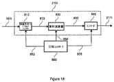
FIG. 18 is a block diagram of a compression algorithm based on the center frequency of the beam-shaped sample. The beam
圧縮コントローラ860は、ビーム成形サンプルのサンプルレートと中心周波数との比に基づいて圧縮器要素にコントロールパラメータを与える。再順序付けデマルチプレクサ810及び算術演算器830は、各々、圧縮コントロールパラメータ852及び856に応答して、適当なオペレーションを遂行する。図19は、中心周波数に基づき変更サンプル832を発生するオペレーションを示す。第1の列871は、この例について考えられる中心周波数を示す。第2の列872は、各中心周波数に対する対応周波数帯域指示子を示す。指示子は、圧縮コントロール852及び856のためのパラメータとして使用することができる。第3の列873は、圧縮コントロールパラメータ852に基づいて発生されるサンプルx(i)及びx(i−j)の異なる分離を再順序付けデマルチプレクサ出力812に与える。第4の列874は、圧縮コントロールパラメータ856に基づき加算又は減算の算術演算を選択する結果を示す。インバータが遅延サンプルを「オン」にするときに、x(i−j)が減算される。第5の列875は、変更サンプル832を発生する算術演算器830の数学的結果、又はy(i)を示す。又、圧縮コントローラ860は、エンコーダ840のコントロールも与える。圧縮コントロールパラメータ858は、ブロックフローティングポイントエンコーディング、ハフマンエンコーディング、又は他のエンコーディング技術のためのパラメータを示すことができる。
The
図20は、異なる中心周波数について図18及び図19を参照して述べたように計算される図17の例に対するサンプルx(i)及びx(i−j)の和又は差を示す。サンプルの規範的なシーケンスは、図17と同じである。規範的シーケンス912及び942におけるDIFF(差)の行、並びに規範的シーケンス922、932及び952におけるSUM(和)の行のサンプルは、それに対応するサンプルより実質的に低い大きさ、又はx(i)を有する。DIFFサンプル及びSUMサンプルは、図18のエンコーダ840へ入力される変更サンプル932の例である。
FIG. 20 shows the sum or difference of samples x (i) and x (i−j) for the example of FIG. 17 calculated as described with reference to FIGS. 18 and 19 for different center frequencies. The normative sequence of samples is the same as in FIG. The samples in the DIFF (difference) row in the
図18のエンコーダ840により圧縮器出力211iに発生される圧縮ビームは、図6及び図12を参照して上述したように、デジタルインターフェイス220を経て転送する前に、他の圧縮ビームとマルチプレクスされて、少数の出力チャンネルを形成する。エンコーダ840は、ブロックフローティングポイントエンコーディングを変更サンプルに適用して、図12の圧縮グループGijが、圧縮ビームC1及びC2を形成するためにN_GROUPエンコード化変更サンプルを表すようにする。或いは又、エンコーダ840は、ハフマンエンコーディングを変更サンプルに適用して、Gijが、グループ当たりN_GROUPハフマンエンコード化変更サンプルを有する圧縮グループを表すようにしてもよい。グループマルチプレクサ252は、圧縮ビームC1及びC2の圧縮グループを合成して、マルチプレクスされたシーケンスD1を形成する。
The compressed beam generated at the
図21は、図18を参照して述べた圧縮方法に対して解凍器240により遂行されるオペレーションのブロック図である。デコーダ910は、アンパックすると共に、圧縮データに対して、例えば、ブロックフローティングポイントデコーディングのようなデコーディングオペレーションを遂行し、デコードされた変更サンプルを形成する。逆算術演算器920は、算術演算器830とは逆の演算を遂行して、デコードされた変更サンプルからビーム成形サンプルを再構成する。マルチプレクサ930は、解凍されたビーム成形サンプルに対して元のサンプル順序を回復して、それに対応する解凍ビームを形成する。解凍コントローラ940は、デコーダ910、逆演算器920及び順序回復マルチプレクサ930にコントロールパラメータを与える。解凍コントローラ940は、圧縮データパケットのヘッダからコントロールデータを抽出し、解凍オペレーションのためのコントロールパラメータを決定することができる。
FIG. 21 is a block diagram of operations performed by
図21の解凍器240は、グループをデマルチプレクスする前に変更サンプルの圧縮グループのマルチプレクスされたシーケンスに適用することができる。デコーダ910は、エンコーダ840のオペレーションを逆に行い、デコードされた変更サンプルのグループを形成する圧縮グループをグループ順序でデコードする。指数トークンが差動エンコードされるブロックフローティングポイントデコーディングでは、デコーダ910は、グループ順序を使用して、指数トークンを積分し、同じビームに対応する圧縮グループのn_exp値を決定する。又、逆演算器920及び順序回復マルチプレクサ930は、グループ順序及びn_expを使用して、それらの各オペレーションを、同じビームに対応するデコードされた変更サンプルのグループに適用させる。順序回復マルチプレクサ930は、各グループ内の解凍されたビーム成形サンプルを元のサンプル順序へ再順序付けして解凍グループを形成するが、解凍グループは、依然、グループ順序にある。図13を参照すると、順序回復マルチプレクサの出力は、解凍シーケンス241の解凍グループRijに対応する。グループデマルチプレクサ254は、解凍グループRijを、それに対応する解凍ビーム253及び255へと分離する。
The
或いは又、デコードされた変更サンプルのグループは、図22に示すように、逆演算器920の前にデマルチプレクスされてもよい。デコーダ910は、エンコーダ840のオペレーションを逆に行って、圧縮グループをアンパック及びデコードし、デコードされた差のサンプルの対応グループをグループ順序で形成する。指数トークンが差動エンコードされるブロックフローティングポイントデコーディングでは、デコーダ910がグループ順序を使用して指数トークンを積分し、同じビームに対応する圧縮グループのn_exp値を決定する。デコードされた変更サンプルのグループは、変更サンプル当たり同じビット数を有する。グループデマルチプレクサ254は、デコードされた変更サンプルのグループを分離して、各ビームに対応するデコードされた変更サンプルのアレイを形成する。逆演算器920i及び920jは、デコードされた変更サンプルの各アレイに適用され、そして順序回復マルチプレクサ930i及び930jは、各々、元のサンプル順序を回復して、i番目及びj番目の解凍ビームを形成する。
Alternatively, the decoded group of modified samples may be demultiplexed before the
圧縮器210の実施形態は、ビーム成形サンプルに単純なオペレーションを適用する。差の演算器330i(図14)は、1つ以上の減算器を含む。ブロックフローティングポイントエンコーディング(図7及び図11)は、比較器、減算器及びルックアップテーブルを使用する。或いは又、ハフマンエンコーディングは、ルックアップテーブルを使用して、値にコードを指定する。図18を参照して述べる圧縮オペレーションは、デマルチプレクシング、加算及び減算を含む。解凍器240の実施形態は、圧縮サンプルを解凍するために単純なオペレーションを適用する。解凍器240は、ブロックフローティングポイントデコーディングのためのルックアップテーブル及び加算器を含む。積分演算器354(図15)は、デコードされたサンプルを積分するための1つ以上の加算器を含む。図21の解凍器240のオペレーションは、加算、減算及びマルチプレクシングを含む。
The embodiment of the
超音波システムにおける本発明の好ましい具現化では、圧縮器210及び受信ビーム成形器160を単一の特定用途向け集積回路(ASIC)装置に一体化し、ADC出力チャンネル121iから超音波信号サンプルを受信するように入力データチャンネルを結合する。圧縮器210の好ましい具現化では、複数の圧縮コアを並列に含み、各圧縮コアは、ビーム成形器出力チャンネル161iの1つに結合され、対応するビームに対する1つの圧縮ユニット210iの圧縮オペレーションを具現化する。或いは又、1つの圧縮コアが複数のビームを圧縮するように複数の圧縮ユニット210iを具現化することもできる。この別の態様では、圧縮コアは、異なるビームに対応するビーム成形サンプルを、それらが処理されるまで記憶するためのバッファを含む。又、フィールドプログラマブルゲートアレイ(FPGA)においてビーム成形及び圧縮オペレーションを具現化することもできる。圧縮されたビーム成形サンプルは、LVDSポート270iを経てデジタルインターフェイス220へ出力することができる。LVDSインターフェイスのIPコアは、ASIC及びFPGA具現化に商業的に利用できるものである。別のアーキテクチャーは、圧縮器210を、受信ビーム成形器160とは個別の装置において具現化することを含む。圧縮器210は、ASIC、FPGA、又はプログラマブルプロセッサ、例えば、デジタル信号プロセッサ(DSP)、マイクロプロセッサ、マイクロコントローラ、マルチコアCPU(IBMセルのような)、又はグラフィック処理ユニット(GPU;例えば、Nvidia GeForce)において具現化することができる。
In a preferred embodiment of the present invention in an ultrasound system, the
超音波システムのアーキテクチャーに基づいて、解凍器240は、診断情報プロセッサ180と同じ装置又はそれとは異なる装置に合体されてもよい。解凍オペレーションは、ASIC又はFPGAにおいて具現化することができる。或いは又、解凍オペレーションは、DSP、マイクロプロセッサ、マイクロコントローラ、CPU又はGPUのようなプログラマブルプロセッサにより実行可能なソフトウェア又はファームウェアプログラムで具現化することもできる。解凍器240の好ましい具現化は、GPUにより実行可能な解凍オペレーションのインストラクションを有するソフトウェアプログラムである。又、GPUは、診断情報プロセッサ180及びスキャンコンバータ140のオペレーションの少なくとも一部分を具現化するようにプログラムされてもよい。或いは又、解凍されたビーム成形サンプルは、付加的な信号処理オペレーションのためにCPUのような別のプログラマブルプロセッサへ転送されてもよい。
Based on the architecture of the ultrasound system, the
図23は、解凍器240のGPUにおける具現化、及び超音波画像を発生するための他のオペレーションを示すブロック図である。現在のGPUアーキテクチャーは、並列計算に対して最適化された複数の処理コアを含む。例えば、Nvidia GeForce GTS 150 GPUは、128個の処理コアを備えている。Nvidiaの“CUDA”(コンピュート・ユニファイド・デバイス・アーキテクチャー)は、GPUの処理コアにおいて並列アルゴリズムを具現化するためにC言語への拡張を含むアプリケーションプログラミングインターフェイス(API)であり、2008年、Nvidia社のRuetsch及びOster著の“Getting Started with CUDA”と題する文書に説明されている。以下に述べるOpenCL及びLarrabeeのような別のGPU及びプログラミング方法は、具現化プラットホームを与える。図23に示す具現化では、GPU装置1000は、解凍器240、診断情報プロセッサ180(Bモード処理及びドップラー処理)、スキャンコンバータ140、及び画像プロセッサ150のオペレーションを実行するようにプログラムされる。GPU装置1000は、並列処理ユニットによりアクセスできるダイナミックランダムアクセスメモリ(DRAM)1002を含む。このDRAM1002は、GPUの他の処理オペレーションから生じる圧縮及び/又は解凍されたビーム成形サンプル及びデータを記憶する。システムコントローラ1010は、受け取ったデータから超音波画像を発生するためのタスクの整合を与え、そしてユーザのコマンドに応答する。CPU1012は、解凍をサポートするオペレーションを具現化し、例えば、圧縮されたパケットのヘッダから圧縮コントロールパラメータをデコードし、そしてそれらをGPU装置1000へ供給して解凍オペレーションを構成する。DRAM1016は、デジタルインターフェイス220から受け取った圧縮されたビーム成形サンプル及びCPUオペレーションに必要な他のデータを記憶する。通信コントローラ1014は、デジタルインターフェイス220から受け取った圧縮パケットをDRAM1002又はDRAM1016へ向けると共に、システムコントローラ1010とGPU装置1000との間のデータ交換を管理する。
FIG. 23 is a block diagram illustrating implementation of
好ましいシステムアーキテクチャーにおいて、システムコントローラ1010は、ディスプレイ160のためのスクリーンを有するコンピュータのマザーボードにおいて具現化される。GPU装置1000は、PCIe(ペリフェラル・コンポーネント・インターコネクト・エクスプレス)バックプレーンリンクによってシステムコントローラ1010と通信するDRAM1002を含むグラフィックカードにおいて実施される。或いは又、GPU装置1000は、マザーボードにマウントされたICにおいて実施されてもよい。ADCバンク120、受信ビーム成形器160及び圧縮器210がデータ取得カードにマウントされるシステムアーキテクチャーでは、デジタルインターフェイス220がPCIeバックプレーンリンクにより実施される。
In the preferred system architecture, the
ムーアの法則によれば、集積レベルが高いほど、よりコンパクトな装置となり、システムコントローラ1010及びGPU装置1000を単一のICで具現化できるようになることが明らかである。例えば、インテル社は、ベクトル処理装置で増強されたx86CPUコアの複数のインスタンス化を含む多コアICアーキテクチャーを開発している。ララビー(Larrabee)と称されるこのアーキテクチャーは、2008年8月、ACM Transactions on Graphics、第27巻、第3号、第18条に掲載されたシーラー氏等の“Larrabee: A Many-Core x86 Architecture for Visual Computing”と題する文書に述べられている。ララビーアーキテクチャーは、グラフィック処理を含めて並列処理を要求するアプリケーションをサポートする。「ララビーネーティブ」プログラミングモデルは、並列プログラミング及びベクトル化のためのC/C++及びAPIを含む。
According to Moore's Law, it is clear that the higher the integration level, the more compact the device, and the
図24は、解凍器240のCPU/GPU装置における具現化、及び超音波画像を発生するための他のオペレーションを示すブロック図である。CPU/GPU装置1020は、解凍器240、診断情報プロセッサ130、スキャンコンバータ140、及び画像プロセッサ150のオペレーションを具現化することができる。CPU/GPUコントローラ1022は、デジタルインターフェイス220から受け取られた圧縮されたビーム成形サンプルに対する処理オペレーションを整合し、そしてユーザ入力に応答する。CPU/GPU装置1020は、ララビープラットホームによるか、或いはCPU及びGPU一体化機能を伴う他のプログラマブル装置によって具現化される。
FIG. 24 is a block diagram illustrating implementation of the
ADCバンク120、受信ビーム成形器160及び圧縮器210がトランスジューサヘッドに収容されるシステムアーキテクチャーでは、デジタルインターフェイス220は、ワイヤード又はワイヤレス通信リンクである。ワイヤード通信リンクの場合に、デジタルインターフェイスは、PCIeケーブルリンク又は光ファイバリンクによって具現化される。ワイヤレス通信リンクでは、デジタルインターフェイスは、高周波チャンネルを経て圧縮パケットのデジタル変調及び送信を与えると共に、受け取った圧縮パケットのデジタル復調を与える。ワイヤレスリンクは、WiFi(IEEE802.11)又はUWB(ウルトラワイドバンド)フォーマットのようなワイヤレス通信プロトコルに適合する。
In a system architecture where the
以上、本発明の好ましい実施形態を図示して説明したが、本発明は、それらの実施形態のみに限定されないことが明らかである。当業者であれば、特許請求の範囲に規定される本発明の精神及び範囲から逸脱せずに、多数の修正、交換、変更、置き換え及び等効物が明らかとなろう。 While the preferred embodiments of the present invention have been illustrated and described above, it is clear that the present invention is not limited to only those embodiments. Numerous modifications, changes, changes, substitutions and equivalents will become apparent to those skilled in the art without departing from the spirit and scope of the invention as defined in the claims.
120:ADCバンク
121i:圧縮器出力
140:スキャンコンバータ
160:受信ビーム成形器
161i:ビーム成形器出力チャンネル
180:診断情報プロセッサ
210:圧縮器
210i:圧縮ユニット
220:デジタルインターフェイス
240:解凍器
250:マルチプレクサ
260:シリアライザ
270i:データポート
120: ADC bank 121i: Compressor output 140: Scan converter 160: Receive
Claims (11)
前記圧縮ビームを、デジタルインターフェイスを横切って信号プロセッサへと転送する段階と、
を備え、
前記圧縮する段階が、さらに、
前記特定ビームに対応する前記ビーム成形サンプルのアレイにおける連続的なビーム成形サンプルをグループにグループ化する段階であって、該各グループが所定数のビーム成形サンプルを含んでいる段階と、
前記グループにおける最大の大きさを有する前記ビーム成形サンプルに対する指数値を決定する段階と、
前記グループに対する指数値をエンコードして指数トークンを形成する段階と、
減少した数のビットを有する仮数を形成して前記グループにおける各ビーム成形サンプルを表示する段階であって、前記減少した数のビットが前記指数値に基づいている段階と、
前記指数トークンと所定の数の仮数を用いて前記グループの圧縮ビーム成形サンプルを表示して対応する圧縮グループを形成する段階であって、複数の圧縮グループが前記対応する圧縮ビームを形成する段階と、
を備えた方法。 An ultrasound imaging system comprising a receive beamformer applied to a plurality of sequences of ultrasound signal samples received between sampling windows to form one or more beams, each beam comprising a beam Sampling in systems where multiple sequences of ultrasonic signal samples are generated by analog-to-digital conversion of multiple analog ultrasonic signals represented by an array of molded samples and output by multiple ultrasonic transducer elements between sampling windows Compressing a beam generated by applying a receive beamformer to an ultrasound signal sample received between windows to form a compressed beam, compressing the beamformed sample in an array representing a particular beam To form a compressed beam-shaped sample for the corresponding compressed beam Compression of a particular beam-shaped sample in the array depends in part on the characteristics of at least one other beam-shaped sample in the array, each beam having a different beam corresponding to a sampling window Compressing steps so that they are compressed independently;
Transferring the compressed beam across a digital interface to a signal processor;
With
Said compressing step further comprises:
Grouping consecutive beamformed samples in the array of beamformed samples corresponding to the particular beam into groups, each group containing a predetermined number of beamformed samples;
Determining an index value for the beam-shaped sample having the largest size in the group;
Encoding an exponent value for the group to form an exponent token;
Forming a mantissa having a reduced number of bits to display each beamformed sample in the group, wherein the reduced number of bits is based on the exponent value;
Displaying the group of compressed beamformed samples using the exponent token and a predetermined number of mantissas to form a corresponding compressed group, wherein a plurality of compressed groups form the corresponding compressed beam; ,
With a method.
前記特定ビームに対応するビーム成形サンプルのアレイにおいて連続ビーム成形サンプルのグループを定義し、各グループは、所定数のビーム成形サンプルを有し、
前記グループ内で最大の大きさを有するビーム成形サンプルの指数値を決定し、
前記グループに対する指数値をエンコードして、指数トークンを形成し、
前記グループにおける各ビーム成形サンプルを表すために減少数のビットを有する仮数を形成し、その減少数のビットは、前記指数値に基づくものであり、
前記指数トークン及び所定数の仮数を使用して前記グループの圧縮されたビーム成形サンプルを表して、それに対応する圧縮グループを形成し、複数の圧縮グループで前記対応する圧縮ビームを形成する、
ことを含む請求項1に記載の方法。 Said step of compressing further
Defining a group of continuous beamformed samples in the array of beamformed samples corresponding to the particular beam, each group having a predetermined number of beamformed samples;
Determining an index value of the beam-shaped sample having the largest size in the group;
Encoding the exponent value for the group to form an exponent token;
Forming a mantissa having a reduced number of bits to represent each beamformed sample in the group, the reduced number of bits being based on the exponent value;
Representing the group of compressed beamformed samples using the exponent token and a predetermined number of mantissas to form a corresponding compressed group, and a plurality of compression groups to form the corresponding compressed beam;
The method of claim 1 comprising:
サンプリング窓間に受け取られる超音波信号サンプルに受信ビーム成形器を適用することにより形成されるビーム成形サンプルの1つ以上のアレイを受け取るように受信ビーム成形器に結合された圧縮器を備え、この圧縮器は、1つ以上の圧縮ユニットを備え、対応する圧縮ユニットは、対応するビームのビーム成形サンプルを、サンプリング窓に対応する別のビームとは独立して圧縮して、対応する圧縮ビームの圧縮されたビーム成形サンプルを形成し、対応する圧縮ユニットは、特定のビーム成形サンプルを、それに対応するビームの少なくとも1つの他のビーム成形サンプルの特性に一部分基づいて圧縮するように構成され、更に、圧縮器は、圧縮ビームを、信号プロセッサへ転送するためにデジタルインターフェイスに与え、
前記対応する圧縮ユニットが、
各グループが所定数のビーム成形サンプルを含むように、前記特定ビームに対応する前記ビーム成形サンプルのアレイにおける連続的なビーム成形サンプルをグループにグループ化し、
前記グループにおける最大の大きさを有する前記ビーム成形サンプルに対する指数値を決定し、
前記グループに対する指数値をエンコードして指数トークンを形成し、
減少した数のビットが前記指数値に基づくように、減少した数のビットを有する仮数を形成して前記グループにおける各ビーム成形サンプルを表示し、
複数の圧縮グループが前記対応する圧縮ビームを形成するように、前記指数トークンと所定の数の仮数を用いて前記グループの圧縮ビーム成形サンプルを表示して対応する圧縮グループを形成するようになっている、装置。 An ultrasound imaging system comprising a receive beamformer applied to a plurality of sequences of ultrasound signal samples received between sampling windows to form one or more beams, each beam comprising a beam An ultrasonic signal represented by an array of shaped samples and output to a receiving beam shaper by sampling multiple analog ultrasonic signals output by multiple ultrasonic transducer elements between sampling windows with multiple analog / digital converters In a system that generates multiple sequences of samples,
A compressor coupled to the receive beamformer to receive one or more arrays of beamformed samples formed by applying the receive beamformer to the ultrasound signal samples received between the sampling windows; The compressor comprises one or more compression units, and the corresponding compression unit compresses the beam-shaped sample of the corresponding beam independently of another beam corresponding to the sampling window, so that the corresponding compressed beam Forming a compressed beam-shaped sample, and the corresponding compression unit is configured to compress a particular beam-shaped sample based in part on the characteristics of at least one other beam-shaped sample of the corresponding beam; , The compressor provides a compressed beam to the digital interface for transfer to the signal processor;
Said corresponding compression unit is
Grouping consecutive beam-shaped samples in the array of beam-shaped samples corresponding to the particular beam into groups so that each group includes a predetermined number of beam-shaped samples;
Determining an index value for the beam-shaped sample having the largest size in the group;
Encoding an exponent value for the group to form an exponent token;
Displaying each beam-shaped sample in the group by forming a mantissa with a reduced number of bits such that a reduced number of bits is based on the exponent value;
A plurality of compressed groups form the corresponding compressed beam, using the exponent token and a predetermined number of mantissas to display the compressed beam-shaped sample of the group to form a corresponding compressed group. The equipment.
Applications Claiming Priority (3)
| Application Number | Priority Date | Filing Date | Title |
|---|---|---|---|
| US12/494,184 US8317706B2 (en) | 2009-06-29 | 2009-06-29 | Post-beamforming compression in ultrasound systems |
| US12/494,184 | 2009-06-29 | ||
| PCT/US2010/039081 WO2011008408A2 (en) | 2009-06-29 | 2010-06-17 | Post-beamforming compression in ultrasound systems |
Publications (3)
| Publication Number | Publication Date |
|---|---|
| JP2012531966A JP2012531966A (en) | 2012-12-13 |
| JP2012531966A5 JP2012531966A5 (en) | 2013-08-01 |
| JP5866282B2 true JP5866282B2 (en) | 2016-02-17 |
Family
ID=43381492
Family Applications (1)
| Application Number | Title | Priority Date | Filing Date |
|---|---|---|---|
| JP2012518545A Expired - Fee Related JP5866282B2 (en) | 2009-06-29 | 2010-06-17 | Compression after beam shaping in ultrasonic systems |
Country Status (6)
| Country | Link |
|---|---|
| US (1) | US8317706B2 (en) |
| EP (1) | EP2448496A2 (en) |
| JP (1) | JP5866282B2 (en) |
| KR (1) | KR101629423B1 (en) |
| CN (2) | CN101933814B (en) |
| WO (1) | WO2011008408A2 (en) |
Families Citing this family (41)
| Publication number | Priority date | Publication date | Assignee | Title |
|---|---|---|---|---|
| CN102754078B (en) * | 2009-09-30 | 2015-05-20 | 阿尔特拉公司 | Enhanced multi-processor waveform data exchange using compression and decompression |
| US8301803B2 (en) * | 2009-10-23 | 2012-10-30 | Samplify Systems, Inc. | Block floating point compression of signal data |
| KR101335724B1 (en) * | 2010-08-09 | 2013-12-04 | 삼성전자주식회사 | Ultrasonic diagnostic apparatus and control method thereof |
| CN103384571B (en) * | 2011-01-06 | 2016-03-30 | 路博润公司 | The improvement of ultrasonic generator and generate hyperacoustic method |
| TW201232476A (en) * | 2011-01-27 | 2012-08-01 | Univ Nat Taiwan | Detection system and signal processing method thereof |
| US8451158B2 (en) * | 2011-06-30 | 2013-05-28 | Lsi Corporation | Analog to digital converter with generalized beamformer |
| US9030908B2 (en) * | 2011-09-23 | 2015-05-12 | Texas Instruments Incorporated | Programmable wavelet tree |
| JP5769678B2 (en) * | 2011-11-10 | 2015-08-26 | 富士フイルム株式会社 | Ultrasonic diagnostic apparatus and ultrasonic image generation method |
| CN103284753B (en) * | 2012-02-22 | 2015-12-09 | 香港理工大学 | Ultrasonic imaging system and formation method |
| KR101242368B1 (en) * | 2012-04-23 | 2013-03-15 | 주식회사 힐세리온 | Mobile ultrasound diagnosis probe apparatus for using two-dimension array data, mobile ultrasound diagnosis system using the same |
| US11452153B2 (en) | 2012-05-01 | 2022-09-20 | Lisnr, Inc. | Pairing and gateway connection using sonic tones |
| BR112014026611A2 (en) | 2012-05-01 | 2018-05-15 | Lisnr, Llc | content distribution and management method |
| KR101319033B1 (en) * | 2012-06-25 | 2013-10-15 | 주식회사 힐세리온 | Mobile ultrasound diagnosis system using two-dimension array data, mobile ultrasound diagnosis probe apparatus, and ultrasound diagnosis apparatus therefor the same |
| WO2014125371A1 (en) * | 2013-02-12 | 2014-08-21 | Urs-Us Medical Technology Inc. | Analog store digital read ultrasound beamforming system and method |
| US9042462B2 (en) | 2013-04-24 | 2015-05-26 | Commscope Technologies Llc | Differential signal transmission |
| KR101978178B1 (en) * | 2013-05-24 | 2019-05-15 | 삼성전자주식회사 | Apparatus and method for processing ultrasonic data |
| US9059970B1 (en) * | 2014-04-28 | 2015-06-16 | Innowireless Co., Ltd. | Method of compressing and decompressing I/Q sample data in cloud radio access network |
| KR101496168B1 (en) * | 2014-04-28 | 2015-02-26 | 주식회사 힐세리온 | Ultrasonic Diagnostic System for Mobile having various resolution and Method thereof |
| EP3207639A4 (en) * | 2014-10-15 | 2018-04-11 | Lisnr, Inc. | Inaudible signaling tone |
| WO2016159413A1 (en) * | 2015-04-02 | 2016-10-06 | 알피니언메디칼시스템 주식회사 | Scan conversion method and device mitigating flow phenomenon due to interpolation |
| US11684346B2 (en) | 2015-05-29 | 2023-06-27 | Siemens Medical Solutions Usa, Inc. | Ultrasound beamformer-based channel data compression |
| KR102560033B1 (en) * | 2015-11-09 | 2023-07-26 | 삼성전자주식회사 | Probe apparatus and the controlling method thereof |
| US10677901B2 (en) | 2016-04-08 | 2020-06-09 | Samsung Medison Co., Ltd. | Ultrasound diagnosis apparatus and method of operating the ultrasound diagnosis apparatus |
| US10605914B2 (en) | 2016-04-29 | 2020-03-31 | R2Sonic, Llc | Sonar data compression |
| US10132924B2 (en) * | 2016-04-29 | 2018-11-20 | R2Sonic, Llc | Multimission and multispectral sonar |
| WO2017207815A1 (en) * | 2016-06-02 | 2017-12-07 | Koninklijke Philips N.V. | Ultrasound systems with time compression and time multiplexing of received ultrasound signals |
| US10154253B2 (en) * | 2016-08-29 | 2018-12-11 | Disney Enterprises, Inc. | Multi-view displays using images encoded with orbital angular momentum (OAM) on a pixel or image basis |
| CN109788941A (en) * | 2016-09-28 | 2019-05-21 | 柯惠有限合伙公司 | The system and method for CPU and GPU processing parallelization for supersonic imaging apparatus |
| GB2560167B (en) * | 2017-02-28 | 2021-12-22 | Imv Imaging Uk Ltd | Ultrasound Imaging apparatus and methods |
| EP3449281A4 (en) * | 2017-07-03 | 2020-01-29 | R2Sonic, LLC | Multi-perspective ensonification system and method |
| US10067228B1 (en) * | 2017-09-11 | 2018-09-04 | R2Sonic, Llc | Hyperspectral sonar |
| US11189295B2 (en) | 2017-09-28 | 2021-11-30 | Lisnr, Inc. | High bandwidth sonic tone generation |
| EP3709894A4 (en) | 2017-11-15 | 2021-08-04 | Butterfly Network, Inc. | Ultrasound apparatuses and methods for fabricating ultrasound devices |
| US10816652B2 (en) * | 2018-02-28 | 2020-10-27 | Codaoctopus Group | Method of compressing sonar data |
| US10211906B1 (en) * | 2018-03-22 | 2019-02-19 | Intel Corporation | Two-stage spatial compression method |
| US10718865B2 (en) * | 2018-05-14 | 2020-07-21 | Coda Octopus Group | Method of compressing beamformed sonar data |
| US20190361102A1 (en) * | 2018-05-22 | 2019-11-28 | Analog Devices, Inc. | Delay and apodization control interface for ultrasound beamformer |
| TWI676043B (en) | 2018-11-08 | 2019-11-01 | 立積電子股份有限公司 | Ultra-wideband radar transceiver and operating method thereof |
| CN111914045B (en) * | 2020-07-09 | 2023-06-30 | 珠海云洲智能科技股份有限公司 | Data compression method, device, terminal equipment and storage medium |
| US11882201B2 (en) * | 2022-03-30 | 2024-01-23 | Itron, Inc. | Data compression techniques for efficient network management |
| US20240012140A1 (en) * | 2022-07-08 | 2024-01-11 | Cirrus Logic International Semiconductor Ltd. | Systems and methods for generating a signal |
Family Cites Families (21)
| Publication number | Priority date | Publication date | Assignee | Title |
|---|---|---|---|---|
| JPS61170442A (en) | 1985-01-23 | 1986-08-01 | 松下電器産業株式会社 | Ultrasonic doppler blood flow apparatus |
| JPH07181996A (en) * | 1993-12-22 | 1995-07-21 | Sony Corp | Information processing method, information processor and media |
| KR0180058B1 (en) | 1995-09-13 | 1999-04-01 | 이민화 | Ultrasonic diagnostic system storing compressed data to cine memory |
| JP3300287B2 (en) | 1998-06-10 | 2002-07-08 | 松下電器産業株式会社 | Ultrasound diagnostic equipment |
| WO2000010638A2 (en) | 1998-08-24 | 2000-03-02 | Baskent University | An asynchronous oversampling beamformer |
| WO2000030544A1 (en) | 1998-11-24 | 2000-06-02 | Acuson Corporation | Processing ultrasound data during or after compression |
| US6042545A (en) | 1998-11-25 | 2000-03-28 | Acuson Corporation | Medical diagnostic ultrasound system and method for transform ultrasound processing |
| JP4210386B2 (en) * | 1999-03-30 | 2009-01-14 | テルモ株式会社 | Intracavitary ultrasound system |
| US7115093B2 (en) | 2001-11-21 | 2006-10-03 | Ge Medical Systems Global Technology Company, Llc | Method and system for PDA-based ultrasound system |
| JP3910860B2 (en) | 2002-02-05 | 2007-04-25 | 株式会社日立メディコ | Ultrasonic imaging device |
| JP2003265468A (en) | 2002-03-19 | 2003-09-24 | Ge Medical Systems Global Technology Co Llc | Diagnosis information generating device and ultrasonograph |
| CN1762099B (en) | 2003-04-28 | 2010-10-13 | 日本电信电话株式会社 | Floating point type digital signal reversible encoding method, decoding method and devices |
| JP4469583B2 (en) | 2003-09-11 | 2010-05-26 | 株式会社東芝 | Ultrasonic diagnostic equipment |
| US7998072B2 (en) | 2003-12-19 | 2011-08-16 | Siemens Medical Solutions Usa, Inc. | Probe based digitizing or compression system and method for medical ultrasound |
| US7009533B1 (en) | 2004-02-13 | 2006-03-07 | Samplify Systems Llc | Adaptive compression and decompression of bandlimited signals |
| US20060074320A1 (en) | 2004-08-27 | 2006-04-06 | Yoo Yang M | Home ultrasound system |
| US20070239019A1 (en) | 2006-02-13 | 2007-10-11 | Richard William D | Portable ultrasonic imaging probe than connects directly to a host computer |
| JP4713382B2 (en) | 2006-03-28 | 2011-06-29 | 富士フイルム株式会社 | Ultrasonic diagnostic apparatus and data analysis measurement apparatus |
| JP4908928B2 (en) * | 2006-05-30 | 2012-04-04 | 日立アロカメディカル株式会社 | Wireless ultrasonic diagnostic equipment |
| US20080114246A1 (en) | 2006-11-10 | 2008-05-15 | Penrith Corporation | Transducer array imaging system |
| US7844097B2 (en) * | 2007-12-03 | 2010-11-30 | Samplify Systems, Inc. | Compression and decompression of computed tomography data |
-
2009
- 2009-06-29 US US12/494,184 patent/US8317706B2/en not_active Expired - Fee Related
-
2010
- 2010-05-20 CN CN2010101854538A patent/CN101933814B/en active Active
- 2010-05-20 CN CN2010202049382U patent/CN201855272U/en not_active Expired - Fee Related
- 2010-06-17 KR KR1020127002321A patent/KR101629423B1/en active IP Right Grant
- 2010-06-17 EP EP10800225A patent/EP2448496A2/en not_active Withdrawn
- 2010-06-17 JP JP2012518545A patent/JP5866282B2/en not_active Expired - Fee Related
- 2010-06-17 WO PCT/US2010/039081 patent/WO2011008408A2/en active Application Filing
Also Published As
| Publication number | Publication date |
|---|---|
| US20100331689A1 (en) | 2010-12-30 |
| CN101933814A (en) | 2011-01-05 |
| WO2011008408A3 (en) | 2011-04-07 |
| KR101629423B1 (en) | 2016-06-10 |
| JP2012531966A (en) | 2012-12-13 |
| EP2448496A2 (en) | 2012-05-09 |
| CN201855272U (en) | 2011-06-08 |
| CN101933814B (en) | 2012-07-25 |
| WO2011008408A2 (en) | 2011-01-20 |
| KR20120108959A (en) | 2012-10-05 |
| US8317706B2 (en) | 2012-11-27 |
Similar Documents
| Publication | Publication Date | Title |
|---|---|---|
| JP5866282B2 (en) | Compression after beam shaping in ultrasonic systems | |
| JP5715621B2 (en) | Ultrasonic signal compression | |
| EP3132281B1 (en) | Ultrasonic imaging compression methods and apparatus | |
| US10603014B2 (en) | Ultrasonic diagnostic apparatus, image processing apparatus, and image processing method | |
| US8428378B2 (en) | Post-beamformer ultrasound compression | |
| KR101242368B1 (en) | Mobile ultrasound diagnosis probe apparatus for using two-dimension array data, mobile ultrasound diagnosis system using the same | |
| US20110301464A1 (en) | Home ultrasound system | |
| KR20170067815A (en) | Ultrasound signal processing circuitry and related apparatus and methods | |
| JP2003010181A (en) | Ultrasonic imaging method and device therefor using orthogonal golay code | |
| WO2012008573A1 (en) | Ultrasonic imaging device | |
| JP5247322B2 (en) | Ultrasonic imaging device | |
| Li et al. | Ultrasound beamforming using compressed data | |
| US20160089115A1 (en) | Ultrasonic diagnostic apparatus, ultrasonic image processing apparatus and ultrasonic diagnostic apparatus control method | |
| US11953593B2 (en) | Systems, methods, and computer readable media for processing and compounding ultrasound images in the presence of motion | |
| EP4171387A1 (en) | Method and system for data transfer reduction in ultrasound imaging | |
| Kim et al. | A smart-phone based portable ultrasound imaging system for point-of-care applications | |
| US20230204742A1 (en) | Low-cost, high-performance ultrasound imaging probe | |
| JPH07313508A (en) | Ultrasonic wave receiving processing method and ultrasonic diagnostic device | |
| JP2023553915A (en) | Digitization ASIC for ultrasound scanning unit | |
| JP2019025247A (en) | Ultrasonic imaging apparatus and image processing apparatus |
Legal Events
| Date | Code | Title | Description |
|---|---|---|---|
| A521 | Request for written amendment filed |
Free format text: JAPANESE INTERMEDIATE CODE: A523 Effective date: 20130617 |
|
| A621 | Written request for application examination |
Free format text: JAPANESE INTERMEDIATE CODE: A621 Effective date: 20130617 |
|
| A977 | Report on retrieval |
Free format text: JAPANESE INTERMEDIATE CODE: A971007 Effective date: 20140228 |
|
| A131 | Notification of reasons for refusal |
Free format text: JAPANESE INTERMEDIATE CODE: A131 Effective date: 20140305 |
|
| A601 | Written request for extension of time |
Free format text: JAPANESE INTERMEDIATE CODE: A601 Effective date: 20140605 |
|
| A711 | Notification of change in applicant |
Free format text: JAPANESE INTERMEDIATE CODE: A711 Effective date: 20140610 |
|
| A602 | Written permission of extension of time |
Free format text: JAPANESE INTERMEDIATE CODE: A602 Effective date: 20140612 |
|
| A521 | Request for written amendment filed |
Free format text: JAPANESE INTERMEDIATE CODE: A523 Effective date: 20140905 |
|
| A131 | Notification of reasons for refusal |
Free format text: JAPANESE INTERMEDIATE CODE: A131 Effective date: 20150302 |
|
| A521 | Request for written amendment filed |
Free format text: JAPANESE INTERMEDIATE CODE: A523 Effective date: 20150601 |
|
| TRDD | Decision of grant or rejection written | ||
| A01 | Written decision to grant a patent or to grant a registration (utility model) |
Free format text: JAPANESE INTERMEDIATE CODE: A01 Effective date: 20151207 |
|
| A61 | First payment of annual fees (during grant procedure) |
Free format text: JAPANESE INTERMEDIATE CODE: A61 Effective date: 20160104 |
|
| R150 | Certificate of patent or registration of utility model |
Ref document number: 5866282 Country of ref document: JP Free format text: JAPANESE INTERMEDIATE CODE: R150 |
|
| R250 | Receipt of annual fees |
Free format text: JAPANESE INTERMEDIATE CODE: R250 |
|
| R250 | Receipt of annual fees |
Free format text: JAPANESE INTERMEDIATE CODE: R250 |
|
| R250 | Receipt of annual fees |
Free format text: JAPANESE INTERMEDIATE CODE: R250 |
|
| LAPS | Cancellation because of no payment of annual fees |