JP5866011B2 - Intake manifold - Google Patents
Intake manifold Download PDFInfo
- Publication number
- JP5866011B2 JP5866011B2 JP2014525844A JP2014525844A JP5866011B2 JP 5866011 B2 JP5866011 B2 JP 5866011B2 JP 2014525844 A JP2014525844 A JP 2014525844A JP 2014525844 A JP2014525844 A JP 2014525844A JP 5866011 B2 JP5866011 B2 JP 5866011B2
- Authority
- JP
- Japan
- Prior art keywords
- intercooler
- intake manifold
- wall
- intake
- row direction
- Prior art date
- Legal status (The legal status is an assumption and is not a legal conclusion. Google has not performed a legal analysis and makes no representation as to the accuracy of the status listed.)
- Active
Links
Images


Classifications
-
- F—MECHANICAL ENGINEERING; LIGHTING; HEATING; WEAPONS; BLASTING
- F02—COMBUSTION ENGINES; HOT-GAS OR COMBUSTION-PRODUCT ENGINE PLANTS
- F02M—SUPPLYING COMBUSTION ENGINES IN GENERAL WITH COMBUSTIBLE MIXTURES OR CONSTITUENTS THEREOF
- F02M35/00—Combustion-air cleaners, air intakes, intake silencers, or induction systems specially adapted for, or arranged on, internal-combustion engines
- F02M35/10—Air intakes; Induction systems
- F02M35/10242—Devices or means connected to or integrated into air intakes; Air intakes combined with other engine or vehicle parts
- F02M35/10268—Heating, cooling or thermal insulating means
-
- F—MECHANICAL ENGINEERING; LIGHTING; HEATING; WEAPONS; BLASTING
- F02—COMBUSTION ENGINES; HOT-GAS OR COMBUSTION-PRODUCT ENGINE PLANTS
- F02B—INTERNAL-COMBUSTION PISTON ENGINES; COMBUSTION ENGINES IN GENERAL
- F02B29/00—Engines characterised by provision for charging or scavenging not provided for in groups F02B25/00, F02B27/00 or F02B33/00 - F02B39/00; Details thereof
- F02B29/04—Cooling of air intake supply
- F02B29/045—Constructional details of the heat exchangers, e.g. pipes, plates, ribs, insulation, materials, or manufacturing and assembly
- F02B29/0462—Liquid cooled heat exchangers
-
- F—MECHANICAL ENGINEERING; LIGHTING; HEATING; WEAPONS; BLASTING
- F02—COMBUSTION ENGINES; HOT-GAS OR COMBUSTION-PRODUCT ENGINE PLANTS
- F02M—SUPPLYING COMBUSTION ENGINES IN GENERAL WITH COMBUSTIBLE MIXTURES OR CONSTITUENTS THEREOF
- F02M35/00—Combustion-air cleaners, air intakes, intake silencers, or induction systems specially adapted for, or arranged on, internal-combustion engines
- F02M35/10—Air intakes; Induction systems
- F02M35/10314—Materials for intake systems
- F02M35/10321—Plastics; Composites; Rubbers
-
- F—MECHANICAL ENGINEERING; LIGHTING; HEATING; WEAPONS; BLASTING
- F02—COMBUSTION ENGINES; HOT-GAS OR COMBUSTION-PRODUCT ENGINE PLANTS
- F02M—SUPPLYING COMBUSTION ENGINES IN GENERAL WITH COMBUSTIBLE MIXTURES OR CONSTITUENTS THEREOF
- F02M35/00—Combustion-air cleaners, air intakes, intake silencers, or induction systems specially adapted for, or arranged on, internal-combustion engines
- F02M35/10—Air intakes; Induction systems
- F02M35/104—Intake manifolds
-
- Y—GENERAL TAGGING OF NEW TECHNOLOGICAL DEVELOPMENTS; GENERAL TAGGING OF CROSS-SECTIONAL TECHNOLOGIES SPANNING OVER SEVERAL SECTIONS OF THE IPC; TECHNICAL SUBJECTS COVERED BY FORMER USPC CROSS-REFERENCE ART COLLECTIONS [XRACs] AND DIGESTS
- Y02—TECHNOLOGIES OR APPLICATIONS FOR MITIGATION OR ADAPTATION AGAINST CLIMATE CHANGE
- Y02T—CLIMATE CHANGE MITIGATION TECHNOLOGIES RELATED TO TRANSPORTATION
- Y02T10/00—Road transport of goods or passengers
- Y02T10/10—Internal combustion engine [ICE] based vehicles
- Y02T10/12—Improving ICE efficiencies
Description
本発明は、内部にインタークーラが配置された吸気マニホールドに関する。 The present invention relates to an intake manifold having an intercooler disposed therein.
例えば、特許文献1には、水冷式のインタークーラが樹脂製の吸気マニホールドのサージタンク内に配置された構成が開示されている。このように、インタークーラを吸気マニホールドに組み付けると、吸気システム全体の容積を相対的に小さくして、過給機の反応を向上させることが可能となる。 For example, Patent Document 1 discloses a configuration in which a water-cooled intercooler is disposed in a surge tank of a resin intake manifold. As described above, when the intercooler is assembled to the intake manifold, the volume of the entire intake system can be relatively reduced, and the reaction of the supercharger can be improved.
ここで、水冷式のインタークーラは、例えば、金属製の複数の部材をろう付け等で結合させることで、吸気が流れる吸気流路部に対して冷却水が流れる冷却水流路部が水密となるように構成される。そのため、上記インタークーラのろう付けされた部分の結合強度は低くなる。また、インタークーラに対する振動入力は、インタークーラの結合強度が低い部分に悪影響を及ぼす可能性があり、コレクタ部内にインタークーラを配置する場合、吸気マニホールドに固定される部位以外で、インタークーラが吸気マニホールドに対して極力接触しないようにすることが望ましい。 Here, in the water-cooled intercooler, for example, by joining a plurality of metal members by brazing or the like, the cooling water flow path portion through which the cooling water flows becomes watertight with respect to the intake flow path portion through which the intake air flows. Configured as follows. Therefore, the bonding strength of the brazed portion of the intercooler is low. In addition, vibration input to the intercooler may adversely affect the parts where the intercooler coupling strength is low, and when the intercooler is placed in the collector, the intercooler takes in the intake air at locations other than those fixed to the intake manifold. It is desirable to minimize contact with the manifold.
また、樹脂製の吸気マニホールドでは、樹脂の熱収縮等による変化量が季節、天候、形状、肉厚等の要件により変化する。特に、剛性が低い部分では、変形量のばらつきが大きくなるため、吸気マニホールドの最終的な形状を正確に予測するのは困難である。 In the intake manifold made of resin, the amount of change due to heat shrinkage of the resin changes depending on the requirements such as season, weather, shape, and thickness. In particular, in a portion having low rigidity, variation in the amount of deformation becomes large, so that it is difficult to accurately predict the final shape of the intake manifold.
そこで、吸気マニホールド内にインタークーラを組み付けるような場合には、熱収縮等による変形後であってもインタークーラと吸気マニホールドとが極力干渉しないようにするためには、吸気マニホールドとインタークーラとの間に予め大きめの隙間が生じるように設定する必要がある。 Therefore, when an intercooler is installed in the intake manifold, the intercooler and the intercooler must be connected with each other in order to prevent the intercooler and the intake manifold from interfering as much as possible even after deformation due to heat shrinkage. It is necessary to set a large gap in advance between them.
しかしながら、吸気マニホールドとインタークーラとの間に生じる隙間を大きく設定するほど、この隙間に流れ込む吸気量が相対的に増加し、インタークーラ内の吸気流路部を流れる吸気量が相対的に減少することになるため、上記隙間を必要以上に大きく設定してしまうとインタークーラでの吸気の冷却性能が低下してしまうという問題がある。 However, as the gap generated between the intake manifold and the intercooler is set larger, the amount of intake air flowing into the gap is relatively increased, and the amount of intake air flowing through the intake passage portion in the intercooler is relatively reduced. Therefore, if the gap is set larger than necessary, there is a problem that the cooling performance of the intake air in the intercooler is deteriorated.
そこで、本発明の吸気マニホールドは、インタークーラが収容されるインタークーラ収容部の内壁面に、上記インタークーラと干渉しないように上記インタークーラ収容部の内側に向かって突出するリブが形成されていることを特徴としている。 Therefore, in the intake manifold of the present invention, a rib that protrudes toward the inside of the intercooler housing portion is formed on the inner wall surface of the intercooler housing portion in which the intercooler is housed so as not to interfere with the intercooler. It is characterized by that.
本発明によれば、インタークーラ収容部の内壁面にリブを形成することで、リブ根本の壁部の剛性が相対的に高くなり、リブ及びリブ根本の壁部の変形量のばらつきを相対的に小さくすることができる。そのため、インタークーラとインタークーラ収容部との間隙を、インタークーラとリブ先端との間隙を最小値として両者が干渉(接触)することがない範囲で相対的に小さく設定することが可能となり、間隙の通気抵抗を相対的に大きくすることができるので、インタークーラ収容部内で、インタークーラを迂回して下流側に流れる吸気の量を低減し、インタークーラによる吸気の冷却効率が低下してしまうことを抑制することができる。 According to the present invention, by forming the rib on the inner wall surface of the intercooler housing portion, the rigidity of the rib base wall portion is relatively increased, and the variation in the deformation amount of the rib and the rib base wall portion is relatively increased. Can be made smaller. For this reason, the gap between the intercooler and the intercooler housing portion can be set to a relatively small value within a range in which the gap between the intercooler and the tip of the rib does not interfere (contact) with the minimum value. Since the airflow resistance of the intercooler can be relatively increased, the amount of intake air that flows around the intercooler around the intercooler is reduced and the cooling efficiency of the intake air by the intercooler is reduced. Can be suppressed.
以下、本発明の一実施例を図面に基づいて詳細に説明する。図1及び図2は、本発明に係る吸気マニホールド1の全体構成を模式的に示した説明図であって、図1は正面図、図2は右側面図である。図3は、吸気マニホールド1単体を模式的に示した説明図であって、インタークーラ5が組み付けられる前の正面図である。図4は、図3において一点鎖線で囲んだ領域Bを拡大して示した説明図である。また、図5は、図2のA−A線に沿った断面図である。
Hereinafter, an embodiment of the present invention will be described in detail with reference to the drawings. 1 and 2 are explanatory views schematically showing the overall configuration of an intake manifold 1 according to the present invention. FIG. 1 is a front view, and FIG. 2 is a right side view. FIG. 3 is an explanatory view schematically showing the intake manifold 1 alone, and is a front view before the
吸気マニホールド1は、過給機(図示せず)を備えた直列4気筒の内燃機関(図示せず)に適用されるものであって、樹脂材料からなり、図1及び図2に示すように、吸気が導入されるコレクタ部2と、コレクタ部2内の空気を各気筒へ分配する4つの分岐通路3a〜3dが形成された分岐通路部3と、を有し、分岐通路部3の下流側端に形成されたフランジ部4でシリンダヘッド(図示せず)に固定される。
The intake manifold 1 is applied to an in-line four-cylinder internal combustion engine (not shown) equipped with a supercharger (not shown), and is made of a resin material, as shown in FIGS. 1 and 2. , A
コレクタ部2は、気筒列方向(図1、図3、図5における左右方向であり、図2にあっては紙面垂直方向)に沿って細長い略直方体形状を呈し、図1、図3及び図5に示すように、吸気が導入される吸気導入口2aと、吸気導入口2aの下流側に位置し、気筒列方向に沿って延びる細長い吸気導入路2bと、吸気導入路2bの下流側に位置し、水冷式のインタークーラ5が収容されるインタークーラ収容部6と、を有している。インタークーラ収容部6は、略直方体形状の空間であり、その開口7がコレクタ部2の外壁面に形成される。例えば、図示せぬスロットル弁等が配置される上流側から吸気マニホールド1に供給された吸気は、図5中に矢示するように、吸気導入口2aから吸気導入路2bを経てインタークーラ収容部6へ導入され、インタークーラ5内を流れる冷却水との熱交換により冷却され、分岐通路3a〜3dを経て各気筒に分配される。なお、図5中の15は、コレクタ部2と一体形成された整流板であり、吸気導入路2b内の吸気が気筒列方向に沿って広がりながらインタークーラ収容部6に流入するように、気筒列方向に対して傾いて設定されている。
The
インタークーラ5は、例えば、複数の金属製の部材をろう付け等により互いに接合してなり、インタクーラ収容部6内にあってコレクタ部2内を流れる吸気を冷却水との間で熱交換を行う略直方体形状の熱交換部5aと、インタークーラ収容部6の開口7を塞ぐ矩形板状の蓋部5bと、から大略構成されている。インタークーラ5は、熱交換部5a側からインタークーラ収容部6の開口7に挿入され、蓋部5bの外周縁が開口7の外周側で、ボルト(図示せず)によりコレクタ部2に固定される。なお、図1中の8は、上記ボルトが挿入されるボルト挿入穴である。インタークーラ5がコレクタ部2に固定された状態では、開口7の外周側に配置された環状のパッキン9により、開口7の外部に対する気密性が確保されている。
The
インタークーラ収容部6は、コレクタ部2を構成する壁部10によって構成されるものであって、インタークーラ収容部6の内壁面は、これら壁部10の内壁面となっている。
The intercooler
そして、インタークーラ収容部6は、コレクタ部2との固定部位以外でインタークーラ5と干渉することが無いように、吸気マニホールド1の熱収縮等による成形後の変形を考慮して、インタークーラ5の熱交換部5aよりも予め大きくなるように設定されている。
The
詳述すると、インタークーラ収容部6は、開口7の周囲の4つの壁部10a、10b、10c、10dと、開口7に対向する壁部10eに対して、コレクタ部2に組み付けられたインタークーラ5の熱交換部5aが干渉することがないように、これら5つの壁部10a〜10eとインタークーラ5の熱交換部5aとの間にそれぞれ所定の隙間が生じるように設定されている。
More specifically, the intercooler
吸気マニホールド1は、樹脂製であるため、樹脂の熱収縮等による変化量が季節、天候、形状、肉厚等の要件により変化するが、インタークーラ収容部6とインタークーラ5の熱交換部5aとの間に設定する隙間は、製造時の製品ばらつきや樹脂の熱収縮等による変化量が最大となっても、両者が干渉することがないように設定されている。
Since the intake manifold 1 is made of resin, the amount of change due to heat shrinkage of the resin changes depending on the requirements of the season, weather, shape, thickness, etc., but the
そしてさらに、インタークーラ収容部6を構成する壁部10のうち、気筒列方向の一端側及び他端側に位置する壁部10a、10bの内壁面には、図3〜図5に示すように、インタークーラ5の熱交換部5aと対向する複数のリブ11が突出形成されている。ここで、インタークーラ収容部6は、リブ11が突出形成される壁部10a、10bの熱収縮等による変化量が最大となっても、リブ11の先端がインタークーラ5の熱交換部5aに干渉しないように、その壁面とインタークーラ5との間隔が設定されている。リブ11は、断面矩形の突条であり、開口7へのインタークーラ5の挿入方向に沿うように形成されている。本実施例では、壁部10aの内壁面に3本のリブ11が形成され、壁部10bの内壁面に4本のリブ11が形成されている。
Further, among the wall portions 10 constituting the
なお、図1、図2中の13は、インタークーラ5へ供給される冷却水の導入口であり、図1、図2中の14は、インタークーラ5から排出される冷却水の排出口である。図1中に矢示するように、冷却水導入口13から供給された冷却水は、インタークーラ5内を、気筒列方向の他端側(図1における左側)に向かって流れた後、Uターンして気筒列方向の一端側(図1における右側)に向かって流れ、冷却水排出口14から排出される。
1 and 2 is an inlet for cooling water supplied to the
このように、インタークーラ収容部6を構成する壁部10a、10bの内壁面にリブ11を形成することで、壁部10a、10bのうちリブ11根本部の剛性は相対的に高くなり、リブ11及びリブ11根本の壁部10a、10bの熱収縮等による変形量は、リブ11が形成されない場合に比べて抑制されることになる。すなわち、リブ11先端の変形量のばらつきは、リブ11が形成されない場合の壁部10a、10bの変形量のばらつきに比べて相対的に小さくなる。
In this way, by forming the
従って、熱収縮等の変形が生じても壁部10a、10bとインタークーラ5の熱交換部5aとの間に両者が干渉しないような隙間を設定する場合、壁部10a、10bにリブ11を形成することで、壁部10a、10bにリブ11を設定しない場合に比べて、壁部10a、10bの壁面とインタークーラ5の熱交換部5aとの隙間を相対的に小さくすることが可能となる。
Therefore, when a gap is set between the
つまり、壁部10a、10bにリブ11を設けることで、インタークーラ収容部6内におけるインタークーラ5の熱交換部5aとインタークーラ収容部6との間隙を、熱交換部5aとリブ11先端との間隙を最小値として両者が干渉(接触)することがない範囲で最小限にすることができ、間隙の通気抵抗を相対的に大きくすることができるので、インタークーラ収容部6内でインタークーラ5の熱交換部5aを迂回して下流側の分岐通路部3に流れる吸気の量を低減することができ、インタークーラ5による吸気の冷却効率が低下してしまうことを抑制することができる。
That is, by providing the
そして、リブ11を設けることで壁部10a、10bのうちリブ11根本部の剛性が高くなるため、リブ11を設けない場合の壁部10a、10bに比べてリブ11及びリブ11根本の壁部10a、10bの熱収縮等による変形量の予測が容易となり、インタークーラ5の熱交換部5aと壁部10a、10bとの間に設定される隙間の寸法管理を容易にすることができる。
And since the rigidity of the
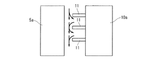
また、壁部10a、10bと熱交換部5aとの間の通気抵抗は、壁部10a、10bにリブ11を設けることで、リブ11を設けない場合に比べて大きくなる。ここで、例えば、図6に示すように、壁部10aと熱交換部5aとの間の吸気の流れ(図6中の矢印を参照)を遮るようにリブ11が設定されている場合には、より効果的に壁部10aと熱交換部5aとの間の通気抵抗を大きくすることができる。これは、リブ11の先端と熱交換部5aとの間隙を通過する際の吸気流速の上昇、リブ11の位置で吸気の流路が縮小することにより生じるエネルギー損失及びリブ11通過後に吸気の流路が拡大することにより生じるエネルギー損失、によって通気抵抗が増加するからである。なお、図6においては、壁部10aと熱交換部5aとの間の吸気の流れに対してリブ11が直交するように設定されており、壁部10aと熱交換部5aとの間の通気抵抗を大きくする上では、リブ11が壁部10aと熱交換部5aとの間の吸気の流れに対して直交していない場合よりも有利となっている。
Moreover, the ventilation resistance between
コレクタ部2は、気筒列方向に沿って細長く、また吸気導入口2aが気筒列方向の一端側に位置した構成となっているので、インタークーラ収容部6内を流れる吸気は、吸気導入口2aから導入された吸気流れの慣性により、吸気導入口2aに近い側(気筒列方向の一端側)に比べ、吸気導入口2aから遠い側(気筒列方向の他端側)により多く流れる傾向がある。従って、インタークーラ5の熱交換部5aと壁部10bとの隙間には、インタークーラ5の熱交換部5aと壁部10aとの隙間よりもより多くの吸気が流れ込み易くなる。よって、熱交換部5aと壁部10bとの隙間を小さく管理することが重要となるため、本実施例では、壁部10bに相対的に多くのリブ11を設定している。なお、壁部10bよりも吸気導入口2aに近接している壁部10aは、成形上肉厚が相対的に厚く設定され易く、リブ11の本数を増やしても熱収縮時等の寸法精度管理が難しくなるため、この点からも壁部10a、10bにそれぞれ複数のリブ11を設ける場合には、吸気導入口2aから遠い側の壁部10bに設けるリブ11の本数を、吸気導入口2aから近い側の壁部10aに設けるリブ11の本数よりも多くすることが望ましい。
Since the
Claims (4)
上記インタークーラ収容部は、気筒列方向に沿って細長い直方体形状を呈し、上記吸気マニホールドの外壁面に開口するとともに、気筒列方向の一端側が上記吸気マニホールドの吸気導入口に近接するように設定され、
上記インタークーラ収容部を構成する壁部のうち、気筒列方向の一端側及び他端側に位置する壁部の内壁面には、上記インタークーラと干渉しないように上記インタークーラ収容部の内側に向かって突出するリブが形成され、
上記インタークーラ収容部内における上記インタークーラと当該インタークーラ収容部との間隙は、上記インタークーラと上記リブの先端との間隙を最小値として該インタークーラ収容部と該インタークーラとが干渉することがない範囲で最小となるように設定されている吸気マニホールド。In a resin intake manifold having an intercooler accommodating portion in which the intercooler is accommodated,
The intercooler housing portion has an elongated rectangular parallelepiped shape along the cylinder row direction, is open to the outer wall surface of the intake manifold, and is set so that one end side in the cylinder row direction is close to the intake inlet of the intake manifold. ,
Of the wall portions constituting the intercooler accommodating portion, the inner wall surfaces of the wall portions located on one end side and the other end side in the cylinder row direction are arranged inside the intercooler accommodating portion so as not to interfere with the intercooler. Ribs projecting toward the
The gap between the intercooler and the intercooler accommodating part in the intercooler accommodating part may interfere with the intercooler accommodating part and the intercooler with the gap between the intercooler and the tip of the rib as a minimum value. Intake manifold that is set to be the smallest in a range.
上記インタークーラ収容部は、上記コレクタ部に形成されている請求項1または2に記載の吸気マニホールド。The intake manifold includes a collector portion and a branch passage portion formed with a plurality of branch passages for distributing intake air from the collector portion to each cylinder,
The intake manifold according to claim 1 or 2, wherein the intercooler accommodating portion is formed in the collector portion.
Priority Applications (1)
| Application Number | Priority Date | Filing Date | Title |
|---|---|---|---|
| JP2014525844A JP5866011B2 (en) | 2012-07-18 | 2013-07-17 | Intake manifold |
Applications Claiming Priority (4)
| Application Number | Priority Date | Filing Date | Title |
|---|---|---|---|
| JP2012159212 | 2012-07-18 | ||
| JP2012159212 | 2012-07-18 | ||
| PCT/JP2013/069390 WO2014014019A1 (en) | 2012-07-18 | 2013-07-17 | Air intake manifold |
| JP2014525844A JP5866011B2 (en) | 2012-07-18 | 2013-07-17 | Intake manifold |
Publications (2)
| Publication Number | Publication Date |
|---|---|
| JP5866011B2 true JP5866011B2 (en) | 2016-02-17 |
| JPWO2014014019A1 JPWO2014014019A1 (en) | 2016-07-07 |
Family
ID=49948844
Family Applications (1)
| Application Number | Title | Priority Date | Filing Date |
|---|---|---|---|
| JP2014525844A Active JP5866011B2 (en) | 2012-07-18 | 2013-07-17 | Intake manifold |
Country Status (5)
| Country | Link |
|---|---|
| US (1) | US10422307B2 (en) |
| EP (1) | EP2876292A4 (en) |
| JP (1) | JP5866011B2 (en) |
| CN (1) | CN104428524B (en) |
| WO (1) | WO2014014019A1 (en) |
Cited By (1)
| Publication number | Priority date | Publication date | Assignee | Title |
|---|---|---|---|---|
| JP2013147952A (en) * | 2012-01-17 | 2013-08-01 | Mazda Motor Corp | Intake device of engine |
Families Citing this family (9)
| Publication number | Priority date | Publication date | Assignee | Title |
|---|---|---|---|---|
| JP6409560B2 (en) * | 2014-12-24 | 2018-10-24 | 三菱自動車工業株式会社 | Engine intake structure |
| JP2016169618A (en) * | 2015-03-11 | 2016-09-23 | 株式会社ケーヒン | Intake manifold device |
| JP6550969B2 (en) * | 2015-06-30 | 2019-07-31 | 三菱自動車工業株式会社 | Engine intake supply structure |
| JP6767900B2 (en) * | 2017-03-02 | 2020-10-14 | 株式会社ケーヒン | Intake manifold device |
| US10801448B2 (en) | 2018-01-15 | 2020-10-13 | Ford Global Technologies, Llc | Integral intake manifold |
| US10815945B2 (en) * | 2018-01-15 | 2020-10-27 | Ford Global Technologies, Llc | Integral intake manifold |
| JP7139958B2 (en) * | 2019-01-10 | 2022-09-21 | トヨタ紡織株式会社 | Intake manifold |
| JP7227850B2 (en) * | 2019-05-22 | 2023-02-22 | タイガースポリマー株式会社 | rectifier structure |
| JP7294159B2 (en) * | 2020-01-20 | 2023-06-20 | マツダ株式会社 | engine intake system |
Citations (4)
| Publication number | Priority date | Publication date | Assignee | Title |
|---|---|---|---|---|
| JPS58148221U (en) * | 1982-03-31 | 1983-10-05 | 日野自動車株式会社 | Intercooler for turbocharger |
| JPS6076775U (en) * | 1983-10-25 | 1985-05-29 | ヤンマーディーゼル株式会社 | intercooler |
| JP2010127143A (en) * | 2008-11-26 | 2010-06-10 | Calsonic Kansei Corp | Charge air cooler |
| JP2012102667A (en) * | 2010-11-10 | 2012-05-31 | Denso Corp | Intake air cooling device |
Family Cites Families (8)
| Publication number | Priority date | Publication date | Assignee | Title |
|---|---|---|---|---|
| JPS58148221A (en) * | 1982-02-25 | 1983-09-03 | Honda Motor Co Ltd | Cooling water passage device of water-cooled v-engine for autobicycle |
| US4476842A (en) * | 1982-09-20 | 1984-10-16 | Allis-Chalmers Corporation | Intercooler damper support |
| DE19902504B4 (en) * | 1999-01-22 | 2005-09-22 | Behr Gmbh & Co. Kg | Heat exchanger, in particular intercooler |
| DE102009025282A1 (en) * | 2009-06-15 | 2010-12-16 | Behr Gmbh & Co. Kg | Intake manifold with integrated intercooler |
| DE102009050258B3 (en) * | 2009-10-21 | 2010-11-18 | Mann + Hummel Gmbh | Intake manifold for internal combustion engine, particularly for motor vehicle, has coolant intercooler arranged at opposite end of cooling fluid boxes |
| CN201835953U (en) * | 2010-10-13 | 2011-05-18 | 哈尔滨东安汽车动力股份有限公司 | Plastic air inlet manifold |
| JP2012082770A (en) | 2010-10-13 | 2012-04-26 | Denso Corp | Engine intake device |
| JP5664586B2 (en) * | 2012-04-05 | 2015-02-04 | 株式会社デンソー | Intake system for internal combustion engine |
-
2013
- 2013-07-17 EP EP13819474.1A patent/EP2876292A4/en not_active Withdrawn
- 2013-07-17 WO PCT/JP2013/069390 patent/WO2014014019A1/en active Application Filing
- 2013-07-17 US US14/414,790 patent/US10422307B2/en active Active
- 2013-07-17 JP JP2014525844A patent/JP5866011B2/en active Active
- 2013-07-17 CN CN201380036762.0A patent/CN104428524B/en active Active
Patent Citations (4)
| Publication number | Priority date | Publication date | Assignee | Title |
|---|---|---|---|---|
| JPS58148221U (en) * | 1982-03-31 | 1983-10-05 | 日野自動車株式会社 | Intercooler for turbocharger |
| JPS6076775U (en) * | 1983-10-25 | 1985-05-29 | ヤンマーディーゼル株式会社 | intercooler |
| JP2010127143A (en) * | 2008-11-26 | 2010-06-10 | Calsonic Kansei Corp | Charge air cooler |
| JP2012102667A (en) * | 2010-11-10 | 2012-05-31 | Denso Corp | Intake air cooling device |
Cited By (1)
| Publication number | Priority date | Publication date | Assignee | Title |
|---|---|---|---|---|
| JP2013147952A (en) * | 2012-01-17 | 2013-08-01 | Mazda Motor Corp | Intake device of engine |
Also Published As
| Publication number | Publication date |
|---|---|
| CN104428524A (en) | 2015-03-18 |
| WO2014014019A1 (en) | 2014-01-23 |
| EP2876292A1 (en) | 2015-05-27 |
| US10422307B2 (en) | 2019-09-24 |
| CN104428524B (en) | 2017-03-08 |
| EP2876292A4 (en) | 2015-06-17 |
| JPWO2014014019A1 (en) | 2016-07-07 |
| US20150176549A1 (en) | 2015-06-25 |
Similar Documents
| Publication | Publication Date | Title |
|---|---|---|
| JP5866011B2 (en) | Intake manifold | |
| US10619946B2 (en) | Heat exchanger for cooling a flow of compressed air using a liquid coolant | |
| JP4446989B2 (en) | Cylinder block and internal combustion engine | |
| US20170122678A1 (en) | Heat exchanger | |
| US20140246185A1 (en) | Heat Exchanger With Stacked Plates | |
| JP2010223508A (en) | Intercooler of engine for vehicle | |
| JP2017106668A (en) | Heat exchanger | |
| JP2013011175A (en) | Seal structure of intake manifold | |
| CN105308408A (en) | Heat exchanger, in particular a supercharging air cooler | |
| JP2012097675A (en) | Intake system of internal combustion engine | |
| CN103608577A (en) | Intake housing including a heat exchanger | |
| US20140166253A1 (en) | Heat Exchanger, In Particular For A Motor Vehicle, And Corresponding Air Intake Device | |
| JP2019044644A (en) | Intake system | |
| JP2014500941A (en) | Heat exchanger and associated method of forming a flow perturbant | |
| US11066981B2 (en) | Air distributor and vehicle comprising this air distributor | |
| US9766023B2 (en) | Heat exchanger in a housing | |
| JP2010112201A (en) | U-turn type egr cooler | |
| JP2016070655A (en) | Heat exchanger | |
| WO2017018431A1 (en) | Mounting structure for water-cooled air coolers | |
| JP6481275B2 (en) | Corrugated fin heat exchanger | |
| JP2014043772A (en) | Cylinder head | |
| US11156406B2 (en) | Heat exchanger | |
| JP4396306B2 (en) | Engine exhaust gas recirculation system | |
| KR102605321B1 (en) | Heat exchanger | |
| JP7349821B2 (en) | Heat exchanger |
Legal Events
| Date | Code | Title | Description |
|---|---|---|---|
| TRDD | Decision of grant or rejection written | ||
| A01 | Written decision to grant a patent or to grant a registration (utility model) |
Free format text: JAPANESE INTERMEDIATE CODE: A01 Effective date: 20151208 |
|
| A61 | First payment of annual fees (during grant procedure) |
Free format text: JAPANESE INTERMEDIATE CODE: A61 Effective date: 20151228 |
|
| R150 | Certificate of patent or registration of utility model |
Ref document number: 5866011 Country of ref document: JP Free format text: JAPANESE INTERMEDIATE CODE: R150 |
|
| S533 | Written request for registration of change of name |
Free format text: JAPANESE INTERMEDIATE CODE: R313533 |
|
| R350 | Written notification of registration of transfer |
Free format text: JAPANESE INTERMEDIATE CODE: R350 |