JP5865922B2 - Method and apparatus for actuating an actuator in an automotive motor system - Google Patents
Method and apparatus for actuating an actuator in an automotive motor system Download PDFInfo
- Publication number
- JP5865922B2 JP5865922B2 JP2013555808A JP2013555808A JP5865922B2 JP 5865922 B2 JP5865922 B2 JP 5865922B2 JP 2013555808 A JP2013555808 A JP 2013555808A JP 2013555808 A JP2013555808 A JP 2013555808A JP 5865922 B2 JP5865922 B2 JP 5865922B2
- Authority
- JP
- Japan
- Prior art keywords
- actuator
- positioning
- space vector
- blocked
- actuator system
- Prior art date
- Legal status (The legal status is an assumption and is not a legal conclusion. Google has not performed a legal analysis and makes no representation as to the accuracy of the status listed.)
- Expired - Fee Related
Links
Images

Classifications
-
- F—MECHANICAL ENGINEERING; LIGHTING; HEATING; WEAPONS; BLASTING
- F02—COMBUSTION ENGINES; HOT-GAS OR COMBUSTION-PRODUCT ENGINE PLANTS
- F02D—CONTROLLING COMBUSTION ENGINES
- F02D11/00—Arrangements for, or adaptations to, non-automatic engine control initiation means, e.g. operator initiated
- F02D11/06—Arrangements for, or adaptations to, non-automatic engine control initiation means, e.g. operator initiated characterised by non-mechanical control linkages, e.g. fluid control linkages or by control linkages with power drive or assistance
- F02D11/10—Arrangements for, or adaptations to, non-automatic engine control initiation means, e.g. operator initiated characterised by non-mechanical control linkages, e.g. fluid control linkages or by control linkages with power drive or assistance of the electric type
- F02D11/107—Safety-related aspects
-
- F—MECHANICAL ENGINEERING; LIGHTING; HEATING; WEAPONS; BLASTING
- F15—FLUID-PRESSURE ACTUATORS; HYDRAULICS OR PNEUMATICS IN GENERAL
- F15B—SYSTEMS ACTING BY MEANS OF FLUIDS IN GENERAL; FLUID-PRESSURE ACTUATORS, e.g. SERVOMOTORS; DETAILS OF FLUID-PRESSURE SYSTEMS, NOT OTHERWISE PROVIDED FOR
- F15B11/00—Servomotor systems without provision for follow-up action; Circuits therefor
- F15B11/08—Servomotor systems without provision for follow-up action; Circuits therefor with only one servomotor
-
- F—MECHANICAL ENGINEERING; LIGHTING; HEATING; WEAPONS; BLASTING
- F02—COMBUSTION ENGINES; HOT-GAS OR COMBUSTION-PRODUCT ENGINE PLANTS
- F02D—CONTROLLING COMBUSTION ENGINES
- F02D41/00—Electrical control of supply of combustible mixture or its constituents
- F02D41/02—Circuit arrangements for generating control signals
- F02D41/04—Introducing corrections for particular operating conditions
- F02D41/06—Introducing corrections for particular operating conditions for engine starting or warming up
- F02D41/062—Introducing corrections for particular operating conditions for engine starting or warming up for starting
-
- F—MECHANICAL ENGINEERING; LIGHTING; HEATING; WEAPONS; BLASTING
- F02—COMBUSTION ENGINES; HOT-GAS OR COMBUSTION-PRODUCT ENGINE PLANTS
- F02D—CONTROLLING COMBUSTION ENGINES
- F02D11/00—Arrangements for, or adaptations to, non-automatic engine control initiation means, e.g. operator initiated
- F02D11/06—Arrangements for, or adaptations to, non-automatic engine control initiation means, e.g. operator initiated characterised by non-mechanical control linkages, e.g. fluid control linkages or by control linkages with power drive or assistance
- F02D11/10—Arrangements for, or adaptations to, non-automatic engine control initiation means, e.g. operator initiated characterised by non-mechanical control linkages, e.g. fluid control linkages or by control linkages with power drive or assistance of the electric type
- F02D2011/108—Arrangements for, or adaptations to, non-automatic engine control initiation means, e.g. operator initiated characterised by non-mechanical control linkages, e.g. fluid control linkages or by control linkages with power drive or assistance of the electric type with means for detecting or resolving a stuck throttle, e.g. when being frozen in a position
-
- F—MECHANICAL ENGINEERING; LIGHTING; HEATING; WEAPONS; BLASTING
- F02—COMBUSTION ENGINES; HOT-GAS OR COMBUSTION-PRODUCT ENGINE PLANTS
- F02D—CONTROLLING COMBUSTION ENGINES
- F02D2200/00—Input parameters for engine control
- F02D2200/02—Input parameters for engine control the parameters being related to the engine
- F02D2200/04—Engine intake system parameters
- F02D2200/0404—Throttle position
-
- F—MECHANICAL ENGINEERING; LIGHTING; HEATING; WEAPONS; BLASTING
- F02—COMBUSTION ENGINES; HOT-GAS OR COMBUSTION-PRODUCT ENGINE PLANTS
- F02D—CONTROLLING COMBUSTION ENGINES
- F02D41/00—Electrical control of supply of combustible mixture or its constituents
- F02D41/02—Circuit arrangements for generating control signals
- F02D41/04—Introducing corrections for particular operating conditions
- F02D41/042—Introducing corrections for particular operating conditions for stopping the engine
-
- F—MECHANICAL ENGINEERING; LIGHTING; HEATING; WEAPONS; BLASTING
- F02—COMBUSTION ENGINES; HOT-GAS OR COMBUSTION-PRODUCT ENGINE PLANTS
- F02D—CONTROLLING COMBUSTION ENGINES
- F02D9/00—Controlling engines by throttling air or fuel-and-air induction conduits or exhaust conduits
- F02D9/08—Throttle valves specially adapted therefor; Arrangements of such valves in conduits
- F02D9/10—Throttle valves specially adapted therefor; Arrangements of such valves in conduits having pivotally-mounted flaps
- F02D9/1035—Details of the valve housing
- F02D9/105—Details of the valve housing having a throttle position sensor
Description
本発明は、電子整流された駆動部を備えたポジショニングアクチュエータに関する。これは、起動中にブロッキングが生じ得る環境において用いられる。殊に本発明は、このブロッキングを解除するための方法および電子整流された駆動部の回転子の回転子位置を求めるための方法に関する。これによって、最大トルクが得られる。 The present invention relates to a positioning actuator including an electronically rectified drive unit. This is used in environments where blocking can occur during startup. In particular, the invention relates to a method for releasing this blocking and a method for determining the rotor position of the rotor of the electronically commutated drive. Thereby, the maximum torque is obtained.
従来技術
ポジショニングアクチュエータ用の駆動部は例えば、電子整流されたモータを有する。電子整流されたモータ、例えば、同期モータは、永久磁石を備えた回転子を有する。これは固定子に対して動く。固定子には複数の固定子コイルが設けられている。ここで固定子コイルに回転子位置に従って通電することによって、モータ磁界が形成される。このモータ磁界は、永久磁石によって形成された励起磁界と協働して、所望の駆動力が回転子に作用する。最大の効率を得るために、モータ磁界が励起磁界に対して、電気位置角の90°の進みを有していることが望ましい。従って、回転子位置に依存した、固定子コイルの通電のために、固定子の位置に関する情報が必要となる。このような回転子位置は、センサを介して検出される、またはいわゆるセンサを用いない位置検出方法によって求められる。
Prior Art A drive unit for a positioning actuator has, for example, an electronically rectified motor. Electronically commutated motors, such as synchronous motors, have a rotor with permanent magnets. This moves relative to the stator. The stator is provided with a plurality of stator coils. Here, by energizing the stator coil according to the rotor position, a motor magnetic field is formed. The motor magnetic field cooperates with the excitation magnetic field formed by the permanent magnet, and a desired driving force acts on the rotor. In order to obtain maximum efficiency, it is desirable for the motor magnetic field to have an electrical position angle advance of 90 ° relative to the excitation magnetic field. Therefore, in order to energize the stator coil depending on the rotor position, information on the position of the stator is required. Such a rotor position is detected by a sensor or is determined by a position detection method that does not use a so-called sensor.
回転子の回転子位置および所望の運動方向に基づいて、適切な制御ユニットによって、相応の整流パターンが設定可能である。これは、必要な駆動力ないしは必要なトルクを供給するために、固定子コイルがどのように駆動制御されるべきかを決める。 Based on the rotor position of the rotor and the desired direction of movement, a corresponding commutation pattern can be set by an appropriate control unit. This determines how the stator coil should be driven and controlled to provide the necessary driving force or torque.
簡易な同期モータの場合には、回転子位置の検出は、内部の位置センサを介して行われる;しかし、この位置センサをアクチュエータの外部に配置すること、ないしは、そこに配置されている位置センサを付加的に、回転子位置を求めるために用いることも可能である。これによって、同期モータに対するコストも、同期モータと制御機器との間の配線のためのコストも低減することができる。 In the case of a simple synchronous motor, the detection of the rotor position takes place via an internal position sensor; however, this position sensor can be arranged outside the actuator, or a position sensor arranged there. Can also be used to determine the rotor position. Thereby, the cost for the synchronous motor and the cost for wiring between the synchronous motor and the control device can be reduced.
同期モータの駆動制御は、種々の整流様式によって行われる。ここで、最大駆動モーメントを得るために、固定子コイルによって形成されたモータ磁界ができるだけ、回転子の永久磁石によって形成された励起磁界に対して90°運動方向に進んで調整される。90°のこの進みの相違によって、駆動力ないしは駆動モーメントの減少が生じる。常に、可能な最大トルクで駆動制御を行うために、正確な回転子位置情報が必要である。例えばセンサトレランスと解像の不正確さによって生起され得る、実際の回転子位置と測定された回転子位置との間の相違によって、部分的に、効率が格段に低減されてしまう。 The drive control of the synchronous motor is performed by various commutation modes. Here, in order to obtain the maximum drive moment, the motor magnetic field formed by the stator coils is adjusted as far as possible in the direction of movement by 90 ° with respect to the excitation magnetic field formed by the permanent magnets of the rotor. This advance difference of 90 ° results in a reduction in driving force or driving moment. Accurate rotor position information is always required to control the drive with the maximum possible torque. The difference between the actual rotor position and the measured rotor position, which can be caused by sensor tolerance and resolution inaccuracy, for example, results in a significant reduction in efficiency.
殊に、減速するギヤを介して結合されているアクチュエータで位置情報検出する、外部位置センサを有するアクチュエータの実施形態では、実際の回転子位置と測定された回転子位置との間の相違がさらに強くなり得る。外部位置センサが設けられ得る例は、例えば、スロットルバルブ調整器である。ここではスロットルバルブの位置の位置フィードバックがいずれにせよ設けられており、これによって、スロットルバルブの正確な位置情報が得られる。スロットルバルブを駆動制御する同期モータの整流のために、スロットルバルブに配置されている位置センサの位置情報を使用することによっても、上述した相違が生じることがあり、これによって、同期センサによって提供される調整モーメントが格段に低減されてしまう。 In particular, in an embodiment of an actuator having an external position sensor that detects position information with an actuator coupled via a decelerating gear, the difference between the actual rotor position and the measured rotor position is further increased. Can be strong. An example where an external position sensor can be provided is, for example, a throttle valve regulator. Here, position feedback of the position of the throttle valve is provided anyway, whereby accurate position information of the throttle valve can be obtained. Using the position information of the position sensor located on the throttle valve for the commutation of the synchronous motor that drives and controls the throttle valve can also cause the above-mentioned differences, which are provided by the synchronous sensor. The adjustment moment is greatly reduced.
モーターシステムが晒され得る温度が極めて低い場合には、凍結が生じる恐れがある。これは、モーターシステムの動作の再稼働時にアクチュエータの運動をブロックしてしまう。このようなブロック状態を解除するために、殊に、基準位置の走行開始または終端位置の走行開始によって回転子位置の再較正を行うために、始動直後に、同期モータの最大の調整モーメントが必要になる。このような最大調整モーメントを提供するために、実際の回転子位置と測定された回転子位置との間の偏差ができるだけ少ないべきである。これによって、調整モーメントができるだけ最大になり得る。しかし、温度に基づいて、位置センサの相応に特徴付けされた温度ドリフトによって、顕著なエラー角度が生じる恐れがあり、これによって、同期モータのトルクが、許容されないほど、弱くなってしまうことがある。場合によっては、このトルク低下によって、凍結したアクチュエータが自身のブロックから開放されず、モーターシステムが動作不能になってしまう。 Freezing can occur if the temperature to which the motor system can be exposed is very low. This blocks the movement of the actuator when the motor system is reactivated. In order to release such a block state, in particular, the maximum adjustment moment of the synchronous motor is required immediately after starting in order to recalibrate the rotor position by starting the driving at the reference position or starting at the end position. become. In order to provide such a maximum adjustment moment, the deviation between the actual rotor position and the measured rotor position should be as small as possible. This can maximize the adjustment moment as much as possible. However, based on temperature, a correspondingly characterized temperature drift of the position sensor can cause a significant error angle, which can cause the torque of the synchronous motor to become unacceptably weak. . In some cases, this reduced torque does not release the frozen actuator from its own block and renders the motor system inoperable.
さらに、位置センサは、アクチュエータで、相対的な位置センサとしてのみ構成されている。従って、調整システムの動作開始時には、回転子の実際の位置は確定されない。また較正のために、通常、アクチュエータを最適に駆動制御するために、アクチュエータが所定の終端ストッパーまで動かされるが、これはアクチュエータのブロック時には不可能であるので、回転子の初期の駆動制御を最大の駆動力で行うことはできない。 Furthermore, the position sensor is an actuator and is configured only as a relative position sensor. Therefore, the actual position of the rotor is not determined at the start of the operation of the adjustment system. For calibration, the actuator is usually moved to a predetermined end stop to optimally control the actuator, but this is not possible when the actuator is blocked, thus maximizing the initial drive control of the rotor. This cannot be done with the driving force.
文献DE4135913A1号は、位置調整装置の制御方法を開示している。ここでは、始動前フェーズで、および/または駆動ユニットまたは車両の停止後に、位置調整装置が、任意の位置から出発して各可能な運動方向に対して、少なくとも一度、少なくとも自身の可能な最大運動領域の大部分にわたって動かされる。従ってこれは少なくとも片側で、自身の通常の駆動運動領域外に導かれる。このようにして、デッドロックが回避される。 Document DE 4135913A1 discloses a method for controlling a position adjusting device. Here, in the pre-start phase and / or after the drive unit or vehicle is stopped, the position adjustment device starts at any position and at least once for each possible movement direction, at least its maximum possible movement Moved over most of the area. It is therefore guided at least on one side out of its normal drive movement area. In this way deadlock is avoided.
文献DE3743309A1は、動かなくなったまたは凍結された、内燃機関の調整部材を識別する方法および装置を開示している。ここでは調整部材は、動かなくなった場合に、揺すってゆるめられる。この揺すりは、例えば、位置調整装置の電気駆動部が反対に駆動制御されることによって行われる。 Document DE 3743309A1 discloses a method and apparatus for identifying a regulating member of an internal combustion engine that has become immobile or frozen. Here, the adjustment member is rocked and loosened when it stops moving. This shaking is performed by, for example, driving and controlling the electric drive unit of the position adjusting device in the opposite direction.
文献DE10017546A1号は、スロットルバルブの位置の実際値と目標値に依存して、スロットルバルブのブロックを識別する方法を開示している。ブロックを識別した後に、スロットルバルブの位置に対する目標値が変えられる。 Document DE 10017546 A1 discloses a method for identifying a block of a throttle valve, depending on the actual value and the target value of the position of the throttle valve. After identifying the block, the target value for the throttle valve position is changed.
文献EP0391930B1号は、内燃機関の動作特性量を調整する方法を開示している。ここで内燃機関の空気供給を調整するアクチュエータのデッドロックが、設定された位置とこの時点での位置との間の差に基づいて識別され、デッドロックが識別されると、アクチュエータは周期的な揺すり運動を開始し、これによってこのデッドロックが解除される。 Document EP 0391930 B1 discloses a method for adjusting the operating characteristic quantity of an internal combustion engine. Here, the deadlock of the actuator that regulates the air supply of the internal combustion engine is identified based on the difference between the set position and the current position, and once the deadlock is identified, the actuator A rocking motion is started, and this deadlock is released.
本発明の課題は、ポジショニングアクチュエータのアクチュエータのブロックを解除する、ないしはモーターシステムの起動後に最大の調整モーメントで駆動制御する、改善された方法を提供することである。 It is an object of the present invention to provide an improved method of unblocking the actuator of a positioning actuator or driving and controlling with a maximum adjustment moment after the motor system is started.
発明の開示
上述の課題は、請求項1のポジショニングアクチュエータを駆動制御する方法によって、並びに、並行する独立請求項に記載された装置およびポジショニングアクチュエータシステムによって解決される。
DISCLOSURE OF THE INVENTION The above-mentioned problems are solved by the method for driving and controlling the positioning actuator of claim 1 and by the apparatus and positioning actuator system described in the parallel independent claims.
さらなる有利な構成は従属請求項に記載されている。 Further advantageous configurations are described in the dependent claims.
第1の態様では、アクチュエータを駆動する、電子整流されたアクチュエータ駆動部を有するポジショニングアクチュエータシステムの動作方法が設定される。この方法は以下のステップを有している:
・アクチュエータないしはアクチュエータ駆動部の回転子の、ポジショニングアクチュエータシステムの停止前に最後に検出された位置情報を、基準位置として不揮発的に記憶するステップ
・ポジショニングアクチュエータシステムをオンにした時に、基準位置を呼び出し、基準位置に依存している空間ベクトル(Raumzeiger)に従ってアクチュエータ駆動部に通電することによってアクチュエータ駆動部を駆動制御するステップ
とを有している。
In the first aspect, a method of operating a positioning actuator system having an electronically rectified actuator driving unit that drives the actuator is set. This method has the following steps:
-The position information of the actuator or the rotor of the actuator drive that was detected last before stopping the positioning actuator system is stored in a nonvolatile manner as a reference position.-The reference position is called when the positioning actuator system is turned on. And driving the actuator drive unit by energizing the actuator drive unit according to a space vector (Raumzeiger) depending on the reference position.
上述した方法の着想は、ポジショニングアクチュエータシステムの停止後に、アクチュエータが自身の静止位置を取るや否や、例えば内燃機関停止時のモータ制御の後走行フェーズにおいて、アクチュエータが取った位置が検出され、制御機器内に基準位置として不揮発的に記憶される、ということである。ポジショニングアクチュエータシステムの再始動時に、位置検出器はこの基準位置によって較正される、または、アライメントされる。従ってポジショニングアクチュエータは、適切な空間ベクトルに従って通電される。これは、電子整流されたアクチュエータ駆動部が、直接的に回転子位置に依存している励起磁界の位置に対して実質的に垂直なモータ磁界を形成するように、アクチュエータ駆動部が駆動制御されることを意味している。 The idea of the method described above is that as soon as the actuator takes its own rest position after the positioning actuator system is stopped, the position taken by the actuator is detected in the driving phase after motor control when the internal combustion engine is stopped, for example. It is stored in a nonvolatile manner as a reference position. Upon restart of the positioning actuator system, the position detector is calibrated or aligned with this reference position. The positioning actuator is therefore energized according to the appropriate space vector. This is because the actuator drive is driven and controlled so that the electronically rectified actuator drive forms a motor magnetic field that is substantially perpendicular to the position of the excitation magnetic field that is directly dependent on the rotor position. It means that.
さらに、ポジショニングアクチュエータシステムのオン後に、アクチュエータがブロックされているか否かが確認される。ここで、アクチュエータがブロックされていることが確認されると、アクチュエータ駆動部が、空間ベクトルに従って通電される。これは、基準位置に対応する空間ベクトルの周りで変化する。殊に、アクチュエータがブロックされていることが確認されると、電気的な回転子位置の180°ぶんだけ変化する空間ベクトルによってアクチュエータ駆動部が駆動制御されるようにすることができる。 Furthermore, after the positioning actuator system is turned on, it is checked whether the actuator is blocked. Here, when it is confirmed that the actuator is blocked, the actuator driving unit is energized according to the space vector. This varies around the space vector corresponding to the reference position. In particular, when it is confirmed that the actuator is blocked, the actuator driving unit can be driven and controlled by a space vector that changes by 180 ° of the electrical rotor position.
さらに、ポジショニングアクチュエータシステムのオン後に、アクチュエータがブロックされているか否かが確認され、アクチュエータがブロックされていることが確認されると、アクチュエータ駆動部が回転する空間ベクトルに従って通電される。 Furthermore, after the positioning actuator system is turned on, it is confirmed whether or not the actuator is blocked. If it is confirmed that the actuator is blocked, the actuator drive unit is energized according to the rotating space vector.
ここでさらに、回転する空間ベクトルの回転周波数が所定の回転周波数に対応するようにすることができる。ここでポジショニングアクチュエータシステムは共振を有している。従って、調整力が、アクチュエータ駆動部の最大調整力と比べて大きくなる。 Here, furthermore, the rotation frequency of the rotating space vector can correspond to a predetermined rotation frequency. Here, the positioning actuator system has resonance. Therefore, the adjustment force becomes larger than the maximum adjustment force of the actuator driving unit.
択一的に、回転する空間ベクトルの回転周波数を変化させることができる。 Alternatively, the rotational frequency of the rotating space vector can be changed.
別の態様では、ポジショニングアクチュエータシステムの動作装置が設けられる。このポジショニングアクチュエータシステムは、アクチュエータを駆動する電子整流されたアクチュエータ駆動部を有している。ここでこの装置は、
・ポジショニングアクチュエータシステムの停止前の、アクチュエータないしはアクチュエータ駆動部の回転子の最後に検出された位置情報を、基準位置として不揮発的に記憶する、および
・ポジショニングアクチュエータシステムのオン時に、基準位置を呼び出し、基準位置に依存している空間ベクトルに従ってアクチュエータ駆動部に通電することによってアクチュエータ駆動部を駆動制御する
ように構成されている。
In another aspect, an operating device for a positioning actuator system is provided. This positioning actuator system has an electronically rectified actuator drive that drives the actuator. Here this device is
The non-volatile storage of the position information detected at the end of the actuator or the rotor of the actuator drive unit before the positioning actuator system is stopped as a reference position, and the reference position is called when the positioning actuator system is turned on, The actuator drive unit is driven and controlled by energizing the actuator drive unit according to a space vector that depends on the reference position.
別の態様では、ポジショニングアクチュエータシステムが設けられる。このポジショニングアクチュエータシステムは:
・アクチュエータと、
・このアクチュエータを駆動する、電子整流されたアクチュエータ駆動部と、
・ポジショニングアクチュエータシステムの停止前の、アクチュエータの最後に検出された位置情報を基準位置として記憶するために不揮発性メモリと接続されている制御機器とを有しており、
ここでこの制御機器は、ポジショニングアクチュエータシステムのオン時にこの基準位置を呼び出し、この基準位置に依存している空間ベクトルに従ってアクチュエータ駆動部に通電することによってアクチュエータ駆動部を駆動制御するように構成されている。
In another aspect, a positioning actuator system is provided. This positioning actuator system is:
An actuator,
An electronically rectified actuator drive that drives this actuator;
A control device connected to a non-volatile memory to store the position information detected at the end of the actuator before the positioning actuator system is stopped as a reference position;
Here, the control device is configured to call the reference position when the positioning actuator system is turned on and to drive and control the actuator drive unit by energizing the actuator drive unit according to a space vector that depends on the reference position. Yes.
別の態様では、コンピュータプログラムが設定されている。このコンピュータプログラムは、データ処理ユニット上での実行時に、上述した方法を実施するプログラムコードを含んでいる。 In another aspect, a computer program is set. This computer program includes program code that, when executed on the data processing unit, implements the method described above.
本発明の有利な実施形態を以降で、添付の図面に基づいて詳細に説明する: Advantageous embodiments of the invention will be described in detail hereinafter with reference to the accompanying drawings:
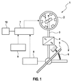
図1は、電子整流された同期モータとして形成されているアクチュエータモータ2を備えたポジショニングアクチュエータシステム1の概略図を示している。同期モータ2は、内側回転子モータとして形成されており、その駆動シャフト3は伝動装置4を介してアクチュエータ5、例えばスロットルバルブ等と結合されている。スロットルバルブ5には、戻しばね6によって戻し力が加えられ、これによって、スロットルバルブ5の無通電状態において、スロットルバルブは特定の調整領域、例えば、終端ストッパーにまたは終端ストッパー近傍に配置される。
FIG. 1 shows a schematic view of a positioning actuator system 1 with an actuator motor 2 formed as an electronically commutated synchronous motor. The synchronous motor 2 is formed as an inner rotor motor, and its drive shaft 3 is coupled to an
同期モータ2は、制御機器7を介して駆動制御され、これによって、伝動装置4を介してアクチュエータ5に作用する特定の調整モーメントが提供される。通常、制御機器7内には、位置調整部が実装される。これは、制御機器7内に組み込まれている位置調整回路によって、アクチュエータ5の所望の目標位置を調整する。このために、アクチュエータ5は位置センサ8と結合されている。この位置センサは、アクチュエータ5の位置に関する情報を制御機器7に伝達する。アクチュエータ5の目標位置に関する、制御機器7内に準備された情報と、位置センサ8によって提供されたアクチュエータ5の実際位置に依存して、特定の調整モーメントが伝動装置4を介してアクチュエータ5に作用するように、同期モータ2が駆動制御される。アクチュエータ5が調整されるべき角度は制御機器7内で、アクセルペダル9によって提供されるアクセルペダル位置に基づいて、すなわち、運転手の設定に基づいて、さらに、場合によっては別のシステム量に基づいて求められ、位置調整回路に対する目標位置として設定される。制御機器7はさらに、ポジショニングアクチュエータシステム1が停止された場合でも、パラメータ、例えば修正パラメータ等を継続して記憶するために、不揮発性メモリ10と接続されている。
The synchronous motor 2 is driven and controlled via the
温度が極めて低く、かつポジショニングアクチュエータシステム1が停止状態にある場合、例えば内燃機関がオフされている場合には、アクチュエータ5が凍結することがあり得る。この凍結は場合によっては、アクチュエータ5の動きをブロックしてしまう。従って、このブロック状態を内燃機関始動直後に解く必要がある。これは例えば、同期モータ2によって最大トルクを提供することによって実現される。この理由から、既に内燃機関の始動中に、同期モータ2の回転子位置を正確に知ることが必要となる。これによって、回転子位置の不正確な決定による調整モーメントの低減ができるだけ僅かになる。
If the temperature is very low and the positioning actuator system 1 is in a stopped state, for example when the internal combustion engine is turned off, the
しかし、温度が低いので、位置センサ8の相応の特徴を有する温度ドリフトの際には、不正確にしか回転子位置を推測することができない。これによって、求められた回転子位置と実際の回転子位置との間に顕著な差が生じてしまう。 However, since the temperature is low, the rotor position can only be estimated inaccurately during a temperature drift with corresponding features of the position sensor 8. This creates a significant difference between the determined rotor position and the actual rotor position.
多くのポジショニングアクチュエータシステムは、オフ状態からの起動前にまずは較正されなければならない、相対的な位置センサを有している。これは位置センサが、同期モータの回転子の単に制御されている動作において、既知の位置まで動かされることによって行われる。アクチュエータの生じ得るブロック時には、この較正を行うことができないので、この位置センサによって、実際の回転子位置に関する情報は求められない。 Many positioning actuator systems have relative position sensors that must first be calibrated before activation from the off state. This is done by the position sensor being moved to a known position in the controlled operation of the synchronous motor rotor. Since this calibration cannot be performed during the possible block of the actuator, no information on the actual rotor position is determined by this position sensor.
実際の回転子位置に関する情報が存在しない場合には、同期モータ2の回転子は最適に駆動制御されない。すなわち同期モータ2は、アクチュエータ5の場合によって生じ得るブロックを解除するために最大駆動モーメントを提供することができない。
When there is no information regarding the actual rotor position, the rotor of the synchronous motor 2 is not optimally driven and controlled. That is, the synchronous motor 2 cannot provide a maximum driving moment to release a block that may occur in the case of the
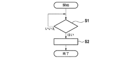
図2aおよび2bには、フローチャートが示されている。これによって、モータ始動フェーズの間に既に、最大トルクをアクチュエータ5に与えることができる。
A flow chart is shown in FIGS. 2a and 2b. This allows the maximum torque to be applied to the
図2aのフローチャートは、内燃機関停止後に、後走行フェーズ中に実施される方法の経過を示している。ここでは、アクチュエータ5が監視される(ステップS1)。例えば、同期モータ2がもはや通電されていない時に確認され得るアクチュエータ5の停止状態において(選択肢:はい)、基準位置である、位置センサ8によって最後に検出された、アクチュエータ5の位置に関する情報が、制御機器7によって不揮発性メモリ10内に格納される(ステップS2)。択一的に、アクチュエータの最後に検出された位置から生じる基準回転子位置が、不揮発性メモリ10内に格納される。
The flowchart of FIG. 2a shows the course of the method carried out during the afterrun phase after the internal combustion engine has stopped. Here, the
図2bのフローチャートは、内燃機関のオン後に実施される方法の経過を示している。内燃機関の始動およびこれと同時のポジショニングアクチュエータシステム1のオンの際に、記憶されていたこの位置情報が不揮発性メモリ10から基準として呼び出され(ステップS3)、ここで位置センサ8によって供給された位置情報が、格納されている基準位置情報ないしは基準回転子位置を用いて修正され(ステップ4)、これによって、位置センサ8の温度ドリフトが取り除かれる。相対的な位置センサ8の使用時には、基準位置情報ないしは基準回転子位置を用いて、初期の較正(初期化)が行われる。
The flowchart of FIG. 2b shows the course of the method that is carried out after the internal combustion engine is turned on. When the internal combustion engine is started and the positioning actuator system 1 is turned on at the same time, this stored position information is retrieved from the
次に(ステップS5)、ブロック検出が実施される。これは、制御機器7が同期モータ2を、アクチュエータ5の位置を変える調整モーメントが提供されるように駆動制御することによって行われる。ステップS6において、このような位置変化が識別されると(選択肢:はい)、スロットルバルブ5はブロックされておらず、ポジショニングアクチュエータシステムは運転手設定等に基づいて、内燃機関の慣例の動作のために位置調整を行う。
Next (step S5), block detection is performed. This is performed by the
ステップS6において、アクチュエータS5のブロックが検出されると(選択肢:いいえ)、同期モータ2は御機器7によって次のように駆動制御される(ステップS7)。すなわち空間ベクトルが、記憶された基準位置に対応する空間ベクトルの周りで変化し、これによって、最大の提供可能な調整モーメントを中心に変動する調整モーメントが生じるように駆動制御される。従って、変化する調整モーメントによって、アクチュエータ5をブロック状態から開放することが試みられる。
When the block of the actuator S5 is detected in step S6 (option: No), the synchronous motor 2 is driven and controlled by the
さらに、同期モータ2の固定子コイルの交番的な通電の前に、記憶された基準位置ぶんだけ、180°電気的に回転された空間ベクトルが、同期モータ2に印加されるようにすることができる。これによって、ポジショニングアクチュエータシステムの、場合によって生じ得るブロックが解除される。 Furthermore, before the energization of the stator coil of the synchronous motor 2 alternately, a space vector electrically rotated by 180 ° by the stored reference position may be applied to the synchronous motor 2. it can. This releases any possible blocking of the positioning actuator system.
ステップS8において、空間ベクトル角度が変化されており、これによって、最大調整モーメントの領域を超えるのにもかかわらず、ブロックが解除されなかったことが確認されると(選択肢:はい)、これによって、制御機器7は同期モータ2を次のように駆動制御する。すなわち、固定子磁界を定める相応の空間ベクトルが、適切な周波数で同期して回転されるように、駆動制御する(ステップS9)。この場合には周期的に順次連続して、最大の調整モーメントが2つのモータ回転方向において形成される。揺れが生じ、ここで、回転周波数の適切な選択時に、これによって形成された最大の調整モーメントの振幅の共振上昇が得られ、これによってむしろ、同期モータ2の最大調整モーメントを超える突発的な振幅が形成され得る。共振を実現するために、この方法は変化する回転周波数で、例えば上昇する回転周波数で、実施される。従って、ポジショニングアクチュエータシステムの共振の領域を見出すことができる。
In step S8, when the space vector angle has been changed, thereby confirming that the block has not been released despite exceeding the region of the maximum adjustment moment (option: yes), The
ステップS6で、アクチュエータ5のブロックが検出されない(選択肢:はい)またはステップS8で、ブロックが解除されたこと(選択肢:いいえ)が確認されると、この方法は終了する。
If it is confirmed in step S6 that the block of the
Claims (16)
・前記ポジショニングアクチュエータシステム(1)の停止前に、アクチュエータ(5)ないしは前記アクチュエータ駆動部(2)の回転子の最後に検出された位置情報を、基準位置として不揮発的に記憶する不揮発性メモリ(10)と、
・前記ポジショニングアクチュエータシステム(1)のオン時に、前記基準位置を呼び出し、前記基準位置に依存している空間ベクトルに従って前記アクチュエータ駆動部(2)に通電することによって前記アクチュエータ駆動部(2)を駆動制御する制御機器(7)と、
を備えており、
前記制御機器(7)は、前記ポジショニングアクチュエータシステム(1)のオン後に、前記アクチュエータ(5)がブロックされているか否かを確認し、前記アクチュエータ(5)がブロックされていることが確認されると、前記アクチュエータ(5)に最大トルクを供給するために、前記基準位置に対応する空間ベクトルの周りで変化する空間ベクトルに従って前記アクチュエータ駆動部(2)に通電する、
ことを特徴とする、ポジショニングアクチュエータシステムを動作させる装置。 An apparatus for operating a positioning actuator system having an electronically commutated actuator drive (2) for driving an actuator (5),
A non-volatile memory (non-volatile memory) that stores position information detected at the end of the rotor of the actuator (5) or the actuator drive unit (2) in a non-volatile manner as a reference position before stopping the positioning actuator system (1). 10) and
When the positioning actuator system (1) is turned on, the actuator driving unit (2) is driven by calling the reference position and energizing the actuator driving unit (2) according to a space vector that depends on the reference position. A control device (7) to be controlled;
With
The control device (7) checks whether the actuator (5) is blocked after the positioning actuator system (1) is turned on, and confirms that the actuator (5) is blocked. And energizing the actuator drive unit (2) according to a space vector that varies around a space vector corresponding to the reference position to supply maximum torque to the actuator (5),
A device for operating a positioning actuator system.
・アクチュエータ(5)と、
・前記アクチュエータ(5)を駆動する、電子整流されたアクチュエータ駆動部(2)と、
・前記ポジショニングアクチュエータシステム(1)の停止前に、前記アクチュエータ(5)の最後に検出された位置情報を基準位置として記憶するための不揮発性メモリ(10)と、
前記不揮発性メモリ(10)と接続され、前記ポジショニングアクチュエータシステム(1)のオン時に前記基準位置を呼び出し、前記基準位置に依存している空間ベクトルに従って前記アクチュエータ駆動部(2)に通電することによって前記アクチュエータ駆動部(2)を駆動制御するように構成されている制御機器(7)と、
を備えており、
前記制御機器(7)は、前記ポジショニングアクチュエータシステム(1)のオン後に、前記アクチュエータ(5)がブロックされているか否かを確認し、前記アクチュエータ(5)がブロックされていることが確認されると、前記アクチュエータ(5)に最大トルクを供給するために、前記基準位置に対応する空間ベクトルの周りで変化する空間ベクトルに従って前記アクチュエータ駆動部(2)に通電する、
ことを特徴とするポジショニングアクチュエータシステム。 A positioning actuator system (1) comprising:
・ Actuator (5);
An electronically rectified actuator drive (2) for driving the actuator (5);
A non-volatile memory (10) for storing the last detected position information of the actuator (5) as a reference position before stopping the positioning actuator system (1);
By calling the reference position when the positioning actuator system (1) is turned on, connected to the non-volatile memory (10), and energizing the actuator drive unit (2) according to a space vector that depends on the reference position A control device (7) configured to drive and control the actuator drive (2);
With
The control device (7) checks whether the actuator (5) is blocked after the positioning actuator system (1) is turned on, and confirms that the actuator (5) is blocked. And energizing the actuator drive unit (2) according to a space vector that varies around a space vector corresponding to the reference position to supply maximum torque to the actuator (5),
Positioning actuator system characterized by that.
・前記アクチュエータ(5)ないしは前記アクチュエータ駆動部(2)の回転子の、前記ポジショニングアクチュエータシステム(1)の停止前に最後に検出された位置情報を、基準位置として不揮発的に記憶するステップと、
・前記ポジショニングアクチュエータシステム(1)をオンにした際に、前記基準位置を呼び出し、前記基準位置に依存している空間ベクトルに従って前記アクチュエータ駆動部(2)に通電することによって前記アクチュエータ駆動部(2)を駆動制御するステップと、
を有しており、
前記ポジショニングアクチュエータシステム(1)のオン後に、前記アクチュエータ(5)がブロックされているか否かが確認され、前記アクチュエータ(5)がブロックされていることが確認されると、前記アクチュエータ(5)に最大トルクを供給するために、前記基準位置に対応する空間ベクトルの周りで変化する空間ベクトルに従って前記アクチュエータ駆動部(2)に通電する、
ことを特徴とする、ポジショニングアクチュエータシステム(1)の動作方法。 A method of operating a positioning actuator system (1) having an electronically commutated actuator drive (2) for driving an actuator (5), comprising:
Storing the position information of the rotor of the actuator (5) or the actuator drive unit (2) detected last before the positioning actuator system (1) is stopped in a nonvolatile manner as a reference position;
When the positioning actuator system (1) is turned on, the actuator driving unit (2) is called by calling the reference position and energizing the actuator driving unit (2) according to a space vector that depends on the reference position. ) Driving control,
Have
After the positioning actuator system (1) is turned on, it is confirmed whether or not the actuator (5) is blocked. When it is confirmed that the actuator (5) is blocked, the actuator (5) Energizing the actuator driver (2) in accordance with a space vector that varies around a space vector corresponding to the reference position to provide maximum torque;
A method of operating the positioning actuator system (1), characterized in that
ことを特徴とするコンピュータプログラム。
Program code for performing the method according to any one of claims 11 to 15, when executed on a data processing unit,
A computer program characterized by the above.
Applications Claiming Priority (3)
| Application Number | Priority Date | Filing Date | Title |
|---|---|---|---|
| DE102011004890A DE102011004890A1 (en) | 2011-03-01 | 2011-03-01 | Method and device for starting up an actuator in an engine system for a motor vehicle |
| DE102011004890.1 | 2011-03-01 | ||
| PCT/EP2012/050089 WO2012116849A1 (en) | 2011-03-01 | 2012-01-04 | Method and device for activating an actuator element in a motor system for a motor vehicle |
Publications (3)
| Publication Number | Publication Date |
|---|---|
| JP2014508494A JP2014508494A (en) | 2014-04-03 |
| JP2014508494A5 JP2014508494A5 (en) | 2015-07-23 |
| JP5865922B2 true JP5865922B2 (en) | 2016-02-17 |
Family
ID=45529068
Family Applications (1)
| Application Number | Title | Priority Date | Filing Date |
|---|---|---|---|
| JP2013555808A Expired - Fee Related JP5865922B2 (en) | 2011-03-01 | 2012-01-04 | Method and apparatus for actuating an actuator in an automotive motor system |
Country Status (6)
| Country | Link |
|---|---|
| US (1) | US9476430B2 (en) |
| EP (1) | EP2681430B1 (en) |
| JP (1) | JP5865922B2 (en) |
| CN (1) | CN103415685B (en) |
| DE (1) | DE102011004890A1 (en) |
| WO (1) | WO2012116849A1 (en) |
Families Citing this family (6)
| Publication number | Priority date | Publication date | Assignee | Title |
|---|---|---|---|---|
| FR3003607B1 (en) * | 2013-03-19 | 2017-12-08 | Peugeot Citroen Automobiles Sa | AUTOMATIC RESTART CONTROL DEVICE OF MOTOR VEHICLE THERMAL MOTOR |
| DE102013214371A1 (en) * | 2013-07-23 | 2015-01-29 | Robert Bosch Gmbh | Haptic motor vehicle accelerator pedal with elastically coupled actuator and method and control unit for regulating the same |
| DE102013218472A1 (en) * | 2013-09-16 | 2015-03-19 | Robert Bosch Gmbh | Method and device for detecting positional errors of a rotor of an electronically commutated actuator |
| JP6429967B1 (en) * | 2017-09-27 | 2018-11-28 | 三菱電機株式会社 | Electronic throttle drive device and engine control device provided with the electronic throttle drive device |
| FR3078788A1 (en) * | 2018-03-06 | 2019-09-13 | Valeo Systemes Thermiques | METHOD FOR CONTROLLING A SYSTEM FOR A MOTOR VEHICLE |
| DE102018128256A1 (en) | 2018-11-12 | 2020-05-14 | Minebea Mitsumi Inc. | Actuator control method |
Family Cites Families (15)
| Publication number | Priority date | Publication date | Assignee | Title |
|---|---|---|---|---|
| US4740738A (en) * | 1986-09-17 | 1988-04-26 | Westinghouse Electric Corp. | Reluctance motor control system and method |
| DE3743309A1 (en) | 1987-12-21 | 1989-06-29 | Bosch Gmbh Robert | METHOD AND DEVICE FOR DETECTING AND RELAXING CLAMPED CONTROL ELEMENTS |
| JPH0241689A (en) * | 1988-07-28 | 1990-02-09 | Mazda Motor Corp | Controller for starting motor |
| JPH04269356A (en) * | 1991-02-26 | 1992-09-25 | Mitsubishi Electric Corp | Correction value holding method in engine control device |
| DE59204692D1 (en) * | 1991-04-11 | 1996-01-25 | Elin Energieanwendung | METHOD AND CIRCUIT ARRANGEMENTS FOR DETERMINING MACHINE-RELATED ELECTROMAGNETIC AND MECHANICAL STATE SIZES ON ELECTRODYDYNAMIC TURNING FRAME MACHINES SUPPLIED BY CONVERTERS |
| DE4135913C2 (en) | 1991-10-31 | 2003-09-18 | Bosch Gmbh Robert | Device for controlling an adjustment device in a vehicle equipped with a drive unit |
| JP3669972B2 (en) * | 1995-03-14 | 2005-07-13 | 松下冷機株式会社 | Refrigerator control device |
| DE10017546B4 (en) | 2000-04-08 | 2006-11-09 | Robert Bosch Gmbh | Method for operating an internal combustion engine |
| DE10207565A1 (en) * | 2002-02-22 | 2003-09-04 | Pierburg Gmbh | Motor control for an EC motor |
| JP2007023933A (en) * | 2005-07-19 | 2007-02-01 | Mitsubishi Electric Corp | Control device for internal combustion engine |
| US7279865B2 (en) * | 2005-09-20 | 2007-10-09 | Rockwell Automation Technologies, Inc. | Method and apparatus for monitoring motor status using induced motor voltage |
| JP5028949B2 (en) * | 2006-10-20 | 2012-09-19 | 株式会社デンソー | Fluid pump control device |
| US7737653B2 (en) | 2007-04-17 | 2010-06-15 | Lutron Electronics Co., Inc. | Method of controlling a motorized window treatment |
| US8007330B2 (en) * | 2008-04-08 | 2011-08-30 | Teleflex Canada Inc. | Steering apparatus with integrated steering actuator |
| FR2943721B1 (en) | 2009-03-26 | 2016-02-19 | Renault Sas | METHOD FOR THE DIAGNOSIS OF A COMPONENT FOR THE VANNING OF A MOTOR VEHICLE |
-
2011
- 2011-03-01 DE DE102011004890A patent/DE102011004890A1/en not_active Withdrawn
-
2012
- 2012-01-04 CN CN201280010930.4A patent/CN103415685B/en not_active Expired - Fee Related
- 2012-01-04 WO PCT/EP2012/050089 patent/WO2012116849A1/en active Application Filing
- 2012-01-04 US US14/001,515 patent/US9476430B2/en not_active Expired - Fee Related
- 2012-01-04 EP EP12700938.9A patent/EP2681430B1/en not_active Not-in-force
- 2012-01-04 JP JP2013555808A patent/JP5865922B2/en not_active Expired - Fee Related
Also Published As
| Publication number | Publication date |
|---|---|
| EP2681430A1 (en) | 2014-01-08 |
| JP2014508494A (en) | 2014-04-03 |
| US20140144316A1 (en) | 2014-05-29 |
| WO2012116849A1 (en) | 2012-09-07 |
| EP2681430B1 (en) | 2018-12-12 |
| CN103415685B (en) | 2016-05-04 |
| CN103415685A (en) | 2013-11-27 |
| DE102011004890A1 (en) | 2012-09-06 |
| US9476430B2 (en) | 2016-10-25 |
Similar Documents
| Publication | Publication Date | Title |
|---|---|---|
| JP5865922B2 (en) | Method and apparatus for actuating an actuator in an automotive motor system | |
| JP4397352B2 (en) | Vehicle control system | |
| US9122252B2 (en) | Motor control apparatus | |
| US10844952B2 (en) | Shift range control apparatus | |
| JP3929665B2 (en) | Engine intake air amount control device | |
| US7222605B2 (en) | Throttle control system and method | |
| JP4946694B2 (en) | Control device for permanent magnet generator | |
| KR100971528B1 (en) | Method for initializing increment position sensor | |
| EP4075028B1 (en) | Shift device | |
| JP4204568B2 (en) | Rotational position detector for electric motor | |
| JP6957163B2 (en) | How to drive the actuator of the HVAC system | |
| JP2017200290A (en) | Shift range control device | |
| US20210344265A1 (en) | Brushless electrical machine | |
| JP3181862B2 (en) | Step motor drive throttle control device | |
| JP2007524338A (en) | Electric motor control device especially for powered vehicles | |
| US20240141811A1 (en) | Cam Phase Actuator Control Systems and Methods | |
| JP3241661B2 (en) | Method and apparatus for controlling intake throttle valve of diesel engine | |
| WO2024080244A1 (en) | Motor control device | |
| JP3527847B2 (en) | Method and apparatus for controlling intake throttle valve of diesel engine | |
| JP2023030735A (en) | Motor-driven valve control device, adjustment device, motor-driven valve control program, and adjustment program | |
| JP2008199693A (en) | Variable valve device of internal combustion engine | |
| KR100724258B1 (en) | Mehtod for controlling step motor when iacv is reset mode | |
| KR20220058620A (en) | A method for controlling a motor unit and a motor unit for carrying out such a method | |
| JP2005147070A (en) | Control device for motor-driven throttle valve | |
| JP2017044104A (en) | Fluid supply system |
Legal Events
| Date | Code | Title | Description |
|---|---|---|---|
| A977 | Report on retrieval |
Free format text: JAPANESE INTERMEDIATE CODE: A971007 Effective date: 20140910 |
|
| A131 | Notification of reasons for refusal |
Free format text: JAPANESE INTERMEDIATE CODE: A131 Effective date: 20140916 |
|
| A521 | Request for written amendment filed |
Free format text: JAPANESE INTERMEDIATE CODE: A523 Effective date: 20141106 |
|
| A131 | Notification of reasons for refusal |
Free format text: JAPANESE INTERMEDIATE CODE: A131 Effective date: 20150511 |
|
| A524 | Written submission of copy of amendment under article 19 pct |
Free format text: JAPANESE INTERMEDIATE CODE: A524 Effective date: 20150605 |
|
| TRDD | Decision of grant or rejection written | ||
| A01 | Written decision to grant a patent or to grant a registration (utility model) |
Free format text: JAPANESE INTERMEDIATE CODE: A01 Effective date: 20151130 |
|
| A61 | First payment of annual fees (during grant procedure) |
Free format text: JAPANESE INTERMEDIATE CODE: A61 Effective date: 20151228 |
|
| R150 | Certificate of patent or registration of utility model |
Ref document number: 5865922 Country of ref document: JP Free format text: JAPANESE INTERMEDIATE CODE: R150 |
|
| R250 | Receipt of annual fees |
Free format text: JAPANESE INTERMEDIATE CODE: R250 |
|
| LAPS | Cancellation because of no payment of annual fees |