JP5865003B2 - Management system, monitoring apparatus and management method - Google Patents
Management system, monitoring apparatus and management method Download PDFInfo
- Publication number
- JP5865003B2 JP5865003B2 JP2011226225A JP2011226225A JP5865003B2 JP 5865003 B2 JP5865003 B2 JP 5865003B2 JP 2011226225 A JP2011226225 A JP 2011226225A JP 2011226225 A JP2011226225 A JP 2011226225A JP 5865003 B2 JP5865003 B2 JP 5865003B2
- Authority
- JP
- Japan
- Prior art keywords
- counter
- image forming
- forming apparatus
- acquired
- information
- Prior art date
- Legal status (The legal status is an assumption and is not a legal conclusion. Google has not performed a legal analysis and makes no representation as to the accuracy of the status listed.)
- Expired - Fee Related
Links
Images


Classifications
-
- G—PHYSICS
- G03—PHOTOGRAPHY; CINEMATOGRAPHY; ANALOGOUS TECHNIQUES USING WAVES OTHER THAN OPTICAL WAVES; ELECTROGRAPHY; HOLOGRAPHY
- G03G—ELECTROGRAPHY; ELECTROPHOTOGRAPHY; MAGNETOGRAPHY
- G03G15/00—Apparatus for electrographic processes using a charge pattern
- G03G15/50—Machine control of apparatus for electrographic processes using a charge pattern, e.g. regulating differents parts of the machine, multimode copiers, microprocessor control
- G03G15/5075—Remote control machines, e.g. by a host
- G03G15/5079—Remote control machines, e.g. by a host for maintenance
-
- G—PHYSICS
- G03—PHOTOGRAPHY; CINEMATOGRAPHY; ANALOGOUS TECHNIQUES USING WAVES OTHER THAN OPTICAL WAVES; ELECTROGRAPHY; HOLOGRAPHY
- G03G—ELECTROGRAPHY; ELECTROPHOTOGRAPHY; MAGNETOGRAPHY
- G03G15/00—Apparatus for electrographic processes using a charge pattern
- G03G15/50—Machine control of apparatus for electrographic processes using a charge pattern, e.g. regulating differents parts of the machine, multimode copiers, microprocessor control
- G03G15/5075—Remote control machines, e.g. by a host
- G03G15/5083—Remote control machines, e.g. by a host for scheduling
Description
本発明は、たとえば画像形成装置の状態などを監視するための管理システム、監視装置及び管理方法に関するものであって、特に、画像形成装置からの情報の取得に関する。 The present invention relates to a management system, a monitoring apparatus, and a management method for monitoring, for example, the state of an image forming apparatus, and more particularly to acquisition of information from an image forming apparatus.
複写機ビジネスにおいては、複写機等の画像形成装置から印刷枚数の総数などの課金情報を取得して、取得した課金情報に基づいて課金するということが一般的に行われている。例えば、顧客先に設置された複数台の画像形成装置について、部門単位で印刷枚数を集計し、その集計した情報に基づいて保守費用をそれぞれの部門に分配して課金することが広く行われている。 In the copying machine business, generally, charging information such as the total number of printed sheets is acquired from an image forming apparatus such as a copying machine, and charging is performed based on the acquired charging information. For example, for a plurality of image forming apparatuses installed at customers, it is widely performed to count the number of printed sheets for each department, and to distribute and charge maintenance costs to each department based on the totaled information. Yes.
また、部門単位の印刷枚数と画像形成装置単位の印刷枚数とを、当該装置の持つ現在値を示すカウンタから順次取得すると、印刷の進行によって部門単位の合計値と装置単位の値との不一致が生じることがあるため、その不一致を防止する方法が提案されている(特許文献1)。その方法では、画像形成装置単位の印刷枚数を、部門単位の印刷枚数の取得の前後でそれぞれ取得し、装置単位の印刷枚数が変化していないことをもって印刷枚数の取得に成功したとする。 Further, when the number of prints for each department and the number of prints for each image forming apparatus are sequentially obtained from the counter indicating the current value of the apparatus, the total value of the department and the value of the apparatus unit may not match due to the progress of printing. Since this may occur, a method for preventing such inconsistency has been proposed (Patent Document 1). In this method, it is assumed that the number of printed sheets for each image forming apparatus is acquired before and after the number of printed sheets for each department, and that the number of printed sheets is successfully acquired because the number of printed sheets for each apparatus has not changed.
しかしながら、印刷枚数を取得する対象となる画像形成装置において絶え間なく印刷が実行されている場合、たとえばPODセンタに配置された画像形成装置などでは、特許文献1記載の方法では印刷枚数の取得に成功することが少なくなる。画像形成装置の使用者の業務時間を外して集計すれば問題は軽減されるが、業務終了時に画像形成装置の電源が切られることもあるし、自動化などにより24時間業務していればそもそも業務時間外がない。このような場合には遠隔の管理サーバへ課金のための情報を送信できないことがある。課金のための情報が、費用請求の締め日(請求書作成日)に管理サーバに送信されない場合、販売会社担当者は顧客先に出向き、印刷枚数を確認しなければならない。 However, when printing is continuously performed in an image forming apparatus that is a target for acquiring the number of printed sheets, for example, in an image forming apparatus arranged in a POD center, the number of printed sheets is successfully acquired by the method described in Patent Document 1. Less to do. The problem is alleviated if the work hours of the user of the image forming apparatus are excluded, but the problem is alleviated, but the power of the image forming apparatus may be turned off at the end of the work, or if the work is done for 24 hours by automation etc. There is no overtime. In such a case, information for charging may not be transmitted to the remote management server. If the information for charging is not sent to the management server on the closing date of billing (invoice creation date), the person in charge of the sales company must go to the customer and confirm the number of printed sheets.
本発明は、このような事情を考慮してなされたものであり、画像形成装置側に供えられた機能を利用することによって、絶え間なく印刷が実行される画像形成装置であっても課金のための情報を送信する仕組みを提供することを目的としている。 The present invention has been made in consideration of such circumstances, and is charged even for an image forming apparatus in which printing is continuously performed by using a function provided on the image forming apparatus side. The purpose is to provide a mechanism for transmitting the information.
上記目的を達成するために本発明は以下の構成を有する。すなわち、画像形成して出力された枚数をカウンタ情報として管理する画像形成装置と、該画像形成装置と接続された監視装置とを含む管理システムであって、
前記画像形成装置は、
カウンタ情報として、複数の種類のカウンタ値を、前記画像形成装置の記憶装置に記録する記録手段と、
前記カウンタ情報の一部を、画像形成動作の合間に記憶装置に複製する複製手段とを有し、
前記監視装置は、
前記記憶装置に記録された複数の種類のカウンタ値を取得する取得手段と、
前記取得手段により取得した前記複数の種類のカウンタ値の間に整合性がある場合には、取得したカウンタ値を有効なカウンタ値として格納する格納手段と、
前記画像形成装置から、前記複製手段により複製されたカウンタ情報の一部の取得を試みる試行手段と、を有し、
前記格納手段は、前記取得手段により取得された前記複数の種類のカウンタ値の間に整合性がない場合には、前記試行手段により取得された、前記複製手段により複製されたカウンタ情報の一部を有効なカウンタ値として格納する。
In order to achieve the above object, the present invention has the following configuration. That is, a management system including an image forming apparatus that manages, as counter information, the number of sheets that have been output after image formation , and a monitoring apparatus that is connected to the image forming apparatus ,
The image forming apparatus includes:
Recording means for recording a plurality of types of counter values in the storage device of the image forming apparatus as counter information;
A copy unit for copying a part of the counter information to a storage device between image forming operations;
The monitoring device,
Obtaining means for obtaining a plurality of types of counter values recorded in the storage device;
When there is consistency between the plurality of types of counter value acquired by the acquisition means, a storage means for storing the acquired counter value as a valid counter value,
A trial unit that attempts to acquire a part of the counter information duplicated by the duplication unit from the image forming apparatus,
It said storage means, if there is no consistency between the acquired plurality of types of counter values by the acquisition unit is acquired by the trial unit, a part of the counter information which has been copied by the copy means Is stored as a valid counter value.
あるいは他の側面によれば、本発明は以下の構成を有する。 Alternatively, according to another aspect, the present invention has the following configuration.
画像形成装置の記憶装置にカウンタ情報として記録された複数の種類のカウンタ値を取得する取得手段と、
前記取得した前記複数の種類のカウンタ値の間に整合性がある場合には、取得したカウンタ値を有効なカウンタ値として格納する格納手段と、
前記画像形成装置から、前記画像形成装置において画像形成動作の合間に前記記録装置に複製されたカウンタ情報の一部の取得を試みる試行手段と、を有し、
前記格納手段は、前記取得した前記複数の種類のカウンタ値の間に整合性がない場合には、前記試行手段により取得された、前記複製されたカウンタ情報の一部を有効なカウンタ値として格納する。
An acquisition means for acquiring a plurality of types of counter values recorded as counter information in a storage device of the image forming apparatus ;
When there is consistency between the acquired types of counter values, storage means for storing the acquired counter values as valid counter values;
Trial means for attempting to acquire a part of the counter information copied to the recording apparatus between image forming operations in the image forming apparatus from the image forming apparatus ,
It said storage means, if there is no consistency between the acquired plurality of types of counter values obtained by the trial unit, a portion of the replicated been counter information as valid counter values Store.
本発明によれば、カウンタ値の取得中にカウンタが進み、カウンタ間の整合性が取れない状態が続いても、画像形成装置が画像形成していない間にカウンタを複製しておくことにより、課金に必要な情報を取得することが可能となる。 According to the present invention, even when the counter advances during acquisition of the counter value and the consistency between the counters is not maintained, the counter is copied while the image forming apparatus is not forming an image. Information necessary for billing can be acquired.
[実施形態1]
以下、本発明を実施するための最良の形態について図面を用いて説明する。
[Embodiment 1]
The best mode for carrying out the present invention will be described below with reference to the drawings.
図1は本発明における管理システムの構成の例を示す図である。監視装置101は、顧客先などの監視対象となる画像形成装置102,103,104が設置された顧客ネットワークであるローカルシステム内の装置であり、例えばコンピュータにより実現される。監視装置101は画像形成装置102,103,104から取得した稼動情報をインターネット106経由で管理装置107に送信する。ここで、稼動情報には、印刷枚数や構成部品の使用回数を示すカウンタ情報(あるいは課金情報)、エラーやジャムなどの障害情報、及び環境ログといった履歴情報が含まれる。カウンタ情報は画像形成装置の使用量を示す情報であり、画像形成装置ごとの保守手数料の算定の基礎となる情報である。102、103、及び104は、管理システムでの監視対象となる画像形成装置である。画像形成装置としては、例えばプリンタ及びスキャナ機能やFAX機能などを備える複合機などがあり、何れの機器であっても本発明に関する後述の処理は適用可能である。なお、以下では画像形成装置102を画像形成装置の代表として説明する。
FIG. 1 is a diagram showing an example of the configuration of a management system according to the present invention. The
管理装置107は、遠隔から監視装置、及び画像形成装置を集中管理する装置であり、例えばコンピュータにより実現される。管理内容としては、監視装置101にカウンタ情報の送信スケジュールを設定したり、稼動情報の中で収集すべき情報の種類を画像形成装置102や監視装置101に設定したりする。なお、管理装置107は、インターネット106を介して多数の顧客ネットワークに接続され、各顧客ネットワークに接続された莫大な台数の監視対象機器を管理することになる。また、管理装置107は、画像形成装置から重大な障害イベントが発生したことを通知された場合には、保守要員を手配するための通知処理などを行う。
The
ここで、管理装置107で管理すべき稼動情報の中で、カウンタ情報は定期的に取得すべき情報である。カウンタ情報には、課金などに用いる印刷枚数が含まれる。管理される印刷枚数には、ひとつの画像形成装置で処理された全印刷枚数の他に、各部門ごとの印刷枚数や、各ユーザごとの印刷枚数も含まれる。この場合、課金に用いるなど厳密な管理が必要な場合は、画像形成装置で処理された全印刷枚数と、各部門(および各ユーザ)の印刷枚数の合計との整合性を保証する必要がある。
Here, among the operation information to be managed by the
そこで、たとえば事業所のネットワークなどのローカルシステム内に監視装置101が設置されている場合は、これら印刷枚数を取得したなら一旦記憶し、整合性を検証できた場合に管理装置107にカウンタ情報を送信することが考えられる。
Therefore, for example, when the
本実施形態の管理システムでは、上述した課題を鑑みて、画像形成装置で処理された印刷枚数と、各部門(各ユーザ)による印刷枚数の合計との整合性を保証することが難しい状況に応じた適切な収集手法を実施する。 In the management system according to the present embodiment, in view of the above-described problems, it is difficult to guarantee the consistency between the number of printed sheets processed by the image forming apparatus and the total number of printed sheets by each department (each user). Implement appropriate collection methods.
監視装置101は、監視対象として設定された画像形成装置102と接続されると、その画像形成装置102から稼動情報をネットワーク105経由で収集する。本実施形態では、監視装置の情報収集の方法として、監視装置101からの要求に応じて稼動情報を画像形成装置102から取得する方式(プル方式)と、画像形成装置102が自発的に監視装置101に稼動情報を送信してくることで取得する方式(プッシュ方式)の2種類を用いる。
When connected to the
<監視装置のハードウェア構成>
図2は監視装置101のハードウェア構成図である。CPU201は、監視装置101全体を制御するためのものである。ROM202はシステム起動に必要なブートプログラムや監視処理などを実現するため各種プログラムを記憶するための読み出し専用メモリである。RAM203は、CPU201でプログラムを実行する際に必要とされる作業メモリ等として用いられる。Network I/F204は、画像形成装置と通信を行い、かつ、管理装置107とインターネット106を介して通信を行うための構成要素になる。表示制御部206には表示部209が接続され、入力制御部207には入力部210、211が接続されている。管理装置107からの情報を含むシステムを運用する上で必要な情報は、これら入出力デバイス(209〜211)を通じて入出力されることになる。HDD208は、CPU201で実行するプログラムやアプリケーション情報などを格納する。また、ここで挙げた構成は、システムバス205に接続された構成をとっている。
<Hardware configuration of monitoring device>
FIG. 2 is a hardware configuration diagram of the
<画像形成装置のハードウェア構成>
図3は、本実施例において利用する画像形成装置102〜104のハードウェア構成図である。原稿給送部301は、原稿を自動的にイメージリーダ302に送り、イメージリーダ(スキャナ)302により原稿が読み込まれる。画像形成部303は、読み込んだ原稿およびネットワークなどから受信したデータを印刷画像に変換・印刷する。給紙部304は、印刷用の用紙を給紙する。排紙部305は、印刷した用紙のソートやステイプルといった後処理などを施し、排出する。Network I/F306は、LANおよびインターネットなどに接続し、外部との通信を行う。センサ307は、画像形成装置の各部分の状態を検知する。CPU308は、画像形成装置全体を制御する。ROM309は、システム起動に必要なブートプログラムや各種処理を実現するため各種プログラムを記憶する。RAM310は、一時的に記憶すべきデータの記憶する際やCPU201でプログラムを実行する際に必要とされる作業メモリなどとして用いられる。HDD311は、各種処理に関わるプログラムや自装置内で検出された各種情報を含む稼動情報、外部から送信されてきたユーザ情報などを記憶する。画像形成装置単位の印刷枚数カウンタや、部門単位の印刷枚数カウンタはHDD311に格納される。もちろん電源バックアップされたRAMや消去可能なROMに格納することもできる。操作部312は、指示入力を受け付ける。表示部313は、自装置の稼動情報及び操作部312での操作に関わる情報などを表示する。モデム314は、外部接続のための接続回線に接続する。システムバス315は、ここで挙げた各構成を接続する。
<Hardware configuration of image forming apparatus>
FIG. 3 is a hardware configuration diagram of the
本実施形態の方法は、図3で示す装置構成以外、具体的にはイメージリーダ302、画像形成部303、及びモデム314などの動作、仕組みが異なったり、構成要素として含まれなかったりする画像形成装置であっても適用可能である。
In the method of this embodiment, other than the apparatus configuration shown in FIG. 3, specifically, the
<監視装置のソフトウェア>
図4は監視装置101のソフトウェアブロック図である。監視装置101のソフトウエアには、OS(オペレーティングシステム)401、ライブラリ402、Webサーバ403、アプリケーション404を含む。アプリケーション404の一部として画像形成装置102に関する情報の管理や、管理装置107からの情報に基づく制御などを行うための監視プログラム405を含む。ハードウェア制御プログラム406は、その一部としてネットワークボード制御プログラム407、HD(ハードディスク)制御プログラム408を含む。
<Monitor software>
FIG. 4 is a software block diagram of the
図5は監視装置101のモジュール関連図である。監視装置101のCPU201が監視プログラム405を実行することで、モジュール501〜507として機能することになる。
FIG. 5 is a module related diagram of the
起動処理部501は、監視プログラムの起動時の処理を制御するものである。起動処理部501は、コマンド処理部502を呼び出す。コマンド処理部502は、カウンタ情報に基づいた顧客への請求期間の最終日である締め日の設定、及び、変更要求を受け付け、設定変更部503を呼び出す。
The
設定変更部503は、コマンド処理部502の前述した要求に応じて取得した情報により、締め日情報を記憶部507に格納する。記憶部507は、格納すべき情報を、RAM203、または、HDD208に記憶させる。また、画像形成装置102から取得する情報の種類に応じた収集方法がプッシュ方式かプル方式かを判断する。
The setting
取得処理部504は、記憶部507から締め日情報を読み取り、締め日に応じた処理を行う。また、タイマ505からの通知で画像形成装置102からのカウンタ情報取得処理を開始し、取得した情報を記憶部507に格納する。
The
受信制御部506は画像形成装置102からの通知をNetworkI/F204を介して受信し、記憶部507に格納する。
The
コマンド発行部508は、記憶部507から、画像形成装置102からの通知データを取得し、必要に応じて、画像形成装置102に対して送信制御部509を介してコマンドを発行する。
The
送信制御部509はNetworkI/f204を介して画像形成装置102にコマンドを送信する。
A
さらに、情報送信部510はタイマ511からの通知によって処理を開始し、記憶部507から、画像形成装置102から取得したカウンタ情報を読み込み、送信制御部509を介して管理装置107にカウンタ情報を送信する。情報送信部510は、情報の送信に際し、記憶部507に格納されているカウンタ情報のうち、何れを送信するかを判断する。
Further, the
<画像形成装置の構成モジュール>
図6は画像形成装置102〜104のモジュール関連図である。以下の説明でも画像形成装置102を代表として説明する。画像形成装置102においても、CPU308が監視用の制御プログラム(不図示)を実行することでモジュール601〜608として機能することになる。
<Configuration Module of Image Forming Apparatus>
FIG. 6 is a module related diagram of the
起動処理部601は前述の制御プログラムに基づく画像形成装置102の監視機能の起動時の処理を制御するものである。起動処理部601は、コマンド処理部602を呼び出す。コマンド処理部602は、操作部312、あるいはNetworkI/F306経由での監視装置101からのコマンドを受け付けて、解析して処理する。
The
コマンド処理部602が受け付けたコマンドが、監視装置101からのカウンタ情報送信要求であると判断すると、取得部603が記憶部606に格納されたカウンタ情報を送信制御部605経由で監視装置101に送信する。
When determining that the command received by the
コマンド処理部602が受け付けたコマンドが、監視装置101からのスナップショット記録要求であると判断すると、現在のカウンタ値(画像形成装置単位および各部門単位のカウンタ)を記憶部606に格納(複製)する。複製されたカウンタ値は、新たなスナップショット記録要求で上書きされたり、あるいは削除されたりしない限り、その値が保持される。なおスナップショットとは、画像形成装置が生成する、或る時点におけるカウンタの複製である。生成のきっかけは監視装置101からの指示などでよい。また複製するカウンタは適宜選択されてよいが、課金カウンタ(課金の基礎となる第1のカウンタ)は少なくとも含まれる。もちろん部門カウンタ(使用者ごとの使用頻度を示す第2のカウンタ)もスナップショットに含めることもできるが、スナップショットは短時間で作成する必要があるため、対象のカウンタの数などに応じて決定すべきであろう。
If it is determined that the command received by the
さらに、コマンド処理部602が受け付けたコマンドが、監視装置101からの印刷状態変更通知依頼であると判断すると、通知先となる監視装置101のIPアドレスを記憶部606に格納する。このとき、通知先が格納されているか否かを示す情報としても、格納されていることを示す値をセットする。
Further, when it is determined that the command received by the
監視部604は、自装置の印刷状態を監視し、印刷状態が例えば、印刷中から印刷していない状態に変わった場合、記憶部606を参照して、通知先が格納されているか判定し、格納されていると判断すると、送信制御部605経由で印刷状態を通知先すなわち監視装置101に通知する。
The
記憶部606は、本実施形態では各種データをHDD311に格納する。前述したようにRAM310やROM309でもよい。
The
以上が本発明の一実施形態にかかわる管理システムの基本構成である。以下、図7から図17を参照して、本発明の一実施形態に係る詳細、すなわち異なる2つのカウンタである部門カウンタと課金カウンタとの整合性が取れない場合であっても、カウンタ情報を管理装置107に送信するためのカウンタ情報取得処理について詳細に説明する。
The above is the basic configuration of the management system according to the embodiment of the present invention. Hereinafter, with reference to FIG. 7 to FIG. 17, the details according to the embodiment of the present invention, that is, even when the consistency between the department counter and the billing counter, which are two different counters, cannot be obtained. The counter information acquisition process for transmitting to the
<部門カウンタおよび課金カウンタ>
ここでは、課金カウンタとは、部門に係りなく、画像形成装置ごとに画像形成した面の数(画像の数)を計数するカウンタを意味する。課金カウンタは課金の基礎となる印刷枚数を数えるものであり、たとえばサイズごとに、かつカラーと白黒の別ごとに設けられる。これをカウンタの種類と呼び、そのカウンタを種類別カウンタと呼ぶことにする。またそれとは別に、印刷枚数の総合計を示すカウンタもある。これをトータルカウンタと呼ぶことにする。種類別カウンタは、形成した画像の総数を示すトータルカウンタを種類ごとに示すことになる。部門カウンタは、部門ごとの印刷枚数を示すものであり、部門ごとの種類別カウンタとトータルカウンタとを含む。すなわち総計を示すトータルカウンタの部門ごとの内訳を示す。ただし、課金カウンタとは異なる構成を持つことも許容されており、たとえばトータルカウンタのみを含めてもよい。なお本実施形態では印刷「枚数」と呼んでいるが、両面印刷などでは各面を1と数える場合もある。この場合カウンタは画像形成装置で形成した面(画面)の数を示す。
<Department counter and billing counter>
Here, the billing counter means a counter that counts the number of surfaces (number of images) on which images are formed for each image forming apparatus regardless of the department. The billing counter counts the number of printed sheets that is the basis of billing, and is provided, for example, for each size and for each of color and monochrome. This is called a counter type, and the counter is called a type-specific counter. In addition, there is a counter indicating the total number of printed sheets. This is called a total counter. The type-specific counter indicates a total counter indicating the total number of images formed for each type. The department counter indicates the number of printed sheets for each department, and includes a type-specific counter and a total counter for each department. That is, it shows a breakdown for each department of the total counter indicating the total. However, it is allowed to have a configuration different from the billing counter, and for example, only the total counter may be included. In this embodiment, the number of prints is called “number of sheets”. However, in double-sided printing, each side may be counted as one. In this case, the counter indicates the number of surfaces (screens) formed by the image forming apparatus.
例えば、2つの部門A,Bが画像形成装置102に設定されており、ある種類の部門カウンタの値が、部門Aについては1000枚、部門Bについては1500枚であれば、画像形成装置のその種類の課金カウンタ値は2500となる。また、部門カウンタの種類と画像形成装置カウンタの種類とは必ずしも一致していなくとも良く、例えば、画像形成装置としての課金カウンタのみに存在するカウンタ値があっても良い。
For example, if two departments A and B are set in the
図7は、本発明の一実施形態に係る画像形成装置内に保持されているカウンタ値の形式の一例を説明するための図である。本実施形態では、1つの画像形成装置が1つ以上の部門によって使用されており、画像形成装置102および監視装置101および管理装置107は、監視対象の画像形成装置に登録された全部門の部門毎のカウンタ情報を図7の形式で保持している。
FIG. 7 is a diagram for explaining an example of the format of the counter value held in the image forming apparatus according to the embodiment of the present invention. In this embodiment, one image forming apparatus is used by one or more departments, and the
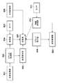
図7(a)は部門カウンタの保持形式を示すものであり、画像形成装置102には、部門数と、部門ごとのカウンタ種類数と、部門数分の部門IDを含む部門IDテーブル701と、部門毎の種類別カウンタのIDと各カウンタの値を含む部門カウンタテーブル702が保持されている。部門カウンタテーブル702を単に部門カウンタと呼ぶこともある。また、図7(b)は画像形成装置単位のカウンタ値である課金カウンタの保持形式を示す。本実施形態では、課金カウンタとして、カウンタ種類数703と、カウンタ種類毎のカウンタ値のテーブル704とを保持する。ここで画像形成装置単位のカウンタ値とは、ある1台の画像形成装置における、部門やユーザに係りないカウンタ値を示す。同じ種類のカウンタが部門カウンタと課金カウンタの両方にふくまれていれば、その種類について、この画像形成装置単位のカウンタ値と部門毎に集計されたカウンタ値の総和とは一致するはずである。
FIG. 7A shows a storage format of department counters. The
尚、本実施形態では、部門毎のカウンタID1と課金カウンタのカウンタID1とがトータルカウンタであるものとして説明する。もちろん、対応する種類別カウンタがあればトータルカウンタと同様に扱える。 In the present embodiment, description will be made assuming that the counter ID1 for each department and the counter ID1 of the charging counter are total counters. Of course, if there is a corresponding type counter, it can be handled in the same way as the total counter.
なお上記カウンタとは別に、或る時点におけるカウンタの複製、すなわちスナップショットが記憶部606に保持される。スナップショットの作成は、監視装置101からの指示に応じて行われる。後述するようにスナップショットは、画像形成動作の合間に作成される。
In addition to the counter, a copy of the counter at a certain time, that is, a snapshot is stored in the
図8は、図14,図15、図17のフローチャートで説明するカウンタ取得動作で監視装置101が取得した、画像形成装置についての部門カウンタ値、課金カウンタ値、及び、スナップショットとして取得したカウンタ値を保持するために、監視装置101が有するテーブルの一例を示す図である。図8の保持形式は基本的に図7で説明したカウンタ保持形式に従う。
FIG. 8 shows a department counter value, a charging counter value, and a counter value acquired as a snapshot for the image forming apparatus acquired by the
デバイス特定情報801には、該当する画像形成装置の識別情報たとえばIPアドレスが格納される。監視装置101が通信を行うべき画像形成装置を特定できる情報であれば、IPアドレスに限るものではない。データ取得時刻802は、カウンタ値を取得した時刻が記録され、部門カウンタ値と課金カウンタ値を整合性を保って取得できたかどうかの判断に用いることもできる。
The
トータル枚数808、812とは、用紙サイズや用紙種類、ジョブの種類に係らない、ある部門における全体のカウンタ値を示す。また、カラーコピー枚数809、813は、カラーの複写ジョブの出力枚数を示す。また、カラープリント枚数810、814は、カラーのPDL印刷出力枚数を示す。ここで、PDL印刷とは、外部のコンピュータからの画像形成装置へのPDLジョブ投入による印刷のことを指す。
The total number of
一方、課金カウンタ1(トータル枚数)815、821は、複数部門を跨いだ1台の画像形成装置全体としてのカウンタ値を示す。カウンタ815、808、812は整合性を保って取得したものであるため、カウンタ815の値はカウンタ808とカウンタ812の値の和と一致している。例では、カウンタ821は、カウンタ815,カウンタ808,カウンタ812を取得した後で取得した課金カウンタの値であり、その間に進行した印刷処理によってカウンタ値が増加している。また、カウンタ818(課金カウンタ4のカラーラージ)は用紙サイズが例えばA3以上のカラー印刷をした枚数を示し、カウンタ819(課金カウンタ5のモノクロラージ)は用紙サイズが例えばA3以上の白黒印刷をした枚数を示す。
On the other hand, charging counters 1 (total number of sheets) 815 and 821 indicate counter values of the entire image forming apparatus across a plurality of departments. Since the
課金カウンタについては、課金カウンタ2ないし5(カウンタ817ないし819)の和が課金カウンタ1(カウンタ816)に一致している。しかしながら、必ずしも一致する必要はない。例えば、課金カウンタ5を除いて図8に示されるカウンタ値保持テーブルを構築しても良い。
Regarding the charging counter, the sum of the charging counters 2 to 5 (
カウンタ821,822は、課金カウンタ815乃至819の一部のスナップショットである。
<カウンタ取得タイミング>
図9は、監視装置101が、部門カウンタと課金カウンタとを取得するタイミングとスナップショットの作成を画像形成装置に依頼をするタイミング、及び、部門カウンタと課金カウンタの整合性がとれない場合を説明する図である。図9中の左側から右側への矢印は時間の経過を現すものである。
<Counter acquisition timing>
FIG. 9 illustrates the timing when the
タイミング901〜904は、監視装置101が画像形成装置102から定期的に部門カウンタ値と課金カウンタ値を取得するタイミングである。タイミング908〜910は、不定期にスナップショットを作成するタイミングである。期間905〜907は、監視対象となる画像形成装置にてジョブが実行されている期間を示す。
図14のフローチャートを用いて詳細に説明するが、監視装置101は、定期的なカウンタ値取得では、課金カウンタ値、部門カウンタ値、もう一度課金カウンタ値の順に画像形成装置からカウンタ値を取得する。
As will be described in detail with reference to the flowchart of FIG. 14, the
監視装置101がタイミング901で部門カウンタ値と課金カウンタ値を取得した場合、ジョブ実行中でないため、初めに取得した課金カウンタ値と、最後に取得した課金カウンタ値とは一致する。このため、部門カウンタと課金カウンタの整合性が保たれ、カウンタ値の取得は成功したと判断する。しかし、タイミング902ではジョブ実行中であるため、初めに取得した課金カウンタ値と最後に取得した課金カウンタ値とは一致しないことがあり得る。一致しなければ部門カウンタと課金カウンタの整合性が保たれず、カウンタ値の取得は失敗と判断される。
When the
一方、監視装置101は、ジョブが実行されていないタイミング908,909,910などで画像形成装置にスナップショット作成を依頼する。ここで、部門カウンタ値と課金カウンタ値のデータ量は、スナップショットに比べて非常に大きいため、ジョブが実行されていないタイミングで取得することは困難である。これに対してスナップショットはカウンタの一部を対象としており、ジョブが実行されていない期間に複製を完了することができる。
On the other hand, the
<カウンタ取得に係る設定>
図10は、監視装置101が表示制御部206を介して表示装置209に表示する締め日受け付け画面の一例である。図10の例では、締め日指定方法として、日付指定、毎月最終日、管理サーバからの取得の3つの選択肢から、たとえば管理者が指定できる。日付指定の場合には、指定した日付も入力される。なお管理サーバとは管理装置107のことである。この画面での指定はコマンド処理部502によって受け付けられ、次に設定変更部503にて処理され、その結果を記憶部507に記録する。記憶部507に記録した締め日情報は、取得部504により、詳細には図12のステップS1202にて読み込まれる。
<Settings related to counter acquisition>
FIG. 10 is an example of a closing date reception screen displayed on the
図11は、監視装置101が保持する、カウンタ取得および送信に係る設定データの一例である。本設定データは記録部507によって、RAM203、あるいは、HDD208に格納されている。またこれらの設定データは不図示のユーザインターフェースにより管理者に入力されても、あるいは管理装置107から取得されてもよい。またその他の方法で設定されてもよい。
FIG. 11 is an example of setting data related to counter acquisition and transmission held by the
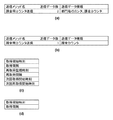
設定データには、送信メソッド名、対応する送信データの数、送信データの種類が含まれる。図11(a)及び図11(b)は、監視装置101から管理装置107へのデータ送信種類を表す例である。図11(a)は、課金用カウンタとして、部門カウンタ値と課金カウンタ値を送信する際の設定データの例である。図11(b)は、課金用カウンタとして課金カウンタ値のみを送信する際の設定データの例である。図11(a)の設定データは、たとえば販売会社から課金カウンタ値だけでなく、部門毎の課金情報を顧客に提示する場合などに、図11(b)の設定データは、部門毎の課金情報を顧客に提示しない場合に監視装置101の送信情報として設定される。
The setting data includes a transmission method name, the number of corresponding transmission data, and the type of transmission data. FIGS. 11A and 11B show examples of data transmission types from the
設定データにはまた、定期的に部門カウンタ値と課金カウンタ値とを取得するための時間の設定が含まれる。図11(c)は、定期的に部門カウンタ値と課金カウンタ値とを取得するための設定である。「取得」は、監視装置101の監視対象である全画像形成装置からのカウンタ値取得処理を示し、「再取得」は、「取得」処理で取得に失敗した画像形成装置を対象とした、取得対象となるカウンタ値の取得処理を示す。「取得間隔」と「再取得間隔」とでは、通常、「取得間隔」は例えば12時間、24時間程度であり、「再取得間隔」は、たとえば1から2時間程度である。
The setting data also includes time settings for periodically acquiring the department counter value and the billing counter value. FIG. 11C shows settings for periodically acquiring the department counter value and the billing counter value. “Acquisition” indicates counter value acquisition processing from all image forming apparatuses monitored by the
設定データにはさらに、スナップショットのための設定が含まれる。図11(d)は、スナップショット取得に係る設定であり、取得開始時刻と取得間隔を持つ。スナップショットの取得指示を画像形成装置に送信する時刻を示す。スナップショット取得間隔は、画像形成装置の通信負荷を軽減するために、図11(c)の取得間隔とは別に保持することが望ましい。なおスナップショットの取得指示の時刻は、当該指示が画像形成装置に対して送信される時刻であってスナップショットの取得の時刻ではないことに注意すべきである。 The setting data further includes settings for the snapshot. FIG. 11D shows settings related to snapshot acquisition, which has an acquisition start time and an acquisition interval. Indicates the time at which a snapshot acquisition instruction is transmitted to the image forming apparatus. The snapshot acquisition interval is desirably maintained separately from the acquisition interval of FIG. 11C in order to reduce the communication load of the image forming apparatus. Note that the snapshot acquisition instruction time is the time when the instruction is transmitted to the image forming apparatus, not the snapshot acquisition time.
<監視装置101によるカウンタ値の取得処理>
図12は、監視装置101が、ROM202に格納された監視プログラム405を実行して画像形成装置102からカウンタ値を取得する処理を示すフローチャートである。処理が開始される前に、RAM203、あるいは、HDD208に図11の形式にてデータが設定されている。
<Counter Value Acquisition Processing by
FIG. 12 is a flowchart illustrating processing in which the
ステップS1201において、部門カウンタ値と課金カウンタ値の定期取得処理を開始する。ここで開始する定期取得処理については、図13〜15のフローチャートを用いて詳細に後述する。定期取得処理は、たとえば図12の処理からは独立したプロセスとして実行される。したがって、いったんS1201で開始されれば、別途当該プロセスを停止するまで実行されて定期的にカウンタ値の取得が行われる。 次にステップS1202において、RAM203、あるいは、HDD208に締め日が設定されているかを判断する。ここで、締め日が設定されていると判断すると、ステップS1203において締め日と現在日を比較する。一致していると判断した場合は、ステップS1204に処理を行い、そうでない場合は、ステップS1205以降の処理を行う。
In step S1201, periodic acquisition processing of the department counter value and the billing counter value is started. The periodic acquisition process started here will be described in detail later using the flowcharts of FIGS. The periodic acquisition process is executed as a process independent of the process of FIG. 12, for example. Accordingly, once started in S1201, the counter value is periodically acquired until the process is separately stopped. Next, in step S1202, it is determined whether a closing date is set in the
一方、ステップS1202において、締め日が設定されていないと判断すると、ステップS1204以降の処理を行う。 On the other hand, if it is determined in step S1202 that the closing date has not been set, processing in step S1204 and subsequent steps is performed.
ステップS1204において、カウンタ値の取得に先立って、スナップショット作成処理と、取得処理とを開始する。ここで開始する処理については、それぞれ図16,17を用いて詳細に後述する。スナップショット作成処理、スナップショット取得処理とも、たとえば図12の処理からは独立したプロセスとして実行される。プロセスは画像形成装置ごとに用意してもよいし、また、ひとつのプロセスですべての画像形成装置に対応してもよい。説明の簡単化のために、ここでは図16、図17のプロセスは全画像形成装置に対してひとつであるとする。なお、S1204では、図16のプロセスに対して「開始」命令を発行する。 In step S1204, prior to acquisition of the counter value, snapshot creation processing and acquisition processing are started. The processing started here will be described later in detail with reference to FIGS. Both the snapshot creation process and the snapshot acquisition process are executed as processes independent of the process of FIG. 12, for example. The process may be prepared for each image forming apparatus, or all the image forming apparatuses may be handled in one process. For simplification of explanation, it is assumed here that the processes of FIGS. 16 and 17 are one for all image forming apparatuses. In S1204, a “start” command is issued to the process of FIG.
ステップS1205にて、監視装置101から管理サーバ107へカウンタ値を送信する時刻になるまで待機する。送信時刻については図示していないが、記録部507によってRAM203、あるいは、HDD208に格納されている。
In step S1205, the process waits until it is time to transmit the counter value from the
ステップS1206において、RAM203、あるいは、HDD208に図8の形式にて格納されているカウンタ値情報を参照する。定期取得データ、これは、部門カウンタ値と課金カウンタ値を指すものであるが、これらが有効なデータかを判断する。有効なデータとは、前回送信時刻よりも後に取得したデータである。取得時刻が前回送信時刻以前、あるいは、設定されていない場合、データは有効でないと判断する。なおカウンタ値の取得と送信とは本実施形態では別プロセスで非同期に行われるので、前回送信時刻として、例えばステップS1207でカウンタ値の送信を完了した日時を所定の不揮発の記憶領域に記憶しておく。記憶された時刻を「前回送信時刻」として参照すればよい。またカウンタ値の取得に失敗した場合には、カウンタ値の取得時刻として、通常は記録されない程度に古い日時を記録しておくことによってもデータが有効でないことは判断でき、逆にデータが有効であることも判断できる。
In step S1206, the counter value information stored in the
ステップS1206にて有効な定期取得データがあると判断すると、ステップS1207の処理を行う。ステップS1207では、RAM203、あるいは、HDD208に格納されている部門カウンタ値、課金カウンタ値を送信制御部509がNetworkI/F204経由で管理サーバ107に送信する。
If it is determined in step S1206 that there is valid periodic acquisition data, the process of step S1207 is performed. In step S1207, the
一方、ステップS1206にて有効な定期取得データがないと判断すると、スナップショット送信に係るステップS1209、S1210の処理を行う。 On the other hand, if it is determined in step S1206 that there is no valid periodic acquisition data, the processing in steps S1209 and S1210 related to snapshot transmission is performed.
ステップS1209において、図8の形式にて格納されているカウンタ情報のうち、取得時刻820から有効なデータであるかを判断する。判断方法はステップS1206と同様である。
In step S1209, it is determined whether the counter information stored in the format of FIG. 8 is valid data from the
ステップS1209において有効であると判断すると、ステップS1210にて、スナップショットとして取得した課金カウンタ値を送信制御部509がNetworkI/F204経由で管理サーバ107に送信する。
If it is determined in step S1209 that it is valid, in step S1210, the
ステップS1208で、その日の管理サーバ107へのカウンタ情報送信が終わったと判断すると、スナップショット作成、取得処理を終了し、日付が変わるまで待機したのち、ステップS1202に戻る。そうでない場合は、ステップS1205に戻り、次の送信時刻まで待機する。S1208では例えば、監視対象の画像形成装置すべてについて、カウンタ値の取得および送信の試みが完了したことをもって、終了と判断される。終了した場合にはスナップショットももはや不要なので、S1204で開始した図16のプロセスの対して「終了」命令を送信して、スナップショットの作成処理を中止させる。
If it is determined in step S1208 that the transmission of the counter information to the
<カウンタ値の定期取得処理>
図13、14、15のフローチャートを用いて、ステップS1201で開始する定期取得処理を詳細に説明する。これらフローチャートは、
まず、図13は、定期取得処理全体を表すフローチャートで、図12のステップS1201で実行が開始される。これらフローチャートで示す処理は、監視装置101のROM202に格納された監視プログラム405にて実行されるものである。
<Counter value periodic acquisition processing>
The periodic acquisition process started in step S1201 will be described in detail using the flowcharts of FIGS. These flowcharts
First, FIG. 13 is a flowchart showing the entire periodic acquisition process, and the execution is started in step S1201 of FIG. The processes shown in these flowcharts are executed by the
ステップS1301にて、RAM203、または、HDD208に格納された図11(c)の取得開始時刻を読み込こむ。現在時刻が「次回取得開始時刻」以降であると判断すると、ステップS1302以降の処理を行う。現在時刻が「次回取得開始時刻」より前であると判断すると、ステップS1304以降の処理を行う。
In step S1301, the acquisition start time in FIG. 11C stored in the
ステップS1302において、全監視対象画像形成装置から部門カウンタ値と課金カウンタ値とを取得する。本ステップの処理詳細は、図14のフローチャートを用いて詳細に後述する。 In step S1302, the department counter value and the charge counter value are acquired from all the monitoring target image forming apparatuses. Details of the processing in this step will be described later in detail using the flowchart of FIG.
取得処理終了後、ステップS1303にて、「次回取得開始時刻」に「取得間隔」を加算し、新しい「次回取得開始時刻」として設定する。 After completion of the acquisition process, in step S1303, “acquisition interval” is added to “next acquisition start time” and set as a new “next acquisition start time”.
ステップS1304において、現在時刻が「次回再取得開始時刻」以降であると判断すると、ステップS1305以降の処理を行う。現在時刻が「次回再取得開始時刻」以前であると判断すると、ステップS1301に戻る。 If it is determined in step S1304 that the current time is after the “next reacquisition start time”, the processing from step S1305 is performed. If it is determined that the current time is before the “next reacquisition start time”, the process returns to step S1301.
ステップS1305において、ステップS1302の取得処理で取得に失敗した画像形成装置から部門カウンタ値と課金カウンタ値とを取得する。本ステップの処理詳細は、図15のフローチャートを用いて詳細に後述する。 In step S1305, the department counter value and the charge counter value are acquired from the image forming apparatus that has failed to be acquired in the acquisition process in step S1302. Details of the processing in this step will be described later in detail using the flowchart of FIG.
取得処理終了後、ステップS1306にて、「次回再取得開始時刻」に「再取得間隔」を加算し、新しい「次回再取得開始時刻」として設定する。 After completion of the acquisition process, in step S1306, “re-acquisition interval” is added to “next re-acquisition start time” to set as a new “next re-acquisition start time”.
<監視対象の画像形成装置からのカウンタ値の取得処理>
図14のフローチャートを用いて、ステップS1302の処理を詳細に説明する。
<Counter Value Acquisition Process from Monitored Image Forming Apparatus>
The process of step S1302 will be described in detail using the flowchart of FIG.
ステップS1401にて、画像形成装置から課金カウンタ値を取得する。監視装置101からの課金カウンタ取得要求は、コマンド発行部508が発行し、送信制御部509がNetworkI/F204を介して、画像形成装置のコマンド処理部602に到達する。そして、画像形成装置の取得部603が課金カウンタ値を取得し、それを送信制御部605がNetworkI/F306経由で監視装置101に送信される。S1401で取得する課金カウンタ値は、図7のテーブル703,704に相当する。
In step S1401, a charging counter value is acquired from the image forming apparatus. The accounting counter acquisition request from the
ステップS1402にて、部門数を取得する。監視装置101と画像形成装置とのデータ授受の経路はステップS1401と同様である。S1402で取得する部門数は、図7のテーブル701に含まれている。S1403では、部門カウンタ数を取得する。
In step S1402, the number of departments is acquired. The data exchange path between the
ステップS1404にて部門カウンタ数分の部門カウンタ値を画像形成装置から取得する。S1404で取得する部門カウンタ値は、各部門について、図7のテーブル702に相当する。 In step S1404, department counter values for the number of department counters are acquired from the image forming apparatus. The department counter value acquired in S1404 corresponds to the table 702 in FIG. 7 for each department.
ステップS1405にて全部門カウンタを取得していないと判断すると、ステップS1404に戻り、全部門カウンタを取得したと判断すると、ステップS1406以降の処理を行う。 If it is determined in step S1405 that all department counters have not been acquired, the process returns to step S1404. If it is determined that all department counters have been acquired, the processing from step S1406 is performed.
ステップS1406にて全部門について処理してないと判断すると、ステップS1403に戻り、全部門について処理したと判断すると、ステップS1407以降の処理を行う。 If it is determined in step S1406 that all the departments have not been processed, the process returns to step S1403. If it is determined that all the departments have been processed, the processes in and after step S1407 are performed.
全部門について部門カウンタ値取得処理が終わると、ステップS1407にて、再度、課金カウンタを取得する。このように、課金カウンタは、部門カウンタの取得の前後において取得される。 When the department counter value acquisition processing is completed for all the departments, a charging counter is acquired again in step S1407. In this way, the billing counter is acquired before and after the department counter is acquired.
ステップS1408にて、ステップS1401で取得した課金カウンタ値とステップS1407で取得した課金カウンタ値とを比較する。一致していると判断すると、ステップS1409以降の処理を行い、一致していないと判断すると、ステップS1410以降の処理を行う。 In step S1408, the charging counter value acquired in step S1401 is compared with the charging counter value acquired in step S1407. If it is determined that they match, the processing after step S1409 is performed, and if it is determined that they do not match, the processing after step S1410 is performed.
ステップS1409では、部門カウンタ値と課金カウンタ値とが整合が取れていると判断し、データ取得時刻と取得したカウンタ値をRAM203、あるいは、HDD208に図8の形式にて格納する。ここで格納されるのは、データ取得時刻802から課金カウンタ819までである。
In step S1409, it is determined that the department counter value and the accounting counter value are consistent, and the data acquisition time and the acquired counter value are stored in the
一方、ステップS1410では、部門カウンタ値と課金カウンタ値との整合がとれていないので、取得失敗を示す情報をRAM203、あるいは、HDD208に格納する。取得失敗を示す情報の保持方法の一例として、データ取得時刻802として、記憶されている前回データ送信時刻以前の時刻、例えば、1970年1月1日0時0分0秒、などの所定の値を設定する。
On the other hand, in step S1410, since the department counter value and the charging counter value are not matched, information indicating acquisition failure is stored in the
ステップS1411にて、全画像形成装置についてカウンタ取得処理が終わったと判断すると、終了する。 If it is determined in step S1411 that the counter acquisition process has been completed for all the image forming apparatuses, the process ends.
図13、図15のフローチャートにて、カウンタ値の取得に成功したか否かを図8に含まれる取得時刻802から判断することができる。あるいは、フラグを設けて、成功ならば1、失敗ならば0をRAM203、または、HDD208に格納するという方法をとることもできる。
In the flowcharts of FIGS. 13 and 15, it can be determined from the
<カウンタ値の再取得処理>
図15を用いて、ステップS1305の処理を詳細に説明する。
<Counter value reacquisition processing>
The process of step S1305 will be described in detail with reference to FIG.
ステップS1501において、対象としている画像形成装置のカウンタ値取得に失敗したかどうかを判断する。成功したと判断した場合は、ステップS1507以降の処理を行う。失敗したと判断して場合は、ステップS1502の処理を行う。 In step S1501, it is determined whether the counter value acquisition of the target image forming apparatus has failed. If it is determined that the process has succeeded, the process from step S1507 is performed. If it is determined that the process has failed, the process of step S1502 is performed.
ステップS1502からステップS1504の処理は、ステップS1401〜S1407の処理と同じであるので、ここでは省略する。ここでS1503は図14のステップS1402〜S1406を含む。 Since the processing from step S1502 to step S1504 is the same as the processing from step S1401 to S1407, it is omitted here. Here, S1503 includes steps S1402 to S1406 of FIG.
ステップS1505において、ステップS1502で取得した課金カウンタ値とステップS1504で取得した課金カウンタ値とを比較する。一致しないと判断すると、ステップS1507以降の処理を行い、一致すると判断するとステップS1508以降の処理を行う。 In step S1505, the charging counter value acquired in step S1502 is compared with the charging counter value acquired in step S1504. If it is determined that they do not match, the processing after step S1507 is performed, and if it is determined that they match, the processing after step S1508 is performed.
ステップS1506では、ステップS1409と同様に取得した部門カウンタ値と課金カウンタ値とデータ取得時刻とを図8の形式にてRAM203、あるいは、HDD208に格納する。
In step S1506, the department counter value, billing counter value, and data acquisition time acquired in the same manner as in step S1409 are stored in the
ステップS1507において、次の2点を判断する。1つめは、全失敗デバイスの再取得処理をしたか、2つめは、現在時刻が「次回取得開始時刻」以降でないか、である。2つめの判断は、本実施形態において、再取得処理の途中であっても、定期取得処理開始時刻になったら再取得処理を中止するようにしているために必要なものであって、本発明において必須のものではない。1つめ、2つめの判断のうち1つ以上が合致した場合、YESであると判断し、1つも合致しない場合、NOであると判断する。 In step S1507, the following two points are determined. The first is whether or not all failed devices have been reacquired, and the second is whether the current time is after the “next acquisition start time”. In the present embodiment, the second determination is necessary because the reacquisition process is stopped when the periodic acquisition process start time is reached even during the reacquisition process. Is not essential. If one or more of the first and second judgments match, it is determined to be YES, and if none match, it is determined to be NO.
ステップS1507において、YESであると判断すると再取得処理を終了し、NOであると判断すると、ステップS1508において、全画像形成装置の処理が終了したか判断する。終了したと判断すると、再取得処理を終了し、そうでない場合は、ステップS1501に戻る。 If it is determined as YES in step S1507, the reacquisition process is terminated. If it is determined as NO, it is determined in step S1508 whether the processes of all the image forming apparatuses are completed. If it is determined that the process has been completed, the reacquisition process is terminated. If not, the process returns to step S1501.
<スナップショット作成処理>
図16と図17を用いて、スナップショットに係る処理を詳細に説明する。これらフローチャートは、監視装置101のROM202に格納された監視プログラム405の動作を示すものである。
<Snapshot creation process>
The process related to the snapshot will be described in detail with reference to FIGS. These flowcharts show the operation of the
図16は、監視装置101の画像形成装置へのスナップショット作成依頼に係る処理を示すフローチャートである。この処理は、図12のS1204にて開始される独立したプロセスである。
FIG. 16 is a flowchart illustrating processing relating to a snapshot creation request to the image forming apparatus of the
ステップS1601において、データ受信を待ち受ける。データ送信元は、監視装置101自身と画像形成装置である。
In step S1601, it waits for data reception. The data transmission source is the
データを受信すると、ステップS1602において、受信データ内容を判断する。受信データが監視装置自身からの「開始」である場合、ステップS1603にて、監視装置101の監視対象である全画像形成装置に対して印刷状態変化通知依頼を送信し、印刷状態が変化した場合、そのことを通知するよう依頼する。監視装置101からの印刷状態変化通知依頼は、画像形成装置のコマンド処理部602によって受信され、印刷状態変化通知先情報が記憶部606に格納される。
When data is received, the content of the received data is determined in step S1602. When the received data is “start” from the monitoring apparatus itself, in step S1603, a print state change notification request is transmitted to all image forming apparatuses monitored by the
受信データが監視装置自身からの「終了」である場合、ステップS1604にて、監視装置101の監視対象である全画像形成装置に対して、印刷状態変化通知依頼取り消しを通知し、処理を終了する。
If the received data is “end” from the monitoring apparatus itself, in step S1604, the cancellation of the print state change notification request is notified to all image forming apparatuses monitored by the
受信データがいずれかの画像形成装置からの「印刷状態変化」である場合、ステップ1605にて通知された状態が印刷中であるか否かを判断する。「印刷状態変化」は画像形成装置の印刷状態が変化した時に通知されるものであって、印刷中から印刷していない状態になった時、及び、印刷していない状態から印刷中になった時に通知されるものである。 If the received data is “printing state change” from any of the image forming apparatuses, it is determined whether or not the state notified in step 1605 is printing. “Printing status change” is notified when the printing status of the image forming apparatus has changed. When printing has changed from printing to printing, and printing has not started. It is sometimes notified.
ステップS1605において、印刷中であると判断した場合は、ステップS1603に分岐して印刷状態変化通知依頼を送信する。ただしS1605から分岐した場合には、S1603で判定の対象とした印刷状態変化通知を応答した画像形成装置を対象とする。その後ステップS1601に戻り、データ受信を待ち受ける。印刷していないと判断した場合、ステップS1606にて画像形成装置にスナップショット作成の依頼を送信する。この場合も対象はS1603で判定の対象とした印刷状態変化通知を応答した画像形成装置である。その後ステップS1601に戻り、データ受信を待ち受ける。 If it is determined in step S1605 that printing is in progress, the process branches to step S1603 to transmit a print state change notification request. However, if the process branches off from S1605, the target is the image forming apparatus that has responded to the print state change notification to be determined in S1603. Thereafter, the process returns to step S1601 to wait for data reception. If it is determined that printing has not been performed, a snapshot creation request is transmitted to the image forming apparatus in step S1606. In this case as well, the target is the image forming apparatus that has responded to the print state change notification determined in S1603. Thereafter, the process returns to step S1601 to wait for data reception.
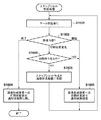
図17は、監視装置101が、画像形成装置に作成を依頼したスナップショットデータを定期的に取得する処理を示すフローチャートである。図17の処理も独立したプロセスである。ステップS1701にて、現在時刻が取得時刻以降であるかを判断する。取得時刻以降であると判断するとステップS1702以降の処理を行う。取得時刻は、図11(d)の取得開始時刻を参照して得られる。
FIG. 17 is a flowchart illustrating processing in which the
ステップS1702において、画像形成装置にスナップショット取得要求を出す。この取得要求送信のプロトコルの一例としてSNMP(Simple Network Management Protocol)がある。 In step S1702, a snapshot acquisition request is issued to the image forming apparatus. An example of the acquisition request transmission protocol is SNMP (Simple Network Management Protocol).
ステップS1703において、スナップショット取得が成功したか否かを判断する。成功か否かは、たとえば画像形成装置からの応答により判断できる。成功した場合は、ステップS1704にて、図8の形式にてRAM203,あるいは、HDD208に取得したカウンタ値およびデータ取得時刻を格納する。そして、ステップS1705において、次回取得時刻を更新する。
In step S1703, it is determined whether snapshot acquisition is successful. Whether it is successful or not can be determined by, for example, a response from the image forming apparatus. If successful, in step S1704, the acquired counter value and data acquisition time are stored in the
ステップS1706において、割り込み命令の有無を判断する。処理終了の割り込み命令があると判断すると、スナップショットデータ取得処理を終了する。そうでない場合、ステップS1701に戻る。割り込み命令は、たとえば図12のS1208で終了と判定された場合に送信される。この割り込み命令は、図16の処理に対する「終了」命令と同じものであってもよい。 In step S1706, the presence / absence of an interrupt instruction is determined. When it is determined that there is an interrupt instruction for ending the process, the snapshot data acquisition process is ended. Otherwise, the process returns to step S1701. The interrupt instruction is transmitted, for example, when it is determined in S1208 in FIG. This interrupt command may be the same as the “end” command for the processing of FIG.
以上説明したとおり、課金カウンタ情報取得中に印刷が実行され、部門カウンタ値と課金カウンタ値との整合性が取れない状態が続いても、画像形成装置の印刷状態を監視し、印刷していない時にスナップショット生成する。これにより、課金に必要最低限のデータを管理サーバに通知することが可能となる。
[実施形態2]
実施形態2では、監視装置101から管理装置(管理サーバ)107に対して送信するものと定義された課金用カウンタのデータの種類によってスナップショットを送信するかどうかを判断する。ステップS1209において、スナップショットの有効性を判断している。その際に、本実施形態では、監視装置101が保持している管理サーバ107への送信データ定義が例えば図11(a)に示すように部門カウンタと課金カウンタとを含む場合、スナップショットデータでは不十分であり無効であると判断して管理サーバに送信しない。
As described above, even if printing is executed while the accounting counter information is being acquired and the consistency between the department counter value and the accounting counter value continues, the printing status of the image forming apparatus is monitored and printing is not performed. Sometimes generate snapshots. This makes it possible to notify the management server of the minimum data necessary for charging.
[Embodiment 2]
In the second embodiment, it is determined whether or not to transmit a snapshot based on the data type of the accounting counter defined to be transmitted from the
これにより、不十分でサービス提供のために使用できない無駄なデータを送信することがなくなる。 As a result, useless data that is insufficient and cannot be used for service provision is not transmitted.
また、上述した以外にも、事前にスナップショットの有効性を判断し、管理サーバ107への送信データ定義から、カウンタの種類がスナップショットデータでは不十分であり有効ではないと判断される場合には、画像形成装置からスナップショットデータの取得自体を行わないことも実施可能である。つまり、画像形成装置が部門課金による管理を行うか否かの判断により、画像形成装置が部門課金による管理が行われる場合にのみ、前述したようなスナップショットデータの複製指示や取得処理を実行することも可能である。
In addition to the above, when the validity of the snapshot is determined in advance, and it is determined from the definition of the transmission data to the
[実施形態3]
本実施形態では、定期取得処理及び再取得処理では長期間課金用データを取得出来ない画像形成装置からスナップショットデータを取得する。このために、S1206において、あるいはS1206の直前に、データ取得時刻802と現在時刻とを比較して、所定時間以上、部門カウンタ値と課金カウンタ値とを取得していないと判断した場合、ただちにスナップショットを取得する。すなわちこの場合には定期取得データの有無にかかわらずS1209に分岐する。これにより、課金に必要なデータを取得できない画像形成装置が減る。
[Embodiment 3]
In this embodiment, snapshot data is acquired from an image forming apparatus that cannot acquire long-term charging data in the periodic acquisition process and the re-acquisition process. Therefore, in S1206 or immediately before S1206, when the
[実施形態4]
画像形成装置のなかには、省電力を目的として、一定時間ジョブ実行を指示されないと、使用電力量を減らすためのモードに移行するものがある。また、電源をOFFする時刻をスケジュール情報として画像形成装置自身、あるいは、ネットワーク接続された電源OFFスケジュール制御装置に保持している場合、そこから情報を取得し、RAM203、あるいは、HDD208に格納する。
[Embodiment 4]
Some image forming apparatuses shift to a mode for reducing the amount of power used when a job execution is not instructed for a certain period of time for the purpose of power saving. If the power-off time is stored as schedule information in the image forming apparatus itself or the power-off schedule control apparatus connected to the network, the information is acquired from the information and stored in the
ステップS1203にて、締め日であると判断した場合、ステップS1204で電源OFFスケジュールに合わせて、一例として、電源OFF直前にスナップショットを取得するような値を図11(c)の取得開始時刻、取得間隔を設定する。また、監視装置101は、ステップS1205にて使用電力を減らすモードへの移行予告通知を受信すると、即座にスナップショットを取得する。これにより、画像形成装置が省電力のための設定をなされていても、課金に必要なデータを取得することが可能となる。
When it is determined in step S1203 that it is a closing date, in step S1204, as an example, a value for acquiring a snapshot immediately before the power is turned off is acquired as the acquisition start time in FIG. Set the interval. In addition, when the
[他の実施形態]
本発明は、以下の処理を実行することによっても実現される。即ち、上述した実施例の機能を実現するソフトウェア(プログラム)を、ネットワーク又は各種記憶媒体を介してシステム或いは装置に供給し、そのシステム或いは装置のコンピュータ(またはCPUやMPU等)がプログラムを読み出して実行する処理である。
[Other Embodiments]
The present invention is also realized by executing the following processing. That is, software (program) for realizing the functions of the above-described embodiments is supplied to a system or apparatus via a network or various storage media, and a computer (or CPU, MPU, etc.) of the system or apparatus reads the program. It is a process to be executed.
Claims (14)
前記画像形成装置は、
カウンタ情報として、複数の種類のカウンタ値を、前記画像形成装置の記憶装置に記録する記録手段と、
前記カウンタ情報の一部を、画像形成動作の合間に記憶装置に複製する複製手段とを有し、
前記監視装置は、
前記記憶装置に記録された複数の種類のカウンタ値を取得する取得手段と、
前記取得した前記複数の種類のカウンタ値の間に整合性がある場合には、取得したカウンタ値を有効なカウンタ値として格納する格納手段と、
前記画像形成装置から、前記複製手段により複製されたカウンタ情報の一部の取得を試みる試行手段と、を有し、
前記格納手段は、前記取得手段により取得された前記複数の種類のカウンタ値の間に整合性がない場合には、前記試行手段により取得された、前記複製手段により複製されたカウンタ情報の一部を有効なカウンタ値として格納することを特徴とする管理システム。 A management system including an image forming apparatus that manages the number of sheets output after image formation as counter information , and a monitoring apparatus connected to the image forming apparatus ,
The image forming apparatus includes:
Recording means for recording a plurality of types of counter values in the storage device of the image forming apparatus as counter information;
A copy unit for copying a part of the counter information to a storage device between image forming operations;
The monitoring device,
Obtaining means for obtaining a plurality of types of counter values recorded in the storage device;
When there is consistency between the acquired types of counter values, storage means for storing the acquired counter values as valid counter values;
A trial unit that attempts to acquire a part of the counter information duplicated by the duplication unit from the image forming apparatus,
It said storage means, if there is no consistency between the acquired plurality of types of counter values by the acquisition unit is acquired by the trial unit, a part of the counter information which has been copied by the copy means Is stored as an effective counter value.
前記複製手段は、前記複製の指示の受信に応じて、画像形成動作の合間に前記カウンタ情報の一部を前記記憶装置に複製することを特徴とする請求項1に記載の管理システム。 The monitoring device, prior to acquisition of the count value by the acquisition means, to the image forming apparatus further comprises instruction means for instructing replication by the duplication unit,
The replication unit, the management system of claim 1, wherein in response to receiving the indication of replication, and wherein to copy a part of the counter information in between the image forming operation in the storage device.
前記格納手段は、前記取得したトータルカウンタと部門カウンタとのカウンタ値の間に整合性がない場合には、前記試行手段により取得された前記複製の指示の受信に応じて複製されたカウンタ情報の一部を有効なカウンタ値として格納することを特徴とする請求項2に記載の管理システム。 The acquisition means acquires counter values of the total counter and department counter,
It said storage means, if there is no consistency between the counter value of the total counter and the sector counter and the acquisition of replicated counter information in response to the reception of an instruction of said acquired by the trial unit replication 3. The management system according to claim 2, wherein a part is stored as a valid counter value.
前記格納手段は、取得した2つのトータルカウンタのカウンタ値が一致していれば整合性があると判定し、前記取得手段が取得したトータルカウンタとそのほかの種類のカウンタとのカウンタ値を有効な値として格納することを特徴とする請求項1または2に記載の管理システム。 The acquisition means acquires the counter value of the total counter that records the total number of outputs before and after acquiring the counter value of other types of counters,
The storage means determines that there is consistency if the counter values of the two acquired total counters match, and determines that the counter values of the total counter acquired by the acquiring means and other types of counters are valid values. The management system according to claim 1, wherein the management system is stored as:
前記監視装置は、格納した前記有効なカウンタ値を前記管理装置に送信することを特徴とする請求項1乃至5のいずれか一項に記載の管理システム。 A management device connected to the monitoring device;
The management system according to claim 1, wherein the monitoring device transmits the stored valid counter value to the management device.
前記取得した前記複数の種類のカウンタ値の間に整合性がある場合には、取得したカウンタ値を有効なカウンタ値として格納する格納手段と、
前記画像形成装置から、前記画像形成装置において画像形成動作の合間に記憶装置に複製されたカウンタ情報の一部の取得を試みる試行手段と、を有し、
前記格納手段は、前記取得した前記複数の種類のカウンタ値の間に整合性がない場合には、前記試行手段により取得された、前記複製されたカウンタ情報の一部を有効なカウンタ値として格納することを特徴とする監視装置。 An acquisition means for acquiring a plurality of types of counter values recorded as counter information in a storage device of the image forming apparatus ;
When there is consistency between the acquired types of counter values, storage means for storing the acquired counter values as valid counter values;
Trial means for attempting to acquire a part of the counter information copied to the storage device between image forming operations in the image forming apparatus from the image forming apparatus ,
It said storage means, if there is no consistency between the acquired plurality of types of counter values obtained by the trial unit, a portion of the replicated been counter information as valid counter values A monitoring device characterized by storing.
前記画像形成装置は、前記複製の指示の受信に応じて、画像形成動作の合間に前記カウンタ情報の一部を前記記憶装置に複製することを特徴とする請求項7に記載の監視装置。 Prior to acquisition of the counter value by the acquisition unit, the image forming apparatus further includes an instruction unit for instructing copying of counter information,
Wherein the image forming apparatus, in response to reception of an instruction of the copy, the monitoring device according to some of the counter information in between the image forming operation to claim 7, characterized in that replicate in the storage device.
前記格納手段は、前記取得したトータルカウンタと部門カウンタとのカウンタ値の間に整合性がない場合には、前記試行手段により取得された前記複製の指示の受信に応じて複製されたカウンタ情報の一部を有効なカウンタ値として格納することを特徴とする請求項8に記載の監視装置。 The acquisition means acquires counter values of the total counter and department counter,
It said storage means, if there is no consistency between the counter value of the total counter and the sector counter and the acquisition of replicated counter information in response to the reception of an instruction of said acquired by the trial unit replication The monitoring apparatus according to claim 8, wherein a part is stored as an effective counter value.
前記格納手段は、取得した2つのトータルカウンタのカウンタ値が一致していれば整合性があると判定し、前記取得手段が取得したトータルカウンタとそのほかの種類のカウンタとのカウンタ値を有効な値として格納することを特徴とする請求項7または8に記載の監視装置。 The acquisition means acquires the counter value of the total counter that records the total number of outputs before and after acquiring the counter value of other types of counters,
The storage means determines that there is consistency if the counter values of the two acquired total counters match, and determines that the counter values of the total counter acquired by the acquiring means and other types of counters are valid values. The monitoring device according to claim 7, wherein the monitoring device is stored as
前記画像形成装置が、カウンタ情報として、複数の種類のカウンタ値を、前記画像形成装置の記憶装置に記録し、前記カウンタ情報の一部を、画像形成動作の合間に記憶装置に複製する工程と、
前記監視装置が、前記記憶装置に記録された複数の種類のカウンタ値を取得し、前記取得した前記複数の種類のカウンタ値の間に整合性がある場合には、取得したカウンタ値を有効なカウンタ値として格納し、前記画像形成装置から、前記複製する工程により複製されたカウンタ情報の一部の取得を試みる工程と、を有し、
前記格納する工程では、前記取得した前記複数の種類のカウンタ値の間に整合性がない場合には、前記取得を試みる工程により取得された、前記複製する工程により複製されたカウンタ情報の一部を有効なカウンタ値として格納する
ことを特徴とする管理方法。 A management method in a management system that includes an image forming apparatus that manages the number of sheets output after image formation as counter information , and a monitoring apparatus connected to the image forming apparatus ,
The image forming apparatus, as counter information, a plurality of types of the counter value, and recorded in the storage device of the image forming apparatus, a part of said counter information, as engineering to duplicate the storage devices in between the image forming operation When,
The monitoring device, wherein to acquire a plurality of types of counter value recorded in the storage device, wherein when there is consistency between the acquired plurality of types of counter values, enable acquired counter value such stored as a counter value, from the image forming apparatus has, the more Engineering attempting a part of acquisition of the counter information is replicated by a process of replicating,
Wherein in the storage to process, wherein when there is no consistency between the acquired plurality of kinds of counter values, said acquired by the step of attempting to acquire a part of the counter information is replicated by a process that replicates Is stored as an effective counter value.
前記取得した前記複数の種類のカウンタ値の間に整合性がある場合には、取得したカウンタ値を有効なカウンタ値として格納する格納手段と、
前記画像形成装置から、前記画像形成装置において画像形成動作の合間に記憶装置に複製されたカウンタ情報の一部の取得を試みる試行手段と、
してコンピュータを機能させるためのプログラムであって、
前記格納手段は、前記取得した前記複数の種類のカウンタ値の間に整合性がない場合には、前記試行手段により取得された、前記複製されたカウンタ情報の一部を有効なカウンタ値として格納することを特徴とするプログラム。 An acquisition means for acquiring a plurality of types of counter values recorded as counter information in a storage device of the image forming apparatus ;
When there is consistency between the acquired types of counter values, storage means for storing the acquired counter values as valid counter values;
Trial means for attempting to acquire a part of the counter information copied to the storage device between image forming operations in the image forming apparatus from the image forming apparatus ;
And a program to make the computer function,
It said storage means, if there is no consistency between the acquired plurality of types of counter values obtained by the trial unit, a portion of the replicated been counter information as valid counter values A program characterized by storing.
Priority Applications (2)
| Application Number | Priority Date | Filing Date | Title |
|---|---|---|---|
| JP2011226225A JP5865003B2 (en) | 2011-10-13 | 2011-10-13 | Management system, monitoring apparatus and management method |
| US13/608,342 US8953193B2 (en) | 2011-10-13 | 2012-09-10 | Management system, monitoring apparatus and management |
Applications Claiming Priority (1)
| Application Number | Priority Date | Filing Date | Title |
|---|---|---|---|
| JP2011226225A JP5865003B2 (en) | 2011-10-13 | 2011-10-13 | Management system, monitoring apparatus and management method |
Publications (3)
| Publication Number | Publication Date |
|---|---|
| JP2013088874A JP2013088874A (en) | 2013-05-13 |
| JP2013088874A5 JP2013088874A5 (en) | 2014-11-20 |
| JP5865003B2 true JP5865003B2 (en) | 2016-02-17 |
Family
ID=48085799
Family Applications (1)
| Application Number | Title | Priority Date | Filing Date |
|---|---|---|---|
| JP2011226225A Expired - Fee Related JP5865003B2 (en) | 2011-10-13 | 2011-10-13 | Management system, monitoring apparatus and management method |
Country Status (2)
| Country | Link |
|---|---|
| US (1) | US8953193B2 (en) |
| JP (1) | JP5865003B2 (en) |
Families Citing this family (7)
| Publication number | Priority date | Publication date | Assignee | Title |
|---|---|---|---|---|
| JP6575078B2 (en) * | 2015-02-26 | 2019-09-18 | 株式会社リコー | Information processing system, information processing apparatus, device, information processing method, and program |
| JP6287942B2 (en) * | 2015-04-20 | 2018-03-07 | キヤノンマーケティングジャパン株式会社 | Information processing apparatus, processing method thereof, and program |
| JP6281541B2 (en) * | 2015-08-26 | 2018-02-21 | コニカミノルタ株式会社 | Image forming system, image forming apparatus, and image forming method |
| JP2017084008A (en) * | 2015-10-26 | 2017-05-18 | 富士ゼロックス株式会社 | Information processing apparatus, image forming system, and program |
| JP7152329B2 (en) * | 2019-01-30 | 2022-10-12 | シャープ株式会社 | Device information monitoring device |
| JP7350551B2 (en) | 2019-07-22 | 2023-09-26 | キヤノン株式会社 | Device management system and its control method |
| DE102019127400B3 (en) * | 2019-10-11 | 2020-10-22 | Canon Production Printing Holding B.V. | Method for simulating a printing process for print jobs on a digital high-performance printing system |
Family Cites Families (5)
| Publication number | Priority date | Publication date | Assignee | Title |
|---|---|---|---|---|
| JP4012050B2 (en) * | 2002-11-27 | 2007-11-21 | キヤノン株式会社 | Information processing apparatus, information processing method, and control program |
| JP4659667B2 (en) * | 2005-06-08 | 2011-03-30 | キヤノン株式会社 | Information processing apparatus and information processing method |
| JP4953746B2 (en) * | 2006-09-26 | 2012-06-13 | キヤノン株式会社 | Management apparatus and control method thereof |
| US7817658B2 (en) * | 2006-12-08 | 2010-10-19 | Sharp Laboratories Of America, Inc. | Systems and methods for preparing a usage report with counter information |
| JP5473651B2 (en) * | 2010-02-08 | 2014-04-16 | キヤノン株式会社 | Management system, monitoring apparatus, and information processing method |
-
2011
- 2011-10-13 JP JP2011226225A patent/JP5865003B2/en not_active Expired - Fee Related
-
2012
- 2012-09-10 US US13/608,342 patent/US8953193B2/en not_active Expired - Fee Related
Also Published As
| Publication number | Publication date |
|---|---|
| JP2013088874A (en) | 2013-05-13 |
| US20130094046A1 (en) | 2013-04-18 |
| US8953193B2 (en) | 2015-02-10 |
Similar Documents
| Publication | Publication Date | Title |
|---|---|---|
| JP5865003B2 (en) | Management system, monitoring apparatus and management method | |
| JP5424765B2 (en) | Monitoring device and information processing method | |
| JP5677173B2 (en) | Image forming apparatus, network system, image forming apparatus control method, and program | |
| CN102855101B (en) | Print system and the Workflow management method for print system | |
| US8760690B2 (en) | Print server adapted to implement a pull-printing technique with a printing apparatus | |
| JP4266957B2 (en) | Centralized monitoring system and control method therefor, and host device and control method therefor | |
| JP5173495B2 (en) | Information processing apparatus, job processing method, and program | |
| JP5473651B2 (en) | Management system, monitoring apparatus, and information processing method | |
| EP2605122A2 (en) | Information processing system, image forming apparatus, management method, and storage medium | |
| JP6298302B2 (en) | Network device and data identification method | |
| JP2011128995A (en) | Log information management system, control method therefor, and storage medium | |
| US8400666B2 (en) | Information processing apparatus and information processing method | |
| US8755074B2 (en) | Updating a job list in a server after shutdown when the server is rebooted | |
| CN101047759A (en) | Image processing apparatus, image forming apparatus, image forming system, and control method for these | |
| JP2010204746A (en) | Print control device, control method, and program | |
| US10642557B2 (en) | Data communication and transmission for information processing devices in a network | |
| JP2008083862A (en) | Management device and control method therefor | |
| JP2006227833A (en) | Job assignment controller and method | |
| JP4153152B2 (en) | Application execution control system, application execution control method, and computer-readable recording medium storing a program for causing a computer to execute the method | |
| JP2008059372A (en) | Printing controller and its method | |
| JP2015088036A (en) | Information processing device and power management system thereof | |
| JP2018190031A (en) | Management apparatus, method and program | |
| JP7386690B2 (en) | Method for collecting status of information processing system, information processing device, program and image forming device | |
| JP2013182130A (en) | Automatic ordering system of image processing device component | |
| JP2012221199A (en) | Image forming apparatus-monitoring system |
Legal Events
| Date | Code | Title | Description |
|---|---|---|---|
| A521 | Written amendment |
Free format text: JAPANESE INTERMEDIATE CODE: A523 Effective date: 20141003 |
|
| A621 | Written request for application examination |
Free format text: JAPANESE INTERMEDIATE CODE: A621 Effective date: 20141003 |
|
| A977 | Report on retrieval |
Free format text: JAPANESE INTERMEDIATE CODE: A971007 Effective date: 20150929 |
|
| A131 | Notification of reasons for refusal |
Free format text: JAPANESE INTERMEDIATE CODE: A131 Effective date: 20151016 |
|
| A521 | Written amendment |
Free format text: JAPANESE INTERMEDIATE CODE: A523 Effective date: 20151105 |
|
| TRDD | Decision of grant or rejection written | ||
| A01 | Written decision to grant a patent or to grant a registration (utility model) |
Free format text: JAPANESE INTERMEDIATE CODE: A01 Effective date: 20151127 |
|
| A61 | First payment of annual fees (during grant procedure) |
Free format text: JAPANESE INTERMEDIATE CODE: A61 Effective date: 20151225 |
|
| R151 | Written notification of patent or utility model registration |
Ref document number: 5865003 Country of ref document: JP Free format text: JAPANESE INTERMEDIATE CODE: R151 |
|
| LAPS | Cancellation because of no payment of annual fees |